

Page 1
9284
3G/HD/SD-SDI 8x4
Video Routing Switch
Product Manual
Cobalt Digital Inc.
2406 E. University Ave.
Urbana, IL 61802
Voice 217.344.1243 • Fax 217.344.1245
www.cobaltdigital.com
9284-OM (V1.3)
Page 2

Copyright
©Copyright 2014, Cobalt Digital Inc. All Rights Reserved.
Duplication or distribution of this manual and any information contained within is strictly prohibited without the express written
permission of Coba lt Digital Inc. This manual and a ny information contained within, may not be re produced, distribute d, or
transmitted in any form, or by any means, for any purpose, without the express written permission of Cobalt Digital Inc.
Reproduction or reverse engineering of software used in this device is prohibited.
Disclaimer
The information in this document has been carefully examined and is believed to be entirely reliable. However, no responsibility
is assumed for inaccuracies. Furthermore, C obalt Digit al Inc. res erves the right to ma ke changes to any pro ducts herein to improve
readability, function, or design. Cobalt Digital Inc. does not assume any liability arising out of the application or use of any
product or circuit described herein.
Trademark Information
Cobalt® is a registered trademark of Cobalt Digital Inc.
COMPASS
openGear
®
and FUSION3G® are registered trademarks of Cobalt Digital Inc.
®
is a registered trademark of Ross Video Limited. DashBoard™ is a trademark of Ross Video Limited.
Congratulations on choosing the Cobalt
of modular processing and conversion gear for broadcast TV environments. The Cobalt Digital Inc. line
includes video decoders and encoders, audio embedders and de-embedders, distribution amplifiers, format
converters, remote contro l system s and much more. Shou ld you have qu estions pe rtainin g to the instal lation or
operation of your card, please contact us at the contact information on the front cover.
®
3G/HD/SD-SDI Video Routing Sw itch. The 9284 is part of a full line
Manual No.: 9284-OM
Document Version: V1.3
Release Date: February 10, 2014
Description of
product/manual
changes:
- Update manual to include serial connector and
Command String Protocol user information.
- Update manual to remove discontinued 9282 (8x2)
version.
9284-OM (V1.3)
Page 3

Table of Contents
Chapter 1 Introduction . . . . . . . . . . . . . . . . . . . . . . . . . . . . . . . . . . . . . . . . . . . 1-1
Overview ................................................................................................................ 1-1
9284 Card Software Versions and this Manual...................................................... 1-2
Cobalt Reference Guides........................................................................................ 1-2
Manual Conventions............................................................................................... 1-3
Warnings, Cautions, and Notes .................................................................. 1-3
Labeling Symbol Definitions...................................................................... 1-4
Safety Summary ..................................................................................................... 1-4
Warnings..................................................................................................... 1-4
Cautions...................................................................................................... 1-4
9284 Functional Description .................................................................................. 1-5
DashBoard™ User Control Interface ......................................................... 1-7
Serial Control Interface .............................................................................. 1-8
9284 Rear I/O Modules ............................................................................ 1-22
Video Formats Supported by the 9284..................................................... 1-22
Technical Specifications....................................................................................... 1-22
Warranty and Service Information ....................................................................... 1-25
Cobalt Digital Inc. Limited Warranty....................................................... 1-25
Contact Cobalt Digital Inc.................................................................................... 1-26
Chapter 2 Installation and Setup . . . . . . . . . . . . . . . . . . . . . . . . . . . . . . . . . . . 2-1
Overview ................................................................................................................ 2-1
Installing the 9284 Into a Frame Slot ..................................................................... 2-1
Installing a Rear I/O Module.................................................................................. 2-3
Setting Up 9284 Network Remote Control ............................................................ 2-4
9284-OM (V1.3) 9284 PRODUCT MANUAL i
Page 4

Chapter 3 Operating Instructions . . . . . . . . . . . . . . . . . . . . . . . . . . . . . . . . . . . 3-1
Overview................................................................................................................. 3-1
Control and Display Descriptions........................................................................... 3-1
Function Submenu/Parameter Submenu Overview .................................... 3-2
9284 Card Edge Indicators.......................................................................... 3-3
DashBoard™ User Interface ....................................................................... 3-3
Accessing the 9284 Card via DashBoard™............................................................ 3-5
Checking 9284 Card Information............................................................................ 3-7
Operating Controls Overview ................................................................................. 3-8
9284 Function Submenu List and Descriptions...................................................... 3-9
Module Settings ....................................................................................... 3-10
I/O Settings ............................................................................................... 3-12
I/O Settings ............................................................................................... 3-13
Salvos ....................................................................................................... 3-14
Control ...................................................................................................... 3-15
Troubleshooting .................................................................................................... 3-17
Error and Failure Indicator Overview....................................................... 3-17
Basic Troubleshooting Checks.................................................................. 3-19
9284 Processing Error Troubleshooting.................................................... 3-19
Troubleshooting Network/Remote Control Errors.................................... 3-21
In Case of Problems .................................................................................. 3-21
ii 9284 PRODUCT MANUAL 9284-OM (V1.3)
Page 5

Overview
Chapter 1
Chapter 1 Introduction
This manual provides installati on and o per at ing instr uct ions for the
9284 3G/HD/SD-SDI 8x4 Video Routing Switch card (also referred to herein
as the 9284).
This manual consists of the following chapters:
• Chapter 1, “Introduction” – Provid es informa tion about this manual
and what is covered. Als o pr ovi des general information re gar di ng the
9284.
• Chapter 2, “Installation and Setup” – Provides instructions for
installing the 9284 i n a fr ame, and option ally i nsta lling 9284 Rear I/O
Modules.
• Chapter 3, “Operating Instructions” – Provides overviews of
operating controls and instructions for using the 9284.
This chapter contains the following information:
• 9284 Card Software Versions and this Manual (p. 1-2)
• Cobalt Reference Guides (p. 1-2)
• Manual Conventions (p. 1-3)
• Safety Summary (p. 1-4)
• 9284 Functional Description (p. 1-5)
• Technical Spe cification s (p. 1-22)
• Warranty and Service Information (p. 1-25)
• Contact Cobalt Digital Inc. ( p. 1-26)
9284-OM (V1.3) 9284 PRODUCT MANUAL 1-1
Page 6

1 9284 Card Software Versions and this Manual
9284 Card Software Versions and this Manual
When applicable, Cobalt Digital Inc. provides for continual product
enhancements through software updates. As such, functions described in this
manual may pertain specifically to cards loaded with a particular software
build.
The Software Version of your card can be checked by viewing the Ca r d I n fo
menu in DashBoard™. See Checking 9284 Card Information (p. 3-7) in
Chapter 3, “Operating Instructio ns” for more infor mation. You can then check
our website for the lates t software version currently released for the card as
described below.
Check our website and proceed as follows if your card’s software does not
match the latest versi on:
Card Software earlier than
latest version
Card Software newer than
version in manual
Card is not loaded with the latest software. Not all
functions and/or specified performance described in
this manual may be available.
You can update your card with new Update
software by going to the Support>Firmware
Downloads link at www.cobaltdigital.com.
Download “Firmware Update Guide”, which
provides simple instructions for downloading the
latest firmware for your card onto your computer,
and then uploading it to your card through
DashBoard™.
Software updates are field-installed without any
need to remove the card from its frame.
A new manual is expediently released whenever a
card’s software is updated and specifications
and/or functionality have changed as compared
to an earlier version (a new manual is not
necessarily released if specifications and/or
functionality have not changed). A manual earlier
than a card’s software version may not completely
or accurately describe all functions available for
your card.
If your card shows features not described in this
manual, you can check for the latest manual (if
applicable) and download it by going to the
Support>Documents>Product Information and
Manuals link at www.cobaltdigital.com.
Cobalt Reference Guides
From the Cobalt® web home page, go to Support>Referen ce Docum ents for
easy to use guides covering network remote control, card firmware updates,
example card processing UI setups and other topics.
1-2 9284 PRODUCT MANUAL 9284-OM (V1.3)
Page 7

Introduction Manual Conventions
Manual Conventions
In this manual, display messages and connectors are shown using the exact
name shown on the 9284 itself. Examples are provided below.
• Connector and control names are shown like this: IN 1
In this manual, the terms below are applicable as follows:
• 9284 refers to the 3G/HD/SD-SDI 8x4 Video Routing Switch card.
®
Warnings, Cautions, and Notes
• Frame refers to the 20-slot frame that houses the Cobalt
COMPASS
• Device and/or Card refers to a COMPASS
• System and/or Video System refers to the mix of interconnected
®
cards.
®
card.
production and terminal equipment in which the 9284 and other
COMPASS
®
cards operate.
Certain items in this manual are highlighted by special messages. The
definitions are provided bel ow.
Warnings
Warning messages indicate a possible hazard which, if not avoided, could
result in pe rsonal injury or death.
Cautions
Caution messages indicate a problem or incorrect practice which, if not
avoided, could result in improper operation or damage to the product.
Notes
Notes provide supplemental information to the accompanying text. Notes
typically precede the text to which they apply.
9284-OM (V1.3) 9284 PRODUCT MANUAL 1-3
Page 8
1 Safety Summary
Labeling Symbol Definitions
Attention, consult accompanying documents.
Electronic device or assembly is susceptible to damage from an ESD
event. Han dle only using appropriate ESD prevention practices.
If ESD wrist strap is not available, handle card only by edges and avoid
contact with any connectors or components.
Symbol (WEEE 2002/96/EC)
For product disposal, ensure the following:
• Do not dispose of this product as unsorted municipal waste.
• Collect this product separately.
• Use collection and return systems available to you.
Safety Summary
Warnings
! WARNING !
Cautions
CAUTION
CAUTION
CAUTION
CAUTION
T o redu ce risk of electr ic shock do not remove line voltage service barrier cover on frame
equipment containing an AC power supply. NO USER SERVICEABLE PARTS INSIDE.
REFER SERVICING TO QUALIFIED SERVICE PERSONNEL.
This device is intended for environmentally controlled use only in appropriate video
terminal equipment operating environments.
This product is intended to be a component product of an openGear® frame. Refer to the
openGear frame Owner's Manual for impor tant safety instructions regarding the proper
installation and safe operation of the frame as well as its component products.
If required, make certain Rear I/O Module(s) is installed before installing the 9284 into the
frame slot. Damage to card and/or Rear I/O Module can occur if module installation is
attempted with card already installed in slot.
If card resists fully engaging in r ear I/O module mating connector, check for alignment and
proper insertion in slot tracks. Damage to card and/or rear I/O module may occur if
improper card insertion is attempted.
1-4 9284 PRODUCT MANUAL 9284-OM (V1.3)
Page 9

Introduction 9284 Functional Description
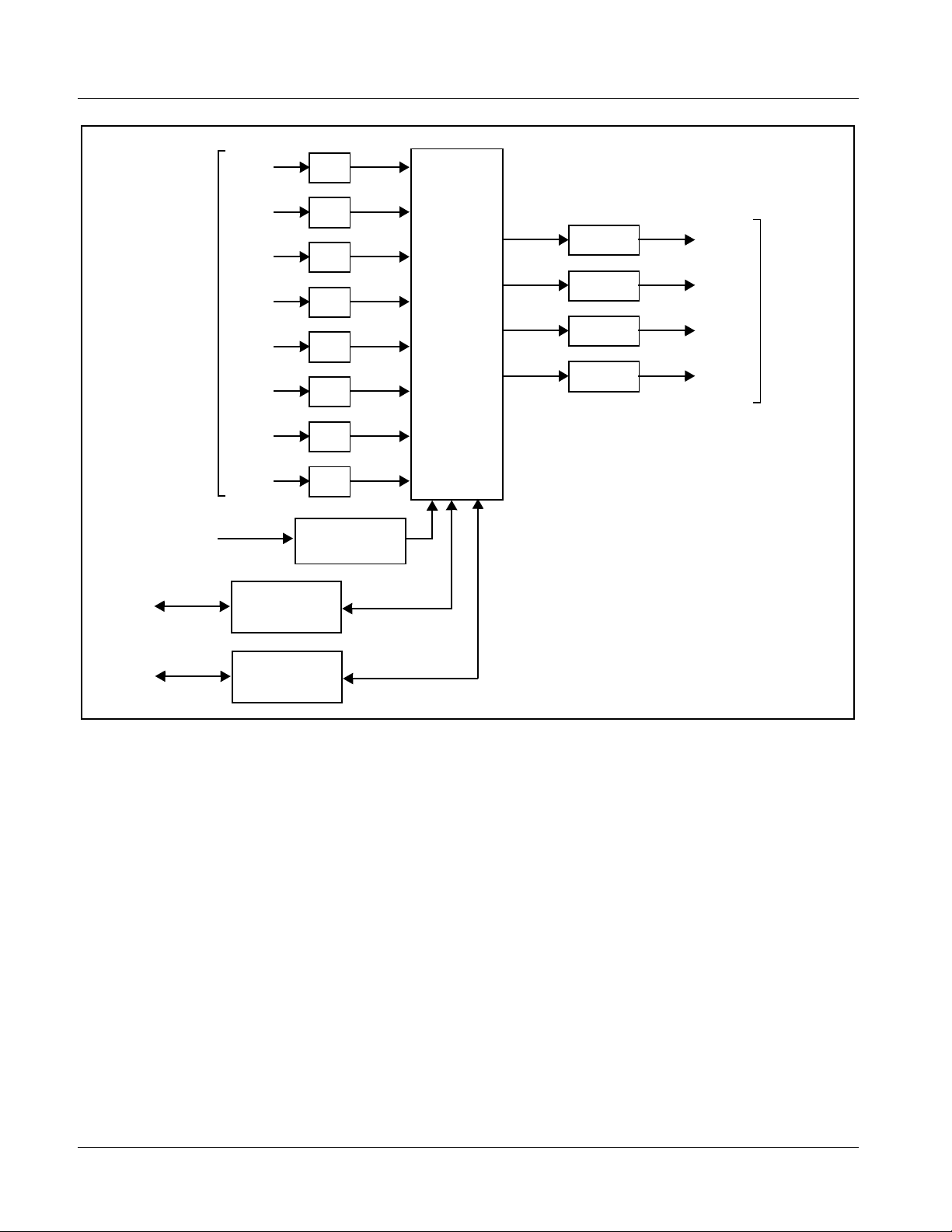
9284 Functional Description
Figure 1-1 shows a functi onal block diagram of the 9284. The 9284 video
routing switch accepts up to eight SDI inputs and routes these inputs to up to
four SDI outputs using DashBoard™ network remote control. All inputs are
equipped with cable equal izer s (which can be ena bled or disabl ed as de sired ).
All outputs are equipped with reclocking, which can independently be set for
auto reclock, format-specific reclock, or reclock turned off.
Source-to-destination routing is non-inverting, thereby allowing the card to
pass DVB-ASI signals.
The card switches on the corr ect line in the ve rtical blank ing interv al if a color
black reference is pres ent at one of the two reference i nput s on the rear of the
frame. (The reference and video formats mus t have the same frame rate or
have frame rates between the reference and video that have a ratio of either
1:2 or 2:1, i.e. 29. 97 Hz fr ame rate r efer ence with a vide o frame of 59.9 4 Hz.)
The switch point defaults to the mid line (50%) point and can be adjusted for
±2 lines or 1%-99% of the line.
Setup of routing and invoke of switching can be performed using
DashBoard™ remote control or via RS-232 commands from an external
router via Command String Protocol (see Serial Control Interface (p. 1-8) for
more information and command string definitions).
The 9284 provides the following inputs and outputs:
• Inputs:
• IN 1 thru IN 8 – eight 3G/HD/SD-SDI BNC router source inputs
• Outputs:
• (9284 only) OUT 1 thru OUT 4 – four 3G/HD/SD-SDI BNC router
destination outputs
A reference control interface allows selection of one of two external reference
signals
EXT REF 1, 2 from the frame-distributed reference bus. This interface
additionally allows s elect io n of the frame r ate and vi de o format t o ensur e that
switching occurs during the proper po int during the verti cal blanki ng interva l.
The VBI line at which switching occurs is user selectable.
Note: The reference is used by the 9284 to indicate the VBI point at which to per-
form switching (VBI portion as indicated by the reference signal). As such, the
SDI program material inputs are expected to be frame synchronized with the
reference.
9284-OM (V1.3) 9284 PRODUCT MANUAL 1-5
Page 10
1 9284 Functional Description
To/From
LAN
3G/HD/
SD-SDI
Source
Inputs
EXT REF
IN (1,2)
Src 1
Src 2
Src 3
Src 4
Src 5
Src 6
Src 7
Src 8
Reference
DashBoard™
Remote Control
Interface
EQ
EQ
EQ
EQ
EQ
EQ
EQ
EQ
Control
8x4
Video
Routing
Crosspoint
Reclock
Reclock
Reclock
Reclock
Dest 1
Dest 2
Dest 3
Dest 4
3G/HD/
SD-SDI
Destination
Outputs
To/From
RS-232
External Router
Serial Interface
9284_8x4BD2_V1.1
Figure 1-1 9284 Functional Block Diagram
1-6 9284 PRODUCT MANUAL 9284-OM (V1.3)
Page 11
Introduction 9284 Functional Description
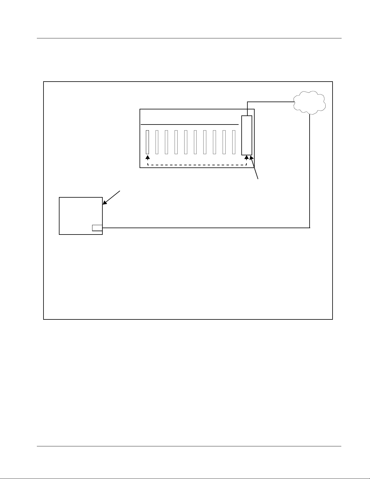
DashBoard™ User Control Interface
Figure 1-2 shows the DashBoard™ user control interface for the 9284.
LAN
20-Slot Frame with Network Controller Card
DashBoard™ Remote Control
Using a computer with
DashBoard™ installed, 9284
Computer
with NIC
Note: • To communicate with DashBoard™, the frame must have the Network Controller Card installed.
• DashBoard™ provides network control of the 9284 as shown. The value displayed at any time on
DashBoard™ is the actual value as set on the card, with the current value displayed being the
actual value as effected by the card.
card can be remotely controlled
over a LAN
Figure 1-2 9284 User Control Interface
In conjunction with a frame equipped
with a Network Controller Card, 9284
card can be remotely controlled over
a LAN
Using DashBoard™, the 9284 and other cards installed in openGear®1
compatible frames such as the Cobalt
®
HPF-9000 or 8321 frame can be
controlled from a computer and monitor.
DashBoard™ allows users to view all frames on a network with control and
monitoring for all popul ated slots insid e a frame. This simplif ies the setup and
use of numerous modules in a large installation and offers the ability to
centralize monitoring. Cards define their controllable parameters to
DashBoard™, so the control interface is always up t o date.
1. openGear® is a registered trademark of Ross Video Limited. DashBoard™ is a trademark of Ross
Video Limit e d .
9284-OM (V1.3) 9284 PRODUCT MANUAL 1-7
Page 12

1 9284 Functional Description
The DashBoard™ software can be downloaded from the Cobalt Digital Inc.
website: www.cobaltdigital.com
The DashBoard™ user interface is described in Chapter 3,“Operating
Instructions”.
(enter “DashBoard” in the search window).
Serial Control Interface
Note: If network remote control is to be used for the frame and the frame has not yet
been set up for remote control, Cobalt
User Guide (PN 9000RCS-RM) provides thorough information and
step-by-step instructions for setting up network remote control of COMPASS
cards using DashBoard™.
Download a copy of this guide by clicking on the Support>Reference Docu-
ments link at www.cobaltdigital.com and then select DashBoard Remote
Control Setup Guide as a download, or contact Cobalt
Cobalt Digital Inc. (p. 1-26).
®
reference guide Remote Control
®
as listed in Contact
The 9284 rear module is equipped with an RS-232 serial control connector
which provides a generic Command String Protocol interface between this
card and external control systems. The RS-232 serial control port supports
baud rates of 9600, 38400, and 115200.
RS-232 pinout is as follows:
• Pin 2……….TX
• Pin 3……….RX
• Pin 5……….GND
®
Generic Protocol
Commands are sent to a r out ing switcher in a group called a command stri ng.
A command string can contain zero or more commands, limited only by the
size of the receive buffer of the router, whose size depends on the particular
router model. A command string consists of a leader string of asterisk
characters, zero or more command s, and a tr ailer s tring of exclamation mar ks.
Larger Routing Switchers require two leader (
while small Routing S witchers req uire o nly one, in order to make the pr otocol
compact for those Routing Switchers. The remainder of this document gives
examples using doubled characters. Note that two leader/trailer characters
may be sent to small Rout ing Switchers even when only one is required, and
they will still work fine.
If a leader character (
**) is encountered within a command string being
processed by a router, the string up to that point is discarded and a new
command string is expected. This ensures that a router will always act on a
complete command st ring sent to it, even if the previous one was never
completely received.
**) and trailer (!!) characters,
1-8 9284 PRODUCT MANUAL 9284-OM (V1.3)
Page 13

Introduction 9284 Functional Description
When a command string is received, i t is not ac ted upon ( but rat her, is merely
buffered up) until the final trailer character (
string is received. At that time, the routing switcher begins to execute the
commands within the string.
The protocol uses only 7-bit ASCII characters. The 8th bit of received
characters is treated as if it is 0. Within the command string, certain ASCII
characters may be present and are ignored: any ASCII character whose code
is less than the SPACE character (includes all control characters and the
SPACE charact er) and the DEL (ASCII 7F) character. Alphabetic characters
within the command string may be in either upper-case or lower-case letters.
The router always sends upper case characters, except for character strings
such as input, output, and level names, whic h may ha ve lower cas e c haracter s
in them.
When sending commands to the router, SPACE characters are optional, but if
used may only appear before and after each individual command and not
embedded within an indivi dual comman d. Within command strings sent from
the router, a single SPACE character appears before and after each indiv idu al
command. SPACES may also appear in character strings.
!) character of the comma nd
After the command string has been executed, the routing swit cher returns the
string “
OK “ (with a single space character before and after the word “OK”),
followed by a string of trailer characters (exclamation marks) and a CR
(carriage return, ASCII 0D) character, to the host. This indicates that the
command has executed successfully. If an error occurs within any command
of a command string, the remai nde r of th e command string is ignor ed a nd t he
router returns the stri ng “
ERROR “, followed by an optional descripti ve string
followed by a string of trailer characters and a CR characte r, to the host. An
error can be caused by an unknown command name or bad arguments to a
command.
The simplest possible command string would be:
**!!
which consists of the leader and trailer characters but no commands between
them. This command string would generate the response:
** OK !!<CR>
This can be useful f or ver ifyi ng that the se rial link t o the r outer is ope rati onal.
In Routing Switchers requiring only one leader/trailer character, the simplest
command string would be:
*!
which would generate the response:
* OK !<CR>
9284-OM (V1.3) 9284 PRODUCT MANUAL 1-9
Page 14

1 9284 Functional Description
(To determine whether a particular router uses one or two leader/trailer
characters, send it “
responses it is. It won't hurt to always use two even if only one is required.)
The simplest error response is one with no optional descriptive string. For
example, this command string:
** XXX !!
might generate this res ponse from th e router:
** ERROR !!
Beginning with version 5.01 of the Tahoe/Sierra/Yosemite router software, a
descriptive text string was added following the word “ERROR”, to help with
diagnosing the error. For example, the above command string might generate
this response from a router running this newer software:
** ERROR Syntax:No Number:XX !!
The descriptive string always ends with a colon and up to three characters
from the command string that caused the error. Generally, the error can be
assumed to have occurred just before these characters.
!!**” and check t he res ponse t o see whi ch of the ab ove two
The following commands are supported:
Syntax Example Response
Command
I **I!! I Command capabilities
Q **Q!! Q Model name and version
L **L!! L Matrix size and level names
S **S!! V, Y, or X
commands
O out **O3 V, Y, or X
commands
N in **N2!! V, Y, or X
commands
CLEAR **CLEAR!! V, Y, or X
commands
V out, in,in... **V3,1,2,2!! V, Y, or X
commands
X out,in,lvl **X12,9,2!! V, Y, or X
commands
Matrix status
Output status
Input status
Set all outputs to input 1
Connect specified inp uts on each
level
Connect specified input to output on
level
Function
Y out,in **Y1,7!! V, Y, or X
commands
T reg **TB!! V, Y, or X
commands
Connect specified input to output on
all levels
Trigger a salvo connect sequence
1-10 9284 PRODUCT MANUAL 9284-OM (V1.3)
Page 15

Introduction 9284 Functional Description
“I”: Capabilities Inquiry
From Syntax Description
Host I Ask router to send a li st of
Router ![B][C][D][F][G][H][K][L][M][N][O][P][Q][R][S][T][U][V][W][X][W][Z]– Available commands (contents in
commands that are available
brackets is option al dep ending on
router)
The command “I” requests that command ca pability information be returned
to the host. The inform ation is sent as a string of character s. The first
characters are a space followed by “
I”, the next character s are the letter s of the
commands that are implemented and available in this router, and the last
character i s “
~” (tilde). Do not count on the characters being in any specific
order. Search all characters for a particular one.
All routing switchers implement the
I, L, S, Q, and X commands.
For example, the command:
**I!!
might return the follow ing string:
** ILSX~ OK !!<CR>
indicating that the router supports the I, L, S, and X commands from the host.
“Q”: Model Name and Software Version Inquiry
From Syntax Description
Host Q Ask router to send the model name
Router Qmodel~version~ Router Model name string and
The command “Q” requests that the router model name and software version
number string be returned to the host. The information is sent as a string of
characters. The first characters are a space followed by “
characters are the router model name, terminated by a “
Following this are the characters of the software version number string, again
terminated by a “
~” (tilde).
For example, the command:
**Q!!
string and software version number
string.
software version number string.
Q”, the next
~” (tilde).
9284-OM (V1.3) 9284 PRODUCT MANUAL 1-11
Page 16

1 9284 Functional Description
might retur n the following string:
** QSmall~V2.1~ OK !!<CR>
indicating that the router model name is “Small” and the software version
number is “V2.1”.
“L”: Matrix Size and Level Names Inquiry
From Syntax Description
Host L Ask router to send router matrix size,
Router L[O[(#,#...)]][S[(#,#...)]][P[(#[=#][M][L],...)]]Nout,Nlvl,Nin,lvl1~lvl2~...
lvlN~~
level names, and level information.
Matrix size, level names, and level
information.
The command “L” requests that matrix size (Nout, Nlvl, Nin) and level name
information (lvl1 , lvl2, e tc.) be ret urned to t he host . The informat ion is sen t as
a string of characters. The first characters are a space followed by “
L”, some
optional values described below, then the number of outputs (Nout), a
comma, the number of levels (Nlvl), a comma, the number of inputs (Nin), a
comma, and then the level names, each terminated by a “
~” (tilde), and the
last followed by two tildes.
Routers can provide names for inputs, outputs, and levels. The number of
characters in a name can vary depending on the router model. The “
L”
command provides access only to level names, and furthermore, it truncates
any level name that is l onger than 6 chara cters to onl y 6 charact ers, in or der to
retain compatibility with older routers and controlling devices that limited
level names OG-RTR 15 to 6 characters. Refer to the “
G” command fo r
accessing input and output names and full-length untruncated level names.
The number of level names in the “
L” command will be the same as the
number of levels that was given in the response (Nlvl). Valid characters for
level names are any printable (i.e. non-control) ASCII character (including
SPACE) except “
number of characters report ed by the “
more than 6 (longer names are truncated when re porting them with “
*” (asterisk), “~” (tilde), and “!” (exclamation mark). The
L” command in level names may be no
L”). In
systems that do not support naming of levels, the level names will be fixed
number strings, e.g. “1”, “2”, etc.
For example, the command:
**L!!
might retur n the following string:
** L64,3,32,VIDEO~AudioL~AudioR~~ OK !!<CR>
indicating that t he route r has 64 outputs, 3 levels , and 32 inputs, a nd the l evels
are named “VIDEO”, “AudioL”, and “AudioR”.
1-12 9284 PRODUCT MANUAL 9284-OM (V1.3)
Page 17

Introduction 9284 Functional Description
Some routers can have different sized matri ces on each level. However, the
“L” command always reports what is referred to as the “basic router size”.
This is the size of the lar gest le vels in the rout er. For example, a 2-level router
with level 1 being 16x32 and level 2 being 32x16 would report a basic router
size of 32x32 in the “L” command. In these kinds of routers, it is not
considered an error to send a crosspoint command that specifies an all-levels
take using an input or output number that is beyond the range of some of the
levels, as long those numbers l ie within the basic rout er siz e. Levels which a re
smaller than the specified numbers will not be affected by such a take
command. On the other hand, it is an err or to se nd a cros spoint command tha t
specifies a take on a specific level with an input or output number that is
beyond the range of that level. To find out the actual physical size of each
level, use the “G LEVEL_INFO” command.
Routers that do not support the “
G” command or “G LEVEL_INFO”
subcommand always have the same-size crosspoint matrix on each level.
Some routers support virtual-to-physical mapping. These virtual-mapped
routers use the same vi rtual matrix size for each level, and it will be that size
that is reported in the “
crosspoint matrices can still be different sizes, and the “
L” command for Nout and Nin. The physical
G LEVEL_INFO”
command can be used to find out what these sizes are, but they are of less
importance in a virtual-mapped router, because take commands are specified
using virtual source and destination numbers rather than physical input and
output numbers.
“S”: Status Inquiry
From Syntax Description
Host S Ask router to send source status of
Router Y out,in or V out,in,in... or X out,in,lvl Status of all outputs connected on
The command “S” requests that matrix status information be returned to the
host. The status information is sent as a sequence of “Y” and/or “V” and/or
“X” commands. The order of the commands is not significant, and different
models of routers may send the status of their outputs 16 in different orders.
Each command string contains the output number and either a level number
or data for all levels, so the order in which the status data is sent is not really
important.
all router outputs.
one or more levels to the specified
input.
For example, the SVS Tahoe Series routers first send one or more commands
that give the status for all levels of output 1, then send commands giving
status for all levels of output 2, etc. Other routers may send commands in a
different order: first for all outputs of level 1, then for all outputs of level 2,
etc.
9284-OM (V1.3) 9284 PRODUCT MANUAL 1-13
Page 18

1 9284 Functional Description
The “Y”, “V”, and “X” commands are formatted exactly as with the “O”
command.
Refer to th e “O” command description for informat io n abo ut whet her the
router sends status using only “X” commands, or “Y”, “V”, and “X”
commands.
A 2-level 16-output router could generate as many as 2 x 16 = 32 “X”
commands of status output. For example, the command:
**S!!
might have the following four “X” commands at the beginning of its
Response:
** X1,23,1 X1,3,2 X2,-,1 X2,0,2
This indicates that output 1 is connected to input 23 on level 1, output 1 is
connected to input 3 on level 2, output 2 is unconnected on level 1 (as
indicated by the dash fo r the in put number ), and outp ut 2 eit her d oes not ex ist
or is not availa ble on level 2 or its c onne ction is un known (as indi cated by the
zero input number). Or, the router might instead use the V command. For
example:
** V1,23,3 V2,-,0
Indicating the same as the previous example.
If the router has only one level, or if all levels are connected the same, it
might instead use the Y command. For example:
** Y1,23 Y2,-
This indicates that output 1 is connected to input 23 and output 2 is
unconnected.
Routers that are unmapped port units will produce symmetrical status output,
(i.e. if there is a Y01,23 command, there will also be a Y23,01 command).
“O”: Output Status Inquiry
From Syntax Description
Host O Out Ask router to send source status for
Router Y out,in or V out,in,in... or X out,in,lvl Source status of the specified output.
all levels of specified output.
The command “O” requests that m atrix status informatio n for a single o utput
be returned to the host. The status information is sent as a “Y” command or a
“V” command or as a sequence of L “X” commands, where L=number of
levels. Whether a “Y”, “V”, or “X” command is sent depends on several
factors:
1-14 9284 PRODUCT MANUAL 9284-OM (V1.3)
Page 19

Introduction 9284 Functional Description
• Very old routers only supported the “X” command.
• Routers with pre-version-10 software supported all three commands, “Y”,
“V”, and “X”, but usually provided a DIP swi tch tha t coul d be set t o forc e the
router to only send “X” commands.
• Routers with version 10 or later software use the setting of the “U”
command (described below) to determine whether to send only “X”
commands, or “Y”, “V”, and “X” commands.
A 6-level router using only “X” commands could generate as many as 6 “X”
commands of status output. The first command is for level 1, the next for
level 2, etc. until the last level is reached. (However, each “X” command
contains the level num ber, so the sequence in which the data is se nt is not
really important.)
When a router is able to send “Y”, “V”, and “X” commands, a “Y” command
will typically be sent if the router has only one level, and may also be sent if
the output has all of its levels connected the same, although this is not
required and some routers may instead send a “V” command or a series of
“X” commands in that situation. A “V” command will be sent when an output
has different connections on different levels, which is a more compact
representation of the status than a series of “X” commands.
The length of a “Y” or “V” or “X” command depends on the size of the
particular router involved. Larger routers use longer numbers for inputs,
outputs, a nd levels.
A space character pr ec ede s each “Y” or “V” or “X” command (spaces should
be ignored by the command parse r, however). Each command begins wi th t he
command letter, a Y or V or X, followed by the output number and a comma
character. Followin g that, the “Y” command has the input number connected
to the outp ut, the “V” command has L input numbers separated by commas
(
L=number of levels) in orde r by l evel numbe r, and the “X” command has the
level number at which the input-output pair is connected.
The input number may be a dash ('-') if no connection exists (for routers that
are capable of having their inputs disconnected). The input number may be 0
if the output doesn't exist at that level in the router (or isn't mapped to a
physical output, in virtual-mapped routers), or if the connection is not known
by the controller, as may be the case for some control panels immediately
after they are powered up.
For example, the command:
**O5!!
to a 3-level router might have the following three commands as its Response:
** X65,23,1 X5,-,2 X5,0,3 !!
9284-OM (V1.3) 9284 PRODUCT MANUAL 1-15
Page 20

1 9284 Functional Description
Note the dash, indicating that on level 2, output 65 is not connected to an
input. Also note the 0, indicating that the connection on level 3 is either
unknown or that output 65 doesn't exist or isn't mapped on level 3.
Or, a 3-level router might have the following single command as its
Response:
** V65,23,-,0 !!
which has th e same information as the three X commands in the p revious
example.
If the router has only one level, or if all levels are connected the same, the
router might instead use the Y command. For example:
** Y65,23 !!
The number of digits used for each number depends on the router. Newer
routers use the minimum number of digits n ecessary, i.e. there are no
unnecessary leading zeroes in a number. Older routers use the maximum
number of digits ever requir ed for an input or out put number on that pa rticular
router (e.g. a router with between 10 and 99 inputs would use two digits for
the input number).
“N”: Input Status Inquiry
From Syntax Description
Host N In Ask router to send status of outputs
Router Y out,in or X out,in,lvl Status of all outputs connected on
The command “N” requests that matrix status information for a single input
be returned to the host. The stat us infor mation is sent as one or more “Y” and/
or “X” commands. This command works by identifying all outputs that
connect to the specified input on any level, and then generating “Y” and “X”
status commands to report the status of those outputs. The “Y” and “X”
commands are formatted exactly as with the “O” command. For any given
output connected to the input, a “Y” command is used if the output is
connected to the input on all levels, else “X” commands are used on all levels
on which the input is connected to that output.
connected on one or more levels to
the specified input.
one or more levels to the specified
input.
1-16 9284 PRODUCT MANUAL 9284-OM (V1.3)
Page 21

Introduction 9284 Functional Description
Prior to version 10 software, this command was only useful on those router
levels that allow an input to be connected to at most one output, and status
commands were only sent for such levels. Beginning with version 10
software, a response is generated for all outputs connected to the specified
input on any level, regardless of how many outputs that might be, and
regardless of whether the level allows only one output connection or many
output connections.
For example, the command:
**N4!!
to a router might have the following commands as its Response:
** X12,4,1 X12,4,2 X12,4,3 X13,4,4 Y23,4 !!
showing that input 4 connects to outputs (12,12,12,13) on levels 1-4, and to
output 23 on levels 1- 4.
Note that a “V” command is never us ed in th e respons e, unlike an “O” request
described above. This is because the “V” command specifies inputs
connected to an output, not outputs connected to an input.
“CLEAR”: Clear Matrix
From Syntax Description
Host CLEAR Ask router to clear all router outputs.
Router (None) All outputs are unlocked, input
The command “CLEAR” requests th at the swi tch m atrix be cl eared so tha t all
outputs are discon nected fr om inputs (in route rs where th is is p ossible) or else
all outputs at all levels have input #1 as their source (when disconnecting is
not possible). If output locks are supported, all output locks are removed by
this command. If i nput s ecuri ty is sup ported , al l inp ut secure s are remov ed by
this command. This command can take several second s to execute (dep ending
on the size of the switch matrix), and therefore the OK response at the end of
the comman d string could be quite late. In order to help ens ure that this
command isn't accidentally executed, it requires four additional characters
following the “C” character, to spell out the word “CLEAR” in full.
For example, the command:
secures are unsecured, and all
outputs are either disconnected or
connected to input 1.
**CLEAR!!
would clear the matrix, and when finished, the following response would be
generated:
** OK !!<CR>
9284-OM (V1.3) 9284 PRODUCT MANUAL 1-17
Page 22

1 9284 Functional Description
“V”: Connect Levels
From Syntax Description
Host V out,in,in... Make a connection to an output on
Router (None or V/Y/X command, depending on which “U” command
argument is in effect, see “U” command desc rip tion .)
each level.
Optional status response.
The command “V” is used to request that a connection be made. It must be
followed by an output number, a comma, and a comma-separated list of input
numbers, one for each level, up to the number of levels in the router. Fewer
than the number of levels may be specified if desired, and the remaining
levels will be left unchanged.
For example, the command:
**V12,7,8,9!!
says that connections are to be made to output 12: from input 7 on level 1,
input 8 on level 2, and input 9 on level 3.
An input number of 0 means the output connection is to be left unchanged.
An input number of '-' (dash) means the output is to be disconnected. If the
router does not support disconnected outputs, the output connection will be
left unchanged. Unless otherwise noted in the documentation for a specific
switcher, it can be assumed that the switcher software guarantees to send all
level changes associated with the “V” command's output to the crosspoint
matrix within the SAME vertical interval.
If the requested co nnection ha s an outp ut number tha t does not ex ist on one or
more levels, those levels are simply not changed. It is an error to request
connection of an input that doesn't exist on that level, even if the input does
exist on some other level. If the requested connection has an output or input
number that isn't mapped to a physical connector (on virtual-mapped routers )
on one or more levels, those levels are simply not changed.
If “U2” is in e ffe ct (se e “U” command), the resp onse will incl ude one or mor e
V, Y, or X commands to report th e ne w status of the o utput. Th e respo nse will
be the same as if an “O” command were issued for the output immediately
following the “V” command. No response is generated if this command is
being used to define a salvo.
1-18 9284 PRODUCT MANUAL 9284-OM (V1.3)
Page 23

Introduction 9284 Functional Description
“X”: Connect Crosspoint
From Syntax Description
Host X out,in,lvl Make a connection to an output on a
Router (None or V/Y/X command, depending on which "U" command
argument is in effect, see “U” command description.)
level.
Optional status response.
The command “X” is used to request that a connection be made. It must be
followed by an output number, a comma, an input number, a comma, and a
level number.
For example, the command:
**X24,13,2!!
says that a connection is to be made between output 24 and input 13 on level
2. If the level number is specified as “0”, this means that the connection is to
be made on all levels (AFV).
For example, the command:
**X8,3,0!!
says that a connection is to be made between output 8 and input 3 on all
levels.
An input number of 0 means the output connection is to be left unchanged,
not very useful in an “X” comman d.
An input number of '-' (dash) means the output is to be disconnected. If the
router does not support disconnected outputs, the output connection will be
left unchanged. When a level number of 0 is used with the “X” command, it
can be assumed that the switcher software guarantees to send all level
changes for the output to the crosspoint matrix within the same vertical
interval, unless otherwise noted in the documentation for a specific switcher.
It is an error to request connection of an input or output that doesn't exist on
the specifi ed level, eve n if it does exist on some o ther level. H owever, if the
level number is “0”, any input or output number may be speci fied as lo ng as it
exists on at le ast one level, and in t hat case no connec tion will be made on any
level on which the input or output does not exist. If the requested connection
has an output or input number that isn't mapped to a physical connector (on
virtual-mapped routers) on one or more levels, those levels are simply not
changed.
9284-OM (V1.3) 9284 PRODUCT MANUAL 1-19
Page 24

1 9284 Functional Description
If “U2” is in e ffe ct (se e “U” command), the resp onse will incl ude one or mor e
V, Y, or X commands to report th e ne w status of the o utput. Th e respo nse will
be the same as if an “O” command were issued for the output immediately
following the “X” command. No response is generated if this command is
being used to define a salvo.
“Y”: Connect AFV
From Syntax Description
Host Y out,in Make a connect ion to an outp ut on all
Router (None or V/Y/X command, depending on which “U” command
argument is in effect, see “U” command desc rip tion .)
levels.
Optional status response.
The command “Y” is used to request that a connection be made. It must be
followed by an output number, a comma, and an input number. The
connection is made on all levels (AFV).
For example, the command:
**Y2,29!!
says that input 29 is to be connected to output 2 on all levels.
An input number of 0 means the output connection is to be left unchanged,
not very useful in a “Y” command.
An input number of '-' (dash) means the output is to be disconnected. If the
router does not support disconnected outputs, the output connection will be
left unchanged.
Unless otherwise noted in the documentation for a specific switcher, it can be
assumed that the switcher softwar e guarantees to send all level changes for
the “Y” command's output t o t he crosspoint matrix within the SAME vertical
interval.
Any input or output number may be specified as long as it exists on at least
one level. No connection will be made on any level on which the input or
output does not exist. If the requested connection has an output or input
number that isn't mapped to a physical connector (on virtual mapped routers)
on one or more levels, those levels are simply not changed.
If “U2” is in e ffe ct (se e “U” command), the resp onse will incl ude one or mor e
V, Y, or X commands to report th e ne w status of the o utput. Th e respo nse will
be the same as if an “O” command were issued for the output immediately
following the “Y” command. No response is generated if this command is
being used to define a salvo.
1-20 9284 PRODUCT MANUAL 9284-OM (V1.3)
Page 25

Introduction 9284 Functional Description
“T”: Tr igger a Salvo Connect Sequence
From Syntax Description
Host T reg Trigger a list of connect commands
Router (None)
stored in a salvo register.
The command “T” is used to trigger a previously set up salvo (set using the
“P” command above). It must be fo llowed by a reg ister l ette r fr om A to Z or a
register number from 1 to 256 giving the register to be triggered.
For example, the command:
** TB D180 TC !!
says to trigger salvo register B (same as 2), delay 180 sync intervals, then
trigger salvo register C (same as 3). When the register is triggered, this means
that the connect commands stored in it take effect.
If a salvo is triggered and it attempts to connect a locked output or port, or a
disallowed input/output pair, or a port to itself , the salvo trigger operation is
aborted, no crosspoint changes are performed, and an error is reported:
“ERROR Salvo Has Locked Xpts”.
9284-OM (V1.3) 9284 PRODUCT MANUAL 1-21
Page 26

1 Technical Specifications
9284 Rear I/O Modules
The 9284 physically interfaces to system video connections at the rear of its
frame using a Rear I/O Module.
All signal inputs and outputs shown in the 9284 Functional Block Diagram
(Figure 1-1) enter and exit the card via the card edge backplane connector.
The Rear I/O Module breaks out the card edge connections to BNC
connectors that interface with other components and systems in the signal
chain.
Video Formats Supported by the 9284
The 9284 supports all current SMPTE 292M, 259, and 424 standard SD and
HD video formats. Table 1-1 lists and provides details regarding the video
formats supported by the card.
Table 1-1 Supported Video Formats
Item Description/Specification
Input / Output Video Raster Structure: Frame Rate:
1080PsF 23.98; 24
1080p 23.98; 24; 50; 59.94
(1)
1080i
720p 23.98
(1)
486i
(1)
575i
(1) All rates displayed as frame rates; interlaced (“i”) field rates are two times the rate value shown.
25; 29.97; 30
(2)
; 24
59.94; 60
29.97
25
Technical Specifications
Table 1-2 lists the technical specifications for the 9284 3G/HD/SD-SDI 8x4
Video Routing Switch card.
(2)
; 25; 29.97; 30; 50;
1-22 9284 PRODUCT MANUAL 9284-OM (V1.3)
Page 27

Introduction Technical Specifications
Table 1-2 Technical Specifica tions
Item Characteristic
Part number, nomenclature 9284 3G/HD/SD-SDI 8x4 Video Routing Switch
Installation/usage environment Intended for installation and usage in frame meeting openGear
modular system definition.
Power consumptio n < 10 Watts maximum
Environmental:
Operating temperature:
Relative humidity (operating or storage):
Frame communication 10/100 Mbps Ethernet with Auto-MDIX.
Switch Panel communication Serial; RS-232 and/or RS-485 (reserved)
Indicators Card edge indicators as follows:
32° – 104° F (0° – 40° C)
< 95%, non-condensing
• Power indicator
• Ref lock indicator
Serial Digital Video Input Number of Inputs:
Eight 3G/HD/SD-SDI BNC Source Inputs
Data Rates Supported:
SMPTE 424 HD-SDI: 2.97 Gbps
SMPTE 292 HD-SDI: 1.485 Gbps or 1.485/1.001 Gbps
SMPTE 259M-C SD-SDI: 270 Mbps
Impedance:
75 Ω terminating
Equalization (3G, HD):
328 ft (100 m) Belden 1694A for SMPTE 292-2008, 424M-2006
Equalization (SD):
1000 ft (305 m) Belden 1694A for SMPTE 259M-2008
Return Loss:
> 15 dB at 5 MHz – 1.485 GHz
> 10 dB at 1.5 GHz – 3.0 GHz
9284-OM (V1.3) 9284 PRODUCT MANUAL 1-23
Page 28

1 Technical Specifications
Table 1-2 Technical Specifications — continued
Item Characteristic
Serial Digital Video Outputs Number of Outputs:
Four 3G/HD/SD-SDI BNC Destination Outputs
Impedance:
75 Ω
Serial Digital Video Outputs (cont.) Level:
800 mVp-p ±10%
Return Loss:
> 15 dB at 5 MHz – 1.5 GHz
> 10 dB at 1.5 GHz – 3.0 GHz
Alignment Jitter:
< 0.2 UI (max; coupled through 100 kHz high-pass filter)
Reference Video Input Number of Inputs:
Two non-terminating (looping) Frame Reference inputs
Standards Supported (HD):
720p 24; 25; 29.97; 30; 50; 59.94
1080i 25; 29.97
1080p 23.98; 24; 25; 29.97; 30; 50; 59.94
1080p/sF 23.98; 24
Standards Supported (SD):
486i 29.97 (NTSC)
575i 25 (PAL)
Signal Level:
1 Vp-p nominal
Signal Type:
Analog video sync (black burst or tri-level)
Impedance:
75 Ω
1-24 9284 PRODUCT MANUAL 9284-OM (V1.3)
Page 29

Introduction Warranty and Service Information
Warranty and Service Information
Cobalt Digital Inc. Limited Warranty
This product is warranted to be free from defects in material and workmanship for a period of five (5)
years from the date of shipment to the original purchaser, except that 4000, 5000, 6000, 8000 series
power supplies, and Dolby
material and workmanship for a period of one (1) year.
Cobalt Digital Inc.'s (“Cobalt”) sole obligation under this warranty sh all be limited to, at its option, (i)
the repair or (ii) replacement of the produc t, and the det ermination of whether a defect is covered under
this limited warranty shall be made at the sole discretion of Cobalt.
This limited warrant y appl ies on ly t o the origi nal end-pu rchaser of the produ ct, and i s not assign able o r
transferrable therefrom. This warr ant y i s li mited to defects in material and workmanship, and shall not
apply to acts of God, accidents, or negligence on behalf of the purchaser, and shall be voided upon the
misuse, abuse, alteration, or modification of the product. Only Cobalt authorized factory
representatives are authorized to make repairs to the product, and any unauthorized attempt to repair
this product shall immediately void the warranty. Please contact Cobalt Technical Support for more
information.
®
modules (where applicable) are warranted to be free from defects in
To facilitate the resolut ion of warranty related issues, Cobalt recommends registering the product by
completing and returning a product registration form. In the event of a warrantable defect, the
purchaser shall notify Cobalt with a descripti on of the problem, and Cobalt shall provide the purchaser
with a Re turn Mate rial Auth oriz ation (“RMA”). For retu rn, defective product s should be double boxed,
and sufficiently protecte d, in the original packa ging, or equivalent, a nd shipped to the Coba lt Factory
Service Center, postage prepaid and insured for the purchase price. The purchaser should include the
RMA number, description of the problem encountered, date purchased, name of dealer purchased
from, and serial number with the shipment.
Cobalt Digital Inc. Factory Service Center
2406 E. University Avenue Office: (217) 344-1243
Urbana, IL 61802 USA Fax: (217) 344-1245
www.cobaltdigital.com Email: info@cobaltdigital.com
THIS LIMITED WARRANTY IS EXPRESSLY IN LIEU OF ALL OTHER WARRANTIES
EXPRESSED OR IMPLIED, INCLUDING THE WARRANTIES OF MERCHANTABIL ITY AND
FITNESS FOR A PARTICULAR PURPOSE AND OF ALL OTHER OBLIGATIONS OR
LIABILITIES ON COBALT'S PART. ANY SOFTWARE PROVIDED WITH, OR FOR USE WITH,
THE PRODUCT IS PROVIDED “AS IS.” THE BUYER OF THE PRODUCT ACKNOWLEDGES
THAT NO OTHER REPRESENTATIONS WERE MADE OR RELIED UPON WITH RESPECT TO
THE QUALITY AND FUNCTION OF THE GOODS HEREIN SOLD. COBALT PRODUCTS ARE
NOT AUTHORIZED FOR USE IN LIFE SUPPORT APPLICATIONS.
COBALT'S LIABILITY, WHETHER IN CONTRACT, TORT, WARRANTY, OR OTHERWISE, IS
LIMITED TO THE REPAIR OR REPLACEMENT, AT ITS OPTION, OF ANY DEFECTIVE
PRODUCT, AND SHALL IN NO EVENT INCLUDE SPECIAL, INDIRECT, INCIDENTAL, OR
CONSEQUENTIAL DAMAGES (INCLUDING LOST PROFITS), EVEN IF IT HAS BEEN
ADVISED OF THE POSSIBILITY OF SUCH DAMAGES.
9284-OM (V1.3) 9284 PRODUCT MANUAL 1-25
Page 30

1 Contact Cobalt Digital Inc.
Contact Cobalt Digital Inc.
Feel free to contact our thorough and professional support representative s for
any of the following:
• Name and address of your local dealer
• Product information and pricing
• Technical support
• Upcoming trade show in formation
Phone: (217) 344-1243
Fax: (217) 344-1245
Web: www.cobaltdigital.com
General Information: info@cobaltdigital.com
Technical Support: support@cobaltdigital.com
1-26 9284 PRODUCT MANUAL 9284-OM (V1.3)
Page 31

Chapter 2 Installation and Setup
Overview
This chapter contains the following information:
• Installing the 9284 Into a Frame Slot (p. 2-1)
• Installing a Rear I/O Module (p. 2-3)
• Setting Up 9284 Network Remote Control (p. 2-4)
Installing the 9284 Into a Frame Slot
Chapter 2
CAUTION
This device contains semiconductor devices which are
susceptible to serious damage from Electrostatic
Discharge (ESD). ESD damage may not be immediately
apparent and can affect the long-term reliability of the
device.
Avoid handling circuit boards in high static environments
such as carpeted areas, and when wearing synthetic fiber
clothing. Always use proper ESD handling precautions
and equipment when working on circuit boards and
related equipment.
CAUTION
If required, make certain Rear I/O Module(s) is installed before installing the
9284 into the frame slot. Damage to card and/or Rear I/O Module can occur if
module installation is attempted with car d already installed in slot.
Note: Check the packaging in which the 9284 was shipped for any extra items such
as a Rear I/O Module connection label. In some cases, this label is shipped
with the card and to be installed on the Rear I/O connector bank corresponding to the slot location of the card.
Install the 9284 into a frame slot as follows:
9284-OM (V1.3) 9284 PRODUCT MANUAL 2-1
Page 32

2 Installing the 9284 Into a Frame Slot
1. Determine the slot in which the card is to be installed.
2. Open the frame front access panel.
3. While holding the card by the card edges, align the card such that the
plastic ejector tab is on the bottom.
4. Align the card with the top and bottom guides of the slot in which the
card is being installed.
5. Gradually slide the card into the slot. When re sistance is noticed, gently
continue pushing the card until its rear printed circuit edge terminals
engage fully into the rear I/O module mating connector.
CAUTION
If card resists fully engaging in rear I/O module mating connector, check for
alignment and proper insertion in slot tracks. Damage to card and/or rear I/O
module may occur if improper card insertion is attempted.
Verify that the card is fully engaged in rear I/O module mating connector.
6.
7. Close the frame front access panel.
8. Connect the input and output cables as shown in Figure 2-1.
9. Repeat steps 1 through 8 for other 9284 cards.
Note: External frame sync reference signals are received by the card over a refer-
ence bus on the card frame, and not on any card rear I/O module connectors.
The frame has BNC connectors labeled REF 1 and REF 2 which receive the
reference signal from an external source such as a house distribution.
Note: The 9284 BNC inputs are internally 75-ohm terminated. It is not necessary to
terminate unused BNC inputs or outputs.
Note: To remove a card, press down on the ejector tab to unseat the card from the
rear I/O module mating connector. Evenly draw the card from its slot.
10. If network rem ote control is to be used for the fram e and the frame has
not yet been set up for remote control, perform setup in accordance with
Setting Up 9284 Network Remote Control (p. 2-4).
Note: If installing a card in a frame already equipped for, and connected to
DashBoard™, no network setup is required for the card. The card will be discovered by DashBo ard™ and be ready for use.
2-2 9284 PRODUCT MANUAL 9284-OM (V1.3)
Page 33

Installation and Setup Installing a Rear I/O Module
Connect cabling as shown. Unused connectors do not require external termination.
Serial RS-232 control port pinout is as follows:
Pin 2 TX
Pin 3 RX
Pin 5 GND
PANEL RS-485 port is reserved.
Figure 2-1 9284 Rear I/O Module Connections
Installing a Rear I/O Module
Note: This procedure is applicable only if a Rear I/O Module is not currently
installed in the slot where the 9284 is to be installed.
Install a Rear I/O Module as follows:
1. On the frame, determine the slot in which the 9284 is to be installed.
2. In the mounting area corresponding to the slot location, install
Rear I/O Module as shown in Figure 2-2.
9284-OM (V1.3) 9284 PRODUCT MANUAL 2-3
Page 34

2 Setting Up 9284 Network Remote Control
Align and engage mounting tab on Rear
I/O Module with the module seating slot
1
on rear of frame chassis.
DSCN3483A.JPG
Hold top of Rear I/O Module flush against
frame chassis and start the captive screw.
2
Lightly tighten captive screw.
DSCN3487A.JPG
Figure 2-2 Rear I/O Module Installation
Setting Up 9284 Network Remote Control
Perform remote control setup in accordance with Cobalt® reference guide
“Remote Control User Guide” (PN 9000RCS-RM).
Note: • If network remote control is to be used for the frame and the frame has not
yet been set up for remote control, Cobalt
Control User Guide (PN 9000RCS-RM) provides thorough information and
step-by-step instructions for setting up network remote control of
COMPASS™ cards using DashBoard™.
Download a copy of this guide by clicking on the
Support>Reference Documents link at www.cobaltdigital.com and then
select DashBoard Remote Control Setup Guide as a download, or contact
®
Cobalt
• If installing a card in a frame already equipped for, and connected to
DashBoard™, no network setup is required for the card. The card will be discovered by DashBoard™ and be ready for use.
as listed in Contact Cobalt Digital Inc. (p. 1-26).
®
reference guide Remote
2-4 9284 PRODUCT MANUAL 9284-OM (V1.3)
Page 35

Overview
Chapter 3
Chapter 3 Operating Instructions
This chapter contains the following information:
If you are already familiar
with using DashBoard or a
Cobalt Remote Control
Panel to control Cobalt
cards, please skip to 9284
Function Submenu Li st and
Descriptions (p. 3-9).
• Control and Display Descriptions (p. 3-1)
• Accessing the 9284 Card via DashBoard™ (p. 3-5)
• Checking 9284 Card Information (p. 3-7)
• Operating Controls Overview (p. 3-8)
• 9284 Function Submenu List and Descriptions (p. 3-9)
• Troubleshooting (p. 3-17)
Control and Display Descriptions
This secti on describes the user interface co ntrols and indicators, and displays
(both on-card and remote controls) for using the 9284 card.
Note: When a setting is changed, settings displayed on DashBoard™ are the set-
tings as effected by the card itself and reported back to the remote control; the
value displayed at any time is the actual value as set on the card.
9284-OM (V1.3) 9284 PRODUCT MANUAL 3-1
Page 36

3 Control and Display Descriptions
Function Submenu/Parameter Submenu Overview
The functions and related parameters available on the card are organized into
function submenus, which consist of parameter groups as shown below.
Figure 3-1 shows how the card and its submenus are organized, and also
provides an overview of how navig ation is performed be tween cards, func tion
submenus, and parameters.
Using DashBoard™, the desired 9284 card is first selected.
9284
Submenu a Submenu b
Individual Parameters
Each submenu consists of groups of parameters
related to the function submenu. Using the “I/O
Settings” function submenu example, the individual
parameters for this function consist of Conf igure
Sources, Configure Destinations and related channel
settings .
Figure 3-1 Function Submenu/Parameter Submenu Overvie w
• • •
The desired function submenu is next
selected.
Function Submenus consist of parameter
groups related to a particular 9284 card
function (for example, “I/O Settings”).
Submenu z
3-2 9284 PRODUCT MANUAL 9284-OM (V1.3)
Page 37

Operating Instructions Control and Display Descriptions
9284 Card Edge Indicators
Figure 3-2 shows and describes the 9284 indicators.
Power Indicator
Reference Lock Indicator
9284
Item Function
Power
Indicator
Reference
Lock
Indicator
Illuminates when card is properly powered up and inserted into frame slot
Illuminates when card is receiving valid reference signal on selected reference source (EXT REF 1
or EXT REF 2)
DashBoard™ User Interface
Figure 3-2 9284 Card Edge Indicators
(See Figure 3-3.) The card function submenus are organized in DashBoard™
using tabs (for exampl e, “I/O Se ttin gs” in Figu re 3 -3). When a tab is selec ted,
each item associated with the function is displayed. Items can then be
configured or selected using GUI drop-down lists, checkboxes/buttons, or
text entry fields as appropriate.
In this example, car d dest inati on out puts
Dest 1 thru Dest 4 are named to su it
the intended uses (in thi s example, “Playout A” thru “Playout C” and
“Monitor”), with all outputs set to be auto reclocking. Card source inputs
Src 1 thru Src 5 are named t o identi fy plant IRD source s and vide odecks (Src
thru Src 8 are not used in this example).
6
9284-OM (V1.3) 9284 PRODUCT MANUAL 3-3
Page 38

3 Control and Display Descriptions
Access I/O Settings tab to name
and configure inputs (sources)
and outputs (destinations)
Apply desired names and
properties for destinations
in Configure Destinations
portion
Apply desired names and
properties for sources in
Configure Sources
portion
Figure 3-3 DashBoard™ Setup of Example I/O Sources and Destinations
9284_DBEX.PNG
3-4 9284 PRODUCT MANUAL 9284-OM (V1.3)
Page 39

Operating Instructions Accessing the 9284 Card via DashBoard™
Accessing the 9284 Card via DashBoard™
Access the card using DashBoard™ as described below.
1. On the computer connected to the frame LAN, open DashBoard™.
2. As shown be low (in the left side Basic View Tree) locate the Network
Controller Card asso ci ated wi th th e fra me co ntain ing th e 9284 c ard t o be
accessed (in this example, “MFC-8320-N SN: 00108053”).
DB_ACCESS1.PNG
3. As shown below, expand the tree to access the cards within the frame.
Click on the card to be accessed (in this example,
“Slot 6: CDI-9284”).
.
DB_ACCESS2A.PNG
As shown on the next page, when the card is accessed in DashBoard™
its function submenu scree n showing ta bs for eac h functi on is disp layed.
(The particular submenu screen displayed is the previously displayed
screen from the last time the card was accessed by DashBoard™).
9284-OM (V1.3) 9284 PRODUCT MANUAL 3-5
Page 40

3 Accessing the 9284 Card via DashBoard™
Card Access/Navigation
Tree Pane
Card Info
Pane
Card Function Submenu
and Controls Pane
9284_DB_ACCESS.PNG
3-6 9284 PRODUCT MANUAL 9284-OM (V1.3)
Page 41

Operating Instructions Checking 9284 Card Information
Checking 9284 Card Information
The operating status and software version the card can be checked using
DashBoard™. Figure 3-4 shows and describes the card information screen
using DashBoard™.
Note: Proper operating status in DashBoard™ is denoted by green icons for the sta-
tus indicators shown in Figure 3-4. Yellow or red icons respectively indicate
an alert or failure condition. Refer to Troubleshooting (p. 3-17) for corrective
action.
The Tree View shows the cards seen by DashBoard™.
In this example, Network Controller Card MFC-8320-N
(serial number ...8053) is hosting a 9284 card in slot 6.
Card State Product/Status Display
Product and Status tabs in Card Info pane show
Product Info (shown in example here) or detailed card
status when Status tab is selected (this tab is shown in
detail later in this chapter).
Software Version Number
Refer to these numbers to check that documentation (such as
this manual) matches the card’s Software Release Number
and Software Build Number. Use these numbers also when
communicating to Cobalt
Power Consumption Display
This display shows the total power consumed by the
card for both the +12V and -7.5V rails.
Board Status Display
Show the status of all card internal monitoring alarms.
®
regarding this card.
Figure 3-4 9284 Card Info Utility
9284_CARD_INFO.PNG
9284-OM (V1.3) 9284 PRODUCT MANUAL 3-7
Page 42

3 Operating Controls Overview
Operating Controls Overview
The card has several function submenus (“tabs”) which are used as follows,
and typically in the order listed here for initial setup.
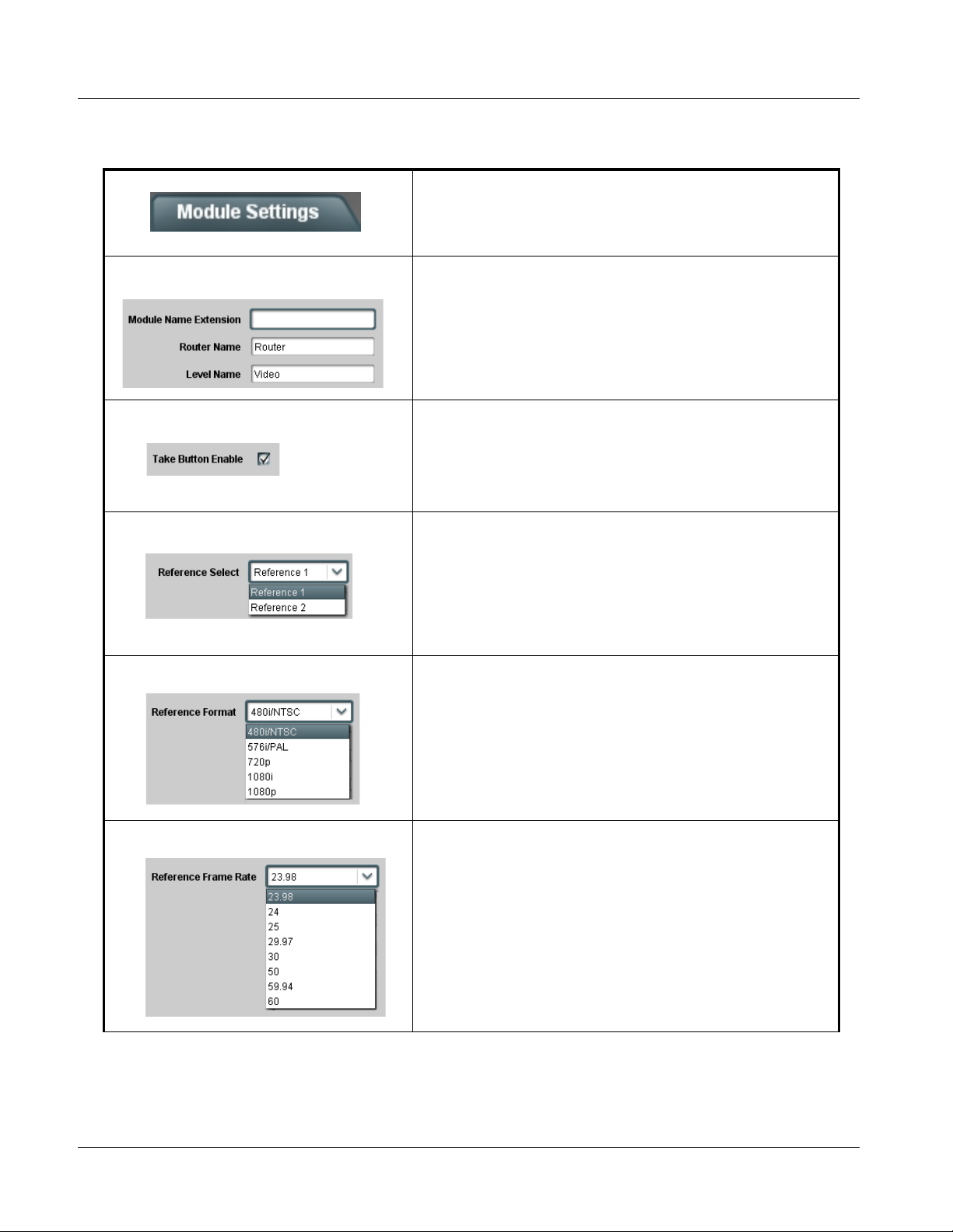
• Module Settings tab – Items in this tab set global parameters for the
card, such as the frame re fer ence source to be used, video format and
frame rate, and the VBI line where switching is to be performed.
Items in this tab should be set first before proceeding to other tabs
or attempting to use the card for switching.
• I/O Settings tab – Items in this tab allow custom names to be applied
to the card source inputs and destination outputs. Also provided are
channel properties controls that enable or disable input EQ, output
reclocking, and alarm enable/severity level for each input and output
channel.
• Salvos tab – Items in this tab allo w configuring the
source-to-destination routing for up to 10 user-defined s al vos using a
source-to-destination selection matrix. Also provided are fields in
which each salvo can be given a custom name if desired.
• Control tab – This is the tab from which a salvo is launched. When
inputs/outputs and salvo routing are defined (as described for the
above tabs), the salvos will be identified by the names you have
entered, as well as the routing defined for each salvo.
• Host Settings tab – These controls are reserved.
• Panel Settings tab – These controls are reserved.
3-8 9284 PRODUCT MANUAL 9284-OM (V1.3)
Page 43

Operating Instructions 9284 Function Submenu List and Descriptions
9284 Function Submenu List and Descriptions
Table 3-1 individually lists and des cr ibe s e ach card function submenu (“tab”)
and its related list selections, co ntrols, and parameters . Where helpful,
examples showing usage of a function are also provided.
Note: All numeric (scalar) parameters displayed on DashBoard™ can be changed
using the slider controls, arrows, or by numeric keypad entry in the corresponding numeric field. (When using numeric keypad entry, add a return after
the entry to commit the entry.)
Note: For any text entries made using the card GUI (unless accompanied by a Save
button), commit the changes using the card Refresh button.
On DashBoard™ itself and in Table 3-1, the function submenu items are
organized using tabs as shown below.
The table below provides a quick-reference to the page numbers where each
function submenu item can be found.
Function Submenu Item Page
Module Settings
I/O Settings
Salvos
Control
Note: Host Settings and Panel Settings tabs are for dedicated serial communica-
tion control and are reserved for this product’s release.
3-10
3-12
3-14
3-15
9284-OM (V1.3) 9284 PRODUCT MANUAL 3-9
Page 44
3 9284 Function Submenu List and Descriptions
Table 3-1 9284 Function Submenu List
Provides controls for setting global card parameters,
such as frame reference source, video format and
Module Settings
frame rate, and VBI switching line contr ol.
• Card Naming Entry Allows custom names to be applied to the card (which are then visible in
• Take Button Enable When checked, inserts a Take button on the Control screen which allows
• Reference Select Selects the frame distributed reference source to be used by the card.
• Reference Format Configures the card to operate with the received reference format from
DashBoard™).
Note: Module Name Extension field allows a maximum of 33
characters.
Router Name field allows a maximum of 21 characters.
Level Name field allows a maximum of 9 characters.
settings to be entered and then only applied when finished by clicking the
Action > Take button. If Take Button Enable is not checked, the card will
“take” each time a source is selected.
Note: Refer to Control tab for more information related to the Take
function.
Note: If Reference 1 or Reference 2 is selected and an
appropriate external reference is not received, improper
switching may occur, with switching possibly occurring in
active video. External reference signals Reference 1 and
Reference 2 are distributed to the card and other cards via a
frame bus.
the choices shown to the left.
Note: Reference Format selected should match that of the
external reference. If improperly set, switching may occur
during active video.
• Reference Frame Rate Configures the card to operate with the received reference frame rate
from the choices shown to the left.
Note: Reference Frame Rate selected should match that of the
external reference. If improperly set, switching may occur
during active video.
3-10 9284 PRODUCT MANUAL 9284-OM (V1.3)
Page 45

Operating Instructions 9284 Function Submenu List and Descriptions
Table 3-1 9284 Function Submenu List — continued
(continued)
• Video Format Configures the card to operate with the video format of the input sources
• Video Frame Rate Configures the card to operate with the video frame rate of the input
• Switch Line / Switch Line Fine Adjust
received from the choices shown to the left.
Note: Video Format selected should match that of the input
sources. If improperly set, switching may occur during
active video.
sources received from the choices shown to the left.
Note: Video Frame Rate selected should match that of the input
sources. If improperly set, switching may occur during
active video.
Switch Line sets VBI line where switching will occur (default is line 12 for
all format selections).
Switch Line Fine Adjust sets the horizontal point within the line where
switching will occur (0% to 100% range in 1% steps; default = 50%
(mid-line))
Recommended typical switching lines are as follows:
Format Switching Line
NTSC 10
PAL 6
3G/HD 7
Note: M ake certain selected switching line is not being used to
carry active VANC data or packets.
9284-OM (V1.3) 9284 PRODUCT MANUAL 3-11
Page 46

3 9284 Function Submenu List and Descriptions
Table 3-1 9284 Function Submenu List — continued
Allows custom names to be applied to card source
inputs and destination outputs. Also provides channel
I/O Settings
properties controls and alarm enable/severity level for
each input and output channel.
• Configure Source Setup Individual source name and setup controls for each of the card source
• Configure Destination Setup Individual destination name and setup controls for each of the card
input channels (Src 1 thru Src 8).
• Name: Allows custom name to be applied to input (in this example,
“IRD1”). The custom name then appears elsewhere on all card
controls.
Note:Name field allows a maximum of 8 characters.
• EQ Enable: When checked, provides input EQ correction to
accommodate long cable lengths (default setting is Enabled)
• Alarm Mode: Allows signal absence alarm enable/severity reporting
for each input channel. Choices provided are:
• Ignore: Missing input status for input channel is ignored, no
alarms shown for channel regardless of signal status.
• Warning: Missing input status for input channel triggers yellow
alarm icon for input channel.
• Alarm: Missing input status for input channel triggers red alarm
icon for input channel.
Note:If a source is not intended to be used, make certain its Alarm
Mode is set to Ignore. If t his is not done, the card will display
nuisance alarms for unused channels.
destination output channels (Dest 1 thru Dest 4).
• Name: Allows custom name to be applied to output (in this example,
“PlayoutA”). The custom name then appears elsewhere on all card
controls.
Note:Name field allows a maximum of 8 characters.
• Reclocker: Provides reclocking from the choices shown to the left.
• Auto: W hen Auto is selected, clocking is automatically detected
from the routed source signal with output locking to the SMPTE
format of the incoming input signal. If a non-SMPTE data rate is
detected, reclocking automatically enters a bypass mode, passing
the signal without reclocking.
• SD, HD, 3G: Provides forced reclock modes correlating to the
selection.
Note:Default setting of Auto is recommended in most cases.
• Alarm Mode: Allows signal absence alarm enable/severity reporting
for each output channel. Choices provided are:
• Ignore: Missing output status for output channel is ignored, no
alarms shown for channel regardless of signal status.
• Warning: Missing output status for output channel triggers yellow
alarm icon for output channel.
• Alarm: Missing output status for output channel triggers red alarm
icon for output channel.
Note:If a destination is not intended to be used, make certain its
Alarm Mode is set to Ignore. If this is not done, the card will
display nuisance alarms for unused destinations.
3-12 9284 PRODUCT MANUAL 9284-OM (V1.3)
Page 47

Operating Instructions 9284 Function Submenu List and Descriptions
Table 3-1 9284 Function Submenu List — continued
(continued)
I/O Settings
Source and Destination Channel Status Displays
Source and destination channel status (such as signal presence) can be observed by selecting the Status tab within the
Card Info pane. Note that Warning (yellow) and Alarm (red) status indications are only displayed when the channel is set to
display these alarms (as described on the previous page). Shown below are example status displays.
Example Destination channel display showing
locked HD signal and green (OK) status
Example Destination channel display showing
unlocked signal and red (Alarm) status
In this example, destination channel Alarm Mode
is set to Ignore. Even though the channel shows
unlocked, a alarm is not produced. This setting is
useful for channels which are not to be used.
Example Source channel display showing no
signal and yellow (Warning) status
In this example, source channel Alarm Mode is
set to Ignore. Even though the channel shows no
signal, a alarm is not produced. This setting is
useful for channels which are not to be used.
9284-OM (V1.3) 9284 PRODUCT MANUAL 3-13
Page 48

3 9284 Function Submenu List and Descriptions
Table 3-1 9284 Function Submenu List — continued
Defines the source-to-destination routing for up to 10
user-defined salvos. Also provides fields for custom
Salvos
Destination
Rows
Controls
Salvo
Edit
Dest 1
Dest 2
Dest 3
Dest 4
Src 1 Src 2 Src 3 Src 4 Src 5 Src 6 Src 7 Src 8
•
•
•
naming each salvo.
Source Selection Buttons
Defining Salvos
1. In the Name field for the salvo, enter a custom name if desired (“Go A” thru “Go D” for salvos 1 thru 4 in this example).
Note: Click Refresh to commit name changes when done.
2. For the salvo to be defined (Salvo 1 thru Salvo 10), click its Display/Edit button. The salvo is now ready for editing, with
each salvo independently allowing setup for all four destinations.
3. For each destination row Dest 1 thru Dest 4 (“PlayoutA” thru “PlayoutD” in this example), set up source routing by
selecting the button within the row corresponding to the desired source.
4. For the salvo just defined, click Save. A Confirm? pop-up appears, requesting save confirmation.
5. Repeat these steps for each salvo to be defined.
6. To check the settings of a salvo, click Display/Edit. The settings for the salvo are now displayed and can be re-edited
and re-saved as described above.
Note: When defining a salvo, setting the No Change button retains settings for the corresponding destination while
allowing other destination settings (rows) to be changed.
7. To delete a salvo, click Delete. A Confirm? pop-up appears, requesting delete confirmation.
In the example shown above for Salvo 1 (“Go A”), when this salvo is
launched it results in the following routing:
Destination Source
Dest 1 (“PlayoutA”)Src 1 (“IRD1”)
Dest 2 (“PlayoutB”)Src 2 (“IRD2”)
Dest 3 (“PlayoutC”)Src 3 (“VTR1”)
Dest 4 (“Monitor”)Src 4 (“VTR2”)
3-14 9284 PRODUCT MANUAL 9284-OM (V1.3)
Page 49

Operating Instructions 9284 Function Submenu List and Descriptions
Table 3-1 9284 Function Submenu List — continued
Provides single-button launch control using salvos, or
by individually routing a source using Router Control
Control
Salvo Settings View
matrix.
Salvo Launch
Buttons
Note: The Source/Destination matrix
on this tab can be used to
change routing on the fly (see
Routing Control Using Rou ter
Control Matrix on next page).
However, changes made here
cannot be saved.
Edit controlled salvo routing
using the Salvos tab (see pg.
3-14).
Routing Control By Launching a Salvo
To launch a salvo, simply click the Fire button for the desired salvo. The salvo launches at the next instance of the selected
switching line (as selected during Module Setting setup). Launch another salvo by simply clicking its Fire button.
Shown to the right are example salvos “Go B” and
“Go C”, and the resulting routing.
Destination Source
Dest 1 (“PlayoutA”)Src 1 (“IRD1”)
Dest 2 (“PlayoutB”)Src 1 (“IRD1”)
Dest 3 (“PlayoutC”)Src 3 (“VTR1”)
Dest 4 (“Monitor”)Src 4 (“VTR2”)
Destination Source
Dest 1 (“PlayoutA”)Src 4 (“VTR2”)
Dest 2 (“PlayoutB”)Src 3 (“VTR1”)
Dest 3 (“PlayoutC”)Src 2 (“IRD2”)
Dest 4 (“Monitor”)Src 4 (“VTR2”)
9284-OM (V1.3) 9284 PRODUCT MANUAL 3-15
Page 50

3 9284 Function Submenu List and Descriptions
Table 3-1 9284 Function Submenu List — continued
(continued)
Routing Control Using Router Control Matrix
From the Control tab, individual source changes for any of the destinations can be performed on the fly by simply selecting
the radio button for the desired new source.
Note: Changes performed in this manner cannot be saved.
Using the example from the previous page,
routing directed by “Go A” salvo is changed to
now route VTR1 to destination “PlayoutA” by
selecting the VTR1 button in the PlayoutA
destination row.
Destination Source
Dest 1 (“PlayoutA”)Src 1 (“IRD1”)
Dest 1 (“PlayoutA”)Src 3 (“VTR1”)
Dest 2 (“PlayoutB”)Src 2 (“IRD2”)
Dest 3 (“PlayoutC”)Src 3 (“VTR1”)
Dest 4 (“Monitor”)Src 4 (“VTR2”)
With Action : Take button insertion enabled, any changes performed using the matrix are held off until the Take
button is clicked (thereby allowing multiple changes to be cued, and then applied using one button).
In the example below, the routing directed by “Go A” salvo is changed to now route IRD2 over destinations
“PlayoutC” and “Monitor”. When the Take button is clicked, the change is then applied. Destinations that did not have
any routing changes display as No Change. Note that when the Take button is inserted, the salvo Fire buttons are
instead labeled as Preset; salvos will not launch until after the Take button is clicked.
Note: Insert or remove the Take button using the Module Settings tab. See Module Settings (p. 3-10).
3-16 9284 PRODUCT MANUAL 9284-OM (V1.3)
Page 51

Operating Instructions Troubleshooting
Troubleshooting
This section provides general troubleshooting information and specific
symptom/c orrective action for the card and its remote control interface. The
card requires no periodic maintenance in its normal operat ion; if any error
indication (as described in this section) occurs, use this section to correct the
condition.
Error and Failure Indicator Overview
The card itself and its r emote con trol s ystems al l (to va rying degr ees) pr ovide
error and fail ure i ndicat ions. Check a ll av ailab le in dicat ion s in the ev ent of an
error or failure condition.
The various card and remote control error and failure indicators are
individually described below.
Note: The descriptions below provide general information for the various status and
error indicators. For specific failures, also use the appropriate subsection
listed below.
• Basic Troubleshooting Checks (p. 3-19)
• 9284 Processing Error Troubleshooting (p. 3-19)
• Troubleshooting Network/Remote Control Errors (p. 3-21)
9284-OM (V1.3) 9284 PRODUCT MANUAL 3-17
Page 52

3 Troubleshooting
9284 Card Edge Status Indicators
Figure 3-5 shows and descri bes the card edg e stat us indi cator s. Becaus e thes e
indicators are part of the card itself and require no external interface, the
indicators are particularly useful in the event of communications problems
with external devices such as network remote control devices.
Power Indicator
Reference Lock Indicator
9284
Item Function
Power
Indicator
Reference
Lock
Indicator
Illuminates when card is properly powered up and inserted into frame slot
Illuminates when 9284 is receiving valid reference signal on selected reference source (EXT REF 1
or EXT REF 2)
Figure 3-5 9284 Card Edge Status Indicators
DashBoard™ Status/Error Indicators and Displays
Figure 3-6 shows and describes the DashBoard™ status i ndicators and
displays. These indicator icons and displays show status and error conditions
relating to the card itself and remote (network) communications.
Indicator Icon or Display Error Description
Red or yellow indicator icon in 9284 Card Info > Status pane shows error
alert, along with cause for alert (in this example, the card is receiving no
video input, or a video input that is invalid for the indicated destination
channel).
Figure 3-6 DashBoard™ Status Indicator Icons and Displays
3-18 9284 PRODUCT MANUAL 9284-OM (V1.3)
Page 53

Operating Instructions Troubleshooting
Basic Troubleshooting Checks
Failures of a general nature (affecting many cards and/or functions
simultaneously), or gross inoperability errors are best addressed first by
performing basic checks before proceeding further. Table 3-2 provides basic
system checks that typically locate the source of most general problems. If
required and applicable, perform further troubleshooting in accordance with
the other troubleshooting tables in this section.
Table 3-2 Basic Troubleshooting Checks
Item Checks
Verify power presence and
characteristics
Check Cable connection
secureness and connecting
points
Card seating within slots Make certain all cards are properly seated within its frame slot. (It is best to assure
Check status indicators and
displays
Troubleshoot by substitution All cards within the frame can be hot-swapped, replacing a suspect card or module
• On both the frame Network Controll er Card and the 9284, i n all case s when pow er is
being properly supplied there is always at least one indicator illuminated. Any card
showing no illuminated indicators should be cause for concern.
• Check the Power Consumed indication for the 9284 card. This can be observ ed
using the DashBoard™ Card Info pane.
• If no power is being consumed, either the fram e power supply, connections, or
the 9284 card itself is defective.
• If excessive power is being consumed (see Technical Specifications (p. 1-22) in
Chapter 1, “Introduction”), the card may be defective.
Make certain all ca ble conne ctions are fu lly secure (includin g coaxial cable att achment
to cable ferrules on BNC connectors). Also, make certain all connecting points are as
intended. Make certain the selected connecting points correlate to the intended card
inputs and/or outputs. Cabling mistakes are especially easy to make when working
with large I/O modules.
proper seating by ejecting the card and reseating it again.)
If a status indicator signifies an error, proceed to the following t ab le s in thi s se cti on for
further action.
with a known-good item.
9284 Processing Error Troubleshooting
Table 3-3 provides card processing troubleshooting information. If the card
exhibits any of the symptoms listed in Table 3-3, follow the tr oubleshooting
instructions provided.
In the majority of cases, most errors are caused b y simple errors where th e
card is not appropriately set for the type of signal being received by the card.
Note: If alarms are not enabled on the card, loss of signal and other signal alarms
may not be reported by the card DashBoard™ Card Info pane. (See I/O Settings (p. 3-12).
9284-OM (V1.3) 9284 PRODUCT MANUAL 3-19
Page 54

3 Troubleshooting
Table 3-3 Troubleshooting Processing Errors by Symptom
Symptom Error/Condition Corrective Action
• DashBoard™ shows yellow or
red icon (No Signal) in Card
Info pane.
• DashBoard™ shows yellow or
red icon (Not Locked) in Card
Info pane.
Video/audio noise not ed duri ng
switching transitions.
• No video input present on a
source input
• Alarm Mode set for Warning
or Alarm on unused channel.
• Destination routed from inpu t
containing no signal .
• Alarm Mode set for Warning
or Alarm on unused
destination.
• Reference not selected or
not present
• Reference incompatible with
SDI program video.
Make certain intended video sources are
connected to appropriate card video inputs.
Make certain BNC cable connections between
frame Rear I/O Module for the card and signal
source are OK.
Nuisance alarm due to alarm set for channe l not
intended to be used. Set Alarm Mode fo r these
input channels to Ignore.
• Make certain intended video source is
connected to appropriate card video input.
Make certain BNC cable connections
between frame Rear I/O Module for the card
and signal source are OK.
• Make certain source selection is as intended
(as verified on salvo launch source/
destination matrix display ) .
Nuisance alarm due to alarm set for destin ation
not intended to be used. Set Alarm Mode for
these destinations to Ignore.
• Make certain intended reference is present
and selected for use by the card. Refer to
Module Settings function submenu tab on
page 3-10 for more information.
• Make certain reference is compatible with
SDI program video (i.e., reference rate
numerically related to SDI rate).
VANC data corruption during (or
as a result of) switching
transitions.
• Card controls not set to
match reference an d /or
program video.
• Swit ching line selected on
card is conflicting with line
used for active VANC data
transmission.
• Make certain all drop-down selections in the
Module Settings tab are set to match the
formats of the program video and reference
being sent to the card. Refer to Module
Settings function subm en u t ab on page 3-10
for more information.
• Make certain selected switching line is not in
conflict with line used for active VANC data
transmission. Refer to Module Settings
function submenu tab on page 3-10 for more
information.
3-20 9284 PRODUCT MANUAL 9284-OM (V1.3)
Page 55

Operating Instructions Troubleshooting
Troubleshooting Network/Remote Control Errors
Refer to Cobalt® reference guide “Remote Cont rol User Guide” (PN
9000RCS-RM) for network/remote control troubleshooting information.
In Case of Problems
Should any problem arise with this product that was not solved by the
information in this section, please contact the Cobalt Digital Inc. Technical
Support Department.
If required, a Return Material Authorization number (RMA) will be issued to
you, as well as specific shipping instructions. If required, a temporary
replacement item will be made available at a nominal charge. Any shipping
costs incur r ed are the customer’s responsibility. All products shipped to you
from Cobalt Digital Inc. will be shipp ed collect.
The Cobalt Digital Inc. Technical Support Department will continue to
provide advice on any product manufactured by Cobalt Digital Inc., beyond
the warranty period without charge, for the life of the product.
See Contact Cobalt Digi tal Inc. (p. 1-26) in Chapter 1, “Introduction“ for
contact information.
9284-OM (V1.3) 9284 PRODUCT MANUAL 3-21
Page 56

This page intentionally blank
3-22 9284 PRODUCT MANUAL 9284-OM (V1.3)
Page 57

Page 58

Cobalt Digital Inc.
2406 E. University Ave.
Urbana, IL 61802
Voice 217.344.1243 • Fax 217.344.1245
www.cobaltdigital.com
9284-OM (V1.3) Printed in USA
 Loading...