

Page 1

Cobalt Digital Inc.
9223-SA Dual-Channel 3G/HD/SD MPEG-4
Encoder Unit
Product Manual
Version 2.0
9223SA-OM
Version: 2.0
Page 2

9223-SA • Dual-Channel 3G/HD/SD MPEG-4 Encoder Unit Product Manual
• Cobalt Digital Inc. Part Number: 9223SA-OM
• Document Version: 2.0
• Printed in the United States.
• Last Author: CGG
• Printing Date: 1/20/2014
The information contained in this manual is subject to change without notice or obligation.
Copyright
© 2014 Cobalt Digital Inc. All rights reserved.
Contents of this publication may not be reprod uced in any form without the written
permission of Cobalt Digital Inc. Reproduction or reverse engineering of copyrighted
software is prohibited.
Notice
The material in this manual is furnished for informational use only. It is subject to change
without notice and should not be construed as commit ment by Cobalt Digital Inc. Cobalt
Digital Inc. assumes no responsibility or liability for errors or inaccuracies that may appear in
this manual.
Trademarks
• is a registered trademark of Ross Video Limited.
•
• DashBoard Control System™ is a trademark of Ross Video Limited.
All other product names and any registered and unregistered trademarks mentioned in
this manual are used for identification purposes only and remain the exclusive
property of their respective owners.
is a registered trademark of Cobalt Digital Inc.
2 9223SA-OM (V2.0)
Page 3

Important Regulatory and Safety Notices
Before using this product and any associated equipment, refer to the “Important Safety
Instructions” listed below to avoid personnel injury and to prevent product damage.
Products may require specific equipment, and/or installation procedures to be carried out to
satisfy certain regulatory compliance requirements. Notices have been included in this
publication to call attention to these specific requirements.
Symbol Meanings
This symbol on the equipment refers you to important operating and maintenance
(servicing) instructions within the Product Manual Documentation. Failure to heed this
information may present a major risk of damage or injury to persons or equipment.
Warning — The symbol with the word “Warning” within the equipment manual
indicates a potentially hazardous situation which, if not avoided, could result in death or
serious injury.
Caution — The symbol with the word “Caution” within the equipment manual
indicates a potentially hazardous situation which, if not avoided, may result in minor or
moderate injury. It may also be used to alert against unsafe practices.
Notice — The symbol with the word “Notice” within the equipment manual indicates a
situation, which if not avoided, may result in major or minor equipment damage or a
situation which could place the equipment in a non-compliant operating state.
ESD Susceptibility — This symbol is used to alert the user that an electrical or
electronic device or assembly is susceptible to damage from an ESD event.
Important Safety Instructions
Warning — Certain parts of this equipment namely the power supply area still present
a safety hazard, with the power switch in the OFF position. To avoid electrical shock,
disconnect all A/C power cords from the chassis’ rear appliance connectors before
servicing this area.
Warning — Service barriers within this product are intended to protect the operator
and service personnel from hazardous voltages. For continued safety, replace all
barriers after any servicing.
This product contains safety critical parts, which if incorrectly replaced may present a
risk of fire or electrical shock. Components contained with the product’s power supplies
and power supply area, are not intended to be customer serviced and should be
returned to the factory for repair. To reduce the risk of fire, replacement fuses must be
the same time and rating. Only use attachments/accessories specified by the
manufacturer.
3 9223SA-OM (V2.0)
Page 4

Maintenance/User Serviceable Parts
Routine maintenance to this Cobalt Digital Inc. product is not r equired. This product contains no
user serviceable parts. If the device does not appear to be working properly, please contact
Technical Support using the numbers listed under the “Contact Us” section on the last page of this
manual. All Cobalt Digital Inc. products are covered by a generous 5-year warranty and will be
repaired without charge for materials or labor within this period. See the “Warranty and Repair
Policy” section in this manual for details.
Environmental Information
The equipment that you purchased required the extraction and use of natural resources for
its production. It may contain haza rdous substances that could impact health and t he
environment.
To avoid the potential release of those substances into the environment and to diminish the need
for the extraction of natural resources, Cobalt Digital Inc. encourages you to use the appropriate
take-back systems. These systems will reuse or recycle most of the materials from your end-of-life
equipment in an environmentally friendly and health conscious manner.
The crossed-out wheeled bin symbol invites you to use these systems.
If you need more information on the collection, reuse, and recycling systems, please contact your
local or regional waste administration.
You can also contact Cobalt Digital Inc. for more information on the environmental performances
of our products.
4 9223SA-OM (V2.0)
Page 5

Contents
Contents .......................................................................................................................................... 5
Introduction..................................................................................................................................... 7
Product Overview ....................................................................................................................... 7
Connecting 9223-SA To DashBoard Network Remote Control..................................................... 9
Indicators and Switches ................................................................................................................ 13
Front Panel Indicators............................................................................................................... 13
Rear Panel Controls, Indicators, and Connectors ..................................................................... 14
9223-SA Operation and Management .......................................................................................... 15
Product Tab................................................................................................................................... 17
Network Tab ................................................................................................................................. 18
Network Configuration Tab...................................................................................................... 18
Network Configuration DNS Tab............................................................................................. 19
Network Statistics Tab.............................................................................................................. 20
Encoder 1, Encoder 2 Tabs........................................................................................................... 21
Encoder Configuration Tab.......................................................................................................21
Video Input Auto-Detection ................................................................................................. 22
Multiple Audio Support........................................................................................................ 22
Encoder Basic Configuration Tab......................................................................................... 24
Basic Tab – General Configuration .................................................................................. 24
Basic Tab – Video Configuration ..................................................................................... 25
Basic Tab – Audio Configuration..................................................................................... 29
Basic Tab – Additional Audio Support............................................................................. 31
Basic Tab – Secondary Audio Support............................................................................. 33
Encoder Advanced Configuration Tab ................................................................................. 34
Advanced Tab – Video Parameters................................................................................... 35
Advanced Tab – VBI/Ancillary Data Insertion ................................................................ 36
Advanced Tab – Audio Parameters .................................................................................. 38
Advanced Tab – Additional Audio Channels................................................................... 41
Advanced Tab – Mux Parameters..................................................................................... 42
Encoder Connections Tab..................................................................................................... 44
ASI/IP Streaming.............................................................................................................. 45
HTTP Live Streaming....................................................................................................... 45
Direct HTTP Streaming.................................................................................................... 50
RTMP................................................................................................................................ 51
The Apply/Cancel Buttons.................................................................................................... 53
Encoder Statistics Tab............................................................................................................... 54
ASI Outputs Tab........................................................................................................................... 63
ASI Ports: Configuration Tab................................................................................................... 63
ASI Ports: Statistics Tab........................................................................................................... 65
IP Outputs Tab.............................................................................................................................. 66
IP Outputs: Configuration Tab.................................................................................................. 66
Active IP Outputs Table........................................................................................................ 71
Managing Unicast MAC Addresses...................................................................................... 73
IP Outputs: Statistics Tab.......................................................................................................... 73
5 9223SA-OM (V2.0)
Page 6

Connections Tab ........................................................................................................................... 75
Connections Configuration Tab................................................................................................ 75
Source Selection.................................................................................................................... 75
Destination Selection............................................................................................................ 76
Source Selection in the Output Ports.................................................................................... 77
The Established Connections Table...................................................................................... 77
Connection Statistics Tab ......................................................................................................... 78
MPTS Configuration Tab ......................................................................................................... 79
MPTS Configuration Parameters.......................................................................................... 80
MPTS PID/Program Allocation............................................................................................ 80
MPTS Statistics Tab ................................................................................................................. 81
Admin Tab.................................................................................................................................... 83
Admin General Tab................................................................................................................... 83
Admin Firmware Tab................................................................................................................ 84
Admin Config Files Tab ........................................................................................................... 86
User-Saved Configurations................................................................................................... 87
Pre-defined Templates.......................................................................................................... 89
Clear Current Configuration Button ..................................................................................... 90
Admin Test Packet Generator Tab............................................................................................ 90
Admin License Keys Tab..........................................................................................................92
Admin Event Log Tab .............................................................................................................. 93
Control Tab................................................................................................................................... 96
Control Port Configuration Tab................................................................................................ 96
Control Port Statistics Tab........................................................................................................ 98
SNMP Configuration Tab......................................................................................................... 98
SNMP Statistics Tab................................................................................................................. 99
Playing Video on a Web Page .................................................................................................... 101
Web Pages Served by the 9223-SA........................................................................................ 102
Multicast Streaming............................................................................................................ 103
HTTP Live Streaming......................................................................................................... 105
Direct HTTP Streaming...................................................................................................... 105
Using a Firewall Between the 9223-SA and the Internet ............................................... 105
Web Browser Support......................................................................................................... 106
6 9223SA-OM (V2.0)
Page 7

Introduction
The 9223-SA is an advanced openGear™ H.264 SD/HD dual-channel encoder, with the
following features:
• Video Inputs: support for composite, SD-SDI, HD-SDI, and 3G-SDI.
• Audio Inputs: support for unbalanced analog audio, and SDI embedded digital audio.
• Outputs: 2 ASI ports and 2 Ethernet ports, supporting 100 Mb/s and 1 Gb/s operation.
• Replication: each encoded stream can be replicated on both ASI ports and 4 times on
each Ethernet port.
• Support for UDP/RTP on Ethernet.
• Support for SMPTE 2022 FEC on Ethernet.
• Closed-Captioning support (both EIA-608 and EIA-708 captions).
• AFD extraction and insertion support.
• Audio Encoding support: MPEG-1 Layer II and AAC-LC.
• Support for pre-compressed Dolby AC-3 pass-through embedded in SDI inputs.
• Support for secondary audio.
• Muxing support: each output can be configured to carry either encoder as a Single
Program Transport Stream (SPTS), or both encoders as a Multi Program Transport
Stream (MPTS).
Product Overview
The 9223-SA supports up to two H.264 SD/HD encoders. The encoded transport stream can be
routed and replicated to Ethernet and ASI outputs. Both SPTS and MPTS outputs are supported.
The 9223-SA provides a compact form-factor standalone unit for distribution MPEG-4 encoding.
Utilizing the openGear® open-architecture control/monitoring platform, the 9223-SA can be
remotely controlled and monitored with the free, easy-to-use DashBoard™ setup and control
operator interface.
The following inputs are available:
• Software-configurable Composite or SDI video inputs
• SDI video inputs support SD-SDI, HD-SDI and 3G-SDI
• Analog unbalanced audio stereo inputs
• SDI embedded audio support
• Two internal test packet generators (which can be used to generate ASI or IP test
streams)
7 9223SA-OM (V2.0)
Page 8
The following outputs are available:
• Two ASI outputs
• Two Ethernet outputs, supporting full-duplex 100 Mb/s and 1 Gb/s operation
Basically, configuring the 9223-SA includes the following steps:
Step 1: Setup the 9223-SA to connect to remote control network using DashBoard.
Step 2: Configure the encoders.
Step 3: Configure the outputs (ASI or IP).
Step 4: Make connections between inputs and outputs.
The connections between inputs and outputs can be made as part of the input or output
configuration steps. The 9223-SA supports many-to-many connections.
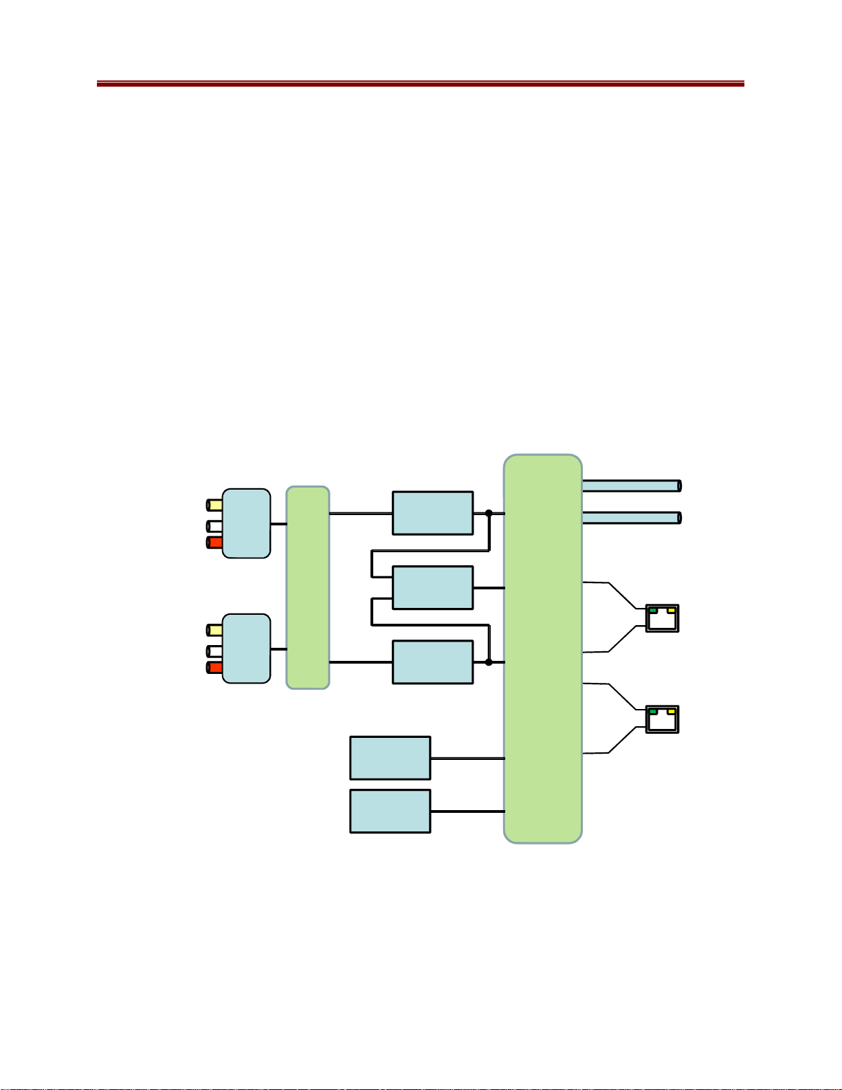
The overall architecture is depicted below.
Inputs
Composite/SDI
Unbalanced
Audio
Composite/SDI
Unbalanced
Audio
A/V
1
A/V
2
Switch
Encoder
Encoder
Test
Generator
Test
Generator
1
Mux
2
Switch
••• •••
Up t o 4
Up t o 4
Outputs
ASI 1
ASI 2
ETH1
ETH2
For the remainder of this manual, the term port for a physical input/output port (such as ASI or
Ethernet), and stream for a transport stream present in the port. ASI ports support only one
stream, while Ethernet ports support multiple streams.
8 9223SA-OM (V2.0)
Page 9
Connecting 9223-SA To DashBoard Network Remote Control
Note: The 9223-SA is functional with all DashBoard versions, however GUI display response is
optimized using version 3.0.0. Current DashBoard versions 4.0.0 and 4.1.0 may result in GUI
pages taking more time to update.
DashBoard™ allows openGear® frames and their cards to be remote-controlled using a PC or
Mac via a standard Ethernet connection. The DashBoard™ software can be downloaded from the
Cobalt Digital Inc. website: www.cobaltdigital.com (enter “DashBoard” in the search window).
When connected to your network, the 9223-SA appears in DashBoard just like any other device
(similar to a frame).
1. Install the DashBoard software as described above. DashBoard is available for Windows,
Linux, and Mac OSX.
2. By default, the 9223-SA is configured with a factory IP address of 192.168.2.00 and a
subnet mask of 255.255.255.0. In order to perform the initial configuration, you will
need to configure the PC/Mac running DashBoard for an IP address in the same network.
We suggest you use 192.168.2.0. Once you gain access to the 9223-SA, you can
reconfigure its IP address to whatever value you require, or configure it to run DHCP.
3. Connect the PC/Mac running DashBoard and the 9223-SA to the same network. For
simplicity, even running an Ethernet cable between the two devices will work. The 9223SA has auto-crossover capabilities, so any Ethernet cable will work. Connect the cable to
either one of the Control/Monitor ports in the 9223-SA, as illustrated below:
4. The DashBoard application should automatically find the 9223-SA and display it in the
tree view on the left. If the 9223-SA is not automatically found, click on the re-query
button at the top of the DashBoard tree view, as shown below:
9 9223SA-OM (V2.0)
Page 10
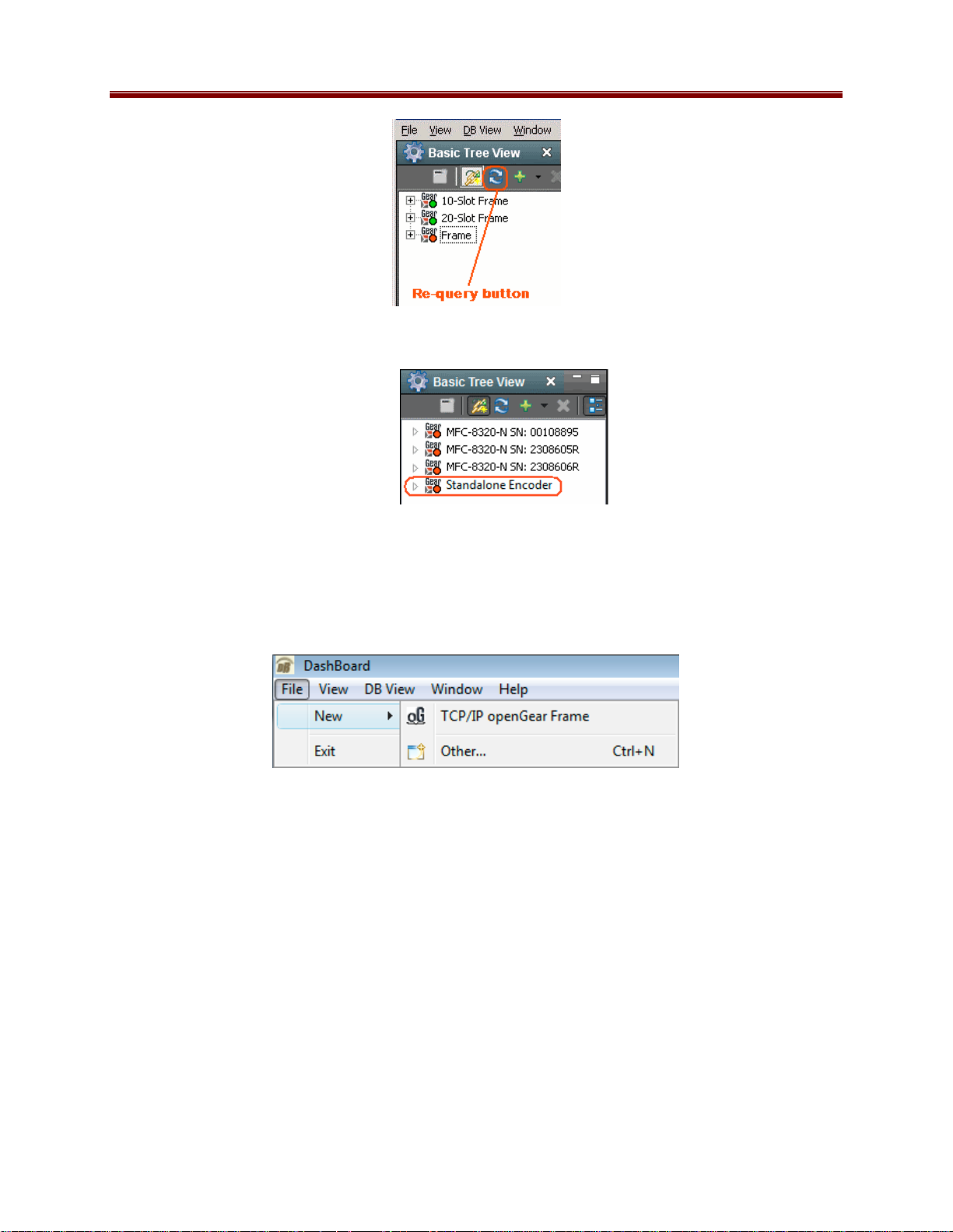
When the 9223-SA is found by DashBoard, it is identified as Standalone Encoder:
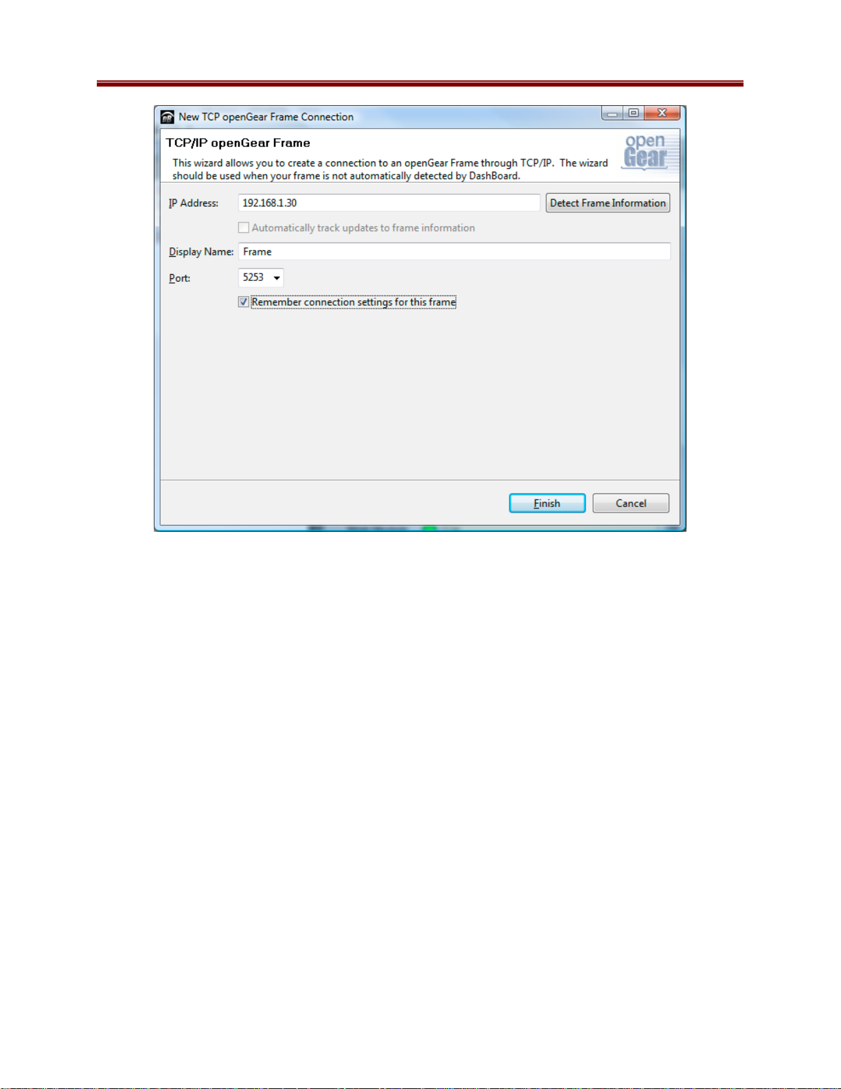
5. In the unlikely case that the 9223-SA is not automatically found by DashBoard, you can
force a manual connection. Select File Æ New Æ TCP/IP openGear Frame, enter the
IP address of the 9223-SA, and click on Finish:
10 9223SA-OM (V2.0)
Page 11
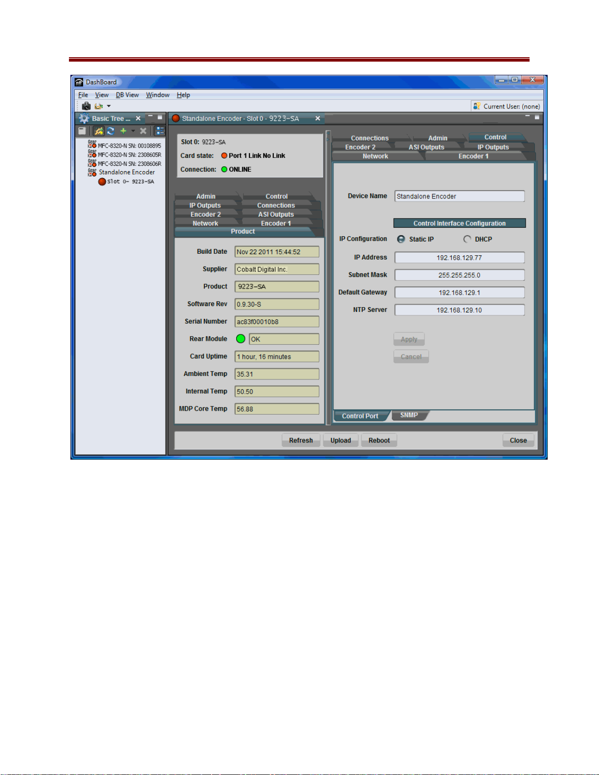
6. When the 9223-SA is available on DashBoard, open its user interface (by double-clicking
on Standalone Encoder to open it, and then on the device in slot 0). Go to the Control
tab on the right; you can now configure the IP address of the 9223-SA as desired. You
can also rename the device if you wish.
11 9223SA-OM (V2.0)
Page 12
7. The two control ports in the 9223-SA are intended for redundancy. You can connect
either one of them (or both) to your control network. The 9223-SA will use whatever
port is connected to respond to control operations.
12 9223SA-OM (V2.0)
Page 13

Indicators and Switches
Front Panel Indicators
• STAT LED: indicates the overall status of the unit.
Green
Red
Initially, this LED will be red until operation starts. At that point, it will turn green if
there is no active alarm or stay red if there is at least one alarm.
• PWR LED:
Green
Red
• VID 1 and VID 2 LEDs
LED off
LED flashing
– flashing once per second
– flashing 2x per second
– flashing 4x per second
No active alarm
At least one critical alarm present
Power OK
No power
no video signal detected, or input not
configured
Input video is SD
Input video is HD
Input video is 3G (e.g., 1080p5994)
• AS1 1 and ASI 2 LEDs:
LED off
LED flashing
• ETH/CTL 1 and ETH/CTL 2 LEDs: these indicate the status of the corresponding
transport Ethernet connection.
Green LED
– LED off
– LED on
Yellow LED
– LED off
– LED Flashing
• ENC 1 and ENC 2 LEDs:
LED off
LED flashing
ASI output port is disabled
ASI output port is configured and enabled
No link
Link OK
No activity (transmit and/or receive)
Port is currently transmitting and/or
receiving
Corresponding encoder channel is either
disabled, not running because of no input,
or in HLS or Direct HTTP mode.
Corresponding encoder channel is running
and outputting through ASI, UDP or RTP.
13 9223SA-OM (V2.0)
Page 14
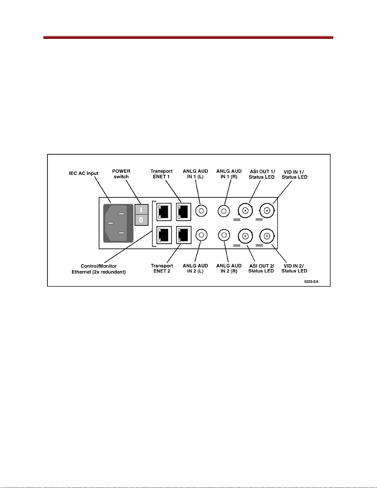
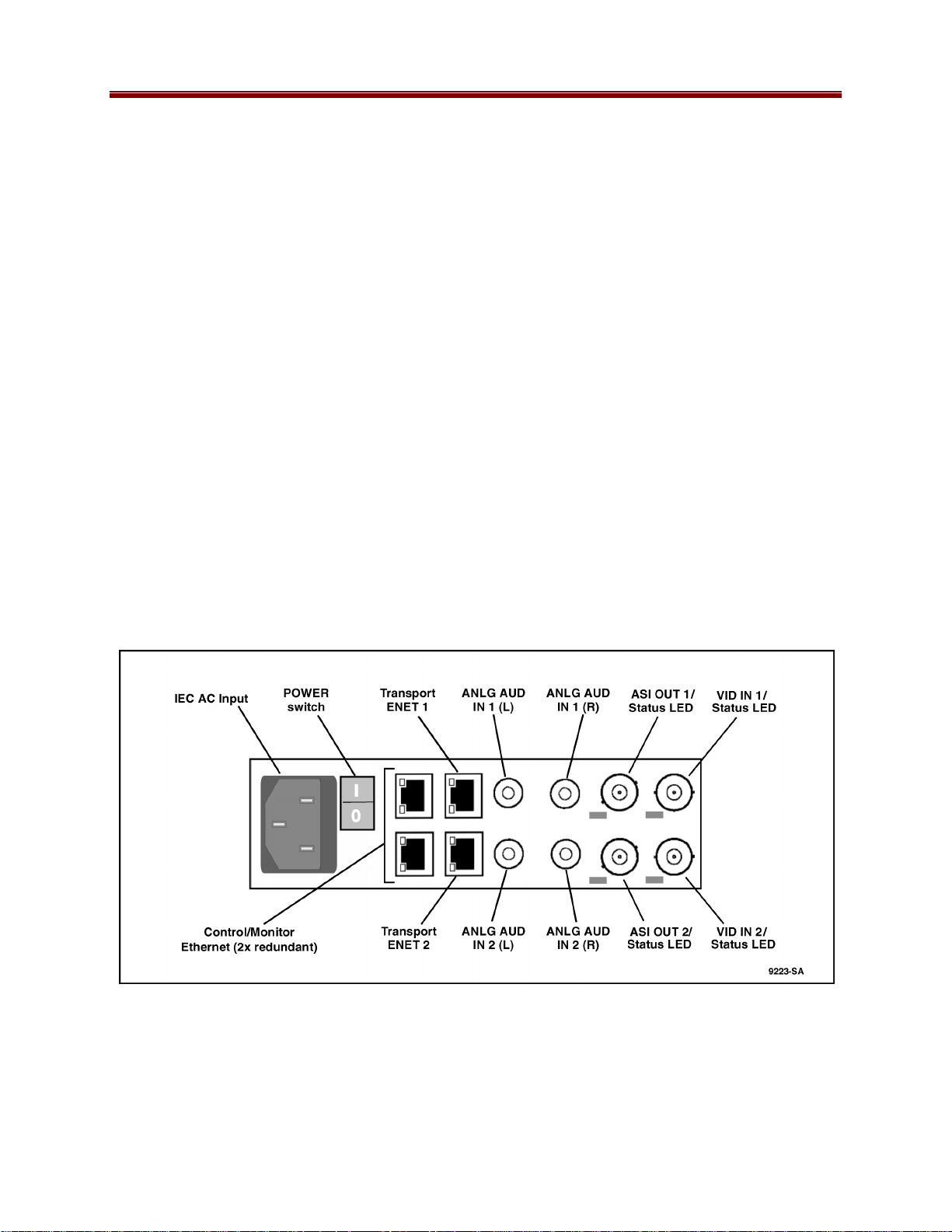
Rear Panel Controls, Indicators, and Connectors
The 9223-SA rear panel is depicted below. It includes two software-configurable
Composite/SDI video inputs on standard BNC connectors, two ASI output ports on standard
BNC connectors, four unbalanced analog audio inputs on standard RCA connectors, and two
100/1000 Mb/s Ethernet ports on standard RJ-45 connectors.
The VID IN 1 / VID IN 2, ASI OUT 1 / ASI OUT 2, and ENET 1 / ENET 2 ports are equipped
with LEDs that mirror the front-panel status respectively described in Front Panel Indicators for
these ports.
Note: Unless specified otherwise, “Ethernet” settings, connections, and controls in the remainder
of this manual refer to the transport (video stream) Ethernet interfaces carried over the ENET 1
and/or ENET 2 transport ports. The Control/Monitor ports are typically used only for unit
network remote control (such as DashBoard).
14 9223SA-OM (V2.0)
Page 15

9223-SA Operation and Management
The 9223-SA is configured using the free DashBoard™ application, which is available for
Windows, Apple OS X, and Linux.
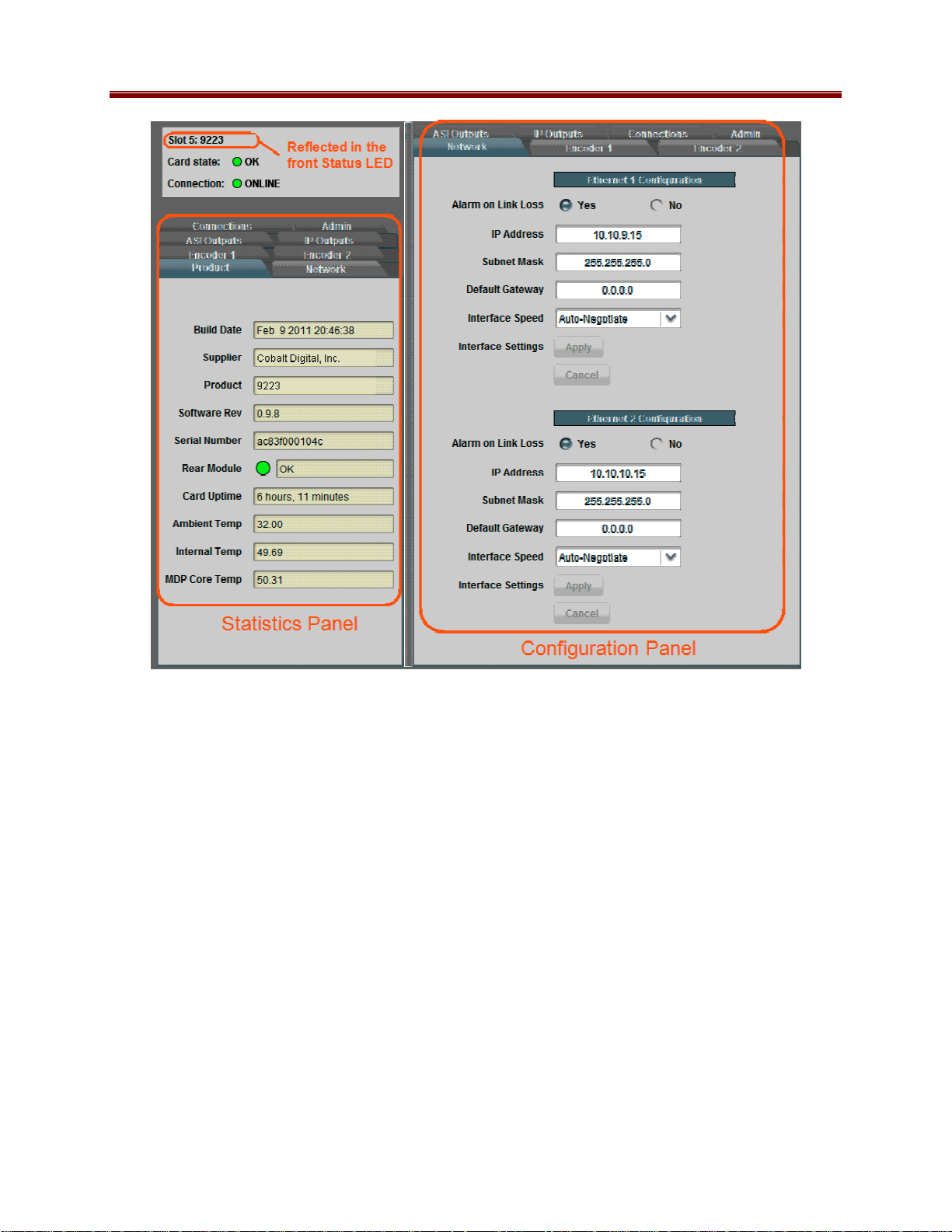
The 9223-SA user interface is depicted below. As with any openGear™ device, it is divided into
a statistics panel on the left, and a configuration panel on the right. Each panel has multiple tabs,
corresponding to the various functions of the unit. Note that the Card State (device state) alarm
indicator is also reflected in the green/red STAT LED on the front panel. The STAT LED will
be green when Card State is green or yellow, and will be red when Card State is red.
The following tabs are available:
• Product: this tab provides general information for the unit, including firmware version,
uptime, temperatures, and other parameters. It appears only on the Statistics panel.
• Network: this tab is used to configure the IP addresses and network information for the
transport Ethernet ports. The statistics side of the panel includes some additional
information such as link state.
• Encoder 1, Encoder 2: these tabs are used to configure the two encoder channels.
• ASI Outputs: this tab is used to configure/monitor the ASI ports.
• IP Outputs: this tab is used to configure/monitor the IP Output ports. The configuration
panel provides the facilities to create, manage and delete ports; the statistics panel
includes transmission status information.
• Connections: this tab is used to configure/monitor connections. The configuration panel
provides facilities to create, edit and delete connections; the statistics panel provides a
table where the status of all the connections in the unit can be inspected at a glance.
• Admin: this tab is used for general administrative functions, such as firmware upgrades,
licensing, logs, and configuration management. The Test Packet Generator configuration
is also found under this tab.
15 9223SA-OM (V2.0)
Page 16
16 9223SA-OM (V2.0)
Page 17

Product Tab
The Product Tab contains basic information about the 9223-SA.
The following information is available:
• Build Date: Date the firmware image was built.
• Supplier: Cobalt Digital Inc.
• Product: 9223-SA.
• Software revision: This indicates the firmware revision currently running. The format is
Major Version • Minor Version • Build Number.
• Serial Number: This is the serial number of this particular 9223-SA.
• Card Uptime: Indicates how long the unit has been running since it was last rebooted.
• Ambient Temperature: Temperature, in degrees Cesius, of the unit internal case
ambient temperature.
• Internal Temperature: Temperature, in degrees Cesius, adjacent to the unit PCB rear.
• MDP Core Temperature: Temperature, in degrees Cesius, of the core MediaStorm
processing element.
17 9223SA-OM (V2.0)
Page 18
Network Tab
The Network Tab allows for configuration/monitoring of the two video transport Ethernet ports
(Transport ENET 1 and Transport ENET 2).
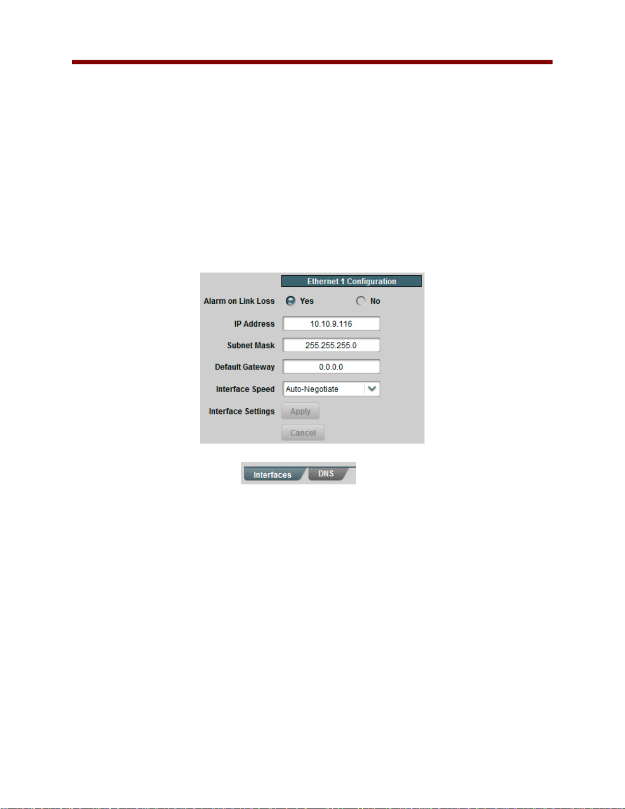
Network Configuration Tab
The Network Configuration Tab is used to set the individual parameters for each of the Ethernet
ports.
• The Interfaces tab is used to set the individual parameters for each of the streaming
Ethernet ports.
• The DNS tab is used to optionally configure DNS servers.
Configurat ion Tabs
Note: RTMP support requires that the device be capable of Domain Name Resolution (DNS
support), as many CDNs use DNS-based load-balancing.
The following parameters can be configured:
• Alarm on Link Loss: If set to Yes, the unit will raise an alarm if this Ethernet interface
looses link. The Card State indicator in DashBoard™ and the front panel STAT LED
will both be red. If set to No, the unit will still report loss of link in the Statistics page
but no alarm will be raised. It is recommended that the alarm for ports that are in use be
turned on; only turn it off if you do not plan to connect that port to a network.
• IP Address: Enter the desired IP address for this Ethernet port.
• Subnet Mask: Enter the desired subnet mask for this Ethernet port.
• Default Gateway: Enter the desired default gateway for this Ethernet port, or 0.0.0.0 if
no gateway is available.
18 9223SA-OM (V2.0)
Page 19
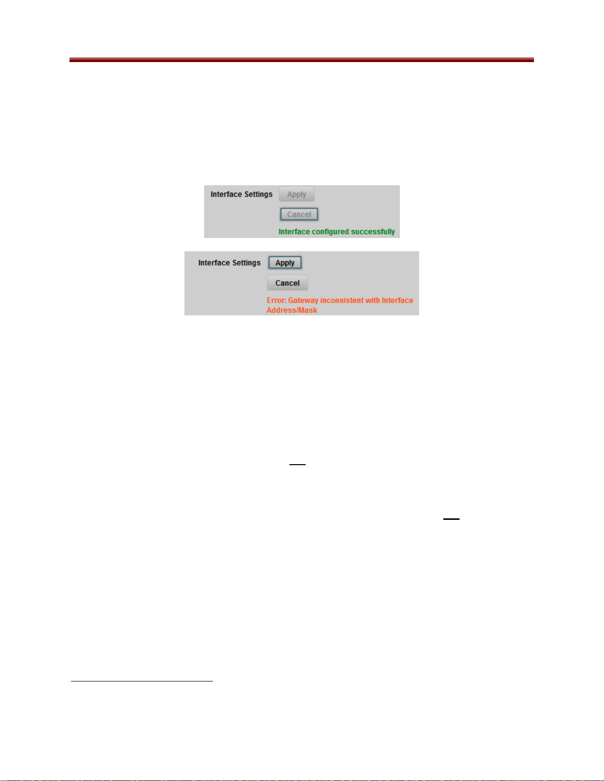
• Interface Settings: If you make any changes to the IP Address, Subnet Mask and/or
Default Encoder fields, the Apply and Cancel buttons become active. The changes only
take effect when you press the Apply button. Pressing the Cancel button reverts the
fields back to their original values. Note that the 9223-SA will check the consistency of
the data entered and will reject invalid combinations (i.e., combinations where the
gateway is outside the interface subnet). Once the Apply button is pressed, a status
message appears just below the Cancel button, as follows:
• Interface speed: Configures the speed of the interface. The 9223-SA Ethernet
interfaces only support two modes: 100 Mb/s Full-Duplex and 1 Gb/s Full-Duplex1.
o Auto-Negotiate: The Ethernet port will auto-negotiate the speed.
o 100 Mb/s Full-Duplex: Force the port to 100Mb/s Full-Duplex mode. Note that
the port will still perform auto-negotiation, but it will only advertise this mode.
o 1Gb/s Full-Duplex: restrict the operation to 1Gb/s Full-Duplex mode. Note that
the port will still perform auto-negotiation, but it will only advertise this mode.
Notes:
o If the 9223-SA streaming Ethernet interfaces are connected to a 10 Mb/s switch,
hub, or network feed, link will not be established and the port will not recognize
the connection.
o If you select 100 Mb/s Full-Duplex or 1 Gb/s Full-Duplex and the
corresponding streaming Ethernet interface is connected to a switch, hub or
network feed that does not support the selected speed, link will not be established
and the port will not recognize the connection.
o If the interface speed is set to Auto-Negotiate, the streaming Ethernet port will
allow link to be established in 100 Mb/s Half-Duplex mode. However, this will
be flagged as a warning.
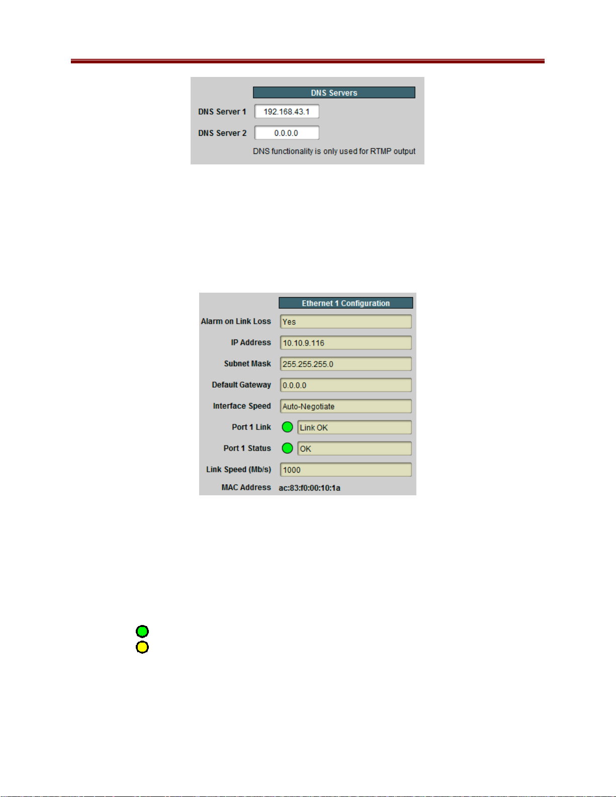
Network Configuration DNS Tab
The DNS tab allows manual configuration of up to two DNS servers. They do not need to be in
the same subnetwork as the streaming ports, as long as at least one default gateway is configured.
DNS is only used in conjunction with the RTMP output functionality. If you are not using
RTMP, there is no need to configure DNS servers.
1
Support for 10 Mb/s and Half-Duplex modes has been discontinued, as these are unsuitable for MPEG transport
over IP applications. Moreover, any modern switch supports at least 100 Mb/s Full-Duplex.
19 9223SA-OM (V2.0)
Page 20
DNS server configuration takes effect immediately, as soon as the information is entered.
DNS Servers configured in the Control Tab have priority over servers configured here.
Network Statistics Tab
The Network Statistics Tab reports the current IP configuration of each transport Ethernet port,
as well as their link state and running status.
The following parameters are reported in the Network Statistics tab:
• Alarm on Link Loss: Reports the current setting of this parameter.
• IP Address: Reports the current IP Address for the port.
• Subnet Mask: Reports the current Subnet Mask for the port.
• Default Gateway: Reports the current Default Gateway for the port.
• Interface Speed: Reports the current setting for this parameter.
• Port 1/2 Link: This indicator has the following states:
o Link OK: The port has established link with the network connection.
o Half-Duplex Link: The port is set to Auto-Negotiate, and it has achieved
100 Mb/s Half-Duplex link with the network connection. We do not consider HalfDuplex links suitable for video communication. The port will operate, but we
recommend that this be addressed. If Alarm on Link Loss is set to Yes, the
20 9223SA-OM (V2.0)
Page 21

Dashboard™ Card State will be yellow if there are no higher-priority alarms
present.
No Link: The port does not currently have link. If Alarm on Link Loss is set to
o
Yes, the DashBoard™ Card State will be red and the front panel STAT LED will
also be red. If Alarm on Link Loss is set to No, this indicator will still be red, but
the alarm will not propagate.
• Port 1/2 Status: This indicator is the port overrun status. It has the following states:
o
OK: The port is operating normally.
o TX Overflow: In the current configuration, the IP outputs are attempting to
transmit more than the port capacity (i.e., the overall output data for this port
exceeds the interface speed of 100 Mb/s or 1 Gb/s). The DashBoard™ Card State
will be red and the STAT LED will also be red. In this case, reduce the output bit
rate (either by reducing the encoder bit rates or by removing output ports). If this
indicator is red, data is being dropped.
• Link Speed (Mb/s): This parameter reports the actual speed negotiated with the switch
for the port. If the port has no link, the value reported here is zero.
• MAC Address: This reports the MAC address of the Ethernet port.
Encoder 1, Encoder 2 Tabs
The Encoder 1/Encoder 2 Tabs are used to configure/monitor the individual encoder channels.
The parameters in these two tabs are identical.
Encoder Configuration Tab
The Encoder Configuration Tab is further divided into the following 3 tabs:
• Basic Tab: contains the more important configuration parameters, which all users are
likely to change.
• Advanced Tab: contains the advanced configuration parameters, which do not
necessarily need to be changed.
• Connections Tab: allows the creation of connections between this encoder and the ASI
and IP output ports.
Confi gurati on Tabs
In general, the encoder user interface will change as a function of the parameter selections made,
to remove illegal parameter combinations.
Selections made in any of the encoder configuration screens do not take effect until the Apply
button is pressed. If you wish to discard the changes made to the user interface, press the Cancel
button. The Apply/Cancel buttons are present in all the tabs and will be grayed out until
21 9223SA-OM (V2.0)
Page 22

changes are made. At any given point in time, the currently running encoder configuration can
be inspected in the Encoder Statistics Tab, described later in this document.
Video Input Auto-Detection
The 9223 can be set to auto-detect the video input signal, and self-configure for the incoming
resolution and frame rate. This feature allows the encoder to operate in situations where the
video signal can change over time (for example, at the output of a video switch). The 9223 is
even capable of automatically recognizing whether a signal is SDI or composite, and the video
standard for composite signals.
The following points should be considered when using video input auto-detection:
• The available output scaling options are limited, since some options are specific to some
input resolutions.
• If the encoder is not licensed for a given configuration, it will stop encoding if the input
video signal switches to a value that requires this configuration. For example, an SD
encoder configured to output the same resolution as the input will stop if the input signal
switches to HD.
• If the encoder is configured with auto-detection and SDI embedded audio, it will fall
back to analog audio if it detects a composite video signal. If your input can switch
between SDI and composite, either use analog audio for all signals, or make sure that the
corresponding analog audio signal is present at the encoder unbalanced audio inputs
when the video is a composite signal.
Multiple Audio Support
The 9223 can be licensed to offer up to two additional MPEG-1 Layer II audio channels,
regardless of the number of installed encoders. These additional audio channels can be
associated with the first or second encoder. Moreover, a dual-channel encoder can be configured
as a single-channel encoder with combined audio. The following combinations are supported:
• Single Channel Encoders: support for 1, 2 or 3 audio stereo pairs, as follows:
o First stereo pair:
MPEG-1 Layer II, AAC-LC or Dolby Passthrough support
Valid inputs: analog unbalanced audio, SDI embedded (SDI signals only)
o Second stereo pair:
MPEG-1 Layer II support only
Valid inputs: second analog unbalanced audio, SDI embedded (SDI
signals only)
o Third stereo pair (only available for SDI inputs):
MPEG-1 Layer II support only
Valid input: SDI embedded
• Dual Channel encoders: support for 1 or 2 audio stereo pairs per encoder channel, as
follows:
o First stereo pair:
MPEG-1 Layer II, AAC-LC or Dolby Passthrough support
Valid inputs: analog unbalanced audio, SDI embedded (SDI signals only)
22 9223SA-OM (V2.0)
Page 23

o Second stereo pair (only available for SDI inputs):
MPEG-1 Layer II support only
Valid input: SDI embedded
• Dual Channel encoders can be configured to have one encoder channel with 3 audio
stereo pairs, and another encoder channel with 1 audio stereo pair, as follows:
o Encoder with 1 stereo pair:
MPEG-1 Layer II, AAC-LC or Dolby Passthrough support
Valid inputs: analog unbalanced audio, SDI embedded (SDI signals only)
o Encoder with 3 stereo pairs:
First stereo pair:
• MPEG-1 Layer II, AAC-LC or Dolby Passthrough support
• Valid inputs: analog unbalanced audio, SDI embedded (SDI
signals only)
Second stereo pair (only available for SDI inputs):
• MPEG-1 Layer II support only
• Valid input: SDI embedded
Third stereo pair (only available for SDI inputs):
• MPEG-1 Layer II support only
• Valid input: SDI embedded
• Dual Channel encoders with combined audio: support for up to 4 audio stereo pairs per
board, as follows:
o First stereo pair:
MPEG-1 Layer II, AAC-LC or Dolby Passthrough support
Valid inputs: analog unbalanced audio, SDI embedded (SDI signals only)
o Second stereo pair:
MPEG-1 Layer II, AAC-LC or Dolby Passthrough support
Valid inputs: second analog unbalanced audio, SDI embedded (SDI
signals only)
o Third stereo pair (only available for SDI inputs):
MPEG-1 Layer II support only
Valid input: SDI embedded
o Fourth stereo pair (only available for SDI inputs):
MPEG-1 Layer II support only
Valid input: SDI embedded
23 9223SA-OM (V2.0)
Page 24

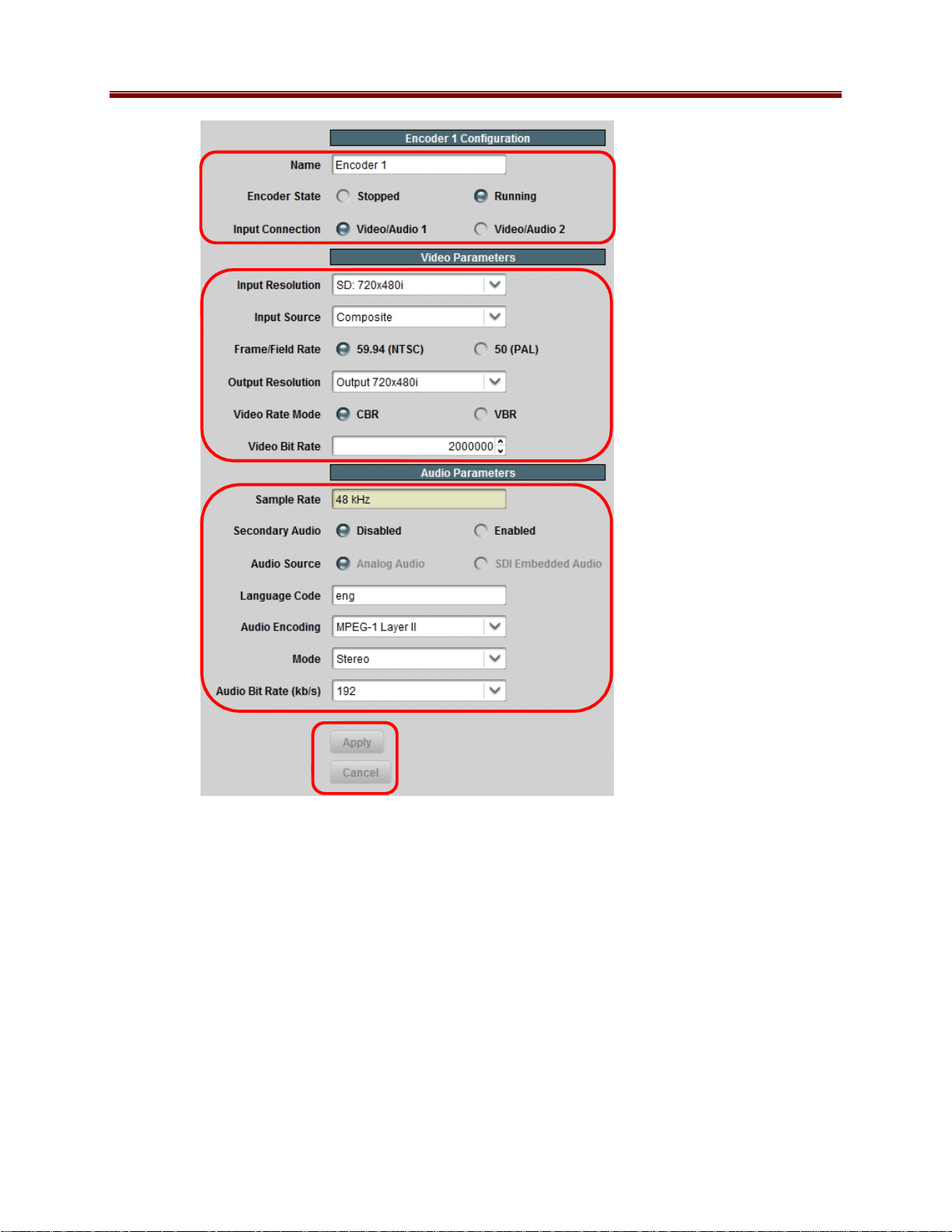
Encoder Basic Configuration Tab
The Encoder Basic Configuration Tab, shown below, is divided into three general areas:
• General Configuration: generic configuration parameters.
• Video Configuration: parameters related to video encoding.
• Audio Configuration: parameters related to audio encoding.
Note that the basic configuration tab may look different from what is depicted below, as the
parameters may change (or appear/disappear in the GUI) based on the device’s configuration and
the parameter choices made.
Basic Tab – General Configuration
• Name: All 9223-SA encoders and outputs can be assigned a user-defined name. This
name is used to identify the encoder later when making connections. Use any descriptive
name suitable for your application, or accept the default.
• Encoder State: This control allows you to start/stop an encoder. This control needs to be
set to Running for normal operation.
• Input Connection: This control selects which of the two rear panel inputs is to be
connected to this encoder. The 9223-SA can run both encoders from the same input. The
default is to run Encoder 1 from Video/Audio 1 and Encoder 2 from Video/Audio 2, but
all combinations are allowed. Note that the parameters presented in the Video
Configuration section may change if this selection changes (for example, if you switch
the encoder from a Composite input to an SDI input).
24 9223SA-OM (V2.0)
Page 25
General
Configuration
Video
Configuration
Audio
Configuration
Apply/Cancel
Configur atio n Changes
Basic Tab – Video Configuration
The 9223 is capable of automatically identifying the video signal present in the selected input
connection. The detected signal is reported in the Encoder Statistics Tab. Additionally, the
encoder can also be set to auto-configure its input based on the detected signal:
• Video Input Settings: This parameter selects whether or not the encoder will auto-
configure based on the detected video input signal.
o Manual Selection: The input signal must be correctly selected using the Input
Resolution, Input Source, and Field/Frame Rate controls for the encoder to run.
If the input signal does not match the settings, the encoder will not run.
25 9223SA-OM (V2.0)
Page 26
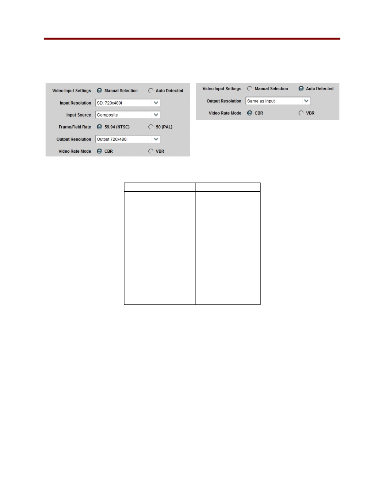
o Auto Detected: The encoder will auto-detect the input signal, and automatically
configure for it if it is a supported signal. The Input Resolution, Input Source,
and Field/Frame Rate controls are not displayed.
The following table lists the supported input video signals:
Composite Signals SDI Signals
NTSC
NTSC 4.43
PAL B/D/G/H/I/N
PAL-M
PAL-Nc
SECAM
720×480i59.94
720×576i50
1280×720p50
1280×720p59.94
1280×720p60
1920×1080p23.98
1920×1080p24
1920×1080i50
1920×1080i59.94
1920×1080i60
1920×1080p50
1920×1080p59.94
1920×1080p60
If Video Input Settings is set to Manual Selection, the Input Resolution, Input Source and
Field/Frame Rate parameters are displayed and must be set to match the incoming video signal.
• Input Resolution: Select the resolution of the input video signal. The following four
choices are available:
o SD: 720×480i (this will be presented as 720×576i if Field/Frame Rate is set to
PAL).
o HD: 1280×720p
o HD: 1920×1080i
o HD: 1920×1080p
• Input Source: Select the input source type. This control is available only if the Input
Resolution is set to SD. In this case, the options will be Composite or SD-SDI. If
Input Resolution is set to any of the HD values, this control will not be selectable, and
will show the appropriate type of input (HD-SDI for 1280×720p and 1920×1080i, and
3G-SDI for 1920×1080p).
26 9223SA-OM (V2.0)
Page 27
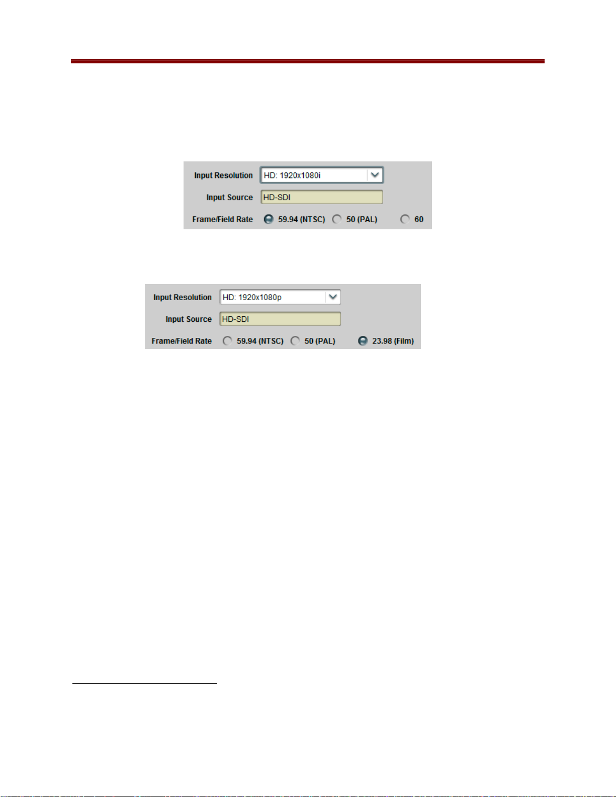
• Field/Frame Rate: Select to match your source. For all input resolutions, the supported
options always include 59.94 (for NTSC-based systems) and 50 (for PAL-based
systems). Some resolutions have support for additional frame rates, as follows:
o If you select the 1920×1080i or 1280×720p resolutions, this field will also include
an option for a field rate of 60, used by same cameras:
o If you select the 1920×1080p resolution, this field will also include an option for a
frame rate of 23.98 (Film):
• Output Resolution: Select the desired output resolution. The values in this drop-down
list are a function of the Input Resolution and the Frame/Field Rate. Also, please note
that some resolutions require additional licensing for the encoder. The following
resolutions are offered:
o Same as the input (no scaling)
o ¾ scaling from the input
o Low resolutions: 480×270, 320×240, and 320×180, progressive, at half and
quarter frame rates (not available for 1080p inputs)
o HD inputs can be scaled (and re-interlaced if necessary) to SD resolution,
anamorphic (not available for 1080p inputs)
o 1080i, 720p and SD inputs can be converted to SD resolution, with progressive
frame rates (ideal for computer displays), as follows:
1080i59.94, 720p59.94, and 480i59.94 are converted to 720×480p29.97
1080i60 and 720p60 are converted to 720×480p30
1080i50 and 720p50 are converted to 720×576p25
The conversions from HD resolutions are done using anamorphic scaling.
2
o 1080i, 720p and SD
inputs can be scaled to 640×360, with progressive frame
rates, as follows:
1080i59.94 and 480i59.94 are converted to 640×360p29.97
720p59.94 is converted to 640×360p59.94
1080i50 and 576i50 are converted to 640×360p25
720p50 is converted to 640×360p50
2
By default, SD signals have a 4:3 aspect ratio, unless they are derived from an HD source with anamorphic scaling.
The 640×360 resolution is intended for 16:9 content. Scaling SD to 640×360 should only be done if the SD signal is
anamorphic to start with, otherwise the resulting encoded signal will have an incorrect aspect ratio.
27 9223SA-OM (V2.0)
Page 28
o HD 1080i inputs can be scaled to ¼ resolution (960×540), with the same
incoming frame rate
o SD inputs can be horizontally cropped to 704 pixels or horizontally scaled to 640
pixels
If Video Input Settings is set to Auto Detected, the following options are offered in this
parameter:
o Same as Input: the encoder will produce a signal that has the same resolution and
frame rate as the input (no scaling).
o Scale 3/4 Horizontal: the encoder will scale down the image horizontally by 3/4.
The frame rate will not be changed.
o Scale to 640×360p: the encoder will scale the input video to 640×360. The frame
rate will be the same as the input, but interlaced inputs will be de-interlaced (for
example, 1920×1080i60 will yield 640×360p30). This resolution is not available
for 1920×1080p inputs at any frame rates; the encoder will fall back to 3/4
horizontal scaling in this case.
o Scale to 480×270p, Scale to 320×240p, Scale to 320×180p: the encoder will
scale the input video to the selected resolutions. Interlaced inputs will be deinterlaced as described above. Progressive inputs will be encoded at half frame
rate. This resolution is not available for 1920×1080p inputs at any frame rates;
the encoder will fall back to 3/4 horizontal scaling in this case.
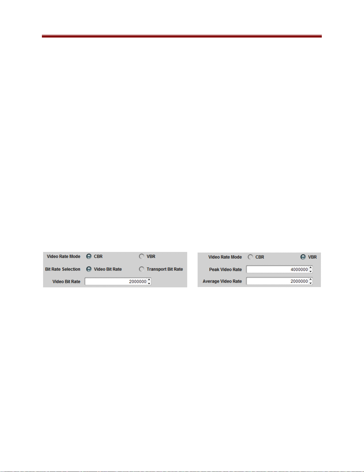
• Video Rate Mode: This controls whether the video elementary stream is CBR or VBR.
The video bit rate setting varies according to this selection, as shown below.
• Bit Rate Selection: This field is shown only if the encoder is set to CBR mode, and
allows the user to specify either the video bit rate, or the transport bit rate. The transport
bit rate includes audio, video, tables, NULL packets, and various overheads. In some
situations, such as for example, RF links of fixed capacity, it is more convenient to
specify the transport rate (i.e., the final bit rate “in the wire”), and let the encoder
compute the corresponding video bit rate to yield the desired transport rate. In other
situations, such as IPTV deployments, it is more convenient to simply specify the video
bit rate and let the encoder compute the final transport rate. Note that this control is not
available in the OTT protocol modes. The controls displayed vary according to this
selection:
28 9223SA-OM (V2.0)
Page 29
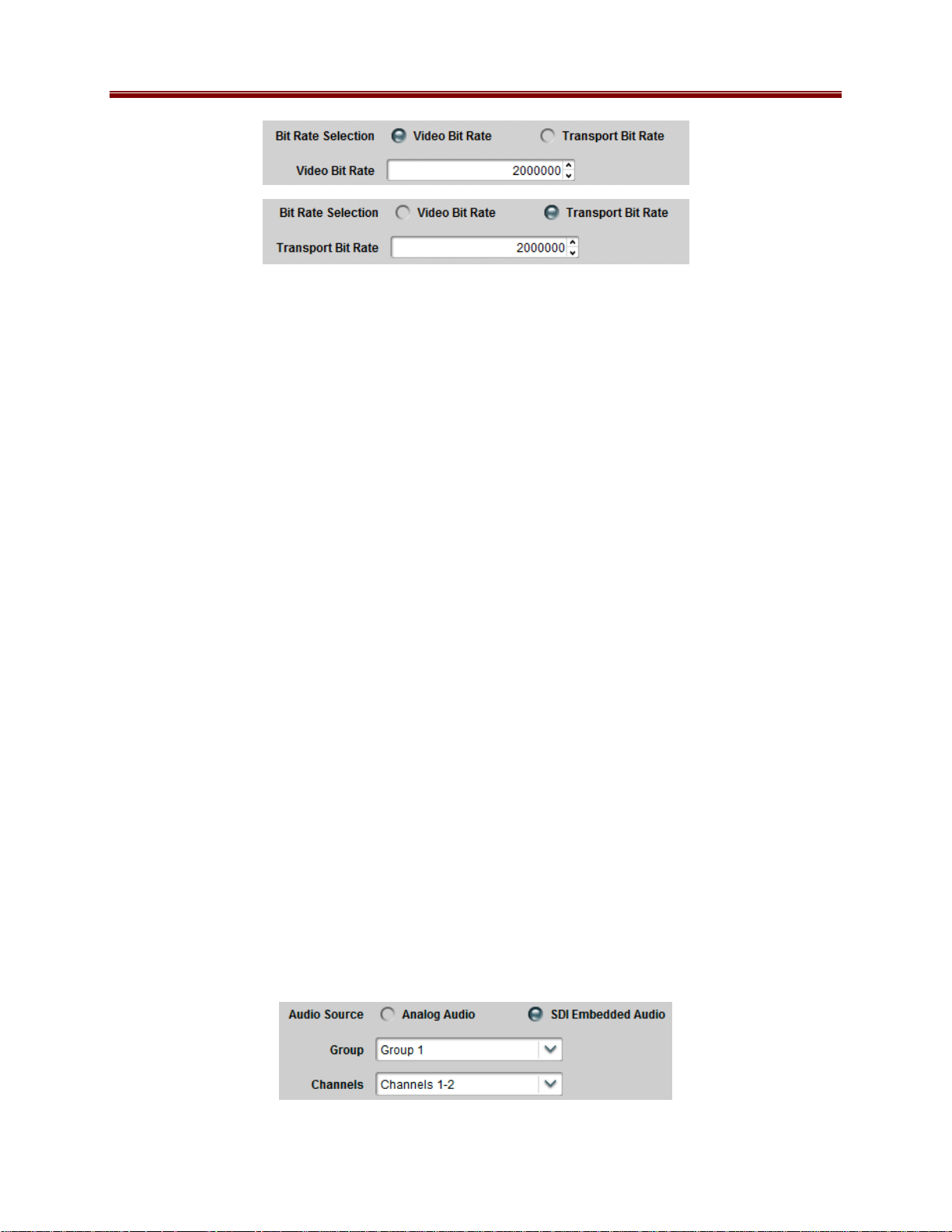
• Video Bit Rate: This field is shown only if the encoder is set to CBR mode and the Bit
Rate Selection control is set to Video Bit Rate. It determines the video elementary
stream bit rate, expressed in bits/second. Note that the bit rate resolution is
1000 bits/second.
• Transport Bit Rate: This field is shown only if the encoder is set to CBR mode and the
Bit Rate Selection control is set to Transport Bit Rate. It determines the overall
transport stream bit rate, with a resolution of 1000 bits/sec; the encoder will calculate the
appropriate video bit rate the yield the desired transport rate. Please note that all
transport rates are achievable; in particular, the encoder may not be able to achieve very
low transport rates if the audio bit rates are high. In these cases, the actual transport rate
output by the encoder will be higher than the configured value. The actual transport rate
is displayed in the Encoder Statistics Tab, after the Apply button has been pressed. At
that point, the actual encoder video bit rate can be found in the Encoder Statistics Tab,
under the Basic bottom tab.
• Peak Video Bit Rate, Average Video Bit Rate: These two fields are shown only if the
encoder is set to VBR mode, and determine the desired average and acceptable peak bit
rates for the video elementary stream. The peak video bit rate must be between 2.0 and 2
times the average bit rate; the user interface will enforce these limits automatically (i.e., it
will update either the average or peak to be consistent with the value being entered). For
both of these parameters, the resolution is 1000 bits/sec.
Basic Tab – Audio Configuration
• Audio Source: This parameter selects the audio source. The options are Analog Audio,
directing the encoder will to use the analog right/left audio channels connected to the rear
panel, and SDI Embedded Audio, directing the encoder to extract embedded audio from
the SDI input. If the video Input Source (see Basic Tab – Video Configuration) is set to
Composite, this parameter is grayed out and forced to Analog Audio. It will be
selectable only if the video input source is one of the SDI variations. When SDI
Embedded Audio is selected, additional configuration options become available, as
shown below.
29 9223SA-OM (V2.0)
Page 30
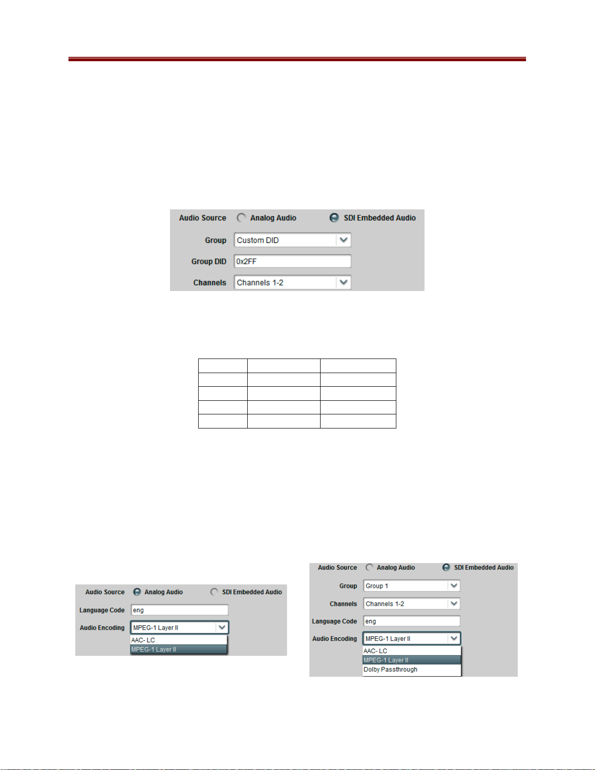
• Group, Channels: SDI embedded audio is typically divided into four groups (denoted by
Group 1 to Group 4); each group has four mono channels (2 stereo pairs), denoted by
Channels 1-2 and 3-4. These controls allow the selection of the desired group and
channel pair. In the large majority of the cases, the first stereo pair is in Group 1,
Channels 1-2, the second stereo pair is in Group 1, Channels 3-4, and so on. The Group
selection has one additional choice, labeled Custom DID. This allows the encoder to use
a non-standard embedded audio DID (this quite uncommon). If Custom DID is selected,
a new configuration option becomes available, where the DID can be entered:
• Group DID: Enter the desired Group DID, in hexadecimal. Note that the entry will be
immediately validated and rejected if invalid. As a reference, the table below contains
the standard DIDs built into the system for Groups 1 to 4.
Group SD-SDI DID HD-SDI DID
Group 1 0x2FF 0x2E7
Group 2 0x1FD 0x1E6
Group 3 0x1FB 0x1E5
Group 4 0x2F9 0x2E4
• Language Code: This parameter represents the 3-letter ISO 639-2 language code for the
audio, to be placed in the audio language descriptor in the PMT.
• Audio Encoding: This parameter selects the audio encoding algorithm. The available
choices depend on the Audio Source selection. For Analog Audio, the choices are
MPEG-1 Layer II and AAC-LC. For SDI Embedded Audio, the Dolby Passthrough
option is offered in addition to the previous choices. Note that AAC-LC requires
additional licensing. The two variants for this control are depicted below.
30 9223SA-OM (V2.0)
Page 31

• Mode: The available choices for this parameter depend on the Audio Encoding
selection, as follows:
o MPEG-1 Layer II: the available modes are Stereo or Single Channel. If you
select Single Channel (Mono), only the audio connected to the Left input will be
encoded.
o AAC-LC: the available modes are Stereo, Mono, or Dual Mono. If you select
Mono, only the audio connected to the Left input will be encoded.
o Dolby Passthrough: This parameter is not displayed.
• Audio Bit Rate: The format of this parameter is a function of the Audio Encoding
setting. For MPEG-1 Layer II, this parameter is a drop-down list of valid discrete bit
rates; the values in the list are also a function of the Mode Setting. For AAC-LC, the
range is 112 to 512 kb/s for Stereo and Dual Mono, and 56 to 256 kb/s for Mono. This
parameter is not displayed for Dolby Passthrough as the 9223-SA will automatically
detect the incoming audio bit rate.
• Peak Audio Bit Rate: This parameter is only displayed for AAC-LC. It must be set at
least 1 kb/s higher than the Audio Bit Rate. The maximum value is 288 kb/s for Mono,
and 576 kb/s for Stereo and Dual Mono.
• Sample Rate: This field is for information purposes only. The 9223-SA only supports
48 kHz audio sample rate.
Basic Tab – Additional Audio Support
If the encoder is in a configuration where additional audio channels can be offered, a checkbox
to enable them will be presented in the GUI, as indicated below:
If the box is checked, additional fields will become available for configuring the additional audio
channel. These fields are the same as with the first audio channel. Note that, depending on the
configuration, the Audio Source selection may be grayed out.
31 9223SA-OM (V2.0)
Page 32

After the first additional audio is enabled, the encoder may offer a second additional audio
channel, as depicted below:
The second additional audio option will be offered in the following conditions:
• In a single-channel encoder, if the input signal type is SDI.
• In a dual-channel encoder, if the first additional audio is not being used by the other
encoder channel.
• In a dual-channel encoder, if secondary audio is enabled (see the next section).
Additional audio channels are only available if the Output Protocol in the Encoder Connections
Tab is set to ASI/IP Streaming.
32 9223SA-OM (V2.0)
Page 33

Basic Tab – Secondary Audio Support
A dual-channel 9223-SA can be configured to offer secondary audio support (i.e., a second audio
PID in the same program). If this function is available, it will be available in the audio section of
Encoder 1, as indicated below:
When Secondary Audio is set to Enabled, the Encoder 1 Audio Configuration section will
change as indicated below:
The individual controls work in the same manner as discussed before. Each audio channel can
be independently configured. As before, the SDI Embedded Audio option will only be available
if the Encoder 1 input selection is one of the SDI variants. The only input restriction is that,
when using Analog Audio, the signal connected to Video/Audio 1 will be the first audio channel,
and the signal connected to Video/Audio 2 will be the second audio channel.
33 9223SA-OM (V2.0)
Page 34

Support for secondary audio requires that both encoder channels in the unit be tied together.
When the Secondary Audio control depicted above is set to Enabled, Encoder 2 will be slaved
to Encoder 1. Its Basic Configuration Tab in this mode is depicted below:
Contr ols Slaved
to Encoder 1
Contr ols Shared
with Encoder 1
Encode r 2 Audi o
Inser tion Controls
The operation is as follows:
• The Encoder State and Input Selection controls are slaved to the corresponding controls
in Encoder 1. They will reflect the state of their Encoder 1 counterparts.
• The Input Resolution, Input Source and Field/Frame Rate controls are shared with
Encoder 1, and apply to whatever input port is selected. Changes here will be mirrored in
the corresponding parameters for Encoder 1.
• Encoder 2 can optionally share one or both audio channels from Encoder 1. This is
accomplished by checking Include Audio Ch1/2 boxes in the Audio Insertion Controls
displayed above.
Encoder Advanced Configuration Tab
The appearance of the Encoder Advanced Configuration Tab is a function of the choices made in
the
34 9223SA-OM (V2.0)
Page 35

Encoder Basic Configuration Tab. It is divided into four major areas:
• Video Parameters: these are advanced controls related to the encoding of the video.
• Closed Captioning: controls related to Closed-Captioning insertion. This section is not
shown if Field/Frame Rate in the Basic Tab – Video Configuration is set to PAL.
• Audio Parameters: these are advanced controls related to the audio subsystem.
• Mux Parameters: these are advanced controls related to audio/video multiplexing and
(P)SI tables.
Advanced Tab – Video Parameters
The Video Parameters section is shown below:
• GOP Mode: Select between Open GOP and Closed GOP. The normal setting is Open
GOP. Closed GOP is used for some storage applications; there is a very small negative
impact in video quality if Closed GOP is selected.
• Profile: This control has four options:
o Auto-Select: With this setting, the encoder will signal High Profile for HD and
Main Profile for SD.
o High Profile: With this setting, the encoder will always signal High Profile.
o Main Profile: With this setting, the encoder will always signal Main Profile.
o Baseline Profile: This setting will cause the encoder to go to Baseline Profile.
There will be a small loss of encoding quality. The GOP Structure control will
not be selectable in Baseline Profile.
• GOP Structure: Select between IBBP, IBP and IP. Selecting IBBP gives the best
video quality, but some low-end decoders require IP. If Profile is set to Baseline Profile,
this control will not be selectable and will be forced to IP.
Note that if the Output Resolution setting in the Basic Tab – Video Configuration is set to one
of the low resolutions (480×270, 320×240, or 320×180), the Profile and GOP Structure
controls will not be selectable; this section will appear as follows:
35 9223SA-OM (V2.0)
Page 36

Also note that if the Input Resolution setting in the Basic Tab – Video Configuration is set to
1920x1080p, the Profile and GOP Structure controls will not be selectable; this section will
appear as follows:
Advanced Tab – VBI/Ancillary Data Insertion
The 9223-SA can extract the following data types from the video input and insert them in the
compressed video output:
• Closed Captioning
• Active Format Description (AFD)
Closed Captioning
The Closed Captioning controls are only displayed if Field/Frame Rate in the Basic Tab –
Video Configuration is set to NTSC. The appearance of this control is also a function of the
Input Resolution and Input Source parameters, as depicted below.
The Closed Captioning controls are as follows:
• Enable CC: check this box to enable Closed-Captioning insertion. Closed Captions are
inserted in the video elementary stream, as per ATSC A/72. Both CEA-608 and
CEA-708 captions are supported.
• CC Source: this controls where the encoder extracts closed captions from. As depicted
below, this field may or may not be editable, depending on the input resolution and input
source. The options are:
o CEA-608 Line 21: this option can only be used for SD inputs. The encoder will
extract all the CEA-608 information from both fields of Line 21, if present.
o SMPTE-334 VANC: this option can only be used for SDI inputs. The encoder
will expect closed-captioning information in the VANC. Both CEA-608 and
CEA-708 modes are supported (and automatically detected).
36 9223SA-OM (V2.0)
Page 37

Closed-Captioning Disabled
Input Source: SD-SDI
Input Resolution: SD
Input Source: Composite
Input Resolution: SD
Input Source: HD-SDI or 3G-SDI
Input Resolution: HD
Active Format Description
The 9223-SA can extract Active Format Description (AFD) information from the incoming
video signal and insert it in the compressed bitstream. AFD information can be extracted from
the following sources:
• For SDI signals, AFD information can be present in the VANC as per SMPTE-2016-3.
This is the primary way of conveying AFD information on a professional video feed.
• For SD signals (either from Composite or SD-SDI sources), AFD information can be
synthesized from Wide Screen Signaling (WSS) data present in the VBI (line 20 for
NTSC signals, line 23 for PAL signals).
• The 9223-SA also has the option of inserting a user-defined AFD code (instead of
receiving it from the video input).
The AFD controls are as follows:
• Enable AFD: Check this box to enable AFD extraction and insertion. This control is
always available. AFD is inserted in the video elementary stream as per ATSC A/72 and
ETSI TS 101 154.
• AFD Source: This controls where the AFD information is coming from. The options
are:
o Line 20 WSS/Line 23 WSS: This option causes the encoder to synthesize AFD
information from WSS. It is available only if the input resolution is SD. It will
be displayed as Line 20 for NTSC and Line 23 for PAL. For PAL inputs, the
conversion follows ETSI TS 101 154 Appendix B.4.
o SMPTE-2016-3 VANC: This option causes the encoder to extract AFD from the
VANC. It is only available for SDI inputs.
o Manual AFD Selection: This option allows the user to specify a fixed AFD code
to be inserted. Any AFD information received from the input is ignored. This
37 9223SA-OM (V2.0)
Page 38

can be used to override the original AFD information, or when the video is being
scaled (e.g., when the input is HD and is being converted to SD).
• AFD Code: This control is displayed only when AFD Source is set to Manual AFD
Selection. It corresponds to the codes listed in SMPTE-2016-1, Table 1.
Composite
SD-SDI
HD
Advanced Tab – Audio Parameters
The Audio Parameters are divided into three subgroups, some of which vary (and may not be
present) according to the selections made in the
38 9223SA-OM (V2.0)
Page 39

Encoder Basic Configuration Tab. A sample of the Audio Parameters section is depicted below.
Analog Audio
Analog Audio
Parameters
Parameters
PMT Information
PMT Information
Audio Encoder
Audio Encoder
Specific Configuration
Specific Configuration
Analog Audio Parameters
These parameters are only displayed if Audio Source in Basic Tab – Audio Configuration is set
to Analog Audio. The parameters are:
• Audio Gain L (dB), Audio Gain R (dB): These controls allow an independent gain
adjustment for the left/right audio channels, from -7.0 dB to +7.0 dB, in steps of 0.5 dB.
• Audio Mute L, Audio Mute R: These controls allow muting of the left/right audio
channels.
A/V Sync Adjustment
This parameter can be used to provide a small amount of A/V sync adjustment, for cases where
the A/V sync in the input signal to the encoder is not correct. If, in the input signal, audio is
behind the video, you can use this parameter to compensate for up to 100 milliseconds. Note
that it is only available for MPEG-1 Layer II and AAC-LC encoding; it will not be displayed for
Dolby Passthrough.
• Audio Delay (ms): Use this to compensate for up to 100 milliseconds of audio delay in
the input signal. This setting will advance the audio in relation to the video by the
amount configured.
PMT Information
The Audio Type control is always available. Its meaning is:
39 9223SA-OM (V2.0)
Page 40

• Audio Type: determines the audio type in the PMT audio descriptor. This setting has no
actual impact on how the audio is encoded; it only affects its description in the PMT.
The choices are:
o Undefined: no further information. This is the most common setting.
o Clean Effects: indicates that the audio has no language.
o Hearing Impaired: indicates that the audio is prepared for the hearing impaired.
o Visual Impaired Commentary: indicates that the audio is prepared for the
visually impaired viewer.
If the Audio Encoding setting in the Basic Tab – Audio Configuration is set to Dolby
Passthrough, another parameter becomes available in the PMT Information section:
• Dolby PMT Type: this parameter controls how Dolby AC-3 audio is signaled in the
PMT. The two choices are:
o DVB: Dolby Audio is signaled as per ETSI TS 101 154 Appendix C (stream_type
0x06 with the AC-3 Descriptor from EN 300 468 annex D).
o ATSC: Dolby Audio is signaled as per ATSC A/53 Part 3 (stream_type 0x81).
However, the 9223-SA is currently unable to generate the ATSC AC-3
Descriptor.
If the Output Protocol in the Encoder Connections Tab is set to RTMP, the PMT Information
fields will not be displayed as RTMP does not use the Transport Stream container.
Audio Encoder Specific Configuration
The appearance of this control depends on the Audio Encoding setting in the Basic Tab – Audio
Configuration.
AAC-LC Configuration
MPEG-1 Layer II Configuration
The parameters are:
• CRC: Enables/Disables CRC insertion in the audio elementary stream. This is normally
left disabled (CRC off).
• Original/Copy: Controls the state of the Original/Copy flag in the audio elementary
stream. This setting does not affect the actual audio encoding.
40 9223SA-OM (V2.0)
Page 41

• Copyright: Controls the state of the Copyright flag in the audio elementary stream. This
setting does not affect the actual audio encoding.
• Emphasis: Controls the state of the Emphasis flags in the audio elementary stream. This
setting does not affect the actual audio encoding. The available values are None,
50/15 us, and ITU-T J.17.
Advanced Tab – Additional Audio Channels
When Secondary Audio is set to Enabled, or Additional Audio Channels are enabled, the
following changes take place:
• Additional sets of controls are displayed in the Encoder Advanced Tab, corresponding to
each of the enabled audio channels. Each set operates independently as described in the
previous section.
• If Secondary Audio is set to Enabled, no Advanced Audio controls are displayed in the
Advanced Tab for Encoder 2.
The example below illustrates the Advanced Audio controls when one additional audio is
enabled. In this example, Audio Channel 1 is set to MPEG-1 Layer II, from the analog input,
and Audio Channel 2 is set to Dolby Passthrough.
41 9223SA-OM (V2.0)
Page 42

Advanced Tab – Mux Parameters
These parameters control the details of the audio/video multiplexing, and the (P)SI tables. If the
Output Protocol in the Encoder Connections Tab is set to RTMP, these parameters will not be
shown as RTMP does not use the Transport Stream container.
The following Mux Parameters are always available if the Output Protocol is not set to RTMP:
• PMT PID, PCR PID, Video PID, Audio PID: These parameters control the Packet
Identifier (PID) values for the PMT, PCR, Video and Audio. The values can be entered
in hexadecimal (prefixed by 0x) or in decimal. Valid values are from 0x20 (32) to
0x1FFE (8190). PMT PID, Video PID and Audio PID must be distinct values. PCR PID
can either be the same as the video PID or distinct from the other values as well. The
user interface will not accept an invalid entry at any time – it will immediately revert to
the previous value. If Secondary Audio is enabled, there will be an additional entry for
the secondary audio PID. This entry will always be available for Encoder 1. For
Encoder 2, the audio PID selections will depend on whether the boxes for Include Audio
Ch1/2 are checked.
• Program Number: Enter the desired program number for this encoder channel. Valid
program numbers go from 1 to 65535 and are always entered in decimal.
• Transport Stream ID: Enter the desired Transport Stream ID for this encoder channel.
Values in this field can be entered both in hexadecimal (prefixed by 0x) or in decimal.
• Generate SDT: This box is always shown but is not selectable for the HTTP Live
Streaming and RTMP protocols. If this box is checked, an SDT will be generated for this
encoder channel. Additional SDT parameters become available once this box is checked,
as depicted below.
42 9223SA-OM (V2.0)
Page 43

• Service Name: Enter the desired SDT service name for this encoder channel. The
default name is Encoder X, where is 1 or 2 (for Encoder 1 or Encoder 2).
• Provider Name: Enter the desired SDT service provider name.
• Advanced SDT Config: By default, the other SDT values are automatically set by the
system. If you need to configure them, check this box, and a new set of parameters
appears, as shown below.
• Running Status: Indicates the status of the service. The options are undefined, not
running, starting, pausing, running, and service off-air. The value used for this
parameter when Advanced SDT Config is not enabled is running.
• Service Type: Indicates the type of service. The value used for this parameter when
Advanced SDT Config is not enabled is advanced codec SD digital television service if
the encoder is in SD mode, or advanced codec HD digital television service if the encoder
is in HD mode. The drop-down list offers a few of the most common choices. If you
need to code something other than these choices, select custom setting in the drop-down
list and a new parameter will become available, as show below.
• Custom Service Type: Enter the service type. This field accepts both hexadecimal
(prefixed by 0x) and decimal values. The valid range is from 0 (0x00) to 255 (0xFF).
• Original Network ID: This field contains the Network ID code from which this program
originated. This field accepts both hexadecimal (prefixed by 0x) and decimal values.
Valid values are from 0 (0x0000) to 65535 (0xFFFF). The default value for this field is
43 9223SA-OM (V2.0)
Page 44

0xFF01, which is in the range of values allocated for video over IP. The complete set of
registered Network IDs can be downloaded from this URL:
http://www.dvbservices.com/identifiers/export/original_network_id
• EIT Schedule Flag: Check this box to set the flag. This flag indicates that EIT schedule
information is present for this service. Since the 9223-SA does not generate EITs, the
correct setting of this flag is not set. Only set it if you intend to mux an EIT downstream
of the 9223-SA.
• EIT P/F Flag: Check this box to set the EIT present/following flag for this service.
Since the 9223-SA does not generate EITs, the correct setting of this flag is not set. Only
set it if you intend to mux an EIT downstream of the 9223-SA.
• Free CA Mode: Check this box to set the Free CA Mode flag. If this flag is set, it
indicates that one or more components of the service are scrambled. Since the 9223-SA
does not offer scrambling, the correct setting of this flag is not set. Only set it if you
intend to scramble the program downstream from the 9223-SA.
Encoder Connections Tab
The Connections Tab is used to create output connections for the encoder. The set of output
options offered is a function of whether or not Secondary Audio is enabled:
Secondary Audio Disabled Secondary Audio Enabled
The options are:
• ASI/IP Streaming: the output of the encoder is available for connection to ASI Outputs and
IP Outputs, as described later in this manual.
• HTTP Live Streaming: the output of the encoder is directed to a storage server, which in
turn serves it to web clients using HTTP Live Streaming. If this option is selected, the
encoder output is not available to ASI and IP Output ports. Moreover, the GOP Mod e
parameter in the Advanced Tab – Video Parameters will be forced to Closed GOP. This
output option is not available if Secondary Audio is enabled.
• Direct HTTP Streaming: the output of the encoder is available to clients over a standard
HTTP connection. Clients will open an HTTP connection to the encoder, send a standard
HTTP GET request, and receive the bitstream (for as long as they keep the connection open).
This output option is not available if Secondary Audio is enabled.
• RTMP: the encoder will operate as an RTMP client, connect to a specified RTMP server and
publish the stream, similar to the Adobe Flash® Live Media Encoder (FMLE). This output
option is not available if Secondary Audio is enabled.
44 9223SA-OM (V2.0)
Page 45

Once an option is selected, the appropriate configuration parameters are displayed.
ASI/IP Streaming
If this option is selected, the standard Output Selection Connection Parameters are presented.
These connection parameters are common to all data sources, and are described later in the
Destination Selection section in the Connections chapter of this document.
Output Selection
Output Selection
Connection
Connection
Parameters
Parameters
HTTP Live Streaming
HTTP Live Streaming is a protocol designed to deliver live streaming content to clients on the
Internet using a standard unmodified Web Server, and the standard HTTP protocol, as depicted
below.
45 9223SA-OM (V2.0)
Page 46

IP STB
IP STB
IP STB
IP STB
IP STB
IP STB
IP STB
IP STB
IP STB
Internet
InternetInternet
Internet
Internet
InternetInternet
InternetInternet
Encoder
Encoder
Encoder
Encoder
Encoder
Encoder
9223
MVN-EN460
MVN-EN460
MVN-EN460
MVN-EN460
MVN-EN460
FTP/SFTP
FTP/SFTP
FTP/SFTP
FTP/SFTP
FTP/SFTP
IP STB
IP STB
IP STB
IP STB
IP STB
IP STB
IP STB
IP STB
IP STB
-
•••
•••
•••
•••
•••
•••
HTTP
HTTP
HTTP
HTTP
HTTP
IP STB
IP STB
IP STB
IP STB
IP STB
IP STB
IP STB
IP STB
IP STB
Web Server
Web Server
Web Server
Web Server
Web Server
Web Server
Location 1
Location 1
Location 1
Location 1
Location 1
Location 1
Location 1
Location 1
Location 1
Location 2
Location 2
Location 2
Location 2
Location 2
Location 2
Location 2
Location 2
Location 2
Location N
Location N
Location N
Location N
Location N
Location N
Location N
Location N
Location N
The highlights of the protocol are:
• The encoder segments the bitstream into small files of similar duration, at some suitable
points.
• The encoder continuously uploads the files as they are created to a standard web server.
• Every time the encoder uploads a new file, it also updates a special playlist file in the
server, which informs the clients of which segments are available.
• The encoder also takes care of deleting old files from the server.
• The clients can connect to the web server at will; they download the playlist file, and start
playing the segments as they come.
• A standard unmodified web server can be used.
HTTP Live Streaming is supported in the 9223-SA. The content can be uploaded to an external
server, or served directly from the unit.
When uploading to an external server, the configurable parameters are:
46 9223SA-OM (V2.0)
Page 47

• Server Location: Select Remote to have the segments uploaded to a remote web server,
using FTP or SFTP; select Local to use the local server in the device itself.
• Transfer Protocol: This configures the protocol to be used between the 9223 and the
web server for uploading the files. The two options are FTP and SFTP (Secure FTP).
FTP exchanges data and password in the clear, while SFTP encrypts both flows.
• Server Address: Enter the IP address of the web server here. It needs to be reachable
from either one of the 9223 Ethernet ports. The 9223-SA is capable of connecting to
servers reachable through its control Ethernet ports.
• Username: Enter the username to be used when uploading the files to the server.
• Password: Enter the password corresponding to the user name, to be used when
uploading the files.
• Server Path: Enter the absolute server path for the directory where the files should be
placed. It is recommended that a separate directory be created for each encoder.
• Base File Name: Enter the base file name for the files created in the server. The encoder
will create the following files:
o basename.m3u8: This is the top playlist file. For the example above, where the
base file name is live, the playlist file will be live.m3u8. This file will
contain a single bit rate profile. It is created when the encoder starts, and not
changed during operation. For backward compatibility with previous versions, a
top playlist with a .m3u extension and identical contents will also be created.
o basename_p.m3u8: This is the current playlist file for the encoder profile. It is
updated every time a new segment is created.
o basename_XXXX.ts: These will be the bitstream encoded files. XXXX is an
increasing count. For the example above, the encoder will create files named
47 9223SA-OM (V2.0)
Page 48

live_1.ts, live_2.ts, live_3.ts, live_4.ts, and so on. At any
given point in time, there will be five or six consecutive files in the configured
directory if the encoder is configured to remove older files.
• Segment (sec): Number of seconds per segment. This defines the approximate size (in
seconds) for the above bitstream encoded files. The valid range is from 1 to 20 seconds.
Note that the clients will experience latency approximately equal to the segment size
times the number of segments. The recommended value is 10 seconds. Setting the
segment size to less than 3 seconds may cause performance issues with the FTP/SFTP
server (especially Windows servers running FileZilla); the result will be a non-zero count
of dropped segments.
• Number of Segments: This defines the number of bitstream segments advertised in the
playlist. The minimum number, as per the HLS specification, is 3. Some set-top boxes
require 4 segments. Apple devices (iPads, iPods, etc.) work well with 3 segments.
• Extra Server Compatibility: Check this box if the encoder has problems renaming files
in the server. This is typically required for Windows FTP servers. Linux-based servers
do not need this. Check this box only if your server requires it.
• Keep Segments on Server: Normally, when a segment falls out of the playlist file, it is
automatically deleted by the encoder. If you check this box, the bitstream is left in the
server. Clients will still start playing from the first segment in the playlist.
• Program Name: This program name is placed in the playlist file. Whether or not it is
shown depends on the client. This is an optional parameter.
Using the settings above, if the directory /var/www/TV is published on server
www.example.com as http://www.example.com/TV, the URL for the video will be:
http://www.example.com/TV/live.m3u8
Note that when HTTP Live Streaming is selected, the GOP Mode control is set to Closed GOP
and is not selectable. This is done to ensure that each segment is self-contained.
Also note that, if you are streaming to Apple devices such as iPhones, iPads or iPods, you must
also select the following:
• Audio Encoding: Select AAC-LC.
• Output Resolution: Select one of the resolutions ending in /15p (e.g., 320x240/15p). If
3
your input is PAL, these resolutions will be shown ending in /12.5p
.
When using the built-in server in the 9223, the options are:
3
Newer iPods/iPhones may be able to play higher resolutions and frame rates.
48 9223SA-OM (V2.0)
Page 49

• Server Location: Select Local to use the local server in the device itself.
• Segment (sec): Number of seconds per segment. This defines the approximate size (in
seconds) for the above bitstream encoded files. The valid range is from 1 to 20 seconds.
Note that the clients will experience latency approximately equal to the segment size
times the number of segments. Given the limited amount of memory storage in the local
encoder server, at higher bit rates the segment size will be limited. The 9223 has
20 Mbytes of storage per encoder.
• Number of Segments: This defines the number of bitstream segments advertised in the
playlist. The minimum number, as per the HLS specification, is 3. Some set-top boxes
require 4 segments. Apple devices (iPads, iPods, etc.) work well with 3 segments.
• Program Name: This program name is placed in the playlist file. Whether or not it is
shown depends on the client. This is an optional parameter. If entered, it will be shown
as part of the encoder link in the web page generated by the 9223.
In local server mode, the access URLs for the content are:
http://xxx.xxx.xxx.xxx/HLS/encoder1.m3u8
http://xxx.xxx.xxx.xxx/HLS/encoder2.m3u8
where xxx.xxx.xxx.xxx is the IP Address of the 9223 Ethernet port. In the 9223, HLS
streams are available through both streaming Ethernet ports. In the 9223-SA version, in addition
to the streaming Ethernet ports, HLS content can also be accessed from the control port. Also
note that if you use a browser to go to the encoder IP address (i.e., just go to
http://xxx.xxx.xxx.xxx), there will be a link for the HLS page.
HLS Implementation Notes
• When HTTP Live Streaming is selected, the GOP Mode control is set to Closed GOP
and is not selectable. This is done to ensure that each segment is self-contained.
• The maximum video bit rate allowed in HLS mode is 15 Mb/s.
• The maximum aggregate performance of the built-in HLS server in the 9223 is between
20 and 30 Mb/s (total bit rate to all clients), and is somewhat dependent on network
conditions. The built-in server is intended to serve only a small handful of clients and
49 9223SA-OM (V2.0)
Page 50

performance is not guaranteed at the capacity limits; if you need to scale, please use a
remote server.
• If you are streaming to Apple devices such as iPhones, iPads or iPods, you must also
select the following:
• Audio Encoding: Select AAC-LC.
• Output Resolution: If you are streaming to older Apple devices, select one of the
resolutions ending in /15p (e.g., 320x240/15p). If your input is PAL, these resolutions
will be shown ending in /12.5p. Newer devices may be able to support higher
resolutions.
Direct HTTP Streaming
Direct HTTP Streaming is an output mode whereby clients open a standard HTTP connection to
the 9223-SA and issue a standard HTTP GET request. The 9223-SA will send the appropriate
HTTP response followed by the encoder bitstream; the bitstream will be transmitted for as long
as the client maintains the connection. Since HTTP runs on top of the TCP protocol, it is
possible for the 9223-SA to deliver content over the Internet using this mode. However, it has
the following limitations:
• The 9223-SA has to send one independent copy of the bitstream to each client. There is a
limit of 5 clients or 20 Mb/s per Ethernet port in this mode.
• The TCP protocol is capable of flow control; if the client is not fast enough, or if the
network between the 9223-SA and the client is not fast enough, the protocol will attempt
to throttle the encoder, which is not possible. The 9223-SA will buffer a small amount of
bitstream in this case, but if the overall performance of the client/network link
combination is insufficient to support the configured encoder data rate, the 9223-SA will
drop transport packets.
Direct HTTP Streaming has one single parameter:
• Listening Port: Use this to select the TCP port to be used by the 9223-SA to listen to
HTTP connections. Please note that the 9223-SA will not accept the values 22, 23 and
804 for this parameter. The listening ports for Encoders 1 and 2 can be set independently
(and can be set to the same value if desired).
The URL for accessing the bitstream will be:
http://encoder_ip:port/encoder1 (access to encoder1)
or
http://encoder_ip:port/encoder2 (access to encoder2)
4
The 9223 has an internal Web Server running on port 80.
50 9223SA-OM (V2.0)
Page 51

Where encoder_ip is the IP address of either one of the 9223-SA Ethernet ports (configured
in the Network Tab) and port is the Listening Port configured above. For example, if one of
the IP addresses of the 9223-SA is set to 10.10.9.80, and the Listening Port is set to 8000 (as
shown above), the URL for Encoder 1 will be:
http://10.10.9.80:8000/encoder1
Please note that none of the common web browsers (Explorer, Firefox, etc) are capable of
directly playing this URL; what these browsers will do is download the bitstream to a file. If you
wish to see video playback on a web page, please review the “Playing Video on a Web Page”
section later in this document.
RTMP
The 9223 can operate as an RTMP client, and publish a real-time, live bitstream to an RTMP
server. RTMP clients (such as the Adobe® Flash® Player) can connect to the server and play
the live stream. The 9223 can generally connect to the same servers as the Adobe Flash Live
Media Encoder (FMLE).
An RTMP server publishing point is defined by the following:
• An RTMP URL, of the form:
rtmp[t][e][s]://servername/app
• A stream name
The first part of the URL defines the protocol, as follows:
• rtmp: standard RTMP with no security
• rtmpt: RTMP tunneled over HTTP
• rtmpe: encrypted RTMP using proprietary security
• rtmps: encrypted RTMP over SSL
• rtmpte: encrypted RTMP using proprietary security, tunneled over HTTP
• rtmpts: encrypted RTMP over SSL, tunneled over HTTP
The servername field is the host name or IP address of the RTMP server to be contacted. The
app field is the application in the server that should receive the data being transmitted. Note
that, depending on the service, the app field may contain a complete path or even a set of
parameters.
The RTMP configurable parameters are:
51 9223SA-OM (V2.0)
Page 52

• RTMP Protocol: Select the protocol variant, as discussed above.
• Primary Server: Enter the host name or IP address of the primary (or single) RTMP
server to be contacted. If you want to use host names instead of IP addresses, make sure
to configure at least one DNS server.
• Backup Server: If you have a backup RTMP server, configure it here; otherwise, this
field can be left empty. The encoder will only attempt to contact the backup RTMP
server if it cannot establish a connection with the primary server.
• Port Selection: If your RTMP server is using the default TCP ports for the protocol
variant, select Use Default. If your server is using a non-standard port, select Specific
Port. When Specific Port is selected, an additional field is displayed:
• Port: This field is only displayed if Port Selection is set to Specific Port. Configure a
non-standard TCP port here.
• Authentication: Some RTMP servers require username/password authentication for
access. If your server does not require authentication, select No, otherwise select Yes. If
you select Yes, additional fields are presented:
52 9223SA-OM (V2.0)
Page 53

• Username: Enter the username to be used for authentication.
• Password: Enter the password to be used for authentication.
• App: Enter the application name in the server, as discussed above. Consult your CDN or
server documentation to find out what should be entered in this field.
• Server URL: This field is automatically updated as you configure the RTMP parameters.
It displays the full RTMP URL for the primary server. The backup server URL is
similar.
• Stream: Enter the stream name. Consult your server documentation or CDN to find out
what should be entered here. Some servers allow arbitrary stream names, while others
use this field for authentication and thus require specific names.
• Connect: This parameter controls whether or not the encoder should actually establish a
connection with the server. If you set this parameter to No, the encoder will run but no
data will be transmitted. This is useful to pre-configure a session, and turn it on later
when it comes the time to broadcast.
Notes:
• The maximum aggregate RTMP performance for the 9223 is 12 Mb/s. If the unit has
two encoder channels, this limit applies to the sum of their video bit rates. For example,
if one encoder channel is configured for RTMP at 8 Mb/s, the other can only be
configured for RTMP at 4 Mb/s or less. The limit does not apply to encoder channels
configured for UDP/RTP/ASI streaming.
• Using one of the encrypted variants of the protocol (rtmpe, rtmps, rtmpte, or rtmpts)
will also have a performance impact and will reduce the maximum usable rate.
• Performing a firmware update while the encoder is running RTMP at high bit rates may
cause service interruptions to the RTMP stream. If you need to update the firmware, we
recommend that you do so during a maintenance window.
The Apply/Cancel Buttons
The Apply/Cancel buttons are available at the bottom of the Basic, Advanced, and Connection
screens. These are not separate buttons – they are multiple instances of the same buttons,
repeated on each screen for convenience. If no changes have been made to the settings, the
Apply/Cancel buttons are grayed out; once any changes are made, they become available.
Changes do not take effect until the Apply button is pressed. If you make changes but decide
not to apply them, click on the Cancel button and the user interface reverts to where it was
before. Once you click on the Apply button, the changes are implemented.
53 9223SA-OM (V2.0)
Page 54

No changes to Apply
Configuration Changed
In general, most changes will cause the encoder channel to stop and start again, causing a brief
(2-second) interruption to the stream. Changes to the following parameters are implemented onthe-fly, without stopping the encoder:
• Audio Source in Basic Tab – Audio Configuration
• Language Code in Basic Tab – Audio Configuration
• Any CC/AFD configurations.
• Audio Gain L/R in Analog Audio Parameters
• Audio Mute L/R in Analog Audio Parameters
• Audio Type and Dolby PMT Type in PMT Information
• Transport Stream ID in Advanced Tab – Mux Parameters
• Enable SDT and all the SDT parameters in Advanced Tab – Mux Parameters
• Any connections made in the ASI/IP Streaming selection
• Secondary Audio PID changes in Encoder 1 when Secondary Audio is enabled.
Encoder Statistics Tab
The Encoder Statistics Tab is divided into four lower tabs, as indicated below:
The Basic, Advanced and Connections tabs are direct equivalents of their configuration
counterparts. They present the current value of each of the configuration parameters. When the
Apply/Cancel buttons are grayed out, the contents of these tabs exactly match their
configuration counterparts. When the Apply/Cancel buttons are active, configuration
parameters have been changed. The current (running) encoder configuration can still be
inspected in the statistics tabs, prior to clicking on the Apply button.
54 9223SA-OM (V2.0)
Page 55

The Status Tab provides a summary of the current status of the encoder. The variables
displayed in this tab vary according to the encoder configuration, but the following four basic
parameters are always displayed:
• Encoder 1/2 Status: This gives the overall encoder status. Its values are:
o OK: The encoder is running normally.
o Stopped: The encoder has been manually stopped (see Encoder State in Basic
Tab – General Configuration).
o Error: The encoder should be running but it is not. This status will be briefly
shown when the encoder is starting. The possible causes for this are:
The encoder has no input (check Encoder 1/2 Video Status)
There is a mismatch between the video input signal and the encoder
configuration. For example, the input is 1080i and the encoder is
configured for 720p.
• Encoder 1/2 Video Status: This indicates whether or not the selected video input front-
end is locked. This status is also reflected in the rear I/O panel LED next to the video
input. The possible values are:
o Locked: The selected video input front-end is locked.
o Unlocked: The selected video input front-end is unlocked.
• Video Detected: If there is any recognizable video signal at the encoder video input, this
field will indicate what type of signal the encoder is detecting. This detection is
independent of the video input settings and is intended to aid the operator in making the
correct selection. If a video signal is detected, the text in this field will either start with
the word Composite (if an analog composite video signal is detected), or SDI (if a digital
SDI signal is detected). If no recognizable video signal is detected, this field will indicate
No signal. For the detected video signals, the encoder will provide further information
on the type of signal, as follows:
o For Composite signals, the encoder will further report the encoding system, as
follows:
Systems with 59.94 fields/sec: NTSC, NTSC 4.43, PAL-M
Systems with 50 fields/sec: PAL B/D/G/H/I/N, PAL-Nc, SECAM
o For SDI signals, the encoder will indicate additional information, as follows:
For Standard Definition signals, this field will report SDI: SD.
For High Definition signals, this field will report resolution, frame/field
rate, and whether the signal is progressive or interlaced. Examples:
• SDI: 1920x1080i59.94
• SDI: 1280x720p50
For High Definition signals whose resolution is not 1920x1080 or
1280x720, the encoder will report the input as SDI: unknown. Encoding
of such signals is not supported by the 9223-SA.
• Transport Rate: This indicates the overall transport rate, including NULL packets,
coming out of the encoder subsystem. If you are connecting this encoder to an IP Output
or ASI port in manual rate mode, the configured bit rate must be at least this value. If
you are connecting this encoder to an IP Output with padding disabled, the actual rate
will be lower than this value as the NULL packets will be stripped from it.
55 9223SA-OM (V2.0)
Page 56

If Closed Captions are enabled, the encoder reports whether or not it is receiving them:
• Closed Captions: This reports Closed Caption insertion. This field will report Present
or Not Present. If Closed Captions are reported as Not Present, the possible reasons
are:
o If the caption source is EIA-608 Line 21, it means that the encoder cannot find a
valid closed caption waveform on that line.
o If the caption source is SMPTE-334 VANC, it means that the encoder is either not
receiving closed caption messages, or it is receiving EIA-708 messages without a
caption field.
Note that it is possible for the encoder to be receiving closed caption data that is empty
(without actual captions). These will be reported as Present.
If AFD insertion is enabled, the encoder reports whether or not it is receiving them, and what
AFD code is being inserted:
• AFD: This reports AFD insertion. This field will report either Not Present (if no AFD is
being received) or Code XXXX, if AFD is being received; XXXX is the current AFD
code being inserted. If AFD Source is set to Manual AFD Selection, this field will report
the selected manual code.
If the input is SDI, the encoder reports the detected type of SDI signal:
56 9223SA-OM (V2.0)
Page 57

• SDI Standard: this indicator reports the detected SDI signal. Possible values are
unlocked, SD SDI, HD SDI and 3G SDI. This is useful to resolve SDI signal mismatch
issues (for example, when the input signal is SD SDI and the encoder is configured for
HD).
If the input is SDI and the Audio Source parameter in Basic Tab – Audio Configuration is set to
SDI Embedded Audio, two more indicators are shown:
• Encoder 1/2 Embedded Audio: This indicator flags whether or not embedded audio is
actually present on the selected Group/Channel combination (see Basic Tab – Audio
Configuration). The following values are presented:
o Present: Embedded audio is present in the selected Group/Combination.
o Not Present: The SDI input has no lock, it is not possible to determine
whether embedded audio is present or not.
Not Present: Embedded audio is not present in the selected Group/Channel
o
combination. Check the source settings, or select a different Group/Channel
combination.
• Encoder 1/2 Audio Status: This indicator flags any errors in the embedded audio and
will have the following values:
o
OK: No errors detected.
o Not Present: Embedded audio is not present – errors cannot be detected. This
status will be issued when there is no SDI lock, or when there is no embedded
audio.
o Error: Embedded audio errors are being detected. If this indicator is red,
audio is corrupted or glitching. The possible causes for this are:
57 9223SA-OM (V2.0)
Page 58

Corrupted embedded audio in the input – checksum errors
Audio sampling rate mismatch
The channel is configured for Dolby Passthrough, and the data present in
the selected Group/Channel is not Dolby AC-3
If Dolby Passthrough is configured, one additional indicator is shown:
• Encoder 1/2 Passthrough: This indicator contains the status of the Dolby AC-3
Passthrough function. It may contain the following values:
o Dolby AC-3, xxx kb/s: this means that the data in the selected group/pair has
been correctly identified as Dolby AC-3; its bit rate is reported here.
o Unknown Format: this means that data is present in the selected group/pair, but
it is not Dolby AC-3.
o Not Present: this means that there is no data in the selected group/pair.
If Secondary Audio is Enabled, then the status of both audio channels will show in the
Encoder 1 Status tab. The actual indicators displayed will depend on the individual settings of
each audio channel. The picture below shows an example where both audio channels are
embedded Dolby AC-3 Passthrough.
58 9223SA-OM (V2.0)
Page 59

Audio 1
Indicators
Audio 2
Indicators
If HTTP Live Streaming is selected in the Encoder Connections Tab, four more indicators are
added to the status area:
• IP Output Rate: this indicator reports the average transfer rate into the server, in
bits/second, averaged over the last segment.
• Segments Transferred: this indicator reports the number of bitstream segments
successfully transferred so far.
• HTTP Dropped Segments: this indicator reports the number of segments dropped. A
segment will be dropped if the previous segment has not been completely transferred
when it becomes ready. A non-zero count here indicates that there is a performance
problem between the encoder and the server – either in the network (not enough
59 9223SA-OM (V2.0)
Page 60

bandwidth) or in the server (not enough CPU power/disk bandwidth). If the segment size
is small (3 seconds or less), increasing the segment size may improve the situation.
• HTTP Transfer Errors: this indicator reports the number of errors encountered while
transferring segments. These may be network errors, or may be configuration errors.
The exact error description will be shown in the configuration area, in the area on top of
the Apply button. One example is shown below, where the server is not responding
(incorrect IP address).
If Direct HTTP Streaming is selected in the Encoder Connections Tab, three indicators are added
to the status area:
• IP Output Rate: This indicator reports the aggregate average bit rate to all connected
clients (so it can be higher than the transport rate).
• Connections: This indicator reports the number of clients currently connected to this
encoder.
• Dropped Packets: This indicator reports the number of transport packets dropped over
the current connections. Once a connection terminates, the dropped packet count for that
connection is reset.
If RTMP is selected in the Encoder Connections Tab, five indicators are added to the status area:
60 9223SA-OM (V2.0)
Page 61

• IP Output Rate: this field reports the average bit rate transferred to the server. It will be
lower than the transport rate due to the lower container overhead used by RTMP. It is
possible for the IP Output Rate to be less than the intrinsic bit rate of the encoder for
short periods of time, depending on server and network conditions. The encoder will
buffer the bitstream and attempt to “catch up” in these cases. If it cannot, audio/video
bitstream data may be dropped.
• Encoder RTMP Status: This indicator reports the state of the RTMP connection to the
server. The possible states are:
o Connected: The encoder has established a connection with the RTMP server
and is transferring data.
o Waiting for Encoder: The encoder is not attempting to connect to the RTMP
server. The reasons are:
The encoding core is not running (i.e., the encoder is not generating
bitstream). This can be because the encoder is explicitly stopped
(Encoder State set to Stopped in Basic Tab – General Configuration) or
it has no valid input.
The RTMP output is configured not to connect to the server (Connect set
to No in the RTMP configuration section).
Not Connected: The encoder is running, but it is unable to connect to the
o
RTMP server. Possible reasons are:
The encoder cannot contact the server.
The RTMP parameters are incorrect.
• Server Connection: RTMP can be optionally configured with a primary and a backup
server. If the primary server cannot be contacted, the encoder will attempt to connect to
the backup server. This field indicates which server (Primary or Backup) the encoder is
currently connected or attempting to connect.
61 9223SA-OM (V2.0)
Page 62

• Video Buffer %, Audio Buffer %: The encoder has separate buffers for audio and
video. These buffers are used to temporarily store the bitstream if there is no enough
network and/or server bandwidth. However, if this situation persists, the buffers start to
fill up. These indicators report the current state of the buffers. If they overflow, data is
dropped. Ideally, these buffers should stay empty (close to 0%).
• Dropped Packets: If the buffers overflow, data is dropped. The encoder will drop entire
access units (an audio block or a video frame). This indicator has a count of the number
of access units dropped for the current connection. This count resets when a new
connection is established.
62 9223SA-OM (V2.0)
Page 63

ASI Outputs Tab
The 9223-SA has 2 ASI output ports that can be independently configured. This tab is used to
configure and manage them.
ASI Ports: Configuration Tab
The default appearance of the Configuration tab is:
The ASI Outputs table contains the current configuration of the ports, as follows:
• Status: Indicates the port status. It can contain the following values:
o OK: Port is operating normally.
o Unlocked: Port is unlocked. This means that the port is in Automatic Bit Rate
mode and it has no input.
o Overflow: Transmit overflow. This means that the ASI Output is in Manual
mode, and the configured bit rate is insufficient to carry the bitstreams connected
to it. This situation will raise an alarm as packets are being dropped.
• Size: Indicates the configured transport packet size, in bytes.
• TS Bit Rate (b/s): This reports the actual transport stream bit rate, in bits/second.
• Port Name: This reports the user-configured Port Name.
• Edit Button: Clicking on this button allows configuration of the port. The ASI Output
Configuration screen appears, with the settings for the selected port.
To configure an individual port, click on the Edit button for that port. The following
configuration interface opens:
63 9223SA-OM (V2.0)
Page 64

The configuration screen can be divided into two parts:
• ASI Output Parameters
• Input Selection Connection Parameters
ASI Output
Parameters
Input Selecti on
Connection
Parameters
The ASI Output Parameters are:
• Port Name: All 9223-SA encoders and outputs can be assigned a user-defined Port
Name. This name is used to identify the port later when making connections. Use any
descriptive name suitable for your application, or accept the default.
• Packet Size: Select between 188 and 204 bytes.
• ASI Rate: The following two modes are available:
o Manual: In this mode, the ASI output bit rate is set to the value entered in the Bit
Rate field. The ASI output will maintain this rate at all times, as follows:
If there is no connection to the ASI port, or if the input connected to the
ASI port is not active, the ASI port will transmit NULL packets.
If the connected input bit rate is lower than the rate entered in the Bit Rate
field, the ASI port will add NULL packets as required to pad it to the
desired value. PCR packets will be re-stamped as required.
If the connected input bit rate is higher than the rate entered in the Bit
Rate field, the ASI port will attempt to remove NULL packets from the
64 9223SA-OM (V2.0)
Page 65

connected bitstream in order to achieve the desired value. PCR packets
will be re-stamped as required. If there are not enough NULL packets to
be deleted, packets will be dropped, and an alarm will be raised. This
alarm will be indicated in the Dashboard™ Card State field, in the front
Status LED, and in the ASI Statistics page.
o Automatic: If this mode is selected, the Bit Rate field disappears. The ASI
output will exactly match the rate of the connected bitstreams. However, if the
connected ports have no data, or if there is no connection to the ASI port, there
will be no output, and any connected downstream ASI device will indicate loss of
sync. The ASI Statistics page will indicate this state, as well as the rear I/O panel
indicator LED. Note that an alarm will only be raised if there is at least one
connection to the ASI output.
• Bit Rate: This field is only available if the ASI Rate mode is set to Manual. Enter the
desired ASI output bit rate here, in bits/second. The minimum value is 64,000 and the
maximum value is 213,000,000.
Once the port is configured, click on the Apply button, and the configuration takes effect.
ASI Ports: Statistics Tab
The Statistics Tab for the ASI Ports provides a quick visual summary status for the ports. A
sample, corresponding to the table example of the previous section, is depicted below.
Each of the ASI Port indicators can have the following values:
• TX OK: The port is operating normally in transmit mode (ASI Output).
TX Overflow: The connected bit rate is excessive. The Dashboard™ Card State will
•
be red and the Status LED in the front of the board will also be red. To correct this
problem, either reduce the connected bit rate, or increase the ASI output bit rate, or
configure the port in Automatic mode. If this alarm is active, data is being dropped.
• TX Unlocked: The port is in automatic bit rate, and there is no data rate coming to it.
Any downstream ASI receivers will lose lock. Dashboard™ Card State and the Status
LED will be red if there is a connection to this port.
65 9223SA-OM (V2.0)
Page 66

IP Outputs Tab
IP Outputs receive data from connected inputs, format this data for transmission over UDP/IP,
and send it with very precise timing over the Ethernet ports. The 9223-SA supports up to 4
transport stream outputs per Ethernet port. IP Outputs have the following specifications:
• Formats supported:
o MPEG-2 Transport Packets over UDP/IP
o MPEG-2 Transport Packets over RTP/UDP/IP
• Number of MPEG-2 Transport Packets per UDP datagram: fixed at 7.
• Addressing support: unicast, multicast and broadcast.
• Advanced control over the IP header fields available.
• SMPTE 2022 FEC available
IP Outputs: Configuration Tab
IP output stream can be created, configured, and removed using this configuration area. Before
any streams are created, the Configuration Tab appears as depicted below:
5
. The 9223-SA supports one FEC session per Ethernet port.
To create an IP Output stream, first select the desired Ethernet port in the Add Stream dropdown box. Once that selection is made, the IP Output Stream Configuration is displayed, as
depicted below (Basic View). The configuration screen has two areas:
• IP Output Parameters: these are the parameters specific to the IP Output configuration.
The set of parameters available for configuration depends on the View selection. In the
Basic view, suitable default values are entered for the advanced parameters.
• Input Selection Connection Parameters: these allow a connection to be made to the
output stream.
The Connection Parameters are common to all outputs, and will be described in the Connections
section, later in this document.
5
Previously known as Pro-MPEG FEC COP3.
66 9223SA-OM (V2.0)
Page 67

IP Out put
Parameters
Input Selection
Connection
Parameters
The Basic View configuration parameters are as follows:
• Enabled: This allows the output stream to be enabled or disabled. If it is disabled, no
packet transmission takes place. This feature is provided for testing purposes (i.e.,
temporarily disable an output for fault-finding). Most users will leave the stream
enabled.
• UDP Port : selects the UDP port to transmit to. Valid values are between 1 and 65535.
Note that, in traditional IP networks, UDP ports between 1 and 1023 are reserved for
administrative uses. The use of UDP ports 1024 and higher is recommended. The 9223SA, however, will accept any legal value. Note that if the port is configured for RTP (see
the Advanced View discussion later in this section), the UDP port must be an even
number, and the 9223-SA user interface will enforce this restriction – odd numbers will
be automatically rounded up.
• Destination Address: selects the IP address to transmit to. Any unicast or multicast
address can be entered here, with the exception of the loopback range (127.0.0.0 to
127.255.255.255). The 9223-SA will also accept the broadcast IP address of
255.255.255.255, and will transmit the packets as Ethernet broadcasts. Use of
broadcasts, however, is strongly discouraged.
• Stream Name: All 9223-SA input and output ports can be assigned a user-defined name.
This name is used to identify the stream later when making connections. Use any
descriptive name suitable for your application, or accept the default.
67 9223SA-OM (V2.0)
Page 68

• NULL Padding: This setting controls whether or not NULL packets are transmitted,
making the stream completely CBR. IP networks are inherently VBR, and do not require
NULL packets (which carry no information). However, the decoders may need them.
The following is a good set of rules for deciding whether or not to send NULL packets:
o If all your decoders are consumer IP set-top boxes or PCs running software
decoders, NULL packets can be disabled.
o If your decoders include professional IRDs, NULL packets must be enabled. The
great majority of professional IRDs will not work without them.
o If you are generating an MPTS (routing both encoders to the stream), enable
NULL packets. An MPTS without NULL packets is technically illegal as per
ISO/IEC 13818-1, but some systems support it.
o If you are not sure about what kind of decoder will be receiving the stream, enable
NULL packets.
This control offers the following options:
o Disabled: NULL packets are disabled and will not be transmitted. This will
cause the stream to be somewhat VBR, even if the encoder is set to CBR mode.
o Enabled – Automatic Rate: This setting enables NULL packets, but the bit rate
is automatically set by the 9223-SA to the minimum suitable value. This is the
recommended setting. If you later reconfigure an encoder connected to this
stream, the rate will be automatically adjusted.
o Enabled – Manual Rate: This setting allows you to specify the overall stream bit
rate. If you specify the bit rate, it must be high enough to support the connected
encoders (i.e., it must be at least equal to the sum of the encoder Transport Rate,
found in each encoder Status tab). Specifying a rate that is not high enough will
cause the IP Output to drop packets. Note that if this option is selected, the IP
Output will be transmitting continuously at the selected bit rate, regardless of
connections or the state of the encoders. If there is no connection to the IP
Output, it will transmit only NULL packets; if there are connections and the
encoders are stopped, it will transmit NULL packets plus (P)SI tables.
If the Advanced View is selected, four more parameters are available for configuration:
68 9223SA-OM (V2.0)
Page 69

Advanced
Parameters
• TOS: This parameter allows the configuration of the Type-Of-Service (TOS) byte in the
IP header (also known as the Differentiated Services – DS – field). Valid values are
between 0 and 255. Configuring this is only useful if the downstream router is
configured to honor the field.
• TTL: This parameter allows the configuration of the Time-To-Live (TTL) byte in the IP
header. Valid values are between 0 and 255. If not explicitly configured, it defaults to
128. This field controls how many hops the packet can traverse before it is dropped by a
router. The default value of 128 is suitable for virtually all applications.
• DF Bit: This parameter allows the configuration of the Do-not-Fragment (DF) bit in the
IP header. The 9223-SA will never produce fragmented packets, and with the UDP
payload set to 7 transport packets, the IP packets are guaranteed to fit inside the Ethernet
MTU. This control is provided for compatibility with legacy switches/routers. Some
legacy equipment may exhibit performance problems if this bit is not set. This is not an
issue with current network equipment.
• RTP: If this box is checked, the 9223-SA will include RTP (Real Time Protocol) headers
in the output flow. If it is not checked, the transport stream will be sent over UDP/IP
without any additional headers. Note that RTP requires the use of even UDP port
numbers; when this box is checked, the user interface will enforce this restriction. The
9223-SA will not generate RTCP packets.
If the RTP box is checked, an additional control to enable SMPTE 2022 FEC may be displayed
if a FEC session is available for configuration. The 9223-SA only supports one FEC session per
Ethernet port; once FEC is enabled on a given stream, this option will not be offered for the other
streams in the same port. This is depicted below:
69 9223SA-OM (V2.0)
Page 70

• SMPTE 2022 FEC: Check this box to enable transmission of SMPTE 2022 FEC packets
for this stream.
Once the SMPTE 2022 FEC box is checked, additional parameters become available for
configuration:
• FEC Mode: If you select Column Only, the 9223-SA will send a single FEC flow,
corresponding to the column protection data, using a UDP port number corresponding to
the media UDP port number plus 2. If you select Row and Column, the 9223-SA will
send two FEC flows, the first corresponding to the column protection data, and the
second corresponding to the row protection data. The row protection data will be sent
using a UDP port number corresponding to the media UDP port number plus 4. Note that
not all receivers support Row and Column mode; such receivers will only use the FEC
Column data and discard the FEC Row data.
• Columns: Number of columns in the FEC matrix. This variable must be between 1 and
20 if FEC Mod e is set to Column Only, and between 4 and 20 if it is set to Row and
Column.
• Rows: Number of rows in the FEC matrix. This variable must be between 4 and 20.
• FEC Overhead: This field is updated as configuration is entered, and contains the
overhead for the selected FEC configuration. Note that not all parameter changes cause
the overhead to change. The FEC overhead is the sum of a Column overhead and a Row
overhead (which is zero if FEC Mode is Column Only). The overhead is a function of
the settings, as follows:
70 9223SA-OM (V2.0)
Page 71

o Increasing the number of columns decreases the Row overhead (if enabled) and
does not change the Column overhead.
o Increasing the number of rows does not change the Row overhead and
decreases the Column overhead.
o Decreasing the number of rows and columns has the opposite effect as the
previous items.
The following constraints apply to the FEC function:
• The number of rows must be between 4 and 20.
• The number of columns must be between 1 and 20 for Column Only mode, or between 4
and 20 in Row and Column mode.
• The size of the FEC matrix (product of the number of rows and the number of columns)
must not exceed 100.
The user interface will not allow invalid configurations to be entered, and will automatically
make parameter adjustments as required. Examples:
• If you select Row and Column, and the number of columns is less than 4, it will be
automatically adjusted to 4.
• If your number of rows is 10, and you set the number of columns to 20, the number of
rows will be automatically reduced to 5.
Once the configuration information is filled in, click on the Apply button to make it active. If
there are no errors, the stream will be created, and the configuration area disappears. If any
errors are detected, they will be displayed at the top of the Apply button.
The following configuration-related errors are flagged:
• Error: UDP Port/Address conflict with Port X/Y: you have configured two IP Output
streams with the same destination IP Address and UDP port, on the same Ethernet
interface. Please review your settings. Note that ports with FEC enabled will use either
two or three UDP ports (depending on the FEC settings) – these are checked as well.
• Maximum number of streams exceeded on this port: you will receive this message if
you attempt to create more than 4 IP outputs on a given Ethernet port.
• Error: No SMPTE 2022 FEC License Available: the SMPTE 2022 function requires
licensing.
If the configuration is successful, the output stream will be added to the Active IP Outputs table.
Active IP Outputs Table
Once the output is created, it is added to the Active IP Outputs table, which has Basic and
Advanced views. This table provides a summary of the configuration and status of the output
stream. An example of this table, in the Basic view, is depicted below
71 9223SA-OM (V2.0)
Page 72

The Basic view includes the following:
• Enabled: The configured value of this parameter.
• TS Bit Rate (b/s): This column provides the current bit rate of the output transport
stream. This does not include UDP and IP overhead.
• UDP Port : The configured value of this parameter.
• Destination Address: The configured value of this parameter.
• Stream Name: The configured stream name.
• Edit Stream: If you click on this button, you can modify all the parameters for this
output. The configuration area will re-open with the current output settings.
• Delete Stream: If you click on this button, the stream is deleted and removed from the
table.
When the Advanced view is selected, additional fields appear in the table, as depicted below:
The Advanced view includes all items in the Basic view plus the following:
• Null Padding: The configured value of this parameter (shown as No, Auto, or Manual).
• TOS: The configured value of this parameter.
• TTL: The configured value of this parameter.
• DF: The configured value of this parameter.
• RTP: The configured value of this parameter.
72 9223SA-OM (V2.0)
Page 73

• FEC: Summary of the FEC configuration. If FEC is disabled, this field will indicate it as
Off. If FEC is enabled, this field will indicate the FEC matrix size as Columns × Rows,
and the protection mode as C for Column Only or R-C for Row and Column. In the
example above, Stream 1/1 has Column Only FEC with 1 Column and 4 Rows, and
Stream 2/1 has Row and Column FEC with 4 Columns and 10 Rows.
• Destination MAC: The destination MAC address for this IP Output. For multicast
destination addresses, this is derived from the destination IP address using the rules from
RFC 1112. For unicast destination addresses, this is obtained using the ARP protocol. If
this entry is the word Unknown, the 9223-SA has failed to obtain a destination MAC
address. The IP Output is not streaming. A more detailed description of the unicast
MAC address algorithms used in the 9223-SA is presented below.
Managing Unicast MAC Addresses
When the 9223-SA is configured with a unicast destination address, it needs to obtain a
corresponding MAC address (corresponding to either the final destination, if it is in the same
subnet, or to the default gateway). These MAC addresses are obtained using the ARP protocol.
The 9223-SA uses a custom MAC address management algorithm, designed specifically for
MPEG operation.
When an IP Output stream with a unicast destination address is created, the 9223-SA
immediately starts attempting to obtain a MAC address for it, using standard ARP requests.
These requests are issued every two seconds until answered. No packets will be transmitted on
that IP Output until a MAC address can be obtained. Note that this process will happen even if
the stream is configured to be in the disabled state.
Once a MAC address is obtained, the 9223-SA will cache it for about 5 minutes, as it is usual for
IP devices. Unlike other IP devices, the 9223-SA will keep on using the MAC address until a
response is received, to avoid stream interruptions. If no response is received at that time, the
9223-SA will raise a yellow alarm. This alarm can be seen in the IP Output Statistics tab,
described in detail below.
The current state of the 9223-SA current streaming ARP cache is available in the Advanced
View of the Active IP Outputs table, described above.
IP Outputs: Statistics Tab
The Statistics tab for the IP output ports contains a summary of each stream status. There are
two sub-tabs: one for Ethernet 1, and another for Ethernet 2. The tab is depicted below:
73 9223SA-OM (V2.0)
Page 74

Ethernet Port 1 Ethernet Port 2
The indicators can have the following values:
• OK: The IP Output is operating normally (either streaming or ready to stream).
• No Response: The IP Output is configured for unicast operation, but it does not have a
destination MAC address. If there is a connection to this output, Dashboard™ Card State
and the Status LED will be red.
• Overflow: The IP Output is configured for NULL Padding with a manual rate, and the
connected bitstream(s) exceed that configured manual rate. If this alarm is asserted,
packets are being dropped. The Dashboard™ Card State and the Status LED will be red.
No Response: The IP Output is configured for unicast operation, and the destination
•
stopped responding to ARP. The IP Output is using an old cached MAC address. If
there is a connection to this output, the Dashboard™ Card State will be yellow (but
packets are being transmitted).
• Disabled: The IP Output has been disabled (by setting Enable to No).
74 9223SA-OM (V2.0)
Page 75

Connections Tab
The Connections allows the creation, deletion, and management of input-output connections.
The Statistics tab includes all connected input/output status indicators and an overall summary
status indicator, which allows the operator to immediately pinpoint errors.
Connections Configuration Tab
The Connections configuration tab is depicted below. The message “No Connections” will be
displayed if there are no configured input/output connections in the 9223-SA. If the 9223-SA
has two encoder channels installed, there will be two lower tabs, to switch between the
Connections configuration interface and the MPTS configuration/status interface.
Present only if two encoder
Present only if two encoder
channels are installed
channels are installed
To establish a connection, simply select a source and a destination, and then click on Apply.
Source Selection
There are four sources in the 9223-SA:
• Up to two Encoder channels (described in the Encoder 1, Encoder 2 Tabs section)
• Two Test Packet Generators (describe in the Admin Test Packet Generator Tab section)
75 9223SA-OM (V2.0)
Page 76

The connection process starts by selecting one of these data sources, using the Source dropdown menu:
Once a source is selected, a list of available destinations is presented.
Destination Selection
The list of available destinations always includes all the defined IP Output ports, as well as the
two ASI ports. This interface is also available if you select ASI/IP Streaming in the Encoder
Connections Tab, and in the Admin Test Packet Generator Tab. If Stream Display is set to
Stream Names, the user-defined names are presented. This is displayed below.
If you would prefer to make the output selection by Destination Address and UDP Port, set
Stream Display to Stream Addresses; this option is illustrated below.
76 9223SA-OM (V2.0)
Page 77

To make the connections, simply check the Connect box in front of the input you wish to use.
You can connect any source to as many outputs as you wish. Conversely, unchecking the box
disconnects that particular source-destination pair.
Source Selection in the Output Ports
When configuring an output (ASI or IP), connections can be immediately made as well, in that
output’s configuration interface (see ASI Ports: Configuration Tab and IP Outputs:
Configuration Tab). The selection parameters are depicted below. The user-defined names for
the Encoders (and Test Packet Generators) are displayed in the user interface to facilitate
identification. To make the connection, just click on the corresponding checkbox under
Connect. Note that if an encoder channel is not available (either because it is not installed, or
because it has been configured for HTTP Live Streaming), it will not show in the list.
The Established Connections Table
As connections are established (either in the Connections tab, or as part of the source or output
configuration), they are added to the Current Connections table. Regardless of how they got
77 9223SA-OM (V2.0)
Page 78

added, the connections can be managed using the functions in this table. A sample is depicted
below.
The following columns are available in this table:
• Source Port: this column indicates the physical port of the connection. The possible
values are Encoder 1, Encoder 2, TPG 1 and TPG 2.
• Source Name: this column contains the user-defined name for the source.
• Output Port: this column indicates the physical output port for the connection. The
possible values are Ethernet 1, Ethernet 2, ASI 1 and ASI 2.
• Output Name: If the Stream Display control at the top of the table is set to Stream
Names, this column will have the user-defined name for the output. If it is set to Stream
Addresses, it will have the destination IP address and UDP port for IP Outputs, and the
values ASI Output 1 and ASI Output 2 for the ASI ports.
• Delete: if you click on this button, the corresponding connection will be deleted.
Connection Statistics Tab
The Connection Statistics Tab presents the combined status of all the established connections, in
one table. It includes the Source Port, Source Name, Output Port and Output Name fields to
identify the connections, and the rows are in the same order as the table in the Configuration
Tab. The Statistics tab contains two additional fields, the Source Status and the Output Status.
Since these are color-coded, it is simple to quickly identify any problems. If any of the Source
Status or Output Status indicators are red, the DashBoard™ Card State will be red as well, and
the front panel STAT LED will also be red.
78 9223SA-OM (V2.0)
Page 79

The meaning of the indicators is as follows:
• OK: The stream is operating normally. If it is an encoder, it means that it is operating
normally; if it is an output, it means that it is either transmitting or ready to transmit.
• Warn: The stream is configured but disabled. Simply enabling the stream may clear
this situation.
• Error: The stream is configured but has detected a problem. If it is an encoder, it is
not running. If this is an output, it normally means that the output is either unable to send
(e.g., an IP output configured for unicast but unable to find the destination MAC address)
or dropping packets (e.g., an oversubscribed ASI or IP output in manual rate mode). ASI
Outputs with Automatic Rate will be in this state if they do not have data to transmit.
A sample of the Connection Statistics Tab is depicted below.
MPTS Configuration Tab
If two encoder channels are installed in the 9223-SA, the MPTS Configuration Tab is available.
This tab contains information specific to muxing the two encoders into one Multi-Program
Transport Stream (MPTS).
79 9223SA-OM (V2.0)
Page 80

MPTS Configuration
MPTS Configuration
Parameters
Parameters
MPTS PID/Program
MPTS PID/Program
Allocation
Allocation
As indicated above, the MPTS Configuration Tab is divided into two distinct areas:
• The MPTS Configuration Parameters, which allow the setting of two MPTS-specific
parameters.
• The MPTS PID/Program Allocation, which reports on the actual PIDs and Program
numbers used in the MPTS.
MPTS Configuration Parameters
Whenever possible, the MPTS uses the same parameters as configured in the individual
encoders. However, there are two parameters that need to be independently set, as follows:
• MPTS Transport Stream ID: This field sets the Transport Stream ID for the MPTS
formed by multiplexing the two encoders. This field accepts both hexadecimal (starting
with 0x) and decimal entries. Valid values are from 0 (0x0) to 65535 (0xFFFF).
• MPTS Original Network ID: This field set the Original Network ID to be reported in
the MPTS SDT (if enabled). For a discussion of how to set the Original Network ID,
please see the SDT description in Advanced Tab – Mux Parameters in the Encoder
chapter.
Note that this window does not have an Apply button; changes take effect immediately and onthe-fly.
MPTS PID/Program Allocation
Since the PIDs and Program Numbers can be set arbitrarily in each encoder, it is possible to
select the same values for one or more of these parameters between Encoder 1 and Encoder 2.
However, when the bitstream from the encoders is multiplexed into one MPTS, these values
have to be distinct.
80 9223SA-OM (V2.0)
Page 81

When building the MPTS, the 9223-SA will use the configured values for each encoder if at all
possible. However, if there are any conflicts, the following rules are employed:
1. The PID/Program allocations made for Encoder 1 are used unchanged in the MPTS.
2. If any PIDs configured for Encoder 2 conflict with those from Encoder 1, the Encoder 2
PIDs are remapped to the closest free value. Note that this remapping only happens for
the MPTS; ports carrying the bitstream for Encoder 2 only will use the configured values.
3. If the program number is the same for Encoder 1 and Encoder 2, the program number for
Encoder 2 in the MPTS will be that of Encoder 1 plus 1. For example, if both encoders
are configured to be program 4, Encoder 1 will be program 4 in the MPTS, and Encoder
2 will be program 5 in the MPTS. Both encoders will still be program 4 in their
individual SPTS.
4. The MPTS will have an SDT if either Encoder 1 and/or Encoder 2 have the SDT enabled.
If only one encoder has the SDT enabled, the MPTS SDT will have only one entry, for
that encoder.
The MPTS PID/Program Allocation area reports the actual PIDs and Program Numbers being
used in the MPTS. It also reports whether or not the individual SDTs are enabled per encoder.
The PID Display control determines whether PIDs are displayed in Hexadecimal or Decimal.
MPTS Statistics Tab
The MPTS Statistics Tab has the exact same information as the MPTS Configuration Tab. PIDs
are displayed in Decimal or Hexadecimal depending on the setting in the configuration tab.
81 9223SA-OM (V2.0)
Page 82

82 9223SA-OM (V2.0)
Page 83

Admin Tab
The Admin tab contains several general administrative functions, each on its own tab. The
general layout is shown below:
The Admin tabs are:
• General: Manages a number of general parameters; provides an SNMP MIB download.
• Firmware: Manages firmware images.
• Config Files: The 9223-SA has the ability to store multiple configurations, and it has a
number of pre-set configurations as well. These are managed in this tab.
• Test Packet Generator: Manages the Test Packet Generators.
• License Keys: Contains the current licensing state of the 9223-SA, and allows for new
license keys to be entered.
• Event Log: The 9223-SA contains a non-volatile event log. It can be inspected and
downloaded from this tab.
The Admin Statistics tabs are simplified read-only versions of the corresponding Admin
Configuration tabs. They will not be explicitly described here.
Admin General Tab
The Admin General Tab includes the following parameters:
• Card (device) Name: This field defaults to “9223-SA” but can be set to any descriptive
name. The name provided here will also appear in the DashBoard™ Tree View.
83 9223SA-OM (V2.0)
Page 84

• SNMP Traps: This allows SNMP traps to be enabled or disabled6. Note that this
setting does not take effect immediately – it will become active the next time the unit is
rebooted.
• MIB File Download: The 9223-SA provides an up-to-date copy of its MIBs. If you
click on the Save button, a zip file with the relevant MIBs will be downloaded to your
computer. This zip file contains the unit MIBs, as well as the Ross Video and
openGear MIBs required to compile the unit MIBs.
The Admin General Tab is depicted below:
Admin Firmware Tab
The 9223-SA can hold up to three distinct firmware images: a Factory image, and two upgrade
images, called Image 1 and Image 2. The Factory image can never be overwritten, and will
always be available as a fall-back in case of problems or failed updates. Image 1 and Image 2
can be updated at will. Since the card in the unit offers two upgrade images, it is always possible
to fall back to the previous image if there are any problems with the current one. The unit will
also automatically fall back to the factory image if it detects a corrupted firmware image.
Uploading a Firmware Upgrade
When applicable, Cobalt Digital Inc. provides for continual product enhancements through
software updates. As such, functions described in this manual may pertain specifically to units
loaded with a particular software build. You can update your unit by downloading the new
Update software by going to the Support>Firmware link at www.cobaltdigital.com. Download
“Firmware Update Guide”, which provides simple instructions for downloading the
latest firmware for your unit onto your computer, and then downloading it to your unit through
DashBoard™. When the firmware upgrade file is placed in the desired location on your
computer click on the Upload button, as shown below. A dialog box allows you to select the
upgrade file. Note that you can simultaneously upgrade all of your 9223-SA units over multiple
chassis if you wish.
6
SNMP is an optional feature in the openGear™ frame controller. The 9223 SNMP functions are only available if
SNMP is licensed in the frame controller.
84 9223SA-OM (V2.0)
Page 85

Note that uploading firmware to the 9223-SA does not affect its operation in any way and does
not introduce any glitches in the inputs/outputs.
Note: To allow for a controlled transition to operation when upgrading firmware, reboot the unit
to engage the new firmware. The unit will go off-line while rebooting.
The fields in the Firmware Image Management tab are:
• Factory Image, Image 1, and Image 2: These contain version and release date
information for the corresponding firmware images. If no image is present, this field will
indicate No Image.
• Upload Location: This field contains the location where the image upload will go. The
9223-SA automatically chooses a location that will not overwrite the currently running
image.
85 9223SA-OM (V2.0)
Page 86

• Boot Location: This field indicates which image will be used in the next boot. If an
image is successfully uploaded through DashBoard, this automatically changes to point to
that image. It can also be manually changed.
• Auto-Reboot After Update: This field controls whether or not the 9223-SA will
automatically reboot after a successful firmware upload through DashBoard. By default,
the 9223-SA will not reboot after an update. You can upload the firmware at any time,
and reboot later during a maintenance window.
Admin Config Files Tab
As you make configuration changes to the 9223-SA, they are automatically persisted in nonvolatile storage. If the unit is rebooted or power-cycled, it will come back in the same
configuration.
In addition to automatic configuration persistency, the 9223-SA also offers the ability to save up
to 5 complete configurations, load them, and even export them. This can be used to quickly
configure it for different scenarios, or for saving configuration “checkpoints” as a complex
configuration is built. Since configurations can be exported, they can be archived outside the
unit as well.
Finally, the 9223-SA also offers 5 pre-saved configuration templates for some common
scenarios.
The layout of the Admin Config Files tab is shown below.
86 9223SA-OM (V2.0)
Page 87

User-Saved Configurations
The fields in the user-saved configuration are:
• Status: This indicates whether there is a saved configuration for the unit. It will contain
the words Saved or Empty.
• Name: This is an optional name for the configuration. It is not required but highly
advisable. The name can be edited at any time (even when there is no saved
configuration).
87 9223SA-OM (V2.0)
Page 88

• Config Load Button: If you click on this button, the corresponding configuration is
loaded in the 9223-SA. It will replace the currently-running configuration. DashBoard™
will take a few seconds to reload (longer if you are accessing over a wide-area network),
but the actual configuration in the 9223-SA is virtually instantaneous. The Status
Message Area will indicate the result of the operation.
• Config Delete Button: If you click on this button, the corresponding configuration and
its description are deleted.
• Config Save Button: If you click on this button, the current configuration is saved on the
corresponding slot, possibly replacing the configuration saved there if it is not empty.
• Download Config: If you click on the Save button, the corresponding file is downloaded
to your computer. This feature is provided to allow configuration backups.
If you save a configuration to your computer, and later wish to restore it to the 9223-SA, use the
following procedure:
1. On DashBoard™, open the user interface for this device.
2. Select the Data Safe tab in the configuration area.
3. Uncheck the Disable checkbox corresponding to the unit you wish to restore the
configuration. This step is depicted below.
88 9223SA-OM (V2.0)
Page 89

4. On the DashBoard™ Tree View, right-click on the unit, and select Restore
Configuration. Follow the prompts and navigate to the file you wish to restore. This
process is illustrated below
This process is discussed in further detail in the DashBoard User Manual, chapter 5, section
Restoring Configurations to Devices.
Pre-defined Templates
The 9223-SA offers 5 pre-defined configuration templates, as indicated below.
To load a template, just click on the Load button next to it. The pre-defined templates are;
• Composite to Ethernet 1, 2 and ASI: This template configures both encoders to run
from composite inputs (Encoder 1 from Video 1, Encoder 2 from Video 2). Encoders are
routed to individual multicasts on both Ethernet ports, and as an MPTS to both ASI Ports.
89 9223SA-OM (V2.0)
Page 90

• SD-SDI to Ethernet 1, 2 and ASI: This template configures both encoders to run from
SD-SDI inputs (Encoder 1 from Video 1, Encoder 2 from Video 2). Encoders are routed
to individual multicasts on both Ethernet ports, and as an MPTS to both ASI Ports.
• 720p to Ethernet 1, 2 and ASI: This template configures both encoders to run from
HD-SDI 720p inputs (Encoder 1 from Video 1, Encoder 2 from Video 2). Encoders are
routed to individual multicasts on both Ethernet ports, and as an MPTS to both ASI Ports.
• 1080i to Ethernet 1, 2 and ASI: This template configures both encoders to run from
HD-SDI 1080i inputs (Encoder 1 from Video 1, Encoder 2 from Video 2). Encoders are
routed to individual multicasts on both Ethernet ports, and as an MPTS to both ASI Ports.
• 1080i + SD from Video 1 to Eth 1, 2, ASI: This template configures both encoders to
run from an HD-SDI 1080i input connected to Video 1. Encoder 1 runs at full resolution,
Encoder 2 downscales the content to SD. Encoders are routed to individual multicasts on
both Ethernet ports, and as an MPTS to both ASI Ports.
Clear Current Configuration Button
The Clear Current Configuration button clears all the configured ports and streams as follows:
• All ASI Ports are set to manual configuration, 20 Mb/s, 188-byte packets.
• All Encoders are stopped and configured with a default set of parameters.
• All IP Outputs are deleted.
• All Connections are removed.
• The Test Packet Generators are disabled.
The button does not affect the following areas:
• The settings in the Network tab are not changed.
• The settings in the Admin General tab are not changed.
• Saved configurations are not modified in any way.
DashBoard™ will take a few seconds to reload (longer if you are accessing over a wide-area
network), but the actual configuration in the 9223-SA is virtually instantaneous. The Status
Message Area will indicate the result of the operation.
Admin Test Packet Generator Tab
The 9223-SA includes two Test Packet Generators (TPG) that are capable of generating a
configurable constant bit rate sequence of MPEG-2 Transport Packets with very strict timing.
The TPGs are considered a source (input), and are available to be connected to any output. The
user interface for the TPGs includes a current status table, which reports the current
configuration of the generators.
90 9223SA-OM (V2.0)
Page 91

To configure one of the TPGs, click on the Edit button on its row. The following configuration
parameters are displayed:
TPG
TPG
Configuration
Configuration
Parameters
Parameters
Output Selection
Output Selection
Connection
Connection
Parameters
Parameters
The configuration interface is divided into two areas:
• TPG Configuration Parameters, described in this section.
• Output Selection Connection Parameters, described in the Destination Selection
section of the Connections Tab chapter.
The TPG Configuration Parameters are:
• Port Name: All 9223-SA ports have a user-defined name, to facilitate routing. Enter any
suitable name.
• Mode: controls the type of MPEG-2 transport packets generated. The options are:
o Disabled: TPG is disabled. No packets are being generated.
o NULL Packets: TPG is generating NULL packets. If you select this option, the
PID parameter becomes read-only with the value 1FFF.
91 9223SA-OM (V2.0)
Page 92

o Ramp48 Packets: TPG is generating packets with a “Ramp48 Payload”. A
“Ramp48 Payload” is composed of the bytes 0x48, 0x49, 0x4A, …, 0xFF.
Generated packets have the Payload bit set, no Adaptation Field, and a valid
Continuity Counter field.
o PCR Pack e t s: TPG is generating packets with a valid PCR field (stamped
corresponding to the packet’s departure time at the configured bit rate). The
packets have a small payload with random data, so the Continuity Counter field is
valid and counting.
• PID: controls the PID of the generated packets. This field accepts both decimal and
hexadecimal values (prefixed with 0x).
• Bit Rate (bps): controls the bit rate of the generated packets. The minimum value is
64,000 bps and the maximum value is 213,000,000 bps.
Admin License Keys Tab
The 9223-SA has a number of optional licensable features. The Admin License Keys Tab is
used to manage these features. Using this tab, you can see how many licenses you have for each
optional feature, and how many you are currently using.
The Admin License Keys Tab includes a License Status table, and a configuration area, as shown
below. The table rows are license counts, and the columns correspond to different licensable
features. The rows are:
• Permanent Licenses: This is the number of non-expiring licenses for each feature.
• Temporary Licenses: This is the number of temporary licenses for each feature. Once
the license period expires, they are removed.
• Total Licenses: This is the total number of licenses for each feature. It is simply the sum
of the permanent and temporary licenses.
• Used Licenses: This is the number of licenses in use for each feature by the current
configuration.
If you have temporary licenses, the Ti me R emaining field indicates how long until they expire.
If you do not have temporary licenses, this field has the message “No active temporary licenses”.
The table columns correspond to the licensable features, as follows:
• AAC-LC Pairs: The 9223-SA requires one license per instance of AAC-LC stereo
encoding.
• SD Instances, HD/1080i Instances, HD/1080p Instances: The maximum output
resolution for the 9223-SA is subject to licensing. Note that if the encoder has a license
for a particular resolution, that license is good for any lower resolution as well.
• OTT Protocols: OTT (Over-The-Top) Protocols are HTTP Live Streaming and RTMP.
Licenses in this column are applicable to both protocols. Each instance of either protocol
requires a license.
92 9223SA-OM (V2.0)
Page 93

• SMPTE 2022 FEC: This enables FEC for the unit. This is not a counted feature; if FEC
is enabled, the corresponding number is 1; if it is disabled, the corresponding number is
0. The Used Licenses field will be set to 1 if there is at least one FEC instance in use.
If you want to request a license key from Cobalt, you will need to provide the unit serial number.
It can be found in the Product Tab and in the Admin License Key Tab as well. Once you receive
the key from us, enter it in the License Key field shown above, and click on the Apply License
Key button. If the key is accepted, you will see the message License Key Installed OK, as
illustrated above. If there are any problems, you will see an error message in the same location.
The following are the possible error messages:
• Invalid key: missing characters: the key you entered is too short. Double-check that you
entered all the characters.
• Invalid/Corrupted Key: the key you entered has the correct number of characters, but it is
invalid. Double check what you entered.
• Serial number mismatch: this key is for serial xxxxxxxxxxxx: 9223-SA license keys are
specific to a unit. You entered a valid license key, but it is intended for a different unit,
whose serial number is displayed in the message. You must use this key on the correct
unit.
• This key has already been applied: License keys can only be applied once. This is a
valid key for this unit, but you have already applied it, and its features are already
available.
Admin Event Log Tab
The 9223-SA includes an Event Log in non-volatile storage. This event log can be used for
fault-finding, and to check for error conditions. The following information is included in each
9223-SA event in the log:
• Date: The calendar date in which the event occurred.
• Time: The time at which the event occurred.
93 9223SA-OM (V2.0)
Page 94

• Severity: The severity of the event. The 9223-SA defines three severity levels:
o Error: These are events that affect the operation of the device. For example, an
ASI Input loosing lock or an IP Input no longer receiving packets. An error will
impact service until addressed.
o Warning: These are events that may produce visible glitches, but they do not
have a continuous service impact. Examples of warnings are automatic
redundancy switches and ARP renewal failures.
o Info: These are informational events. All configuration actions are logged with
this severity. When an error is cleared (for example, an ASI Input regains lock),
the event is logged with this severity as well.
• Subsystem: The subsystem affected by the event. This may be a port, a stream, or the
unit itself.
• Event: This is a textual description of the event.
The 9223-SA does not have a battery-backed real-time clock. It depends on the frame controller
to obtain the current date and time, and the frame controller depends on an external Network
Time Protocol (NTP) server to obtain current date and time. By default, the 9223-SA will
initialize its internal time-of-day clock to January 1, 2010, GMT. If the frame controller is NTPsynchronized, the 9223-SA will then accept time from it and set its time-of-day clock
accordingly.
In order to configure the frame controller for NTP, open its configuration screen on
DashBoard™, select the Network Tab, and enter the IP address of an available NTP server:
Select This
Configure
If your frame controller has access to the Internet, you can point it to one of the public NTP
servers for your region. You can find more details on this link:
http://psp2.ntp.org/bin/view/Servers/WebHome
The full Admin Event Log tab is displayed below:
94 9223SA-OM (V2.0)
Page 95

The fields are:
• Log Download: The user interface only displays the last 10 events of each type. If you
would like to see the whole event log, it can be downloaded to your computer by clicking
on the Save button. The log will be in CSV format, and it can be opened by any utility
that can read text files; ideally, you should use a spreadsheet program such as Microsoft
Excel or similar so it is presented in tabular format. The log will be in chronological
order, oldest entry to newest.
• Log View: The user interface can display the last 10 events. You can choose to see the
last 10 events of any kind by selecting All, or you can restrict the view only to Info,
Warning, or Error.
• Event Log: This table presents the last 10 events of the selected type.
• Time Zone: To simplify the correlation of the events with your local time, you can set
your time zone using this drop-down menu. Note that the 9223-SA presents a simplified
list, with standard GMT offsets. Note that standard GMT offsets do not change back and
forth with Daylight Savings; you will need to make this adjustment manually if it is
relevant to you.
95 9223SA-OM (V2.0)
Page 96

• Current Time: This field indicates the 9223-SA view of what the current date and time
is. If your frame is not NTP-synchronized, this is useful to figure out “how long ago did
this event happen”.
• Clear Log Display: If you click on this button, it clears all log views. This is useful to
quickly identify any new events after the unit has been set up. Note that this action does
not clear the logs stored in non-volatile memory.
The 9223-SA will store up to about 400 kbytes of logs in non-volatile memory. When that limit
is reached, the oldest half of the stored logs will be deleted to make space for new logs.
Control Tab
The Control Tab is used to configure the management Ethernet ports in the 9223-SA. This
includes both the IP information, as well as the SNMP parameters.
The 9223-SA has two physical management (control) Ethernet ports. However, from a logical
standpoint, they are a single port with a single IP address; the two connections are provided for
control redundancy. If one port looses link, the unit can still be controlled from the other. If you
do not need control redundancy, you can leave one of the ports disconnected. The unit will
automatically and dynamically select the control port as follows:
• If only one port has link, that port will be used for control.
• If both ports have link, but at different speeds, the port with the highest speed will be
used for control.
• If both ports have link at the same speed, Port 1 will be used for control.
Both ports support operation at 10, 100 and 1000 Mb/s, both half-duplex and full-duplex, with
auto-negotiation and auto-crossover detection.
The Control Tab has two bottom tabs:
• Control Port is used to configure the IP parameters of the control port.
• SNMP is used to configure the SNMP parameters for the unit.
Control Port Configuration Tab
The control configuration window is depicted below:
96 9223SA-OM (V2.0)
Page 97

The configuration parameters are:
• Device Name: This field controls the top-level name of the device in the Dashboard tree.
It defaults to “Standalone Encoder”. Changes to this field take effect immediately.
• IP Configuration: This field selects the control port IP configuration mode, as follows:
o Static IP: This option selects a static IP address, specified by the IP Address,
Subnet Mask, and Default Gateway fields.
o DHCP: This option selects control port IP address configuration by DHCP. If
this option is selected, the IP Address, Subnet Mask and Default Gateway fields
are not shown.
• IP Address: This field is only shown if IP Configuration is set to Static IP. Enter the
desired control port IP address.
• Subnet Mask: This field is only shown if IP Configuration is set to Static IP. Enter the
desired control port subnet mask.
• Default Gateway: This field is only shown if IP Configuration is set to Static IP.
Enter the desired control port default gateway.
• NTP Server: If you want the unit to be NTP-synchronized (for logging purposes), enter
the IP address of an accessible NTP server in this field. If you do not need NTP, you can
leave this field at 0.0.0.0. If your 9223-SA has access to the Internet through the control
port, you can point it to one of the public NTP servers for your region. You can find
more details on this link:
http://psp2.ntp.org/bin/view/Servers/WebHome
• Apply/Cancel: Use these buttons to apply or cancel the changes to the control port IP
configuration. Note that if you change the IP address, DashBoard may lose contact with
the 9223-SA. The IP Address, Subnet Mask and Default Gateway entries will be checked
for consistency and will be rejected if invalid.
97 9223SA-OM (V2.0)
Page 98

Control Port Statistics Tab
The Control Port statistics screen is depicted below. It contains the current settings for the
control port. If you have configured the unit for DHCP, it will include the current IP Address,
Subnet Mask and Default Gateway obtained from the DHCP server. It also includes the link
state for the individual control Ethernet ports.
SNMP Configuration Tab
The 9223-SA includes a built-in SNMP agent with support for SNMP V1 and V2C. It will
respond to SNMP transactions only on the control port, for security reasons. This tab includes
the parameters for the SNMP configuration. Changes to these parameters take effect
immediately.
98 9223SA-OM (V2.0)
Page 99

The SNMP parameters are as follows:
• Read Community: this is the SNMP Read-Only community string.
• Write Community: this is the SNMP Read-Write community string.
• System Contact: this configures the value for the MIB-II System variable System
Contact. Whatever value entered here is returned for SNMP queries to that variable.
• System Location: this configures the value for the MIB-II System variable System
Location. Whatever value entered here is returned for SNMP queries to that variable.
• Trap Destinations: the 9223-SA supports up to 5 trap destinations. Enter the desired IP
addresses here. Note that the 9223-SA will only generate SNMP V2C traps.
SNMP Statistics Tab
The SNMP statistics tab displays the current SNMP configuration.
99 9223SA-OM (V2.0)
Page 100

100 9223SA-OM (V2.0)
 Loading...