

Page 1

9220 Bidirectional
ASI/MPTS Gateway
Product Manual
Version 1.1
Cobalt Digital Inc.
9220-UM
Version: 1.1
Page 2

9220 • Bidirectional ASI/MPTS Gateway Product Manual
• Cobalt Digital Inc. Part Number: 9220-UM
• Document Version: 1.1
• Printed in the United States.
• Last Author: CGG
• Printing Date: 10/18/11
The information contained in this manual is subject to change without notice or obligation.
Copyright
© 2011 Cobalt Digital Inc.. All rights reserved.
Contents of this publication may not be reprod uced in any form without the written
permission of Cobalt Digital Inc.. Reproduction or reverse engineering of copyrighted
software is prohibited.
Notice
The material in this manual is furnished for informational use only. It is subject to change
without notice and should not be construed as commit ment by Cobalt Digital Inc. Cobalt
Digital Inc. assumes no responsibility or liability for errors or inaccuracies that may appear in
this manual.
Trademarks
• is a registered trademark of Ross Video Limited.
•
• DashBoard Control System™ is a trademark of Ross Video Limited.
All other product names and any registered and unregistered trademarks mentioned in
this manual are used for identification purposes only and remain the exclusive
property of their respective owners.
is a registered trademark of Cobalt Digital Inc.
2 9220-UM V1.1
Page 3

Important Regulatory and Safety Notices
Before using this product and any associated equipment, refer to the “Important Safety
Instructions” listed below to avoid personnel injury and to prevent product damage.
Products may require specific equipment, and/or installation procedures to be carried out to
satisfy certain regulatory compliance requirements. Notices have been included in this
publication to call attention to these specific requirements.
Symbol Meanings
This symbol on the equipment refers you to important operating and maintenance
(servicing) instructions within the Product Manual Documentation. Failure to heed this
information may present a major risk of damage or injury to persons or equipment.
Warning — The symbol with the word “Warning” within the equipment manual
indicates a potentially hazardous situation which, if not avoided, could result in death or
serious injury.
Caution — The symbol with the word “Caution” within the equipment manual
indicates a potentially hazardous situation which, if not avoided, may result in minor or
moderate injury. It may also be used to alert against unsafe practices.
Notice — The symbol with the word “Notice” within the equipment manual indicates a
situation, which if not avoided, may result in major or minor equipment damage or a
situation which could place the equipment in a non-compliant operating state.
ESD Susceptibility — This symbol is used to alert the user that an electrical or
electronic device or assembly is susceptible to damage from an ESD event.
Important Safety Instructions
Caution — This product is intended to be a component product of an 8300 series
frame. Refer to the frame User Manual for important safety instructions regarding the
proper installation and safe operation of the frame as well as its component products.
Warning — Certain parts of this equipment namely the power supply area still present
a safety hazard, with the power switch in the OFF position. To avoid electrical shock,
disconnect all A/C power cards from the chassis’ rear appliance connectors before
servicing this area.
3 9220-UM V1.1
Page 4

Warning — Service barriers within this product are intended to protect the operator
and service personnel from hazardous voltages. For continued safety, replace all
barriers after any servicing.
This product contains safety critical parts, which if incorrectly replaced may present a
risk of fire or electrical shock. Components contained with the product’s power supplies
and power supply area, are not intended to be customer serviced and should be
returned to the factory for repair. To reduce the risk of fire, replacement fuses must be
the same time and rating. Only use attachments/accessories specified by the
manufacturer.
Maintenance/User Serviceable Parts
Routine maintenance to this Cobalt Digital Inc. product is not r equired. This product contains no
user serviceable parts. If the frame does not appear to be working properly, please contact
Technical Support using the numbers listed under the “Contact Us” section on the last page of this
manual. All Cobalt Digital Inc. products are covered by a generous 5-year warranty and will be
repaired without charge for materials or labor within this period. See the “Warranty and Repair
Policy” section in this manual for details.
Environmental Information
The equipment that you purchased required the extraction and use of natural resources for
its production. It may contain haza rdous substances that could impact health and the
environment.
To avoid the potential release of those substances into the environment and to diminish the need
for the extraction of natural resources, Cobalt Digital Inc. encourages you to use the appropriate
take-back systems. These systems will reuse or recycle most of the materials from your end-of-life
equipment in an environmentally friendly and health conscious manner.
The crossed-out wheeled bin symbol invites you to use these systems.
If you need more information on the collection, reuse, and recycling systems, please contact your
local or regional waste administration.
You can also contact Cobalt Digital Inc. for more information on the environmental performances
of our products.
4 9220-UM V1.1
Page 5

Contents
Contents .......................................................................................................................................... 5
Introduction..................................................................................................................................... 7
Product Overview ....................................................................................................................... 7
Redundancy Options................................................................................................................... 8
IP Input Address/Port Redundancy......................................................................................... 9
Connection Redundancy.........................................................................................................9
Indicators and Switches ................................................................................................................ 11
Rear I/O Module Indicators......................................................................................................11
Front Indicators......................................................................................................................... 12
Front Switches .......................................................................................................................... 13
Operation and Management.......................................................................................................... 14
Product Tab................................................................................................................................... 15
Network Tab ................................................................................................................................. 16
Network Configuration Tab...................................................................................................... 16
Network Statistics Tab.............................................................................................................. 17
ASI Ports....................................................................................................................................... 19
ASI Ports: Configuration Tab...................................................................................................19
ASI Ports: Statistics Tab........................................................................................................... 22
IP Inputs........................................................................................................................................ 24
IP Inputs: Configuration Tab....................................................................................................24
Common Parameters............................................................................................................. 25
Redundancy Control ............................................................................................................. 26
Addressing Parameters.......................................................................................................... 26
Active IP Inputs Table..........................................................................................................28
Determining the Latency Settings......................................................................................... 30
IP Inputs: Statistics Tab............................................................................................................ 30
IP Outputs ..................................................................................................................................... 32
IP Outputs: Configuration Tab.................................................................................................. 32
Active IP Outputs Table........................................................................................................ 35
Managing Unicast MAC Addresses...................................................................................... 36
IP Outputs: Statistics Tab.......................................................................................................... 37
Connections................................................................................................................................... 38
Connections Configuration Tab................................................................................................ 38
Source Selection.................................................................................................................... 38
Destination Selection............................................................................................................ 41
Establishing the Connection ................................................................................................. 42
The Current Connections Table............................................................................................ 43
Connection Statistics Tab ......................................................................................................... 44
Redundancy................................................................................................................................... 45
Address/Port Redundancy.........................................................................................................45
Connection Redundancy...........................................................................................................46
Admin ........................................................................................................................................... 48
Admin General Tab................................................................................................................... 48
5 9220-UM V1.1
Page 6

Admin Firmware Tab................................................................................................................ 49
Admin Config Files Tab ........................................................................................................... 50
User-Saved Configurations................................................................................................... 51
Pre-defined Templates.......................................................................................................... 53
Clear Current Configuration Button ..................................................................................... 53
Admin Test Packet Generator Tab............................................................................................ 54
Admin License Keys Tab..........................................................................................................55
Admin Event Log Tab .............................................................................................................. 56
Warranty and Repair Policy......................................................................................................60
Contact Cobalt Digital Inc........................................................................................................ 61
Visit us at the Cobalt Digital Inc. website. ............................................................................... 61
6 9220-UM V1.1
Page 7

Introduction
The 9220 is an advanced openGear™ ASI-to-IP and IP-to-ASI gateway, with the following
features:
• Up to 6 ASI ports, which can be individually configured as inputs or outputs. Each port
supports the full ASI line rate of 213 Mb/s.
• Up to 2 100/1000 Mb/s Ethernet ports, capable of transmitting and receiving at line rate.
• Up to 8 simultaneous transmit and receive streams per Ethernet port.
• Advanced redundancy features.
• Very low latency (under 4 milliseconds for ASI content).
• Advanced IP de-jitter features.
• Internal stream replication – any input to the 9220 can be internally connected to up to 8
outputs.
Typical application scenarios for the 9220 are:
• Contribution and Distribution: interfacing traditional MPEG equipment with IP networks
for transport.
• Video Distribution over IP backbones.
• IP to ASI adaptation for devices such as receivers, IRDs, etc.
• IP and ASI protection switching.
Product Overview
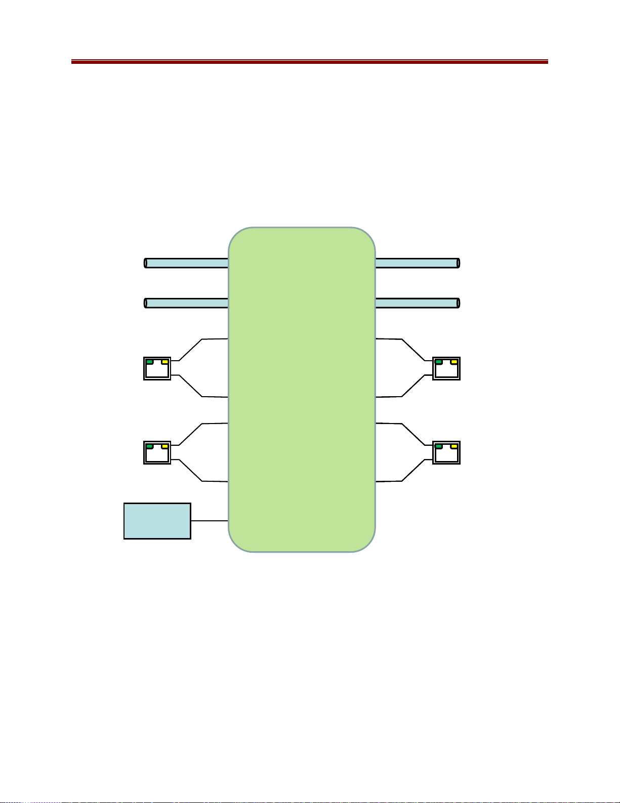
The 9220 is essentially a cross-connect switch where transport streams from inputs can be
connected to one or more outputs. A given input can be connected to as many as 8 outputs.
The following inputs are available:
• Up to 6 ASI inputs (shared with ASI outputs)
• Up to 8 IP inputs per Ethernet port (for a maximum of 16 IP inputs)
• One internal test packet generator (which can be used to generate ASI or IP test streams)
The following outputs are available:
• Up to 6 ASI outputs (shared with ASI inputs)
• Up to 8 IP outputs per Ethernet port (for a maximum of 16 IP outputs)
In general terms, configuring the 9220 is a two-step process:
Step 1: Configure the input.
Step 2: Configure the output. As part of this step, a connection between the input and the output
can be established.
7 9220-UM V1.1
Page 8
If you are making one-to-many connections, step 1 is performed once, and step 2 is performed
multiple times. It is also possible to configure the output first (without making the connection to
an input), configure the input next, and finally make the connection between the input and the
output.
Note that while it is possible to connect one given input to multiple outputs, only one connection
is allowed for a given output.
The overall architecture is depicted below.
Outputs
Inputs
Inputs
ASI
ASI
Up to 6
Up to 6
••• •••
••• •••
••• ••••••
Up to 6
Up to 6
•••••••••
•••••••••
Up to 6
Outputs
ASI
ASI
ASI
ETH1
ETH1
ETH2
ETH2
Test
Test
Test
Test
Generator
Generator
Generator
Generator
Up to 8
Up to 8
Up to 8
Up to 8
Cross-Connect
Cross-Connect
Switch
Switch
Up to 8
Up to 8
Up to 8
•••
•••
••••••
Up to 8
Up to 8
Up to 8
ETH1
ETH1
ETH1
ETH2
ETH2
ETH2
For the remainder of this manual, we will use the term port for a physical input/output port (such
as ASI or Ethernet), and stream for a transport stream present in the port. ASI ports support only
one stream, while Ethernet ports support multiple streams.
Redundancy Options
The 9220 can be configured to support transport stream redundancy. This means that the unit
can be configured with a “primary transport” and a “backup transport”. If the primary transport
disappears, the unit may be set to automatically switch to the backup transport, after a
configurable timeout. The following features are common to all redundancy modes:
8 9220-UM V1.1
Page 9

• Transport stream redundancy can be set to “Manual” or “Automatic”. In “Automatic”
mode, the unit will switch to the backup stream after a configurable timeout, if the
primary stream disappears. In “Manual” mode, the switch has to be performed by the
operator.
• Regardless of the Automatic/Manual mode, the operator always has the ability to instruct
the unit to switch to the other transport stream.
The 9220 offers two independent redundancy levels, which can be combined if desired:
• IP Input Address/Port Redundancy
• Connection Redundancy
IP Input Address/Port Redundancy
An IP Input receives a transport stream over UDP/IP, on a given IP Address/UDP Port
combination, with an optional Source IP address specification. For each IP Input, the unit allows
an optional backup IP Address/UDP Port/Optional Source IP Address combination to be
specified. If the transport stream disappears from the primary address/port combination, the port
can switch to the backup address/port combination (if configured for automatic redundancy).
The automatic switch timeout can be set to a value between 2 and 45 seconds.
This level of redundancy is available for all IP input ports, and is independent of any connections
that may exist to the port. It uses no internal resources in the 9220 (i.e., it does not “count” as an
input or as a connection), but it has the following limitations:
• It is only available for IP input ports.
• The primary and backup transport streams must be available on the same Ethernet port.
• The 9220 does not monitor the inactive stream. Therefore, if the active stream disappears
and the other stream not running either, the 9220 will be switching back and forth until
one of the two streams comes back.
The Connection Redundancy level does not have the above limitations, but it does use internal
resources in the 9220.
Connection Redundancy
In normal operation, an output port is connected to an input port. The 9220 offers the option of
having a backup input port for each connection. If the transport stream coming from the primary
input disappears, the connection can switch to the backup input if configured for automatic
redundancy. The automatic switch timeout can be set to a value between 2 and 45 seconds.
Connection redundancy does use resources – two input ports must be created and available, and
two connections are used (counting against the 8-connection maximum per input). This mode of
operation offers the following features:
• Different port types can be used as primary/backup pairs. For example, an ASI input can
be configured as the backup for an IP input or vice-versa. Here are some examples of
configurations that can exploit this flexibility:
9 9220-UM V1.1
Page 10

o An ASI input can be the backup for an IP Input. For example, the IP input can be
the primary feed, and the ASI input a local feed that will be switched in if the
primary remote feed disappears.
o ASI protection switching: two ASI inputs can be configured as primary/backup
feeds for an ASI output. If the primary ASI input disappears, the 9220 will
connect the ASI output to the backup ASI input.
o Primary/backup IP streams on separate networks: an IP input in ETH1 can be
configured as the primary, and another IP input in ETH2 can be configured as
backup.
• The unit continuously monitors both the primary and the backup transport streams. It
will only switch to the backup if it is active. In the situation where both streams are
inactive, and one of them starts flowing again, Connection Redundancy will recover
faster than Address/Port Redundancy.
• A given input may be used as a primary or backup input for multiple output ports (up to 8
ports).
Note that the two redundancy levels can be combined. It is possible to have a primary and a
backup IP input port for some output port, and each of these two IP inputs may be configured for
Address/Port Redundancy.
10 9220-UM V1.1
Page 11

Indicators and Switches
The 9220 card can be installed in the 10-slot 8310 frame, or in the 20-slot 8321 frame. Prior to
installing the card, first install the corresponding rear I/O module. Note that the rear I/O module
for the 8321 frame is different from the module for the 8310 (8310 frame requires an RM-9220B rear I/O module; 8321 frame requires an RM20-9220-B rear I/O module).
Rear I/O Module Indicators
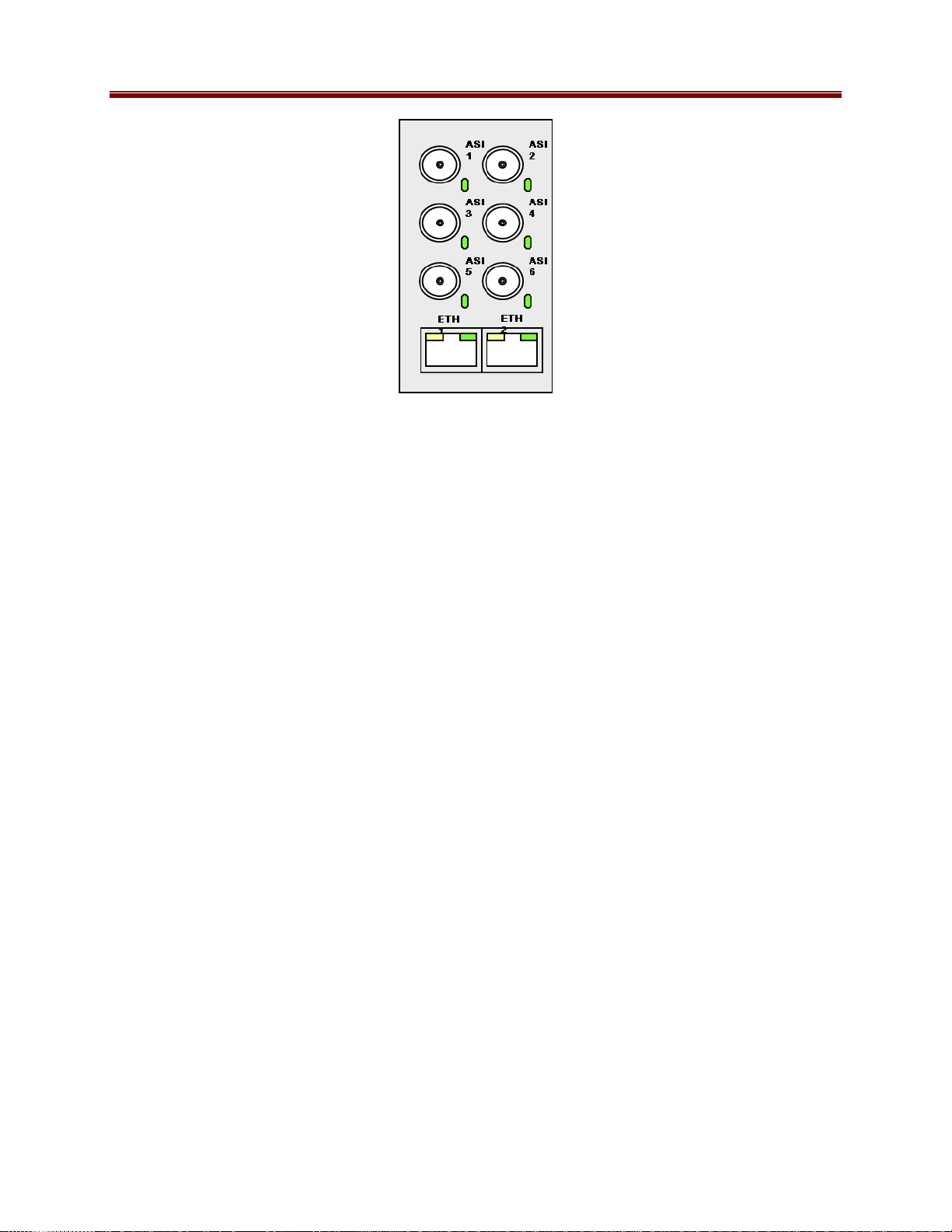
The 9220 rear I/O module is depicted below. It includes 6 ASI ports (configurable as inputs or
outputs) on standard BNC connectors, and two 100/1000 Mb/s Ethernet ports on standard RJ-45
connectors.
Each of the ASI ports has a green indicator LED, with the following states:
• LED off: ASI port is disabled.
• LED flashing once every 3 seconds: ASI port is configured as input, but it is not locked
to a signal (i.e., there is no input signal).
• LED flashing once per second: ASI port is configured as input, and is locked to a
signal.
• LED flashing multiple times per second: ASI port is configured as output.
Each of the Gigabit Ethernet ports has two indicator LEDs, with the following states:
• Green LED:
o Off: No link
o On: Link
• Yellow LED:
o Off: No activity (transmit and/or receive)
o Flashing: Port is currently transmitting and/or receiving
11 9220-UM V1.1
Page 12
Front Indicators
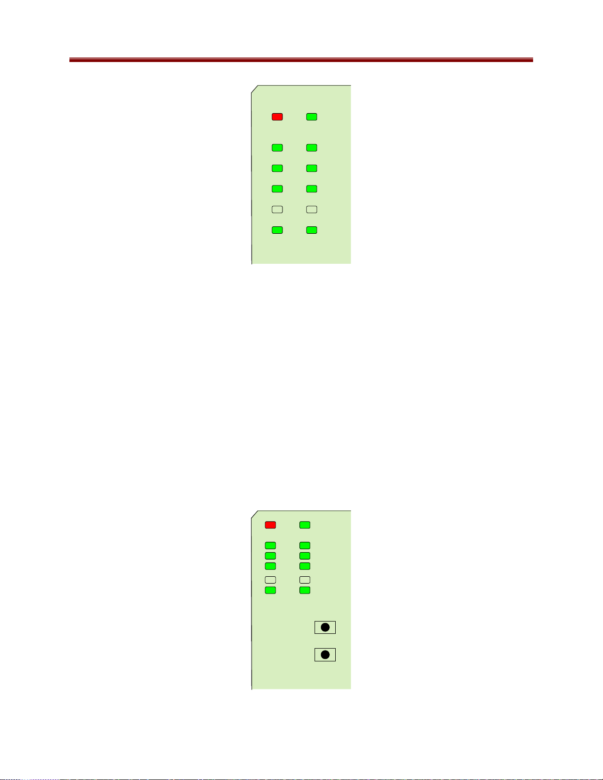
A similar set of indicators exist in the front of the board. These are visible when the frame front
door is opened. The indicator layout is depicted below.
The LED indicators are as follows:
• Status LED: indicates the overall status of the board.
o Green: no active alarm
o Red: at least one critical alarm present
When inserting a board in the frame, this LED will be red until the board starts operation.
At that point, it will turn green if there is no active alarm or red if there is at least one
alarm.
• Power OK LED: indicates that the power received from the frame is OK.
o Green: power OK
o Off: no power (or insufficient voltage – check the frame power status)
• AS1 1 through ASI 6 LEDs: these behave exactly the same as the corresponding rear
I/O module indicators.
• ETH1 and ETH2 LEDs: these indicate the status of the corresponding Ethernet
connection.
o Off: no link
o On: link OK, no activity
o Blinking: link OK, port is transmitting and/or receiving packets
12 9220-UM V1.1
Page 13
Top Corner
Top Corner
Status Power OK
Status Power OK
ASI 1
ASI 2
ASI 2
ASI 4
ASI 4
ASI 6
ASI 6
ETH 2 ETH 1
ETH 2 ETH 1
ASI 1
ASI 3
ASI 3
ASI 5
ASI 5
The board has other LEDs that may or may not be illuminated. They are intended for
engineering debug only.
Front Switches
The board has two pushbutton-type switches in the front, just below the LEDs, as depicted
below. Their operation is as follows:
• Default IP Switch: This switch is used to recover the board in the unlikely case of a
corrupted or broken firmware update. In most cases, the 9220 will detect the error and
automatically fall back into the factory-default firmware load. If it does not, pull the card
out, press and hold this switch, and push the card back into the frame while still holding
the switch. You can release the switch once the Status LED turns orange. This action
causes the card to revert to the factory-default firmware.
• Reset Switch: Pressing this pushbutton switch causes the card to reset.
Top Corner
Top Corner
Default IP
Default IP
Reset
Reset
13 9220-UM V1.1
Page 14

Operation and Management
The 9220 is configured using the free Dashboard™ application, which is available for Windows,
Apple OS X, and Linux. Dashboard can be downloaded from this link:
http://www.opengear.tv/n/?p=94
As with any openGear™ card, the card display is divided into a statistics panel on the left, and a
configuration panel on the right. Each panel has multiple tabs, corresponding to the various
functions in the card. Note that the Card State alarm indicator is also reflected in the green/red
Status LED in the front of the board. The Status LED will be green when Card State is green or
yellow, and will be red when Card State is red.
The following tabs are available:
• Product: this tab provides general information on the card, including firmware version,
uptime, temperatures, and other parameters. It appears only on the Statistics panel.
• Network: this tab is used to configure the IP addresses and network information for the
Ethernet ports. The statistics side of the panel includes some additional information such
as link state.
• ASI Ports: this tab is used to configure/monitor the ASI ports.
• IP Inputs: this tab is used to configure/monitor the IP Input ports. The configuration
panel provides the facilities to create, manage and delete ports; the statistics panel
includes reception status information.
• IP Outputs: this tab is used to configure/monitor the IP Output ports. The configuration
panel provides the facilities to create, manage and delete ports; the statistics panel
includes transmission status information.
• Connections: this tab is used to configure/monitor connections. The configuration panel
provides facilities to create, edit and delete connections; the statistics panel provides a
table where the status of all the connections in the unit can be inspected at a glance.
• Redundancy: this tab is used to manage and monitor the redundancy function. Manual
redundancy switches are initiated from the configuration panel.
• Admin: this tab is used for general administrative functions, such as firmware upgrades,
licensing, logs, and configuration management. The Test Packet Generator configuration
is also found under this tab.
14 9220-UM V1.1
Page 15

Product Tab
The Product Tab contains basic information about the 9220.
The following information is available:
• Build Date: Date the firmware image was built.
• Software revision: This indicates the firmware revision currently running. The format is
Major Version • Minor Version • Build Number.
• Serial Number: This is the serial number of this particular 9220 card.
• Rear Module: This indicates the status of the Rear I/O Module. It can have one of the
following states:
o
OK: The Rear Module is the correct module for the 9220.
o Not Installed: The 9220 is not connected to a rear module. The card is
operating normally, but it will not be useful as there are no input and output
connections to it.
o Wrong Module: The 9220 is connected to a rear module that was not designed
for it (most likely from another openGear™ vendor). Depending on the signals
present on that module, there may be a small chance of damage to the 9220;
Cobalt Digital Inc. recommends that this situation be rectified immediately. This
alarm will cause the front status LED to turn red.
• Card Uptime: Indicates how long the card has been running since it was last rebooted.
• Ambient Temperature: Temperature, in degrees centigrade, of the air intake of the card
(measured at the front edge of the card).
• Internal Temperature: Temperature, in degrees centigrade, at the back of the card.
• MDP Core Temperature: Temperature, in degrees centigrade, of the core MediaStorm
processing element.
The openGear™ frame is designed to operate in environments with up to 40
typically a 5
measured by the 9220. If that measurement is at 45
o
C temperature raise from the external ambient to the “Ambient Temperature”
o
C or higher, action must be taken to cool
down the ambient temperature.
15 9220-UM V1.1
o
C ambient. There is
Page 16
Network Tab
The Network Tab allows for configuration/monitoring of the two Ethernet ports.
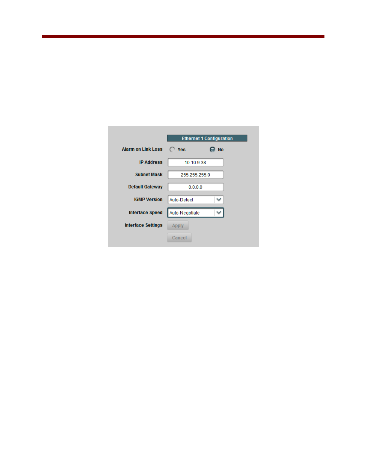
Network Configuration Tab
The Network Configuration Tab is used to set the individual parameters for each of the Ethernet
ports.
The following parameters can be configured:
• Alarm on Link Loss: If set to Yes, the card will raise an alarm if this Ethernet interface
looses link. The Card State indicator in Dashboard™ and the front Status LED will both
be red. If set to No, the card will still report loss of link in the Statistics page but no
alarm will be raised. It is recommended to turn on the alarm for ports that are in use;
only turn it off if you do not plan to connect that port to a network.
• IP Address: Enter the desired IP address for this Ethernet port.
• Subnet Mask: Enter the desired subnet mask for this Ethernet port.
• Default Gateway: Enter the desired default gateway for this Ethernet port, or 0.0.0.0 if
no gateway is available.
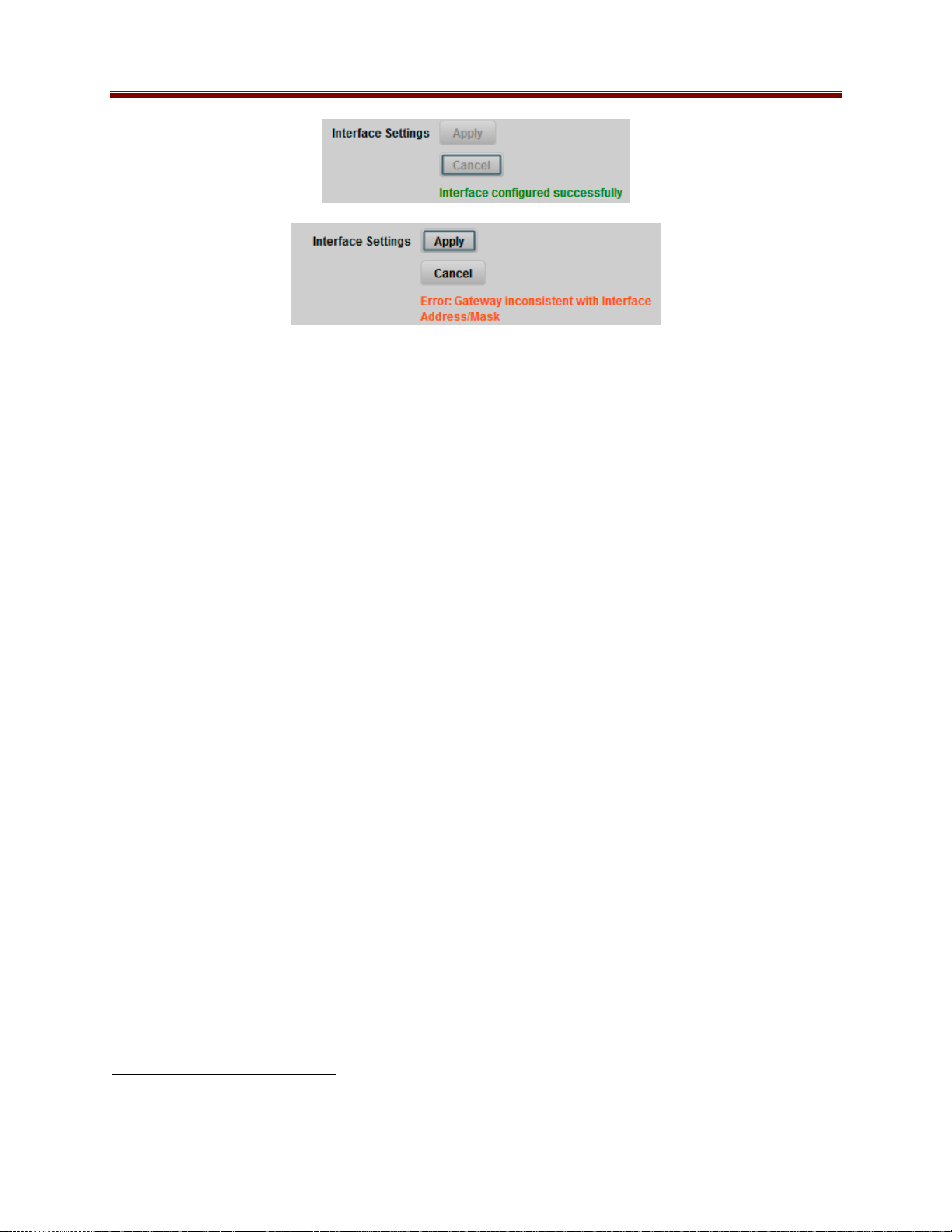
• Interface Settings: If you make any changes to the IP Address, Subnet Mask and/or
Default Gateway fields, the Apply and Cancel buttons become active. The changes only
take effect when you press the Apply button. Pressing the Cancel button reverts the
fields back to their original values. Note that the 9220 will check the consistency of the
data entered and will reject invalid combinations. Once the Apply button is pressed, a
status message appears just below the Cancel button, as follows:
16 9220-UM V1.1
Page 17
• IGMP Version: The 9220 implements the IGMP protocol for multicast reception. This
parameter controls the version of the protocol to be used.
o Auto-Detect: The 9220 will attempt to auto-detect the IGMP version in use by
inspecting the Group Membership Requests received from the router. It defaults
to IGMP Version 3 if no messages are received.
o IGMP Version 1: Force the use of Version 1 only (not recommended)
o IGMP Version 2: Force the use of Version 2 only
o IGMP Version 3: Force the use of Version 3 only
• Interface speed: Configures the speed of the interface. The 9220 Ethernet interfaces
only support two modes: 100 Mb/s Full-Duplex and 1 Gb/s Full-Duplex1.
o Auto-Negotiate: The Ethernet port will auto-negotiate the speed.
o 100 Mb/s Full-Duplex: Force the port to 100Mb/s Full-Duplex mode. Note that
the port will still perform auto-negotiation, but it will only advertise this mode.
o 1Gb/s Full-Duplex: restrict the operation to 1Gb/s Full-Duplex mode. Note that
the port will still perform auto-negotiation, but it will only advertise this mode.
Network Statistics Tab
The Network Statistics Tab reports the current IP configuration of each Ethernet port, as well as
their link state and running status.
1
Support for 10 Mb/s and Half-Duplex modes has been disabled, as these are unsuitable for MPEG transport over IP
applications. Moreover, any modern switch supports at least 100 Mb/s Full-Duplex.
17 9220-UM V1.1
Page 18
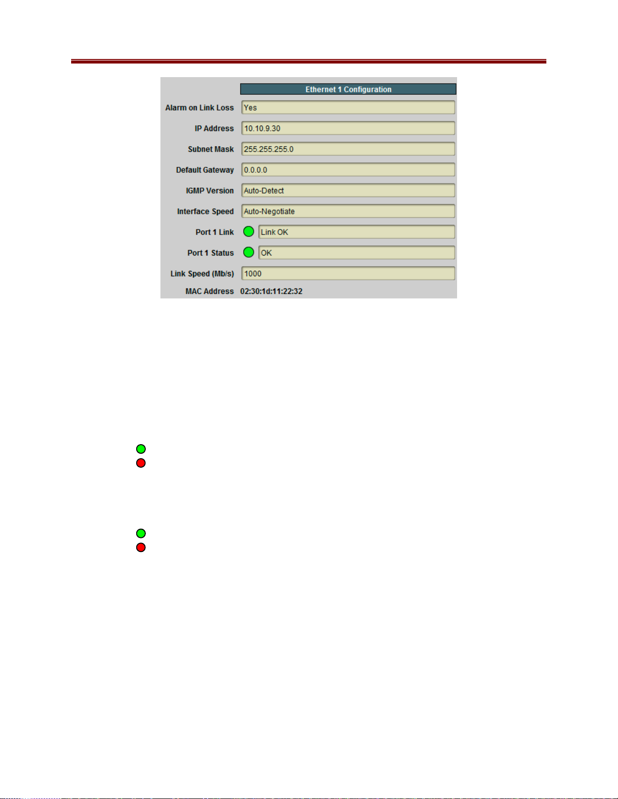
The following parameters are reported in the Network Statistics tab:
• Alarm on Link Loss: Reports the current setting of this parameter.
• IP Address: Reports the current IP Address for the port.
• Subnet Mask: Reports the current Subnet Mask for the port.
• Default Gateway: Reports the current Default Gateway for the port.
• IGMP Version: Reports the current setting for this parameter.
• Interface Speed: Reports the current setting for this parameter.
• Port 1/2 Link: This indicator has the following states:
o Link OK: The port has established link with the switch.
o No Link: The port does not currently have link. If Alarm on Link Loss is set to
Yes, the Dashboard™ Card State will be red and the Status LED in the front of the
board will also be red. If Alarm on Link Loss is set to No, this indicator will still be
red, but the alarm will not propagate.
• Port 1/2 Status: This indicator is the port overrun status. It has the following states:
OK: The port is operating normally.
o
o
TX Overflow: In the current configuration, the IP outputs are attempting to
transmit more than the port capacity (i.e., the overall output data for this port
exceeds the interface speed of 100 Mb/s or 1 Gb/s). The Dashboard™ Card State
will be red and the Status LED in the front of the board will also be red. In this
case, reduce the output bit rate (either by externally controlling the inputs or by
removing output ports). If this indicator is red, data is being dropped.
• Link Speed (Mb/s): This parameter reports the actual speed negotiated with the switch
for the port. If the port has no link, the value reported here is zero.
• MAC Address: This reports the MAC address of the Ethernet port.
18 9220-UM V1.1
Page 19
ASI Ports
The 9220 card has 6 ASI ports that can be individually configured as inputs or outputs. Unused
ASI ports can be disabled. This tab is used to configure and manage the ASI Ports.
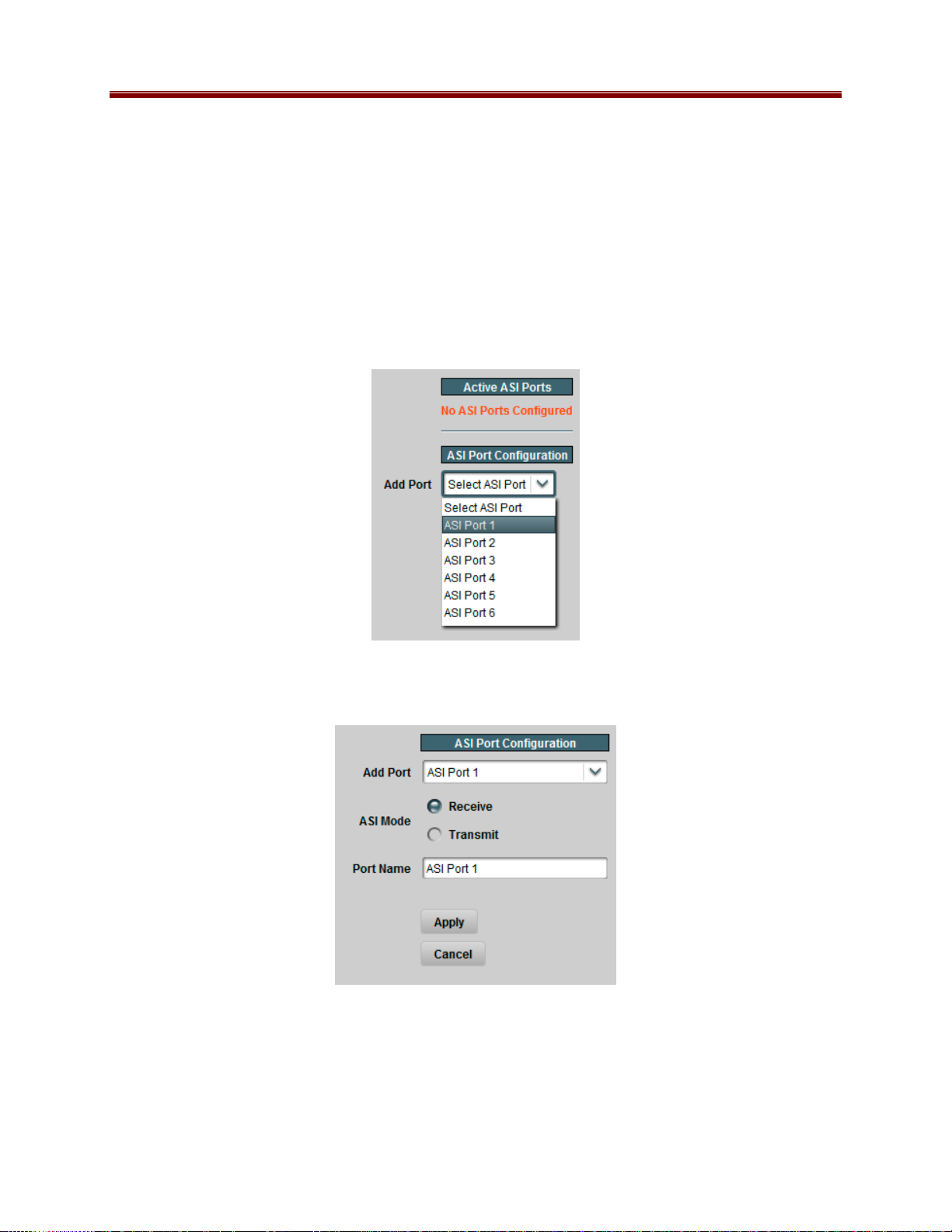
ASI Ports: Configuration Tab
If the 9220 has not yet been configured, all the ASI ports are disabled. The appearance of the
Configuration Tab is:
From the Add Port drop down list, select the port you wish to configure. The port configuration
defaults to Receive (ASI Input):
All 9220 inputs and outputs can be assigned a user-defined Port Name. This name is used to
identify the port later when making connections. Use any descriptive name suitable for your
application, or accept the default.
19 9220-UM V1.1
Page 20

If you are setting up an ASI input, there are no more parameters to configure. If you are
configuring an ASI output, select Transmit on the ASI Mode parameter; the ASI output
parameters become available, as depicted below:
ASI Output
ASI Output
Parameters
Parameters
Connection
Connection
Parameters
Parameters
The above configuration screen can be divided into two parts:
• ASI Output Parameters
• Connection Parameters
The Connection Parameters are common to all outputs, and are described in the Connections
section, later in this document. The ASI Output Parameters are:
• Packet Size: Select between 188 and 204 bytes.
• ASI Rate: The following two modes are available:
o Manual: In this mode, the ASI output bit rate is set to the value entered in the Bit
Rate field. The ASI output will maintain this rate at all times, as follows:
If there is no connection to the ASI port, or if the input connected to the
ASI port is not active, the ASI port will transmit NULL packets.
If the connected input bit rate is lower than the rate entered in the Bit Rate
field, the ASI port will add NULL packets as required to pad it to the
desired value. PCR packets will be re-stamped as required.
20 9220-UM V1.1
Page 21

If the connected input bit rate is higher than the rate entered in the Bit
Rate field, the ASI port will attempt to remove NULL packets from the
input in order to achieve the desired value. PCR packets will be
re-stamped as required. If there are not enough NULL packets to be
deleted, packets will be dropped, and an alarm will be raised. This alarm
will be indicated in the Dashboard™ Card State field, in the front Status
LED, and in the ASI Statistics page.
o Automatic: If this mode is selected, the Bit Rate field disappears. The ASI
output will exactly match the rate of the connected input. However, if the
connected input has no data, or if the ASI port is not connected to any input, there
will be no output, and any connected downstream ASI device will indicate loss of
sync. The ASI Statistics page will indicate this state. Note that an alarm will only
be raised if there is an input connected to the ASI output.
• Bit Rate: This field is only available if the ASI Rate mode is set to Manual. Enter the
desired ASI output bit rate here, in bits/second. The minimum value is 64,000 and the
maximum value is 213,000,000.
Once the port is configured, click on the Apply button, and the configuration takes effect. If
there are any errors, they will be reported in the area on top of the Apply button. Two types of
errors can be reported:
1. Errors related to the port configuration itself. The only error of this kind applies to ASI
outputs; the 9220 requires individual output transport stream licenses, and if none are
available, the port configuration will fail. Contact Cobalt Digital Inc. to obtain additional
licenses.
2. Errors related to the connection, if you are configuring one. These are described in the
Connections section.
As ports are configured, they become visible in the Active ASI Ports table. An example is
depicted below:
The columns of the table are as follows:
• Mode: Indicates the port mode (Transmit or Receive).
• Status: Indicates the port status. It can contain the following values:
21 9220-UM V1.1
Page 22

o OK: Port is operating normally. This status is issued for Transmit (Output) ports
only.
o Unlocked: Port is unlocked. If it is a Receive (Input) port, it means that it cannot
lock to the signal. If it is a Transmit (Output) port, it means that the port is in
Automatic mode and it has no input.
o Locked: Receive (Input) port is locked to a signal.
o Overflow: Transmit (Output) port overflow. This means that the ASI Output is in
Manual mode, and the configured bit rate is insufficient to carry the input
connected to it. This situation will raise an alarm.
• Size: Indicates the transport packet size, in bytes. For ASI Outputs, this is the configured
size. ASI Inputs auto-detect the packet size and report it here. If the port is not locked to
a signal, it will report zero here (see ASI Port 2 in the figure above).
• TS Bit Rate (b/s): This reports the transport stream bit rate, in bits/second. For ASI
Outputs, this is the actual rate in the ASI port. For ASI Inputs, this is the bit rate after
conversion to 188-byte packets. For ASI Outputs in Manual mode, the rate reported here
is the configured rate; for ASI Inputs and ASI Outputs in Automatic mode, this is the
measured bit rate over 2-second windows, and may fluctuate by ±750 b/s.
• Port Name: This reports the configured Port Name.
• Edit Button: Clicking on this button allows reconfiguration of the port. The ASI Port
Configuration screen re-appears, with the settings for the selected port.
• Delete Button: Clicking on this button deletes the port. The ASI port is disabled, and the
entry in the table is removed. Any connections to or from the port are removed.
ASI Ports: Statistics Tab
The Statistics Tab for the ASI Ports provides a quick visual summary status for the ports. A
sample, corresponding to the table example of the previous section, is depicted below.
Each of the ASI Port indicators can have the following values:
• TX OK: The port is operating normally in transmit mode (ASI Output).
• RX Locked: The port is operating normally in receive mode (ASI Input); it is locked
to an input signal.
22 9220-UM V1.1
Page 23

• Disabled: The port is disabled. There will be no entry in the Active ASI Ports table
for it.
• TX Overflow: The port is in transmit mode, manual bit rate setting, and the connected
bit rate is excessive. The Dashboard™ Card State will be red and the Status LED in the
front of the board will also be red. To correct this problem, either externally reduce the
input bit rate, or increase the ASI output bit rate, or configure the port in Automatic
mode. If this alarm is active, data is being dropped.
• TX Unlocked: The port is in transmit mode, automatic bit rate, and there is no data
rate coming to it. Any downstream ASI receivers will loose lock. Dashboard™ Card
State and the Status LED will be red if there is a connection to this port.
• RX Unlocked: The port is in receive mode, and it is not locked to any signal.
Dashboard™ Card State and the Status LED will be red if there is a connection to this
port.
23 9220-UM V1.1
Page 24

IP Inputs
IP Inputs receive transport streams over UDP/IP from the Ethernet ports, de-jitter them, and
make them available for connections to outputs. The 9220 card supports up to 8 transport stream
inputs per Ethernet port. IP Inputs have the following specifications:
• Format support: MPEG-2 Transport Packets over UDP/IP.
• Maximum data rate per stream: 120 Mb/s.
• Number of MPEG-2 Transport Packets per UDP datagram: between 1 and 7 (no support
for IP fragmentation).
• Addressing support: unicast, multicast and broadcast.
• Configurable source IP address filtering.
• Configurable IP Address/UDP Port redundancy.
IP Inputs: Configuration Tab
The IP Input Configuration follows a similar workflow as the ASI Ports. Ports can be created,
configured, and deleted. Before any ports are created, the Configuration Tab appears as depicted
below:
To create an IP Input stream, first select the desired Ethernet port in the Add Stream drop-down
box. Once that selection is made, the IP Input Stream Configuration is displayed, as depicted
below. The configuration screen has three areas:
• Common Parameters: apply to the stream input as a whole, regardless of the
redundancy options.
• Redundancy Control: allows selection of the redundancy mode.
• Addressing Parameters: allow selection of the network stream to be received
24 9220-UM V1.1
Page 25

Common
Common
Parameters
Parameters
Redundancy
Redundancy
Control
Control
Primary
Primary
Addressing
Addressing
Parameters
Parameters
Common Parameters
• Enabled: This allows the stream to be enabled or disabled. If it is disabled, no packet
reception takes place. This feature is provided for testing purposes (i.e., temporarily
disable an input for fault-finding). Most users will leave the stream enabled.
• Stream Name: All 9220 inputs and outputs can be assigned a user-defined name. This
name is used to identify the port later when making connections. Use any descriptive
name suitable for your application, or accept the default.
• Latency (ms): This is the de-jitter latency, in milliseconds. This setting corresponds to
the buffering latency introduced by the 9220 to remove IP jitter. At 120 Mb/s, the
maximum latency supported is 100 ms; at lower rates, the maximum will be
proportionally increased (for example, at 20 Mb/s, the maximum is 600 ms). Entering a
value of 0 (zero) disables the de-jitter function2. Once the port is created an in operation,
the 9220 will measure the actual jitter. Therefore, if the input jitter is unknown (which is
the most common case), set this parameter to 100 ms, run the unit for a representative
period of time, read the measured jitter, and then reduce it. This process is described in
detail later in the “Determining the Latency Settings” section.
2
Note that an IP stream with a de-jitter setting of zero must not be connected to an ASI output as it will cause
overflows.
25 9220-UM V1.1
Page 26

Redundancy Control
As described in the Redundancy Options section, the IP Inputs offer option of defining a primary
and a backup address/port combination. This is enabled in by the Backup parameter, which
offers the following options:
• Disabled: no redundancy.
• Automatic: a redundant address/port can be defined, and the input will automatically
switch between primary and backup if the stream disappears. If this option is selected, a
new field is displayed, where the Switch Time can be configured; valid values are
between 2 and 45 seconds:
• Manual: a redundant address/port can be defined, but the input will not automatically
switch – that will have to be done manually by the operator. Redundancy switches are
performed in the Redundancy Tab, described later in the Redundancy section.
Addressing Parameters
The Addressing parameters allow the definition of one or two address/port combinations for
reception. If Backup is set to Disabled, only the primary settings are displayed; otherwise, both
the primary and backup settings are displayed, as shown below.
26 9220-UM V1.1
Page 27

The Primary/Backup addressing parameters are configured as follows:
• UDP Port : selects the UDP port to receive from. Valid values are between 1 and 65535.
Note that, in traditional IP networks, UDP ports between 1 and 1023 are reserved for
administrative uses. It is recommended to use UDP ports 1024 and higher. The 9220,
however, will accept any legal value.
• Reception: selects the address to receive from. The options are:
o Unicast: the packets are being sent to the IP address of this Ethernet port. The
address of the Ethernet port can be set or reviewed in the Network Tab.
o Multicast: the packets are being sent to a Class-D multicast address (between
224.0.0.0 and 239.255.255.255). If this option is selected, a new field is
displayed to accept the multicast address:
The 9220 will warn the user if the address entered in this field is not a multicast
address. The device includes a full implementation of IGMP V1/V2/V3 to
convey group membership information to upstream routers; IGMP is configured
in the Network Tab.
o Broadcast: the packets are being sent to a broadcast address (either the all-hosts
broadcast address of 255.255.255.255 or a subnet broadcast address). Note that
this is extremely rare in practice.
• Source: If desired, the 9220 can filter packets by source IP address. This is useful when
the network includes a primary and a backup stream, sent to the same address, but from
different sources. The options are:
o Any Address: this input will accept packets from any address.
o Specific Address: this input will only accept packets from a given specific
address. When this option is selected, a new field appears where the desired
source IP address can be entered:
Unicast/Broadcast MulticastUnicast/Broadcast Multicast
The Source Address must be a valid unicast address. In case of Multicast
reception, the 9220 will go into SSM (Source-Specific Multicast) mode. If IGMP
V3 is in use, the card will use it to inform the network of the choice selection.
Note that the 9220 does not require an IGMP V3 network to operate in SSM
mode, as it can filter packets in real-time at line rate.
27 9220-UM V1.1
Page 28

Once the configuration information is filled in, click on the Apply button to make it active. If
there are no errors, the port will be created, and the configuration area disappears. If any errors
are detected, they will be displayed at the top of the Apply button. The following errors are
flagged:
• Error: enter a Source Address or select "Any Address": you selected Specific Address
for Source but left the Source Address field as 0.0.0.0.
• Error: X.X.X.X is NOT a multicast address: you selected multicast reception, and
entered an address that is not multicast. Multicast addresses go from 224.0.0.0 to
239.255.255.255.
• Error: X.X.X.X is NOT a valid unicast address: you entered an invalid unicast address.
Valid unicast addresses go from 0.0.0.1 to 223.255.255.255, with the exception of the
loopback range of 127.0.0.0 to 127.255.255.255.
• Error: Primary and Backup settings are the same: you entered the exact same
configuration settings for the primary and backup address/port. They must have at least
one difference.
• Error: Primary/Backup UDP Port/Address conflict with Port X/Y Primary/Backup: you
are attempting to configure an address/port combination that is already in use by another
input in the same Ethernet port. The 9220 is capable of internally replicating transport
streams; just use the other port again in the connection. There is, however, one special
case: if you want to configure an input with a given address/port combination and any
source, and another input with the same address/port combination and a specific source,
you must configure the input with specific source first.
• Error: Ethernet Port 2 not licensed: operation of the second Ethernet port requires a
license; please contact Cobalt Digital Inc.
• Maximum number of streams exceeded on this port: you will receive this message if
you attempt to create more than 8 IP inputs on a given Ethernet port.
Active IP Inputs Table
Once the input is created, it is added to the Active IP Inputs table, which has Basic and
Advanced views. This table provides a summary of the configuration and status of the input
stream. An example of this table, in the Basic view, is depicted below
28 9220-UM V1.1
Page 29

The Basic view includes the following:
• Enabled: The configured value of this parameter.
• Locked: This column will have Yes for inputs that are receiving a valid transport stream,
and No for inputs that are not.
• TS Bit Rate (b/s): This column provides the measured bit rate of the input transport
stream. This does not include UDP and IP overhead.
• UDP Port : The active reception UDP port (i.e., the UDP port currently being used by the
input).
• Reception Address: The active reception address (i.e., the address being currently used
by the input). If you selected Unicast, this field will contain the IP address of the
corresponding Ethernet interface. If you selected Multicast, this field will contain the
configured multicast address. If you selected Broadcast, this field will contain the word
“Broadcast”.
• Stream Name: The configured stream name.
• Edit Port: If you click on this button, you can modify all the parameters for this input.
The configuration area will re-open with the current input settings.
• Delete Port: If you click on this button, the port is deleted and removed from the table.
When the Advanced view is selected, additional fields appear in the table, as depicted below:
The Advanced view includes all items in the Basic view plus the following:
• Backup Mode: The configured value of this parameter.
• IP Packet Rate (pkts/s): The measured IP input packet rate, in packets/second. This
field is useful for debugging: if you have a non-zero IP Packet Rate, but a zero TS Bit
Rate, this indicates that the packets being received by the 9220 do not contain a valid
transport stream. This allows differentiation between a transport network problem (no
packets being received) and a data format problem (packets contain invalid data).
• Latency (ms): The configured value of this parameter.
• Max Jitter (ms): The maximum jitter measured by the 9220 for this input stream. This
is reported as zero if there is no reception.
• Source Address: The active source address (i.e., the address currently being used by the
input). This will have the word “Any” if the Source was configured as Any Source, or
the configured IP address.
29 9220-UM V1.1
Page 30

Additionally, when you select the Advanced view, a button to reset the Max Jitter measurement
becomes available. When pressed, it resets the measurement for all configured input streams.
Determining the Latency Settings
The data in the Advanced view is useful in determining the best Latency setting for the input
stream. The procedure is as follows:
1. Configure the desired input streams, using a high value for the latency setting –
100 milliseconds is a good starting point.
2. Make sure that your streams are operating as desired, and that your network is properly
set up.
3. Click on the “Reset Max Jitter Measurement” button in the Advanced view.
4. Let the system run for a period of time – a good choice would be 24 to 48 hours.
5. For each input, check the Max Jitter measurement in the Advanced view. For proper
operation, the Latency setting must be higher than the Max Jitter. We recommend adding
a 30% margin.
6. Reconfigure the latency value on each port to the optimum value. Note that changing the
latency setting causes a short stream interruption.
IP Inputs: Statistics Tab
The Statistics tab for the IP input ports contains a summary of each port status. There are two
sub-tabs: one for Ethernet 1, and another for Ethernet 2. The tab is depicted below:
Ethernet Port 1 Ethernet Port 2Ethernet Port 1 Ethernet Port 2
30 9220-UM V1.1
Page 31

The indicators can have the following values:
• OK: The IP Input is receiving a valid transport stream.
No Lock: The IP Input is not receiving a valid transport stream. If there is a
•
connection to this input, Dashboard™ Card State and the Status LED will be red.
•
Disabled: The IP Input has been disabled (by setting Enable to No).
31 9220-UM V1.1
Page 32

IP Outputs
IP Outputs receive data from connected inputs, format this data for transmission over UDP/IP,
and send it with very precise timing over the Ethernet ports. The 9220 card supports up to 8
transport stream outputs per Ethernet port. IP Outputs have the following specifications:
• Format support: MPEG-2 Transport Packets over UDP/IP.
• Number of MPEG-2 Transport Packets per UDP datagram: fixed at 7.
• Addressing support: unicast, multicast and broadcast.
• Advanced control over the IP header fields available.
IP Outputs: Configuration Tab
The IP Output Configuration follows a similar workflow as the IP Inputs. Ports can be created,
configured, and deleted. Before any ports are created, the Configuration Tab appears as depicted
below:
To create an IP Output stream, first select the desired Ethernet port in the Add Stream dropdown box. Once that selection is made, the IP Output Stream Configuration is displayed, as
depicted below (Basic View). The configuration screen has two areas:
• IP Output Parameters: these are the parameters specific to the IP Output configuration.
The set of parameters available for configuration depends on the View selection. In the
Basic view, suitable default values are entered for the advanced parameters.
• Connection Parameters: these allow a standalone or redundant connection to be made
to the output port.
The Connection Parameters are common to all output ports, and will be described in the
Connections section, later in this document.
32 9220-UM V1.1
Page 33

IP Output
IP Output
Parameters
Parameters
Connection
Connection
Parameters
Parameters
The Basic View configuration parameters are as follows:
• Enabled: This allows the output stream to be enabled or disabled. If it is disabled, no
packet transmission takes place. This feature is provided for testing purposes (i.e.,
temporarily disable an output for fault-finding). Most users will leave the stream
enabled.
• UDP Port : selects the UDP port to transmit to. Valid values are between 1 and 65535.
Note that, in traditional IP networks, UDP ports between 1 and 1023 are reserved for
administrative uses. It is recommended to use UDP ports 1024 and higher. The 9220,
however, will accept any legal value.
• Destination Address: selects the IP address to transmit to. Any unicast or multicast
address can be entered here, with the exception of the loopback range (127.0.0.0 to
127.255.255.255). The 9220 will also accept the broadcast IP address of
255.255.255.255, and will transmit the packets as Ethernet broadcasts. Use of
broadcasts, however, is strongly discouraged.
• Stream Name: All 9220 input and output ports can be assigned a user-defined name.
This name is used to identify the port later when making connections. Use any
descriptive name suitable for your application, or accept the default.
If the Advanced View is selected, four more parameters are available for configuration:
33 9220-UM V1.1
Page 34

Advanced
Parameters
• TOS: This parameter allows the configuration of the Type-Of-Service (TOS) byte in the
IP header (also known as the Differentiated Services – DS – field). Valid values are
between 0 and 255. Configuring this is only useful if the downstream router is
configured to honor the field.
• TTL: This parameter allows the configuration of the Time-To-Live (TTL) byte in the IP
header. Valid values are between 0 and 255. If not explicitly configured, it defaults to
128. This field controls how many hops the packet can traverse before it is dropped by a
router. The default value of 128 is suitable for virtually all applications.
• DF Bit: This parameter allows the configuration of the Do-not-Fragment (DF) bit in the
IP header. The 9220 will never produce fragmented packets, and with the UDP payload
set to 7 transport packets, the IP packets are guaranteed to fit inside the Ethernet MTU.
This control is provided for compatibility with legacy switches/routers. Some legacy
equipment may exhibit performance problems if this bit is not set. This is not an issue
with current network equipment.
• RTP: If this box is checked, the 9220 will include RTP (Real Time Protocol) headers in
the output flow. If it is not checked, the transport stream will be sent over UDP/IP
without any additional headers. Note that RTP requires the use of even UDP port
numbers.
Once the configuration information is filled in, click on the Apply button to make it active. If
there are no errors, the port will be created, and the configuration area disappears. If any errors
are detected, they will be displayed at the top of the Apply button. Two types of errors can be
reported:
34 9220-UM V1.1
Page 35

1. Errors related to the port configuration itself. These are listed below.
2. Errors related to the connection, if you are configuring one. These will be described in
the Connections section.
The following configuration-related errors are flagged:
• Error: UDP Port/Address conflict with Port X/Y: you have configured two IP Output
streams with the same destination IP Address and UDP port, on the same Ethernet
interface. Please review your settings.
• Error: No Output License Available: output transport streams are individually licensed
in the 9220. Contact Cobalt Digital Inc. to obtain additional licenses.
• Error: Ethernet Port 2 not licensed: operation of the second Ethernet port requires a
license; please contact Cobalt Digital Inc.
• Maximum number of streams exceeded on this port: you will receive this message if
you attempt to create more than 8 IP inputs on a given Ethernet port.
• Error: UDP Port must be even if RTP is enabled: if you check the RTP box in the
Advanced view, the UDP port number must be even. Either select an even number or
uncheck the RTP box.
If the configuration is successful, the output stream will be added to the Active IP Outputs table.
Active IP Outputs Table
Once the output is created, it is added to the Active IP Outputs table, which has Basic and
Advanced views. This table provides a summary of the configuration and status of the output
stream. An example of this table, in the Basic view, is depicted below
The Basic view includes the following:
• Enabled: The configured value of this parameter.
• TS Bit Rate (b/s): This column provides the current bit rate of the output transport
stream. This does not include UDP and IP overhead.
• UDP Port : The configured value of this parameter.
• Destination Address: The configured value of this parameter.
35 9220-UM V1.1
Page 36

• Stream Name: The configured stream name.
• Edit Port: If you click on this button, you can modify all the parameters for this output.
The configuration area will re-open with the current output settings.
• Delete Port: If you click on this button, the port is deleted and removed from the table.
When the Advanced view is selected, additional fields appear in the table, as depicted below:
The Advanced view includes all items in the Basic view plus the following:
• TOS: The configured value of this parameter.
• TTL: The configured value of this parameter.
• DF: The configured value of this parameter.
• RTP: The configured value of this parameter
• Destination MAC: The destination MAC address for this IP Output. For multicast
destination addresses, this is derived from the destination IP address using the rules from
RFC 1112. For unicast destination addresses, this is obtained using the ARP protocol. If
this entry is the word Unknown, the 9220 has failed to obtain a destination MAC
address. The port is not streaming. A more detailed description of the unicast MAC
address algorithms used in the 9220 is presented below.
Managing Unicast MAC Addresses
When the 9220 is configured with a unicast destination address, it needs to obtain a
corresponding MAC address (corresponding to either the final destination, if it is in the same
subnet, or to the default gateway). These MAC addresses are obtained using the ARP protocol.
The 9220 uses a custom MAC address management algorithm, designed specifically for MPEG
operation.
When an IP Output port with a unicast destination address is created, the 9220 immediately starts
attempting to obtain a MAC address for it, using standard ARP requests. These requests are
issued every two seconds until answered. No packets will be transmitted on that IP Output until
a MAC address can be obtained. Note that this process will happen even if the port is configured
to be in the disabled state.
36 9220-UM V1.1
Page 37

Once a MAC address is obtained, the 9220 will cache it for about 5 minutes, as it is usual for IP
devices. Unlike other IP devices, the 9220 will keep on using the MAC address until a response
is received, to avoid stream interruptions. If no response is received at that time, the 9220 will
raise a yellow alarm. This alarm can be seen in the IP Output Statistics tab, described in detail
below.
The current state of the 9220 current streaming ARP cache is available in the Advanced View of
the Active IP Outputs table, described above.
IP Outputs: Statistics Tab
The Statistics tab for the IP output ports contains a summary of each port status. There are two
sub-tabs: one for Ethernet 1, and another for Ethernet 2. The tab is depicted below:
Ethernet Port 1 Ethernet Port 2Ethernet Port 1 Ethernet Port 2Ethernet Port 1 Ethernet Port 2
The indicators can have the following values:
OK: The IP Output is operating normally (either streaming or ready to stream).
•
• No Response: The IP Output is configured for unicast operation, but it does not have a
destination MAC address. If there is a connection to this output, Dashboard™ Card State
and the Status LED will be red.
•
No Response: The IP Output is configured for unicast operation, and the destination
stopped responding to ARP. The IP Output is using an old cached MAC address. If
there is a connection to this output, the Dashboard™ Card State will be yellow (but
packets are being transmitted).
Disabled: The IP Output has been disabled (by setting Enable to No).
•
37 9220-UM V1.1
Page 38

Connections
The Connections allows the creation, deletion, and management of input-output connections.
The Statistics tab includes all connected input/output status indicators and an overall summary
status indicator, which allows the operator to immediately pinpoint errors.
Connections Configuration Tab
The Connections configuration tab is depicted below. The message “Connection Table Empty”
will be displayed if there are no configured input/output connections in the 9220. As indicated in
the figure, the Connections configuration area is divided into two parts: a source port selection,
and a destination port selection.
Source
Selection
Destination
Selection
To establish a connection, simply select a source (and optionally a backup source), a destination,
and then click on Apply.
Source Selection
The Source Selection area is available in the Connections tab, as well as in the ASI Ports and IP
Outputs tabs. This allows the operator to establish a connection to a given output as that output
is being configured. The operation is the same regardless of the location of the control.
The Source Port Selection is a two-step process:
38 9220-UM V1.1
Page 39

• Step 1: Select the port type in the Source Port drop-down list. The options are:
o IP Input 1: UDP/IP Input streams from Ethernet Port 1.
o IP Input 2: UDP/IP Input streams from Ethernet Port 2.
o ASI Input: ASI ports configured as inputs
o TPG: Test Packet Generator (internal test stream).
• Step 2: Select the individual stream in the Source Stream drop-down list. The names
presented here are the Stream Names configured when the ports were created. If no
streams were configured in that port, no options will be presented. This process is
illustrated below.
Default Names:
39 9220-UM V1.1
Page 40

Customized Names:
In some situations, it may be desirable to identify the IP streams by their address/port
combinations rather than using a name. This mode can be enabled by selecting Stream
Addresses in the Stream Display control, as depicted below. This operation does not affect the
user-defined names.
40 9220-UM V1.1
Page 41

If a backup connection is desired, it can be selected at this point as well. The same two options
are available: Automatic redundancy, where the 9220 will switch by itself after a configurable
timeout, and Manual redundancy, where the operator is responsible for switching. If Automatic
redundancy is selected, a field to configure the switch time becomes available. Valid values are
from 2 to 45 seconds. This is illustrated below.
If you select Automatic or Manual for the Backup Connection, a second set of Source
Port/Source Stream drop-down menus are displayed, to select the backup source. These operate
in exactly the same fashion as the primary source selections. The complete interface is shown
below.
Primary
Source
Backup
Source
Destination Selection
The Destination Selection operates in the same fashion as the Source Selection. It is again a twostep process, where a port is selected, and then a stream on that port is selected. Note that only
one connection can be made to any given output; therefore, the 9220 will only offer unconnected
outputs in the Destination Selection. If you wish to modify an existing route, either delete and
recreate it, or edit it. This process is explained later in this section.
The Destination Port Selection is depicted below. The options are as follows:
• IP Output 1: UDP/IP Output streams transmitted on Ethernet Port 1.
• IP Output 2: UDP/IP Output streams transmitted on Ethernet Port 2.
• ASI Output: ASI ports configured as outputs
41 9220-UM V1.1
Page 42
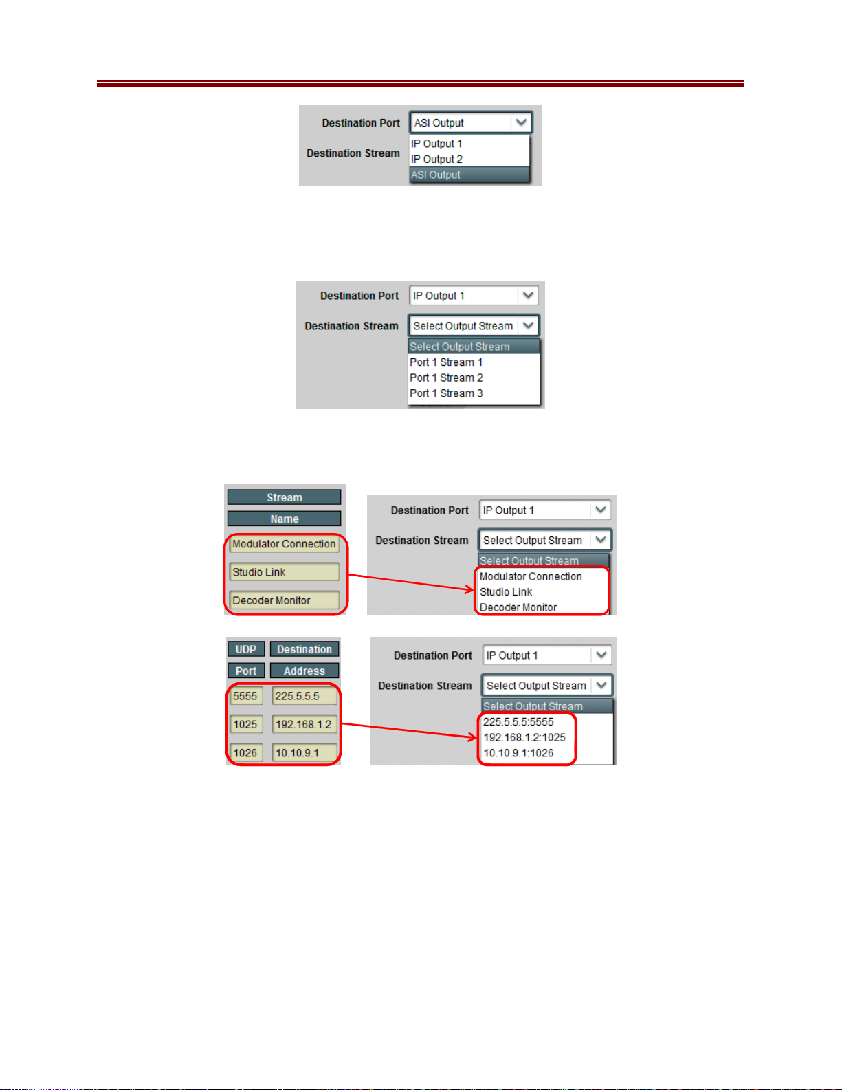
Once the port is selected, the Destination Stream drop down menu is populated with the
available output streams on that port. Only streams that are unconnected and enabled are
presented:
In the same fashion as with the Source Selection, the names can be customized, and the selection
can be presented as addresses rather than names. Both situations are illustrated below.
Establishing the Connection
Once the connection is configured, click on Apply to establish it. If no errors are detected, the
connection is established and added to the Current Connections Table. If the connection fails,
an error message will appear next to the Apply button. The following errors are detected:
• Error: Missing primary source selection: you have not selected a primary source for the
connection.
• Error: Missing destination selection: you have not selected a destination for the
connection.
42 9220-UM V1.1
Page 43

• Error: Missing backup source selection: you have selected Automatic or Manual
redundancy, but you did not select a backup source. Either select Disabled on Backup
Connection or select a backup source.
• Error: Primary and backup selections are the same: you have selected Automatic or
Manual redundancy, and you selected the same source for both primary and backup.
Either select Disabled on Backup Connection or select different source for either
primary or backup.
• Error: Maximum number of connections exceeded for primary/backup: the 9220 can
support only a maximum of 8 connections to any given input. This was exceeded for
either the primary or backup.
The Current Connections Table
As connections are established (either in the Connections tab, or as part of the output port
configuration), they are added to the Current Connections table. Regardless of how they got
added, the connections can be edited or deleted using the functions in this table. A sample of this
table is depicted below.
The following columns are available in this table:
• Source Port, Source Stream: these columns have the current source for the connection.
If there is a redundancy switch, these fields will change accordingly. The Source Stream
column will change to indicate address/port if Stream Display is set to Stream
Addresses.
• Backup Mode: this column contains the configured value for this parameter.
• Destination Port, Destination Stream: this column contains the destination for the
connection. The Destination Stream column will change to indicate address/port if
Stream Display is set to Stream Addresses.
• Edit: if you click on this button, you can edit the connection. The selection area below
the table will be populated with the connection parameters.
• Delete: if you click on this button, the corresponding connection will be deleted.
• Select/Delete Selected Connections: if you need to delete multiple connections, mark
them in the Select column, and then click the Delete Selected Connections button.
43 9220-UM V1.1
Page 44

Connection Statistics Tab
The Connection Statistics Tab presents the combined status of all the established connections, in
one table. It includes the Source Port, Source Stream, Destination Port and Destination Stream
fields to identify the connections, and the rows are in the same order as the table in the
Configuration Tab. The Statistics tab contains two additional fields, the Source Status and the
Destination Status. Since these are color-coded, it is simple to quickly identify any problems.
The Statistics Tab also includes an overall Connection Status indicator, which contains the
highest priority alarm in the table. If the Connection Status indicator is red, the Dashboard™
Card State will be red as well, and the Status LED in the front of the card will also be red. If the
Connection Status indicator is yellow, the Dashboard™ Card Status may also be yellow (unless
there is a higher priority alarm elsewhere).
The meaning of the indicators is as follows:
• OK: The stream is operating normally. If it is an input, it means that a transport
stream is being received by it; if it is an output, it means that it is either transmitting or
ready to transmit.
• Warning: The stream is configured but disabled. Simply enabling the stream may
clear this situation.
• Error: The stream is configured but has detected a problem. If it is an input, this
normally means that no data is being received (e.g., an IP input is not seeing any packets,
an ASI input is not locked). If this is an output, it normally means that the output is
either unable to send (e.g., an IP output configured for unicast but unable to find the
destination MAC address) or dropping packets (e.g., an oversubscribed ASI output). ASI
Outputs with Automatic Rate will be in this state if they do not have data to transmit.
A sample of the Connection Statistics Tab is depicted below.
44 9220-UM V1.1
Page 45

Redundancy
The Redundancy Tab provides a unified view of all configured primary/backup pairs, for both
Address/Port Redundancy and Connection Redundancy. The following features are available on
this tab:
• Display of all primary/backup parameters.
• For each primary/backup pair, indication of which setting is online (active).
• Ability to manually switch the redundancy.
The Configuration and Statistics Redundancy Tabs are depicted below. Note that Address/Port
Redundancy and Connection Redundancy have their own individual tabs, both in the Statistics
and in the Configuration areas.
As redundant address/port and connection pairs are configured, they automatically appear in the
tabs above.
Address/Port Redundancy
A populated Address/Port Redundancy table is depicted below. The only difference between the
Configuration and Statistics area is that the former includes a Switch button; otherwise they are
the same.
45 9220-UM V1.1
Page 46

Confi gurat ion Tab
Stat isti cs Tab
The fields in the table are:
• Primary/Backup Port: Configured UDP port for primary/backup.
• Primary/Backup Address: Configured reception IP address for primary/backup.
• Primary/Backup Source: Configured source IP address for primary/backup. If the
setting is to receive from any source, this field will contain the word Any.
• Primary/Backup State: This indicates which setting is online (active) and which setting
is offline. The indicator has the following possible values:
: This indicates that the setting is online (active).
: This indicates that the setting is offline (inactive).
• Switch Time (sec): This indicates the automatic redundancy switch time, in seconds. If
manual redundancy is configured, the value displayed here is 0 (zero). In the example
above, Port 1/1 is in automatic redundancy with a switch time of 5 seconds, while
Port 1/2 is in manual redundancy.
• Manual Redundancy Switch: This control is in the configuration tab only. If you click
on this button, a manual redundancy switch is initiated. The button is available for both
manual and automatic redundancy modes. Note that, if the port is in automatic
redundancy mode, and you manually switch it to a stream that is not running, it will
switch back to the running stream after the configured switch time.
Connection Redundancy
A populated Address/Port Redundancy table is depicted below. The only difference between the
Configuration and Statistics area is that the former includes a Switch button; otherwise they are
the same.
46 9220-UM V1.1
Page 47

Confi gurat ion T ab
Stat ist ics T ab
The fields in the table are:
• Primary/Backup Source Port/Source Stream: These fields contain the configured
port/stream for the primary and backup connection sources.
• Primary/Backup State: This indicates which setting is online (active) and which setting
is offline. The indicator has the following possible values:
: This indicates that the setting is online (active).
: This indicates that the setting is offline (inactive).
• Switch Time (sec): This indicates the automatic redundancy switch time, in seconds. If
manual redundancy is configured, the value displayed here is 0 (zero). In the example
above, Port 1/1 is in automatic redundancy with a switch time of 5 seconds, while
Port 1/2 is in manual redundancy.
• Manual Redundancy Switch: This control is in the configuration tab only. If you click
on this button, a manual redundancy switch is initiated. The button is available for both
manual and automatic redundancy modes. Note that, if the port is in automatic
redundancy mode, and you manually switch it to a stream that is not running, it will
switch back to the running stream after the configured switch time.
47 9220-UM V1.1
Page 48

Admin
The Admin tab contains a number of general administrative functions, each on its own tab. The
general layout is shown below:
The Admin tabs are:
• General: Manages a number of general card parameters; provides an SNMP MIB
download.
• Firmware: Manages firmware images.
• Config Files: The 9220 has the ability to store multiple configurations, and it has a
number of pre-set configurations as well. These are managed in this tab.
• Test Packet Generator: Manages the Test Packet Generator.
• License Keys: Contains the current licensing state of the 9220, and allows for new
license keys to be entered.
• Event Log: The 9220 contains a non-volatile event log. It can be inspected and
downloaded from this tab.
The Admin Statistics tabs are simplified read-only versions of the corresponding Admin
Configuration tabs. They will not be explicitly described here.
Admin General Tab
The Admin General Tab includes the following parameters:
48 9220-UM V1.1
Page 49

• Card Name: This field defaults to “9220” but can be set to any descriptive name. The
name provided here will also appear in the Dashboard™ Tree View.
• SNMP Traps: This allows SNMP traps to be enabled or disabled3. Note that this
setting does not take effect immediately – it will become active the next time the card is
rebooted.
• MIB File Download: The 9220 provides an up-to-date copy of its MIBs. If you click
on the Save button, a zip file with the relevant MIBs will be downloaded to your
computer. This zip file contains the card MIBs, as well as the Ross Video and
openGear MIBs required to compile the card MIBs.
The Admin General Tab is depicted below:
Admin Firmware Tab
The 9220 can hold up to three distinct firmware images: a Factory image, and two upgrade
images, called Image 1 and Image 2. The Factory image can never be overwritten, and will
always be available as a fall-back in case of problems or failed updates. Image 1 and Image 2
can be updated at will. Since the card offers two upgrade images, it is always possible to fall
back to the previous image if there are any problems with the current one. The card will also
automatically fall back to the factory image if it detects a corrupted firmware image. Finally, the
push buttons on the front of the card allow for a forced override to the factory image, as
described in the Front Switches section.
9220 firmware is updated in the same fashion as with any standard openGear™ card. Once you
obtained the upgrade image from Cobalt Digital Inc., place it anywhere in your computer and
click on the DashBoard Upload button, as shown below. A dialog box allows you to select the
upgrade file. Note that you can simultaneously upgrade all of your 9220 cards over multiple
chassis if you wish. For more detail, consult the Dashboard User Manual, chapter 6, section
Upgrading Device Software. The Dashboard manual can be downloaded from:
http://www.opengear.tv/n/?p=94
3
SNMP is an optional feature in the openGear™ frame controller. The 9220 SNMP functions are only available if
SNMP is licensed in the frame controller.
49 9220-UM V1.1
Page 50

Note that uploading firmware to the 9220 does not affect its operation in any way and does not
introduce any glitches in the inputs/outputs.
The fields in the Firmware Image Management tab are:
• Factory Image, Image 1, and Image 2: These contain version and release date
information for the corresponding firmware images. If no image is present, this field will
indicate No Image.
• Upload Location: This field contains the location where the image upload will go. The
9220 automatically chooses a location that will not overwrite the currently running
image.
• Boot Location: This field indicates which image will be used in the next boot. If an
image is successfully uploaded through Dashboard, this automatically changes to point to
that image. It can also be manually changed.
• Auto-Reboot After Update: This field controls whether or not the 9220 will
automatically reboot after a successful firmware upload through Dashboard. By default,
the 9220 will not reboot after an update. You can upload the firmware at any time, and
reboot later during a maintenance window.
Admin Config Files Tab
As you make configuration changes to the 9220, they are automatically persisted in non-volatile
storage. If the card is rebooted or power-cycled, it will come back in the same configuration.
In addition to automatic configuration persistency, the 9220 also offers the ability to save up to 5
complete configurations, load them, and even export them. This can be used to quickly
configure it for different scenarios, or for saving configuration “checkpoints” as a complex
configuration is built. Since configurations can be exported, they can be archived outside the
card as well.
Finally, the 9220 also offers 5 pre-saved configuration templates for some common scenarios.
The layout of the Admin Config Files tab is shown below.
50 9220-UM V1.1
Page 51

User-Saved Configurations
The fields in the user-saved configuration are:
• Status: This indicates whether there is a saved configuration on that particular slot. It
will contain the words Saved or Empty.
• Name: This is an optional name for the configuration. It is not required but highly
advisable. The name can be edited at any time (even when there is no saved
configuration).
• Config Load Button: If you click on this button, the corresponding configuration is
loaded in the 9220 card. It will replace the currently-running configuration.
Dashboard™ will take a few seconds to reload (longer if you are accessing over a widearea network), but the actual configuration in the 9220 is virtually instantaneous. The
Status Message Area will indicate the result of the operation.
• Config Delete Button: If you click on this button, the corresponding configuration and
its description are deleted.
• Config Save Button: If you click on this button, the current card configuration is saved
on the corresponding slot, possibly replacing the configuration saved there if it is not
empty.
• Download Config: If you click on the Save button, the corresponding file is downloaded
to your computer. This feature is provided to allow configuration backups.
51 9220-UM V1.1
Page 52
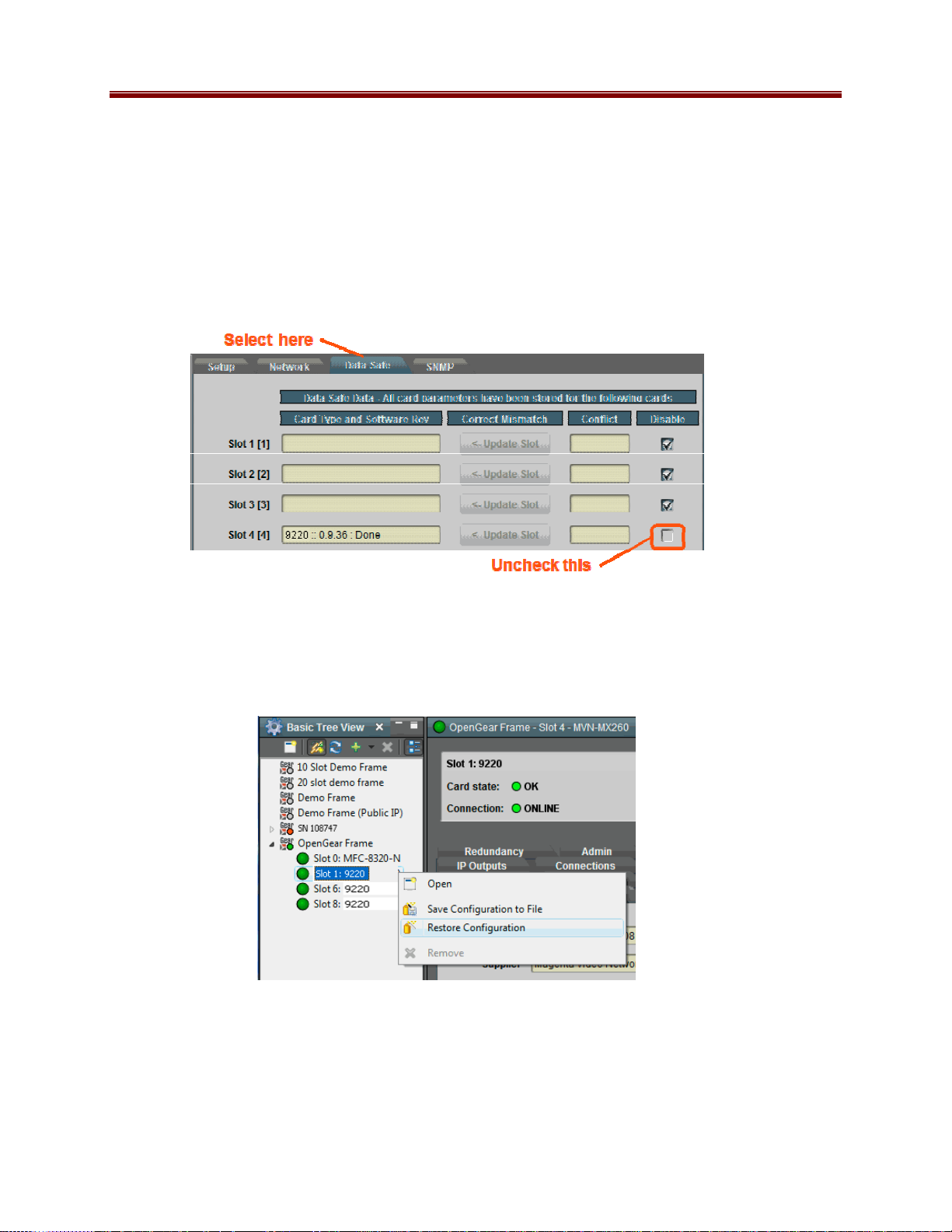
If you save a configuration to your computer, and later wish to restore it to the 9220, use the
following procedure:
1. On Dashboard™, open the user interface for the frame controller (slot 0).
2. Select the Data Safe tab in the configuration area.
3. Uncheck the Disable checkbox corresponding to the card you wish to restore the
configuration. This step is depicted below.
4. On the Dashboard™ Tree View, right-click on the card, and select Restore
Configuration. Follow the prompts and navigate to the file you wish to restore. This
process is illustrated below
This process is discussed in further detail in the Dashboard User Manual, chapter 5, section
Restoring Configurations to Devices.
52 9220-UM V1.1
Page 53

Pre-defined Templates
The 9220 offers 5 pre-defined configuration templates, as indicated below.
To load a template, just click on the Load button next to it. The pre-defined templates are;
• 6 ASI in ψψψψ 6 IP out (GbE 1): This template configures all six ASI Ports as inputs, and
connects them to six IP Outputs on Ethernet Port 1.
• 6 ASI in ψψψψ 6 IP out (GbE 2): This template configures all six ASI Ports as inputs, and
connects them to six IP Outputs on Ethernet Port 2.
• 6 IP in (GbE 1) ψψψψ 6 ASI out: This template configures all six ASI Ports as outputs, and
connects them to six IP Inputs from Ethernet Port 1.
• 6 IP in (GbE 2) ψψψψ 6 ASI out: This template configures all six ASI Ports as outputs, and
connects them to six IP Inputs from Ethernet Port 2.
• 3 IP In(GbE 2)ψψψψASI out, 3 ASIψψψψIP out(GbE 1): This template configures the first
three ASI Ports as outputs, and connects them to three IP Inputs from Ethernet Port 2. It
configures the remaining ASI Ports as inputs, and connects them to three IP Outputs on
Ethernet Port 1.
Clear Current Configuration Button
The Clear Current Configuration button clears all the configured ports and streams as follows:
• All ASI Ports are disabled.
• All IP Inputs are deleted.
• All IP Outputs are deleted.
• All Connections are removed.
• The Test Packet Generator is disabled.
The button does not affect the following areas:
• The settings in the Network tab are not changed.
• The settings in the Admin General tab are not changed.
• Saved configurations are not modified in any way.
Dashboard™ will take a few seconds to reload (longer if you are accessing over a wide-area
network), but the actual configuration in the 9220 is virtually instantaneous. The Status Message
Area will indicate the result of the operation.
53 9220-UM V1.1
Page 54

Admin Test Packet Generator Tab
The 9220 includes a Test Packet Generator (TPG) that is capable of generating a configurable
constant bit rate sequence of MPEG-2 Transport Packets with very strict timing. The TPG is
considered an input port, and is available to be connected to any output port. As with any input
in the 9220, it supports up to 8 connections. The user interface for the TPG is depicted below:
To configure the TPG, make your selections in the Modify Configuration area of the GUI, and
click on Apply Settings. The TPG configuration parameters are:
• Mode: controls the type of MPEG-2 transport packets generated. The options are:
o Disabled: TPG is disabled. No packets are being generated.
o NULL Packets: TPG is generating NULL packets. If you select this option, the
PID parameter becomes read-only with the value 1FFF.
o Ramp48 Packets: TPG is generating packets with a “Ramp48 Payload”. A
“Ramp48 Payload” is composed of the bytes 0x48, 0x49, 0x4A, …, 0xFF.
Generated packets have the Payload bit set, no Adaptation Field, and a valid
Continuity Counter field. On request, Cobalt Digital Inc. can supply a test
program for Windows or Linux that receives the Ramp48 packets and checks
them.
o PCR Pack e t s: TPG is generating packets with a valid PCR field (stamped
corresponding to the packet’s departure time at the configured bit rate). The
packets have a small payload with random data, so the Continuity Counter field is
valid and counting.
• PID (hex): controls the PID of the generated packets. This is specified in hexadecimal.
• Bit Rate (bps): controls the bit rate of the generated packets. The minimum value is
64,000 bps and the maximum value is 213,000,000 bps.
54 9220-UM V1.1
Page 55

Admin License Keys Tab
The 9220 has a number of optional licensable features. The Admin License Keys Tab is used to
manage these features. Using this tab, you can see how many licenses you have for each
optional feature, and how many you are currently using.
The 9220 has the concept of a temporary license. If you want to try out a certain feature, contact
Cobalt Digital Inc. You will receive a license key that enables that feature for a specific period
of running time (license time does not “count” when the card is off).
The Admin License Keys Tab includes a License Status table, and a configuration area, as shown
below. The table rows are license counts, and the columns correspond to different licensable
features. The rows are:
• Permanent Licenses: This is the number of non-expiring licenses for each feature.
• Temporary Licenses: This is the number of temporary licenses for each feature. Once
the license period expires, they are removed.
• Total Licenses: This is the total number of licenses for each feature. It is simply the sum
of the permanent and temporary licenses.
• Used Licenses: This is the number of licenses in use for each feature by the current card
configuration.
If you have temporary licenses, the Ti me R emaini ng field indicates how long until they expire.
If you do not have temporary licenses, this field has the message “No active temporary licenses”.
The table columns correspond to the licensable features, as follows:
• Enable GE2: Use of Ethernet Port 2 is subject to licensing. Only one license is required
to enable the port. This field will have 1 if Ethernet Port 2 is licensed or in use.
• TS Outputs: The 9220 requires one license per transport stream output (ASI or IP). This
column provides a count of outputs licensed and in use.
• The remaining columns correspond to features not yet available. Cobalt Digital Inc. if
you need more information, or if you want to be notified when they become available.
55 9220-UM V1.1
Page 56

If you want to request a license key from Cobalt Digital Inc., you will need to provide the card
serial number. It can be found in the Product Tab and in the Admin License Key Tab as well.
Once you receive the key from Cobalt Digital Inc., enter it in the License Key field shown
above, and click on the Apply License Key button. If the key is accepted, you will see the
message License Key Installed OK, as illustrated above. If there are any problems, you will see
an error message in the same location. The following are the possible error messages:
• Invalid key: missing characters: the key you entered is too short. Double-check that you
entered all the characters.
• Invalid/Corrupted Key: the key you entered has the correct number of characters, but it is
invalid. Double check what you entered.
• Serial number mismatch: this key is for serial xxxxxxxxxxxx: 9220 license keys are
specific to a card. You entered a valid license key, but it is intended for a different card,
whose serial number is displayed in the message. You must use this key on the correct
card.
• This key has already been applied: License keys can only be applied once. This is a
valid key for this card, but you have already applied it, and its features are already
available.
Admin Event Log Tab
The 9220 includes an Event Log in non-volatile storage. This event log can be used for faultfinding, and to check for error conditions. The following information is included in each 9220
event in the log:
• Date: The calendar date in which the event occurred.
• Time: The time at which the event occurred.
• Severity: The severity of the event. The 9220 defines three severity levels:
o Error: These are events that affect the operation of the device. For example, an
ASI Input loosing lock or an IP Input no longer receiving packets. An error will
impact service until addressed.
o Warning: These are events that may produce visible glitches, but they do not
have a continuous service impact. Examples of warnings are automatic
redundancy switches and ARP renewal failures.
o Info: These are informational events. All configuration actions are logged with
this severity. When an error is cleared (for example, an ASI Input regains lock),
the event is logged with this severity as well.
• Subsystem: The subsystem affected by the event. This may be a port, a stream, or the
card itself.
• Event: This is a textual description of the event.
The 9220 does not have a battery-backed real-time clock. It depends on the frame controller to
obtain the current date and time, and the frame controller depends on an external Network Time
Protocol (NTP) server to obtain current date and time. By default, the 9220 will initialize its
56 9220-UM V1.1
Page 57

internal time-of-day clock to January 1, 2010, GMT. If the frame controller is NTPsynchronized, the 9220 will then accept time from it and set its time-of-day clock accordingly.
In order to configure the frame controller for NTP, open its configuration screen on
Dashboard™, select the Network Tab, and enter the IP address of an available NTP server:
Select This
Configure
If your frame controller has access to the Internet, you can point it to one of the public NTP
servers for your region. You can find more details on this link:
http://psp2.ntp.org/bin/view/Servers/WebHome
The full Admin Event Log tab is displayed below:
57 9220-UM V1.1
Page 58

The fields are:
• Log Download: The user interface only displays the last 10 events of each type. If you
would like to see the whole event log, it can be downloaded to your computer by clicking
on the Save button. The log will be in CSV format, and it can be opened by any utility
that can read text files; ideally, you should use a spreadsheet program such as Microsoft
Excel or similar so it is presented in tabular format. The log will be in chronological
order, oldest entry to newest.
• Log View: The user interface can display the last 10 events. You can choose to see the
last 10 events of any kind by selecting All, or you can restrict the view only to Info,
Warning, or Error.
• Event Log: This table presents the last 10 events of the selected type.
• Time Zone: To simplify the correlation of the events with your local time, you can set
your time zone using this drop-down menu. Note that the 9220 presents a simplified list,
with standard GMT offsets. Note that standard GMT offsets do not change back and
forth with Daylight Savings; you will need to make this adjustment manually if it is
relevant to you.
58 9220-UM V1.1
Page 59

• Current Time: This field indicates the 9220 view of what the current date and time is. If
your frame is not NTP-synchronized, this is useful to figure out “how long ago did this
event happen”.
• Clear Log Display: If you click on this button, it clears all log views. This is useful to
quickly identify any new events after the unit has been set up. Note that this action does
not clear the logs stored in non-volatile memory.
The 9220 will store up to about 400 kBytes of logs in non-volatile memory. When that limit is
reached, the oldest half of the stored logs will be deleted to make space for new logs.
59 9220-UM V1.1
Page 60

Warranty and Repair Policy
Cobalt Digital Inc. Limited Warranty
This product is warranted to be free from defects in material and workmanship for a period of five
(5) years from the date of shipment to the original purchaser, except that 4000, 5000, 6000, 8000
series power supplies, and Dolby
defects in material and workmanship for a period of one (1) year.
Cobalt Digital Inc.'s (“Cobalt”) sole obligation under this warranty shall be limited to, at its
option, (i) the repair or (ii) replacement of the product, and the determination of whether a defect
is covered under this limited warranty shall be made at the sole discr e tion of Cobalt.
This limited warranty applies only to the original end-purchaser of t he product, and is not
assignable or transferrable therefrom. This warranty is limited to defects in material and
workmanship, and shall not apply to acts of God, accidents, or negligence on behalf of the
purchaser, and shall be voided upon the misuse, abuse, alteration, or modification of the product.
Only Cobalt authorized factory representatives are authorized to make repairs to the product, and
any unauthorized attempt to repair this product shall immediately void the warranty. Please
contact Cobalt Technical Support for more information.
To facilitate the resolution of warranty related issues, Cob alt recommends registering the product
by completing and returning a product registration form. In the event of a warrantable defect, the
purchaser shall notify Cobalt with a description of the problem, and Cobalt shall provide the
purchaser with a Return Material Authorization (“RMA”). For return, defective products should be
double boxed, and sufficiently protected, in the original packaging, or equivalent, and shipped to
the Cobalt Factory Service Center, postage prepaid and insured for the purchase price. The
purchaser should include the RMA number, description of the problem encountered, date
purchased, name of dealer purchased from, and serial number with the shipment.
®
modules (where applicable) are warranted to be free from
Cobalt Digital Inc. Factory Service Center
2406 E. University Avenue Office: (217) 344-1243
Urbana, IL 61802 USA Fax: (217) 344-1245
www.cobaltdigital.com Email: info@cobaltdigital.com
THIS LIMITED WARRANTY IS EXPRESSLY IN LIEU OF ALL OTHER WARRANTIES
EXPRESSED OR IMPLIED, INCLUDING THE WARRANTIES OF MERCHANTABILITY
AND FITNESS FOR A PARTICULAR PURPOSE AND OF ALL OTHER OBLIGATIONS OR
LIABILITIES ON COBALT'S PART. ANY SOFTWARE PROVIDED WITH, OR FOR USE
WITH, THE PRODUCT IS PROVIDED “AS IS.” THE BUYER OF THE PRODUCT
ACKNOWLEDGES THAT NO OTHER REPRESENTATIONS WERE MADE OR RELIED
UPON WITH RESPECT TO THE QUALITY AND FUNCTION OF THE GOODS HEREIN
SOLD. COBALT PRODUCTS ARE NOT AUTHORIZED FOR USE IN LIFE SUPPORT
APPLICATIONS.
COBALT'S LIABILITY, WHETHER IN CONTRACT, TORT, WARRANTY, OR
OTHERWISE, IS LIMITED TO THE REPAIR OR REPLACEMENT, AT ITS OPTION, OF
ANY DEFECTIVE PRODUCT, AND SHALL IN NO EVENT INCLUDE SPECIAL,
INDIRECT, INCIDENTAL, OR CONSEQUENTIAL DAMAGES (INCLUDING LOST
PROFITS), EVEN IF IT HAS BEEN ADVISED OF THE POSSIBILITY OF SUCH DAMAGES.
60 9220-UM V1.1
Page 61

Contact Us
Contact Cobalt Digital Inc.
General Business Office
PHONE
E-MAIL
POSTAL
SERVICE
and Technical Support
Fax
General Information
Sales Information
Cobalt Digital Inc.
Visit us at the Cobalt Digital Inc. website.
http://www.cobaltdigital.com/
• Online catalog
• Related products and full product lines
• Trade show information
• Dealer information
• Cobalt Digital Inc. news
217.344.1243
217.344.1245
Info@cobaltdigital.com
Sales@cobaltdigital.com
2406 East University Avenue
Urbana, IL 61802 USA
61 9220-UM V1.1
 Loading...