

Page 1
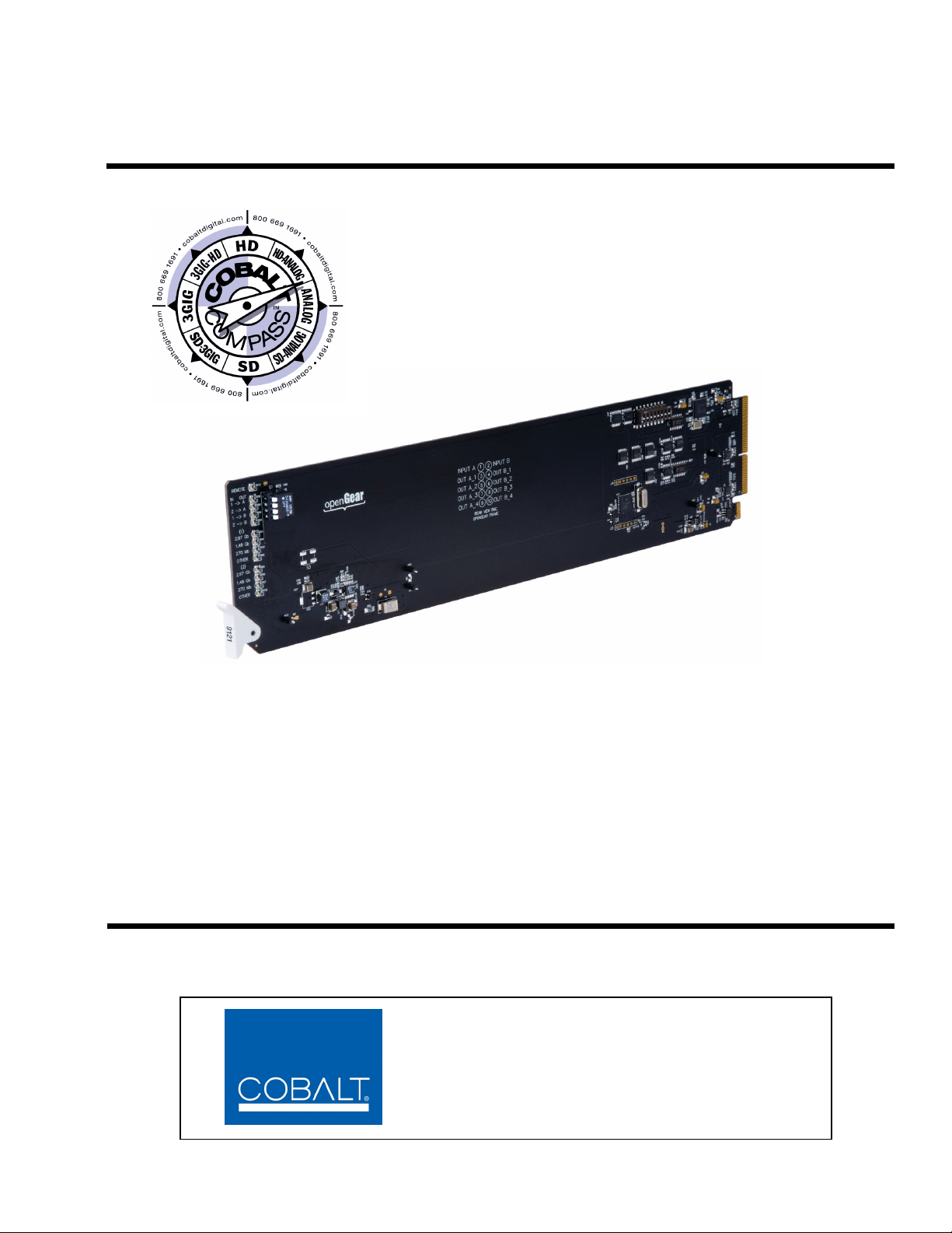
9121
3G/HD/SD-SDI / ASI Redundancy Switch
Product Manual
Cobalt Digital Inc.
2406 E. University Ave.
Urbana, IL 61802
Voice 217.344.1243 • Fax 217.344.1245
www.cobaltdigital.com
9121-OM (V1.2)
Page 2

Copyright
©Copyright 2013, Cobalt Digital Inc. All Rights Reserved.
Duplication or distribution of this manual and any information contained within is strictly prohibited without the express written
permission of Coba lt Digital Inc. This manual and a ny information contained within, may not be re produced, distribute d, or
transmitted in any form, or by any means, for any purpose, without the express written permission of Cobalt Digital Inc.
Reproduction or reverse engineering of software used in this device is prohibited.
Disclaimer
The information in this document has been carefully examined and is believed to be entirely reliable. However, no responsibility
is assumed for inaccuracies. Furthermore, C obalt Digit al Inc. res erves the right to ma ke changes to any pro ducts herein to improve
readability, function, or design. Cobalt Digital Inc. does not assume any liability arising out of the application or use of any
product or circuit described herein.
Trademark Information
Cobalt® is a registered trademark of Cobalt Digital Inc.
COMPASS
openGear
®
and Fusion3G® are registered trademarks of Cobalt Digital Inc.
®
is a registered trademark of Ross Video Limited. DashBoard™ is a trademark of Ross Video Limited.
Congratulations on choosing the Cob alt
a full line of modular processing and conversion gear for broadcast TV environments. The Cobalt Digital Inc.
line includes vide o de coders an d en code rs, aud io e mb edders an d d e-embe dde rs, dist ribu tio n am pli fiers, fo rmat
converters, remote contro l system s and much more. Shou ld you have qu estions pe rtainin g to the instal lation or
operation of your 9121, please contact us at th e contact inform ation on the front cove r.
®
9121 3G/HD/SD-SDI / ASI Redunda ncy Swit ch. The 9 121 is part of
Manual No.: 9121-OM
Document Version: V1.2
Release Date: October 7, 2013
Applicable for
Firmware Version
Rel 5
(or greater):
Description of
product/manual
changes:
- Update to include receive cable length
performance.
- Minor edits, updates to manual.
9121-OM (V1.2)
Page 3

Table of Contents
Chapter 1 Introduction . . . . . . . . . . . . . . . . . . . . . . . . . . . . . . . . . . . . . . . . . . . 1-1
Overview ................................................................................................................ 1-1
9121 Card Software Versions and this Manual...................................................... 1-2
Cobalt Reference Guides........................................................................................ 1-2
Manual Conventions............................................................................................... 1-3
Warnings, Cautions, and Notes .................................................................. 1-3
Labeling Symbol Definitions...................................................................... 1-4
Safety Summary ..................................................................................................... 1-4
Warnings..................................................................................................... 1-4
Cautions...................................................................................................... 1-4
9121 Functional Description .................................................................................. 1-5
User Control Interface ................................................................................ 1-6
9121 Rear I/O Modules .............................................................................. 1-6
Technical Specifications......................................................................................... 1-6
Warranty and Service Information ......................................................................... 1-8
Cobalt Digital Inc. Limited Warranty......................................................... 1-8
Contact Cobalt Digital Inc...................................................................................... 1-9
Chapter 2 Installation and Setup . . . . . . . . . . . . . . . . . . . . . . . . . . . . . . . . . . . 2-1
Overview ................................................................................................................ 2-1
Installing a Rear I/O Module.................................................................................. 2-1
9121 Rear I/O Modules .............................................................................. 2-1
Installing a Rear I/O Module...................................................................... 2-2
Connecting To GPI / GPO Phoenix Terminal Connectors..................................... 2-3
Installing the 9121 Into a Frame Slot ..................................................................... 2-5
Setting Up 9121 Network Remote Control ............................................................ 2-6
Chapter 3 Operating Instructions. . . . . . . . . . . . . . . . . . . . . . . . . . . . . . . . . . . 3-1
Overview ................................................................................................................ 3-1
Accessing the 9121 Card Using DashBoard™ Remote Control............................ 3-1
9121 Function Submenu List and Descriptions...................................................... 3-2
Input Select Control ................................................................................... 3-2
9121 Card Edge Control............................................................................. 3-4
Card Name ................................................................................................. 3-4
Troubleshooting...................................................................................................... 3-6
Error and Failure Indicator Overview ........................................................ 3-6
Basic Troubleshooting Checks................................................................... 3-6
Troubleshooting Network/Remote Control Errors..................................... 3-6
In Case of Problems.................................................................................... 3-6
9121-OM (V1.2) 9121 PRODUCT MANUAL i
Page 4

This page intentionally blank
9121-OM (V1.2) 9121 PRODUCT MANUAL ii
Page 5

Overview
Chapter 1
Chapter 1 Introduction
This manual provides installation and operating instructions for the 9121
3G/HD/SD-SDI / ASI Redundancy Switch ca rd ( al so re fe rr ed to herein as the
9121).
This manual consists of the following chapters:
• Chapter 1, “Introduction” – Provid es informa tion about this manual
and what is covered. Als o pr ovi des general information re gar di ng the
9121.
• Chapter 2, “Installation and Setup” – Provides instructions for
installing the 9121 in a frame, and optionally installing a 9121 Rear
I/O Module.
• Chapter 3, “Operating Instructions” – Provides overviews of
operating controls and instructions for using the 9121.
This chapter contains the following information:
• Manual Conventions (p. 1-3)
• Safety Summary (p. 1-4)
• 9121 Functional Description (p. 1-5)
• Technical Spe cification s (p. 1-6)
• Warranty and Service Information (p. 1-8 )
• Contact Cobalt Digital Inc. ( p. 1-9)
9121-O M (V1.2) 9121 PRODUCT MANUAL 1-1
Page 6

1 9121 Card Software Versions and this Manual
9121 Card Software Versions and this Manual
When applicable, Cobalt Digital Inc. provides for continual product
enhancements through software updates. As such, functions described in this
manual may pertain specifically to cards loaded with a particular software
build.
The Software Version of your card can be checked by viewing the Ca r d I n fo
menu in DashBoard™. You can then check our websi te fo r the late st softwa re
version currently released for the card as described below.
Check our website and proceed as follows if your card’s software does not
match the latest versi on:
Card Software earlier than
latest version
Card Software newer than
version in manual
Card is not loaded with the latest software. Not all
functions and/or specified performance described in
this manual may be available.
You can update your card with new Update
software by going to the Support>Firmware
Downloads link at www.cobaltdigital.com.
Download “Firmware Update Guide”, which
provides simple instructions for downloading the
latest firmware for your card onto your computer,
and then uploading it to your card through
DashBoard™.
Software updates are field-installed without any
need to remove the card from its frame.
A new manual is expediently released whenever a
card’s software is updated and specifications
and/or functionality have changed as compared
to an earlier version (a new manual is not
necessarily released if specifications and/or
functionality have not changed). A manual earlier
than a card’s software version may not completely
or accurately describe all functions available for
your card.
If your card shows features not described in this
manual, you can check for the latest manual (if
applicable) and download it by going to the
Support>Documents>Product Information and
Manuals link at www.cobaltdigital.com.
Cobalt Reference Guides
From the Cobalt® web home page, go to Support>Documents>Reference
Guides
updates, and other topics.
1-2 9121 PRODUCT MANUAL 9121-OM (V1.2)
for easy to use guide s covering network remot e control , card fir mware
Page 7

Introduction Manual Conventions
Manual Conventions
In this manual, display messages and connectors are shown using the exact
name shown on the 9121 itself. Examples are provided below.
• Connector and control names are shown like this: SDI IN A
In this manual, the terms below are applicable as follows:
• 9121 refers to the 9121 3G/HD/SD-SDI / ASI Redundancy Switch
card.
®
Compass®
Warnings, Cautions, and Notes
• Frame refers to the 20-slot frame that houses the Cobalt
and/or Fusion3G
• Device and/or Card refers to a Compass
• System and/or Video System refers to the mix of interconnected
®
cards.
®
or Fusion3G® card.
production and terminal equipment in which the 9121 and other
Compass
®
or Fusion3G® cards operate.
Certain items in this manual are highlighted by special messages. The
definitions are provided bel ow.
Warnings
Warning messages indicate a possible hazard which, if not avoided, could
result in pe rsonal injury or death.
Cautions
Caution messages indicate a problem or incorrect practice which, if not
avoided, could result in improper operation or damage to the product.
Notes
Notes provide supplemental information to the accompanying text. Notes
typically precede the text to which they apply.
9121-OM (V1.2) 9121 PRODUCT MANUAL 1-3
Page 8
1 Safety Summary
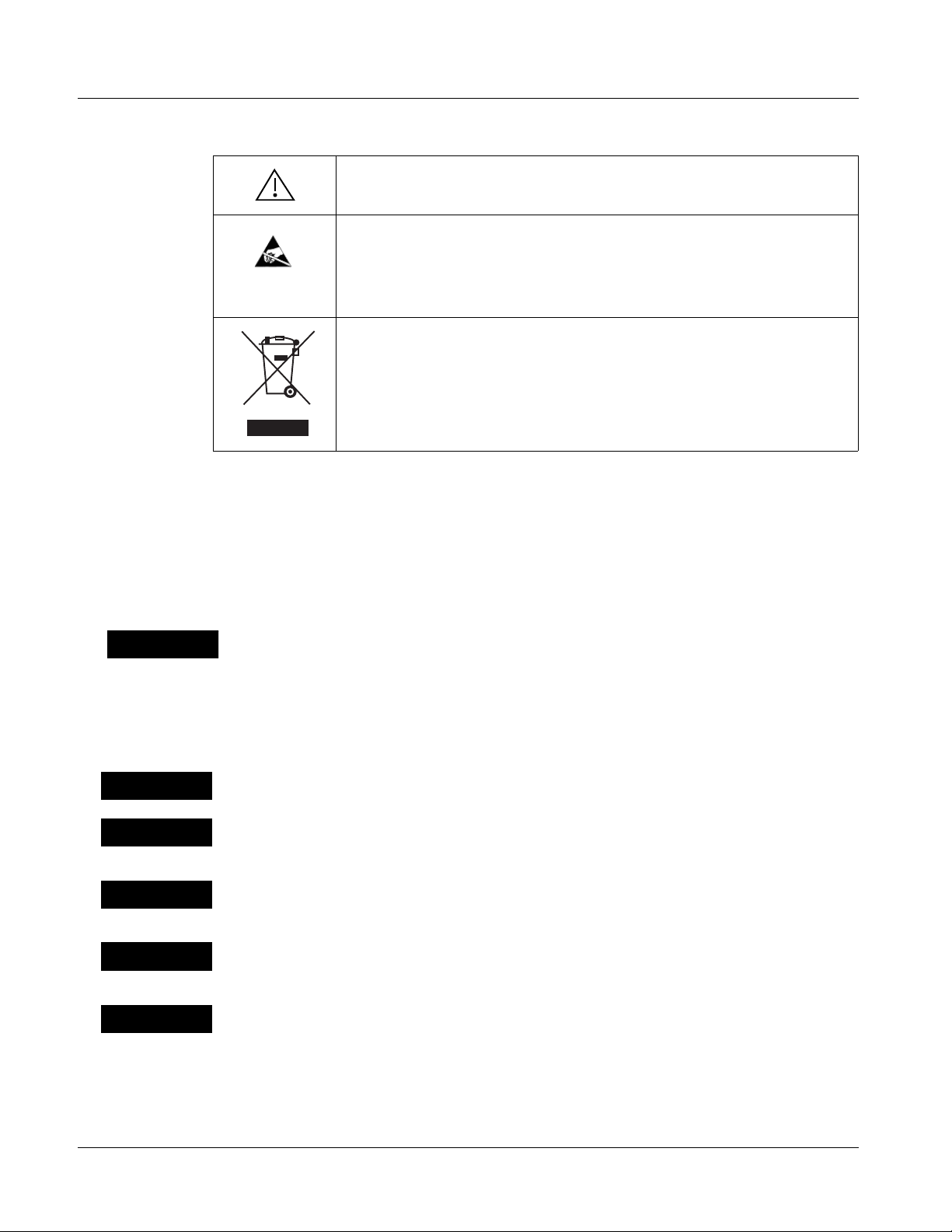
Labeling Symbol Definitions
Attention, consult accompanying documents.
Electronic device or assembly is susceptible to damage from an ESD
event. Han dle only using appropriate ESD prevention practices.
If ESD wrist strap is not available, handle card only by edges and avoid
contact with any connectors or components.
Symbol (WEEE 2002/96/EC)
For product disposal, ensure the following:
• Do not dispose of this product as unsorted municipal waste.
• Collect this product separately.
• Use collection and return systems available to you.
Safety Summary
Warnings
! WARNING !
Cautions
CAUTION
CAUTION
CAUTION
CAUTION
T o redu ce risk of electr ic shock do not remove line voltage service barrier cover on frame
equipment containing an AC power supply. NO USER SERVICEABLE PARTS INSIDE.
REFER SERVICING TO QUALIFIED SERVICE PERSONNEL.
This device is intended for environmentally controlled use only in appropriate video
terminal equipment operating environments.
This product is intended to be a component product of an openGear™ frame. Refer to the
openGear™ frame Owner's Manual for impor tant safety instructions regarding the proper
installation and safe operation of the frame as well as its component products.
Heat and power distribution requirements within a frame may dictate specific slot
placement of cards. Cards with many heat-producing components should be arranged to
avoid areas of excess heat build-up, particularly in frames using only convection cooling.
If required, make certain Rear I/O Module(s) is installed before installing the 9121 into the
frame slot. Damage to card and/or Rear I/O Module can occur if module installation is
attempted with card already installed in slot.
CAUTION
1-4 9121 PRODUCT MANUAL 9121-OM (V1.2)
If card resists fully engaging in r ear I/O module mating connector, check for alignment and
proper insertion in slot tracks. Damage to card and/or rear I/O module may occur if
improper card insertion is attempted.
Page 9

Introduction 9121 Functional Description
9121 Functional Description
Figure 1-1 shows a functi onal block diagram of the 9121. The 9121 3G/HD/
SD-SDI / ASI Redundancy Switch allo ws GPI or Ethernet/SNMP chan geover
control between two SDI or ASI sources to a common SDI or ASI output.
Output routing uses a latching relay to retain the selected I/O path even if the
card/frame is powered down or card is removed from its slot.
SDI / ASI
In A
SDI / ASI
In B
An SDI failover function is pr ovided using a ma in path preference of
If
SDI IN A goes invalid, then SDI IN B is selected. If SDI IN A goes valid again,
failover automatically reverts to the
SDI IN A input. Switchover can also be
SDI IN A:
manually selected (in which case the selection is persistent even if the card is
removed from its slot).
Note: Automatic failover operation is specified for supported SDI formats only.
Failover usage when carrying signals other than SDI should utilize the GPI
inputs controlled by suitable external monitoring devices.
The 9121 is very straightforward in operation in that the signal path is via a
direct relay path output (alternately, the selected input is available via
non-relay coupled 4x cable drivers). The relay signal path is entirely passive,
with the entire signal package kept intact with no modification of the signal.
Defeatable reclockers for the four non-relay outputs allow the card to p ass
digital signals other than SDI and ASI on these DA outputs.
Input Select
Latching Relay
(on Rear
Module)
Latched Relay
SDI / ASI Output
Signal Validi ty
Check
Software-Based
Monitor/Control
Ethernet Control
(DashBoard, SNMP)
GPO Status
GPI Contr ol
Figure 1-1 9121 Functional Block Diagram
9121-OM (V1.2) 9121 PRODUCT MANUAL 1-5
EQ/Reclock
4x DA
Outputs
9121BDV1.0LB68
Page 10

1 Technical Specifications
User Control Interface
9121 Rear I/O Modules
The 9121 uses DashBoard™ as the normal graphical user interface for the
card, similar to other Cobalt
®
Compass® or Fusion3G®cards.
The DashBoard™ software can be downloaded from the Cobalt Digital Inc.
website: www.cobaltdigital.com
(enter “DashBoard” in the search window).
The DashBoard™ user interface is described in Chapter 3,“Operating
Instructions”.
Note: If network remote control is to be used for the frame and the frame has not yet
been set up for remote control, Cobalt
User Guide (PN 9000RCS-RM) provides thorough information and
step-by-step instructions for setting up network remote control of Compass
cards using DashBoard™. (Cobalt
Remote Control Panel product manuals have complete instructions for setting
up remote control using a Remote Control Panel.)
Download a copy of this guide by clicking on the Support>Documents>
Reference Guides link at www.cobaltdigital.com and then select DashBoard
Remote Control Setup Guide as a download, or contact Cobalt
Contact Cobalt Digital Inc. (p. 1-9).
®
reference guide Remote Control
®
OGCP-9000 and OGCP-9000/CC
®
as listed in
®
The 9121 physically interfaces to system video connections at the rear of its
frame using a Rear I/O Module.
All inputs and outputs shown in the 9121 Functional Block Diagram (Figure
1-1) enter and exit the card via the card edge backplane connector. The
Rear I/O Module breaks out the 9121 card edge connections to BNC
connectors that interface with other components and systems in the signal
chain. Se e “Installation”, Chapter 2 for Rear I/O Module connections.
Technical Specifications
Table 1-1 lists the technical specifications for the 9121 3G/HD/SD-SDI / ASI
Redundancy Switch card.
Table 1-1 Technical Specifications
Item Characteristic
Part number, nomenclature 9121 3G/HD/SD-SDI / ASI Redundancy Switch
Installation/usage environment Intended for installation and usage in frame meeting openGear™
modular system definition.
Power consumption < 6 Watts maximum
Environmental:
Operating temperature:
Relative humidity (operating or storage):
Frame communication 10/100 Mbps Ethernet with Auto-MDIX.
32° – 104° F (0° – 40° C)
< 95%, non-condensing
1-6 9121 PRODUCT MANUAL 9121-OM (V1.2)
Page 11

Introduction Technical Specifications
Table 1-1 Technical Specifica tions — continued
Item Characteristic
Switchover Triggering Selectable automatic failover upon loss of valid SMPTE 425M,
292M, or 259M formatted signal. Manual switchover using
DashBoard remote control or GPI.
Note: Automatic failover operation is specified for supported SDI
formats only (see “Video Inputs” below). Failover usage when
carrying signals other than SDI should utilize the GPI inputs
controlled by suitable external monitoring devices.
Video Inputs Number of inputs: 2
Standards:
3G-SDI (SMPTE 425M)
HD-SDI (SMPTE 292M)
SD-SDI (SMPTE 259M)
Impedance: 75Ω
Receive Performance (EQ/Reclock
active path)
SD 370m 370m
Reclock ON
Reclock OFF
HD 190m 180m
3G 120m 100m
Note: Specification applicable only if using specified
current-manufacture Rear I/O Module.
Video Outputs Number of outputs:
(1) 75Ω BNC latching relay direct from selected input A or B
(4) 75Ω BNC non-relay DA (reclockable) via mux from selected
input A or B (213Mbit/s maximum ASI TS bit-rate per port)
Note: Relay output must be terminated into 75Ω impedance via
connection to downstream equipment or termination for card
to properly display input status.
GPI Two independent inputs that select input A or Input B.
Edge-triggering on H/L transition (switch closure or pull-down)
Response:
GPI acknowledge upon falling-edge input triggered
by R ≤ 10 kΩ (or Vin ≤ 2.0 V)
“G” (GND) terminal at chassis-ground potential
Suitable for use with 3.3V LVCMOS logic
Maximum Recommended Logic Control Voltage Range:
0 to 5 VDC
Connector: 3-terminal Phoenix; GPI-1/GPI-2/COM
GPO Two, independent non-referenced (floating) SPST relay closure
indicating input path selected (either via manual or failover
selection).
Response:
Closure effected for duration of t rue status condition; cl osure release
upon false status cond iti on
Maximum Recommended Voltage / Current:
12 VDC @ 100mA max.
Connector: 4-terminal Phoenix; GPO1/GPO1C / GPO2/GPO2C
9121-OM (V1.2) 9121 PRODUCT MANUAL 1-7
Page 12

1 Warranty and Service Information
Warranty and Service Information
Cobalt Digital Inc. Limited Warranty
This product is warranted to be free from defects in material and workmanship for a period of five (5)
years from the date of shipment to the original purchaser, except that 4000, 5000, 6000, 8000 series
power supplies, and Dolby
material and workmanship for a period of one (1) year.
Cobalt Digital Inc. 's (“Cobalt”) sole obligation under this warranty shall be limited to, at its option, (i)
the repair or (ii) replacement of the product, and the determinati on of whether a defect is covered under
this limited warranty shall be made at the sole discretion of Cobalt.
This limited warranty applies onl y to the original end-purchaser of the pr oduct, and is not assigna ble or
transferrable therefrom. This warranty is limited to defects i n material a nd workman shi p, and shal l not
apply to acts of God, accidents, or negligence on behalf of the purchaser, and shall be voided upon the
misuse, abuse, alteration, or modification of the product. Only Cobalt authorized factory
representatives are authorized to make repairs to the product, and any unauthorized attempt to repair
this product shall immediately void the warranty. Please contact Cobalt Technical Support for more
information.
®
modules (where applicable) are warranted to be free from defects in
To facilitate the resolution of warranty related issues , Cobalt recommends registering the product by
completing and returning a product registration form. In the event of a warrantable defect, the
purchaser shall notify Cobalt with a description of the problem, and Cobalt shall provide the purchaser
with a Return Material Authorization (“RMA”). For return, defective product s should be double boxed,
and sufficiently protected, in the original packaging, or equivalent, and shipped to the Cobalt Factory
Service Center, postage prepaid and insured for the purchase price. The purchaser should include the
RMA number, description of the problem encountered, date purchased, name of dealer purchased
from, and serial number with the shipment.
Cobalt Digital Inc. Factory Service Center
2406 E. University Avenue Office: (217) 344-1243
Urbana, IL 61802 USA Fax: (217) 344-1245
www.cobaltdigital.com Email: info@cobaltdigital.com
THIS LIMITED WARRANTY IS EXPRESSLY IN LIEU OF ALL OTHER WARRANTIES
EXPRESSED OR IMPLIED, INCLUDING THE WARRANTIES OF MERCHANTABILITY AND
FITNESS FOR A PARTICULAR PURPOSE AND OF ALL OTHER OBLIGATIONS OR
LIABILITIES ON COBALT'S PART. ANY SOFTWARE PROVIDED WITH, OR FOR USE WITH,
THE PRODUCT IS PROVIDED “AS IS.” THE BUYER OF THE PRODUCT ACK NOWLEDGES
THAT NO OTHER RE PRESENTATIONS WERE MADE OR RELIED UPON WIT H RESPECT TO
THE QUALITY AND FUNCTION OF THE GOODS HEREIN SOLD. COBALT PRODUCTS ARE
NOT AUTHORIZED FOR USE IN LIFE SUP PORT APPLICATIONS.
COBALT'S LIABILITY, WHETHER IN CONTRACT, TORT, WARRANTY, OR OTHERWISE, IS
LIMITED TO THE REPAIR OR REPLACEMENT, AT ITS OPTION, OF ANY DEFECTIVE
PRODUCT, AND SHALL IN NO EVENT INCLUDE SPECIAL, INDIRECT, INCIDENTAL, OR
CONSEQUENTIAL DAMAGES (INCL UDING LOST PROFITS), EVEN IF IT HAS BEEN
ADVISED OF THE POSSIBILITY OF SUCH DAMAGES.
1-8 9121 PRODUCT MANUAL 9121-OM (V1.2)
Page 13

Introduction Contact Cobalt Digital Inc.
Contact Cobalt Digital Inc.
Feel free to contact ou r th oro ugh and professional support representatives for
any of the following:
• Name and address of your local dealer
• Product information and pricing
• Technical support
• Upcoming trade show i nformation
Phone: (217) 344-1243
Fax: (217) 344-1245
Web: www.cobaltdigital.com
General Information: info@cobaltdigital.com
Technical Support: support@cobaltdigital.com
9121-OM (V1.2) 9121 PRODUCT MANUAL 1-9
Page 14

This page intentionally blank
1-10 9121 PRODUCT MANUAL 9121-OM (V1.2)
Page 15

Chapter 2 Installation and Setup
Overview
This chapter contains the following information:
• Installing a Rear I/O Module (p. 2-1)
• Connecting To GPI / GPO Phoenix Terminal Connectors (p. 2-3)
• Installing the 9121 Into a Frame Slot (p. 2-5)
• Setting Up 9121 Network Remote Control (p. 2-6)
Installing a Rear I/O Module
9121 Rear I/O Modules
Chapter 2
T able 2-1 shows and describes the Rear I/O Modules specifi cally for use with
the 9121.
9121-O M (V1.2) 9121 PRODUCT MANUAL 2-1
Page 16

2 Installing a Rear I/O Module
Table 2-1 9121 Rear I/O Modules
9121 Rear I/O Module Description
RM20-9121-B
Provides the following conne cti on s:
• IN A BNC input
• IN B BNC input
• RLY A/B OUT passive relay-coupled output.
Failover t o IN B if IN A is invalid. Manually selected
via user controls or SNMP.
Note: Relay output must be terminated into 75Ω
impedance via connection to downstream
equipment or termination for card to properly
display input status.
• Four non-relay outputs (OUT 1-1, 1-2, 1-3, and
OUT 2) with defeatable reclocking. All four
non-relay outputs track with RLY A/B OUT
selection.
• GPI inputs GPI1/G and GPI2/G for manual
selection of inputs IN A or IN B.
- GPI 1 invokes IN A
- GPI 2 invokes IN B
• GPI outputs GPO1 and GPO2 indicate input
channel selection (either invoked manually or via
failover).
- GPO 1 pair closed when IN A is selected
- GPO 2 pair closed when IN B is selected
CAUTION
GPO controlled circuit must not exceed voltage/
current ratings. See Technical Specifications (p. 1-6)
in Chapter 1, Introduction.
Installing a Rear I/O Module
Install a Rear I/O Module as follows:
1. On the frame, determine the slot in which the 9121 is to be installed.
2. In the mounting area corresponding to the slot location, install
Rear I/O Module as shown in Figure 2-1.
2-2 9121 PRODUCT MANUAL 9121-OM (V1.2)
Page 17

Installation and Setup Connecting To GPI / GPO Phoenix Terminal Connectors
Align and engage mounting tab on Rear
I/O Module with the module seating slot
1
on rear of frame chassis.
DSCN3483A.JPG
Hold top of Rear I/O Module flush against
frame chassis and start the captive screw.
2
Lightly tighten captive screw.
DSCN3487A.JPG
Figure 2-1 Rear I/O Module Installation
Connecting To GPI / GPO Phoenix Terminal Connectors
Figure 2-2 shows connections to the card Phoenix™ terminal block GPI and
GPO connectors. These terminal blocks use a removable screw terminal
binding post block which allows easier access to the screw terminals.
Note: It is preferable to wire connections to Phoenix plugs oriented as shown in
Figure 2-2
that the orientation of rear module connectors is not necessarily consistent
within a rear module, or between different rear modules. If wiring is first connected to Phoenix plug oriented as shown here, the electrical orientation will
be correct regardless of rear module connector orientation.
rather than assessing polarity on rear module connectors. Note
9121-OM (V1.2) 9121 PRODUCT MANUAL 2-3
Page 18

2 Connecting To GPI / GPO Phoenix Terminal Connectors
Rear module
PCB connector
Rear module
PCB connector
12G
Selects IN A when
Selects IN B when
C12C
GPI Port Connections
Removable Phoenix plug view oriented
with top (screw terminals) up
Note: GPI functional only when card is set to
manually use IN A or IN B (GPI selects
alternate input of whatever input is
currently selected). GPI is locked out
when Failover is selected for output
routing.
GPO Port Connections
Closes when IN A
is selected
Closes when IN B
is selected
Figure 2-2 GPI/GPO Phoenix Termina l Connect ions
Removable Phoenix plug view oriented
with top (screw terminals) up
GPO controlled circuit must
not exceed voltage/current
ratings. See Technical
Specifications (p. 1-6) in
Chapter 1, Introduction.
2-4 9121 PRODUCT MANUAL 9121-OM (V1.2)
Page 19

Installation and Setup Installing the 9121 Into a Frame Slot
Installing the 9121 Into a Frame Slot
CAUTION
Heat and power distribution requirements within a frame may dictate specific
slot placement of cards. Cards wi th many he at-producing com ponent s shoul d
be arranged to avoid areas of excess heat build-up, particularly in frames
using only convection cooling.
CAUTION
This device contains semiconductor devices which are
susceptible to serious damage from Electrostatic
Discharge (ESD). ESD damage may not be immediately
apparent and can affect the long-term reliability of the
device.
Avoid handling circuit boards in high static environments
such as carpeted areas, and when wearing synthetic fiber
clothing. Always use proper ESD handling precautions
and equipment when working on circuit boards and
related equipment.
Note: A Rear I/O Module is required before cabling can be connected. Refer to
Installing a Rear I/O Module (p. 2-1) for rear I/O module installation procedure.
CAUTION
If required, make certain Rear I/O Module(s) is installed before installing the
9121 into the frame slot. Damage to card and/or Rear I/O Module can occur if
module installation is attempted with card already installed in slot.
Note: Check the packaging in which the 9121 was shipped for any extra items such
as a Rear I/O Module connection label. In some cases, this label is shipped
with the card and to be installed on the Rear I/O connector bank corresponding to the slot location of the card.
Install the 9121 into a frame slot as follows:
1. Determine the slot in which the 9121 is to be installed.
2. Open the frame front access panel.
3. While holding the card by the card edges, align the card such that the
plastic ejector tab is on the bottom.
4. Align the card with the top and bottom guides of the slot in which the
card is being installed.
5. Gradually slide the card into the slot. When resistance is noticed, gently
continue pushing the card until its rear printed circuit edge terminals
engage fully into the rear I/O module mating connector.
9121-OM (V1.2) 9121 PRODUCT MANUAL 2-5
Page 20

2 Setting Up 9121 Network Remote Control
CAUTION
If card resists fully engaging in rear I/O module mating connector, check for
alignment and proper insertion in slot tracks. Damage to card and/or rear I/O
module may occur if improper card insertion is attempted.
Verify that the card is fully engaged in rear I/O module mating
6.
connector.
7. Close the frame front access panel.
8. Connect the input and output cables as shown in Installing a Rear I/O
Module (p. 2-2).
9. Repeat steps 1 through 8 for other 9121 cards.
Note: To remove a card, press down on the ejector tab to unseat the card from the
rear I/O module mating connector. Evenly draw the card from its slot.
10. I f network remote control is to be used for the fram e and the frame has
not yet been set up for remote contro l, pe rf orm set up in accordance with
Setting Up 9121 Network Remote Control (p. 2-6).
Note: If installing a card in a frame already equipped for, and connected to
DashBoard™, no network setup is required for the card. The card will be discovered by DashBo ard™ and be ready for use.
Setting Up 9121 Network Remote Control
Perform remote control setup in accordance with Cobalt® reference guide
“Remote Control User Guide” (PN 9000RCS-RM).
Note: • If network remote control is to be used for the frame and the frame has not
yet been set up for remote control, Cobalt
Control User Guide (PN 9000RCS-RM) provides thorough information and
step-by-step instructions for setting up network remote control of
COMPASS™ cards using DashBoard™. (Cobalt
OGCP-9000/CC Remote Control Panel product manuals have complete
instructions for setting up remote control using a Remote Control Panel.)
Download a copy of this guide by clicking on the
Support>Documents>Reference Guides link at www.cobaltdigital.com
and then select DashBoard Remote Control Setup Guide as a download, or
contact Cobalt
• If installing a card in a frame already equipped for, and connected to
DashBoard™, no network setup is required for the card. The card will be discovered by DashBoard™ and be ready for use.
®
as listed in Contact Cobalt Digital Inc. (p. 1-9).
®
reference guide Remote
®
OGCP-9000 and
2-6 9121 PRODUCT MANUAL 9121-OM (V1.2)
Page 21

Overview
Chapter 3
Chapter 3 Operating Instructions
This chapter contains the following information:
If you are already familiar
with using DashBoard or a
Cobalt Remote Control
Panel to control Cobalt
cards, please skip to 9121
Function Submenu Li st and
Descriptions (p. 3-2).
• Accessing the 9121 Card Using DashBoard™ Remote
Control (p. 3-1)
• 9121 Function Submenu List and Descriptions (p. 3-2)
• Troubleshooting (p. 3-6)
Accessing the 9121 Card Using Das hBoard™ Remote Control
1. On the computer connected to the frame LAN, open DashBoard ™.
2. As shown below, in the left side Basic View Tree locate the Network
Controller Card associated with the frame containing the 9121 card to be
accessed (in this example, “MFC-8320-N SN: 00108053”).
DB_ACCESS1.PNG
9121-O M (V1.2) 9121 PRODUCT MANUAL 3-1
Page 22

3 9121 Function Submenu List and Descriptions
3. As shown below, expand the tree to access the cards within the frame.
Click on the card to be accessed (in this example,
.
“Slot 6: CDI-9121”).
9121_DB_ACCESS2A.PNG
When the ca rd is accessed in DashBoard™ its function submenu screen
showing tabs for each function is displayed.
9121 Function Submenu List and Descriptions
T abl e 3-1 in div idual ly lists and descri bes ea ch 9121 f uncti on submenu a nd its
related list selections, controls, and parameters. Where helpful, examples
showing usage of a function are also provided. Table 3-1 is primarily based
upon using DashBoard™ to access each function and its corresponding
submenus and parameters.
Table 3-1 9121 Func tion Subme nu List
Shows card selection to use card edge control or
Input Select Control
• Card Remote Control / Card Edge Control
Select
DashBoard™ remote control.
• Enabled shows DashBoard remote control and status monitoring for
card functions has been enabled.
• Disabled shows DashBoard remote control has been locked out. In
this mode DashBoard only shows status, with control effected using
card edge switches.
Note: Card default settings enable remote control. Refer to 9121
Card Edge Control (p. 3-4) for using card edge control.
3-2 9121 PRODUCT MANUAL 9121-OM (V1.2)
Page 23

Operating Instructions 9121 Function Submenu List and Descriptions
Table 3-1 9121 Function Submenu List — continued
Provides input status and routing controls for manual or
failover routing to the relay output and non-relay
reclockable outputs.
• Input Status Shows input status of SDI Input A and Input B as follows:
• SDI format (for example, “720p/5994” as shown to the left) indicates
input recognizes a valid SDI format supported by the card.
• Unlocked indicates input does not recognizes a valid SDI format
supported by the card. This can be from loss of signal presence or a
signal format that is not supported SMPTE 425M, SMPTE 292M, or
SMPTE 259M signals recognized by the card (such as ASI or AES
audio).
Note: Card relay output RLY A/B OUT must be terminated into 75Ω
impedance via connection to downstream equipment or termination
for card to properly display input status.
• Output Select and Status Selects (either manually or via failover rules) input-to-output routing of the
two inputs to the card RLY A/B OUT port and the four OUT non-relay ports
as follows:
• Input A or Input B selection provides corresponding manual selection
of input. In this mode, GPI can select the alternate input when applied.
• Fail Over selection provides main path preference of Input A .
- If Input A goes invalid, then Input B is selected.
- If Input A goes valid again, failover automatically reverts to Input A.
Note: If an input is being sourced from a digital signal other than a
supported SMPTE 425M, SMPTE 292M, OR SMPTE 259M signal
(such as ASI or AES audio), unlocked will be displayed. Failover
cannot reliably be used when passing these signals. Input select
should only use manual selection. Failover usage when carrying
signals other than SDI should utilize the GPI inputs controlled by
suitable external monitoring devices.
• Output Stat us s hows input routing currently invoked (either by manual/
GPI selection or by failover), as well as signal status.
Example here shows manual (forced) selection with Input A not present
(or not recognized as valid).
Example here shows failover from Input A to Input B upon unlock of
Input A.
9121-OM (V1.2) 9121 PRODUCT MANUAL 3-3
Page 24

3 9121 Function Submenu List and Descriptions
Table 3-1 9121 Func tion Subme nu List — continued
(continued)
• Reclock Enable Select For the four non-relay outputs (OUT 1-1 thru OUT 2), allows reclock
Card Name
9121 Card Edge Control
enable/disable for outputs sourced from Input A or Input B.
Note: If input is not carrying a valid SDI format supported by the card,
control should be set to Disabled. This allows passage of non-SDI
digital signals such as ASI or AES audio.
Provides entry field for custom card name/ID.
Allows up to 15 characters to be entered for card ID (in this example “IRD
1A23-24 SW”).
Entered name appears in DashBoard card info header as well as
DashBoard frame tree view.
Card edge control allows limited use of c ard witho ut re mote co ntrol, or can be
used where remote control is desired to be locked out.
Figure 3-1 shows and describes the 9121 card edge controls, indicators, and
display.
3-4 9121 PRODUCT MANUAL 9121-OM (V1.2)
Page 25

Operating Instructions 9121 Function Submenu List and Descriptions
Mode/RCK Select Switch
Remote (RMT)
Status
LED
Input Select Switch
1234
Input A
Status
LEDs
Input B
Status
LEDs
AB
A
Sel
LED
Item Function
Mode/RCK
Select
switches
Input Select
switch
4-position piano switch selects the following:
• (1) UP – Card Edge Control Enabled (DashBoard disabled) –
DOWN – Card Edge Control Disabled (DashBoard enabled)
• (2) Reserved
• (3) UP – Input A Reclocking Disabled
DOWN – Input A Reclocking Enabled
• (4) UP – Input B Reclocking Disabled
DOWN – Input B Reclocking Enabled
After ARM button is pressed, allows input routing as follows:
• LEFT – select Input A
• RIGHT – select Input B
ARM Switch
B
Sel
LED
9121
ARM
Sel
LED
ARM
pushbutton
Remote
(RMT) Status
indicator
Input A
Status
Input B
Status
indicators
A Sel
B Sel
indicators
ARM Sel
indicator
When pressed, allows input select as described above (times out after appr. 8 seconds)
When illuminated, remote control is enabled
Three blue LEDs indicate the input signal format being received and locked onto by the 9121:
• 3G
• HD
• SD
Continuous cycling of the LEDs indicates the 9121 has not locked onto a particular format (as in the case of no
signal input or unrecognized signal type).
Indicates input (A or B) currently routed to outputs
Indicates Input Select switch is armed
Figure 3-1 9121 Card Edge Controls and Indicators
9121-OM (V1.2) 9121 PRODUCT MANUAL 3-5
Page 26

3 Troubleshooting
Troubleshooting
This section provides general troubleshooting information and specific
symptom/corrective action for the 9121 card and its remote control interface.
The 9121 card requires no periodic maintenance in its normal operation; if
any error indication (as described in this section) occurs, use this section to
correct the condition.
Error and Failure Indicator Overview
The 9121 card itself and its remote control systems all (to varying degrees)
provide error and failure indications. Depending on how the 9121 card is
being used (i.e, standalone or network controlled through DashBoard™),
check all available indications in the event of an error or failure condition.
Red indicators in DashBoard typically signify a condition where the card is
lacking a required input, or controls are improperly set for the mode(s)
selected.
Basic Troubleshooting Checks
Failures of a general nature (affecting many cards and/or functions
simultaneously), or gross inoperability errors are best addressed first by
performing basic checks before proceeding further. Tables 3-2 and 3-2
provide basic system checks that typically locate the source of most general
problems.
Troubleshooting Network/Remote Control Errors
Refer to Cobalt® reference guide “Remote Control User Guide” (PN
9000RCS-RM) for network/remote control troubleshooting information.
In Case of Problems
Should any problem arise with this product that was not solved by the
information in this section, please contact the Cobalt Digital Inc. Technical
Support Department.
If required, a Return Material Authorization number (RMA) will be issued to
you, as well as specific shipping instructions. If required, a temporary
replacement item will be made available at a nominal charge. Any shipping
costs incurred are the customer’s responsibility. All products shipped to you
from Cobalt Digital Inc. will be shipped collect.
The Cobalt Digital Inc. Technical Support Department will continue to
provide advice on any product manufactured by Cobalt Digital Inc., beyond
the warranty period without charge, for the life of the product.
See Contact Cobalt Digital Inc. (p. 1-9) in Chapter 1, “Introduction“ for
contact in formation.
3-6 9121 PRODUCT MANUAL 9121-OM (V1.2)
Page 27

Operating Instructions Troubleshooting
Table 3-2 Basic Troubleshooting Checks
Item Checks
Verify power presence and
characteristics
Check Cable connection
secureness and connecting
points
Card seating within slots Make certain all cards are properly seated within its frame slot. (It is best to assure
Check status indicators and
displays
Troubleshoot by substitution All cards within the frame can be hot-swapped, replacing a suspect card or module
Table 3-3 Troubleshooting Processing Errors by Symptom
On both the frame Network Controller C ard and the 9121 , in all cases wh en powe r is
being properly supplied there is always at least one indicator illuminated. Any card
showing no illuminated indicators should be cause for concern.
Make certain all cable connections are fully secure (including coaxial cable
attachment to cab le fe rrule s on BN C con nec tors ). Als o, m ak e ce rt ai n al l co nne cting
points are as intend ed. Mak e ce rtain the selected connecting points correlate to the
intended card inputs and/or outputs. Cabling mistakes are especially easy to make
when working with large I/O modules.
proper seating by ejecting the card and reseating it again.)
On DashBoard™, red indications typically signify an error condition. If a status
indicator signifies an error, proceed to the following tables in this section for further
action.
with a known-good item.
Symptom Error/Condition Corrective Action
DashBoard™ remote control
does not change card settings .
Remote control disabled on
card
Check card edge Mode Selec t switch and make
certain set for Card Edge Control>Disabled
(see 9121 Card Edge Control (p. 3-4)).
DashBoard™ remote control is locked out if
card edge control is enabled.
• DashBoard™ indicates
Unlocked for input.
• Card edge Input Format LEDs
show continuous cycling.
Failover does not function as
expected.
Card non-relay outputs will not
pass selected input.
Card Input Status displays show
unlocked when receiving a valid
SDI signal
• No video input present • Make certain intended video source is
connected to appropriate card video input.
Make certain BNC cable connections
between frame Rear I/O Module for the card
and signal source are OK.
• Signal is not SMTE 425,
292M, or 259
Signal not supported by card
failover validity check
Reclocking enabled for
non-SDI signal
Relay output RL Y A/B OUT
unterminated
• The card can typica lly pass non-SDI signals,
however, status will indicate Unlocked.
Only signal formats recognized by the card
validity checks should use the failover mode.
(See Technical Specifications (p. 1-6))
Reclocking should be disabled if non-relay
outputs are to carry any non-SDI signal. (See
Technical Specifications (p. 1-6))
Card relay output RLY A/B OUT must be
terminated into 75Ω impedance via connection
to downstream equipment or termination for
card to properly display input status.
9121-OM (V1.2) 9121 PRODUCT MANUAL 3-7
Page 28

This page intentionally blank
3-8 9121 PRODUCT MANUAL 9121-OM (V1.2)
Page 29

Page 30

Cobalt Digital Inc.
2406 E. University Ave.
Urbana, IL 61802
Voice 217.344.1243 • Fax 217.344.1245
www.cobaltdigital.com
9121-OM (V1.2) Printed in USA
 Loading...