

Page 1
9085
HD/SD Loudness Processor
with Audio-Video Delay Correction
9085-LP51 – 5.1-Channel Loudness Processor with Embedded-De-Embedder
9085-2LP20 – Dual Stereo Loudness Processor with Embedded-De-Em bedder
9085-LP20 – Single Stereo Loudness Processor with Embedded-De-Embedder
Product Manual
Cobalt Digital Inc.
2406 E. University Ave.
Urbana, IL 61802
Voice 217.344.1243 • Fax 217.344.1245
www.cobaltdigital.com
9085-OM (V4.3)
Page 2

Copyright
©Copyright 2013, Cobalt Digital Inc. All Rights Reserved.
Duplication or distribution of this manual and any information contained within is strictly prohibited without the express written
permission of Coba lt Digital Inc. This manual and a ny information contained within, may not be re produced, distribute d, or
transmitted in any form, or by any means, for any purpose, without the express written permission of Cobalt Digital Inc.
Reproduction or reverse engineering of software used in this device is prohibited.
Disclaimer
The information in this document has been carefully examined and is believed to be entirely reliable. However, no responsibility
is assumed for inaccuracies. Furthermore, C obalt Digit al Inc. res erves the right to ma ke changes to any pro ducts herein to improve
readability, function, or design. Cobalt Digital Inc. does not assume any liability arising out of the application or use of any
product or circuit described herein.
Trademark Information
Cobalt® is a registered trademark of Cobalt Digital Inc.
COMPASS
openGear
Dolby
property of their respective owners.
Linear Acoustic
AEROMAX
AutoMAX, AutoMAX-II, and AEROMAX
®
and FUSION3G® are registered trademarks of Cobalt Digital Inc.
®
is a registered trademark of Ross Video Limited. DashBoard™ is a trademark of Ross Video Limited.
®
is a registered trademark of Dolby Laboratories, Inc. Other product names or trademarks appearing in this manual are the
®
and AEROMAX® are registered trademarks of Linear Acoustic, Inc. Loudness processor licensed feature uses
®
algorithms provided under lic ense from Linear Acoustic Inc. Linear Acoustic, the "LA" symbol, UPMAX,
®
are trademarks of Linear Acoustic Inc. All Rights Reserved.
®
Congratulations on choosing the Cobalt
9085 HD/SD Loudness Processor with Audi o-Video Delay Correction. The
9085 is part of a full line of modula r processing and conversion gear for broadcast TV environments. The Cobalt
Digital Inc. line includes video decoders and encoders, audio embedders and deembedders, distribution amplifiers,
format converters, remot e control systems and much more. Shoul d you have qu estions pertain ing to the installat ion or
operation of your 9085, please contact us at th e contact inform ation on the front cove r.
Manual No.: 9085-OM
Document Version: V4.3
Release Date: January 15, 2013
Applicable for
Firmware Version
3302
(or greater):
Description of
product/manual
changes:
- Update to add new Rear I/O Module.
- Revise manual to reflect latest functionality per
recent firmware releases.
9085-OM (V4.3)
Page 3

Table of Contents
Chapter 1 Introduction . . . . . . . . . . . . . . . . . . . . . . . . . . . . . . . . . . . . . . . . . . . 1-1
Overview ................................................................................................................ 1-1
9085 Card Software Versions and this Manual...................................................... 1-2
Cobalt Reference Guides........................................................................................ 1-2
Manual Conventions............................................................................................... 1-3
Warnings, Cautions, and Notes .................................................................. 1-3
Labeling Symbol Definitions...................................................................... 1-4
Safety Summary ..................................................................................................... 1-4
Warnings..................................................................................................... 1-4
Cautions...................................................................................................... 1-4
9085 Functional Description .................................................................................. 1-5
9085 Input/Output Formats ........................................................................ 1-5
Video Functions Description...................................................................... 1-7
Audio Processor Description...................................................................... 1-8
AES Audio Input Advanced Features ...................................................... 1-13
Dolby Decoding Option (+DEC).............................................................. 1-13
User Control Interface .............................................................................. 1-14
9085 Rear I/O Modules ............................................................................ 1-16
Audio and Video Formats Supported by the 9085................................... 1-17
Technical Specifications....................................................................................... 1-18
Warranty and Service Information ....................................................................... 1-21
Cobalt Digital Inc. Limited Warranty....................................................... 1-21
Contact Cobalt Digital Inc.................................................................................... 1-22
Chapter 2 Installation and Setup . . . . . . . . . . . . . . . . . . . . . . . . . . . . . . . . . . . 2-1
Overview ................................................................................................................ 2-1
Setting I/O Switches for AES I/O (1-4) Ports ........................................................ 2-1
Installing the 9085 Into a Frame Slot ..................................................................... 2-2
Installing a Rear I/O Module.................................................................................. 2-4
9085 Rear I/O Modules .............................................................................. 2-6
Setting Up 9085 Network Remote Control .......................................................... 2-11
Chapter 3 Operating Instructions. . . . . . . . . . . . . . . . . . . . . . . . . . . . . . . . . . . 3-1
Overview ................................................................................................................ 3-1
Control and Display Descriptions........................................................................... 3-1
Function Submenu/Parameter Submenu Overview.................................... 3-2
DashBoard™ User Interface....................................................................... 3-3
Cobalt
®
Remote Control Panel User Interfaces.......................................... 3-4
9085-OM (V4.3) 9085 PRODUCT MANUAL i
Page 4

Accessing the 9085 Card via Remote Control........................................................ 3-5
Accessing the 9085 Card Using DashBoard™ ........................................... 3-5
Accessing the 9085 Card Using a Cobalt® Remote Control Panel ............. 3-6
Checking 9085 Card Information............................................................................ 3-7
Ancillary Data Line Number Locations and Ranges .............................................. 3-8
9085 Function Submenu List and Descriptions...................................................... 3-9
Audio Input Controls ................................................................................ 3-10
Video Proc ................................................................................................ 3-12
AFD .......................................................................................................... 3-13
Audio/Video Resync (Framesync tab) ..................................................... 3-14
Embedded Audio Group 1/2 .................................................................... 3-19
Embedded Audio Group 3/4 .................................................................... 3-23
AES Audio Out Pairs 1-4 ......................................................................... 3-25
AES Audio Out Pairs 5-8 ......................................................................... 3-29
Audio LKFS Monitor ............................................................................... 3-30
Timecode .................................................................................................. 3-32
Tone Generator ......................................................................................... 3-35
Audio Mixing ........................................................................................... 3-36
Audio Loudness Processing ..................................................................... 3-38
Licensable Features .................................................................................. 3-40
Presets ...................................................................................................... 3-40
Example Setups Using The 9085 and DashBoard™ ............................................ 3-43
Audio Routing Example Using DashBoard™ .......................................... 3-43
Troubleshooting .................................................................................................... 3-46
Error and Failure Indicator Overview....................................................... 3-46
Basic Troubleshooting Checks.................................................................. 3-50
9085 Processing Error Troubleshooting.................................................... 3-51
Troubleshooting Network/Remote Control Errors.................................... 3-53
In Case of Problems .................................................................................. 3-53
Appendix A Loudness Measurement Guidelines and Techniques. . . . . . . . . . A-1
About Loudness Measurement Applied to Program Material ............................... A-1
About Target LKFS Value..................................................................................... A-2
Measurement Techniques For Various Program Material Forms.......................... A-3
Importance of an Anchor Element ............................................................. A-4
Assumptions and Conditions For Meaningful LKFS Measurements........ A-4
Specific Measurement Techniques for Various Material Forms ............... A-6
Modifying LKFS Assessments Using Parametric Settings........................ A-7
ii 9085 PRODUCT MANUAL 9085-OM (V4.3)
Page 5

Overview
Chapter 1
Chapter 1 Introduction
This manual provides installation and operating instructions for the 9085
HD/SD Loudness Processor with Audio-Video Delay Correction card (also
referred to herein as the “9085”).
Note: This manual covers the three models of the 9085 card, which vary only in the
loudness processor channel capacity as follows:
• 9085-LP51 – 5.1-Channel Loudness Processor
• 9085-2LP20 – Dual Stereo Loudness Processor
• 9085-LP20 – Single Stereo Loudness Processor
Where applicable, descriptions related exclusively to s pecific models are
denoted by (9085-LP51 only), (9085-2LP20 only), or (9085-LP20 only). In all
other aspects, the cards function identically as described in this manual.
This manual consists of the following chapters:
• Chapter 1, “Introduction” – Provid es informa tion about this manual
and what is covered. Als o pr ovi des general information re gar di ng the
9085.
• Chapter 2, “Installation and Setup” – Provides instructions for
installing the 9085 i n a fr ame, and option ally i nsta lling 9085 Rear I/O
Modules.
• Chapter 3, “Operating Instructions” – Provides overviews of
operating controls and instructions for using the 9085.
This chapter contains the following information:
• 9085 Card Software Versions and this Manual (p. 1-2)
• Manual Conventions (p. 1-3)
• Safety Summary (p. 1-4)
• 9085 Functional Description (p. 1-5)
• Technical Spe cification s (p. 1-18)
• Warranty and Service Information (p. 1-21)
• Contact Cobalt Digital Inc. ( p. 1-22)
9085-O M (V4.3) 9085 PRODUCT MANUAL 1-1
Page 6

1 9085 Card Software Versions and this Manual
9085 Card Software Versions and this Manual
When applicable, Cobalt Digital Inc. provides for continual product
enhancements through software updates. As such, functions described in this
manual may pertain specifically to cards loaded with a particular software
build.
The Software Version of your card can be ch eck ed by vi ewi ng the Card Inf o
menu in DashBoard™. See Checking 9085 Card Information (p. 3-7) in
Chapter 3, “Operating Instructio ns” for more infor mation. You can then check
our website for the lates t software version currently released for the card as
described below.
Check our website and proceed as follows if your card’s software does not
match the latest versi on:
Card Software earlier than
latest version
Card Software newer than
version in manual
Card is not loaded with the latest software. Not all
functions and/or specified performance described in
this manual may be available.
You can update your card with the new Update
software by going to the Support>Firmware link at
www.cobaltdigital.com. Download “Firmware
Update Guide”, which provides simple instructions
for downloading the latest firmware for your card
onto your computer, and then uploading it to your
card through DashBoard™.
Software updates are field-installed without any
need to remove the card from its frame.
A new manual is expediently released whenever a
card’s software is updated and specifications
and/or functionality have changed as compared
to an earlier version (a new manual is not
necessarily released if specifications and/or
functionality have not changed). A manual earlier
than a card’s software version may not completely
or accurately describe all functions available for
your card.
If your card shows features not described in this
manual, you can check for the latest manual (if
applicable) and download it by going to the
Support>Documents>Product Information and
Manuals link at www.cobaltdigital.com.
Cobalt Reference Guides
From the Cobalt® web home page, go to Support>Documents>Reference
Guides
updates, and other topics.
1-2 9085 PRODUCT MANUAL 9085-OM (V4.3)
for easy to use guide s covering network remot e control , card fir mware
Page 7
Introduction Manual Conventions
Manual Conventions
In this manual, display messages and connectors are shown using the exact
name shown on the 9085 itself. Examples are provided below.
• Card-edge display messages are shown like this:
Ch01
• Connector names are shown like this: AES IN 1
In this manual, the terms below are applicable as follows:
• 9085 refers to the 9085 HD/SD Loudness Processor with
Audio-Video Delay Correction card.
• Frame refers to the 8321 (or similar) frame that houses the Cobalt
COMPASS
• Device and/or Card refers to a COMPASS
• System and/or Video System refers to the mix of interconnected
®
cards.
®
card.
production and terminal equipment in which the 9085 and other
COMPASS
®
cards operate.
®
Warnings, Cautions, and Notes
Certain items in this manual are highlighted by special messages. The
definitions are provided bel ow.
Warnings
Warning messages indicate a possible hazard which, if not avoided, could
result in pe rsonal injury or death.
Cautions
Caution messages indicate a problem or incorrect practice which, if not
avoided, could result in improper operation or damage to the product.
Notes
Notes provide supplemental information to the accompanying text. Notes
typically precede the text to which they apply.
• Functions and/or features that are available only as an option are
denoted in th is manual like this:
9085-OM (V4.3) 9085 PRODUCT MANUAL 1-3
Page 8
1 Safety Summary
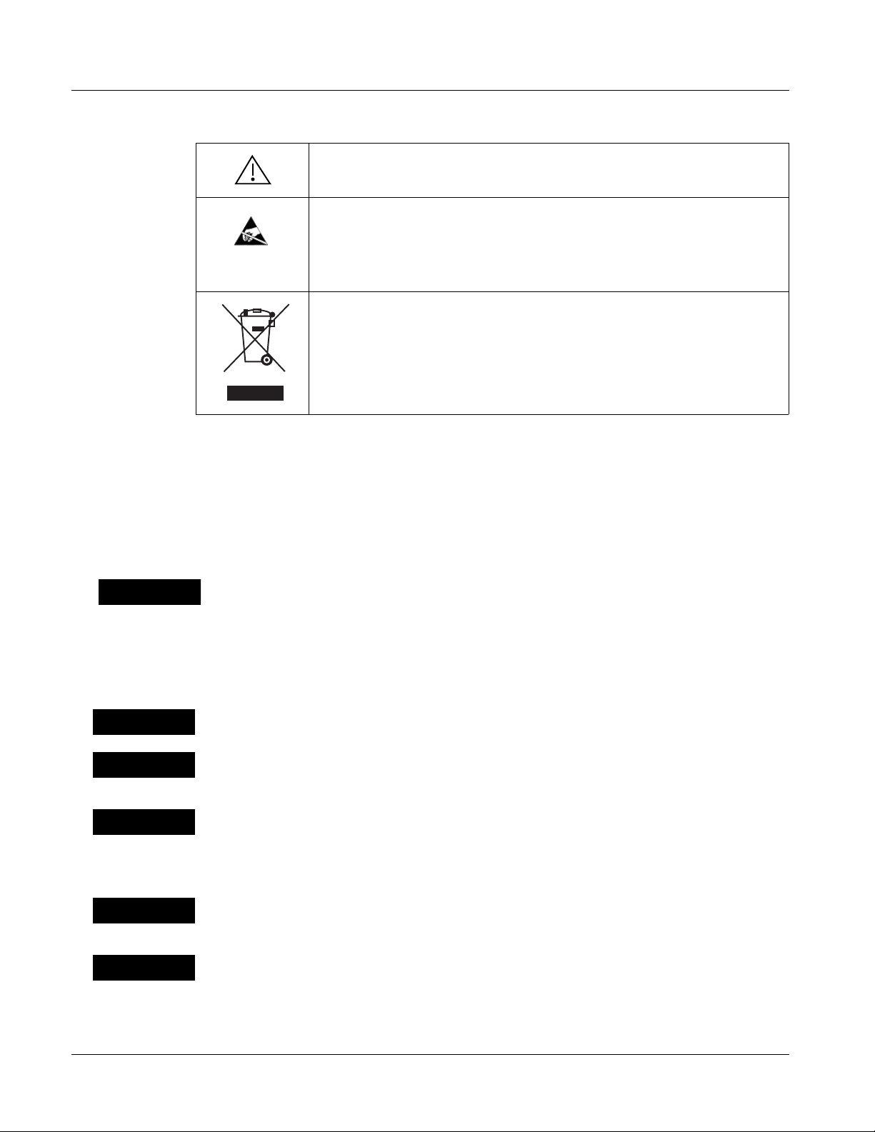
Labeling Symbol Definitions
Attention, consult accompanying documents.
Electronic device or assembly is susceptible to damage from an ESD
event. Han dle only using appropriate ESD prevention practices.
If ESD wrist strap is not available, handle card only by edges and avoid
contact with any connectors or components.
Symbol (WEEE 2002/96/EC)
For product disposal, ensure the following:
• Do not dispose of this product as unsorted municipal waste.
• Collect this product separately.
• Use collection and return systems available to you.
Safety Summary
Warnings
! WARNING !
Cautions
CAUTION
CAUTION
CAUTION
T o redu ce risk of electr ic shock do not remove line voltage service barrier cover on frame
equipment containing an AC power supply. NO USER SERVICEABLE PARTS INSIDE.
REFER SERVICING TO QUALIFIED SERVICE PERSONNEL.
This device is intended for environmentally controlled use only in appropriate video
terminal equipment operating environments.
This product is intended to be a component product of an openGear® frame. Refer to the
openGear frame Owner's Manual for important safety instructions regarding the proper
installation and safe operation of the frame as well as its component products.
Heat and power distribution requirements within a frame may dictate specific slot
placement of cards. Cards with many heat-producing components should be arranged to
avoid areas of excess heat build-up, particularly in frames using only convection cooling.
The 9085 has a moderate power dissipation (15 W max.). As such, avoiding placing the
card adjacent to other cards with similar dissipation values if possible.
CAUTION
CAUTION
1-4 9085 PRODUCT MANUAL 9085-OM (V4.3)
If required, make certain Rear I/O Module(s) is installed before installing the 9085 into the
frame slot. Damage to card and/or Rear I/O Module can occur if module installation is
attempted with card already installed in slot.
If card resists fully engaging in r ear I/O module mating connector, check for alignment and
proper insertion in slot tracks. Damage to card and/or rear I/O module may occur if
improper card insertion is attempted.
Page 9

Introduction 9085 Functional Description
9085 Functional Description
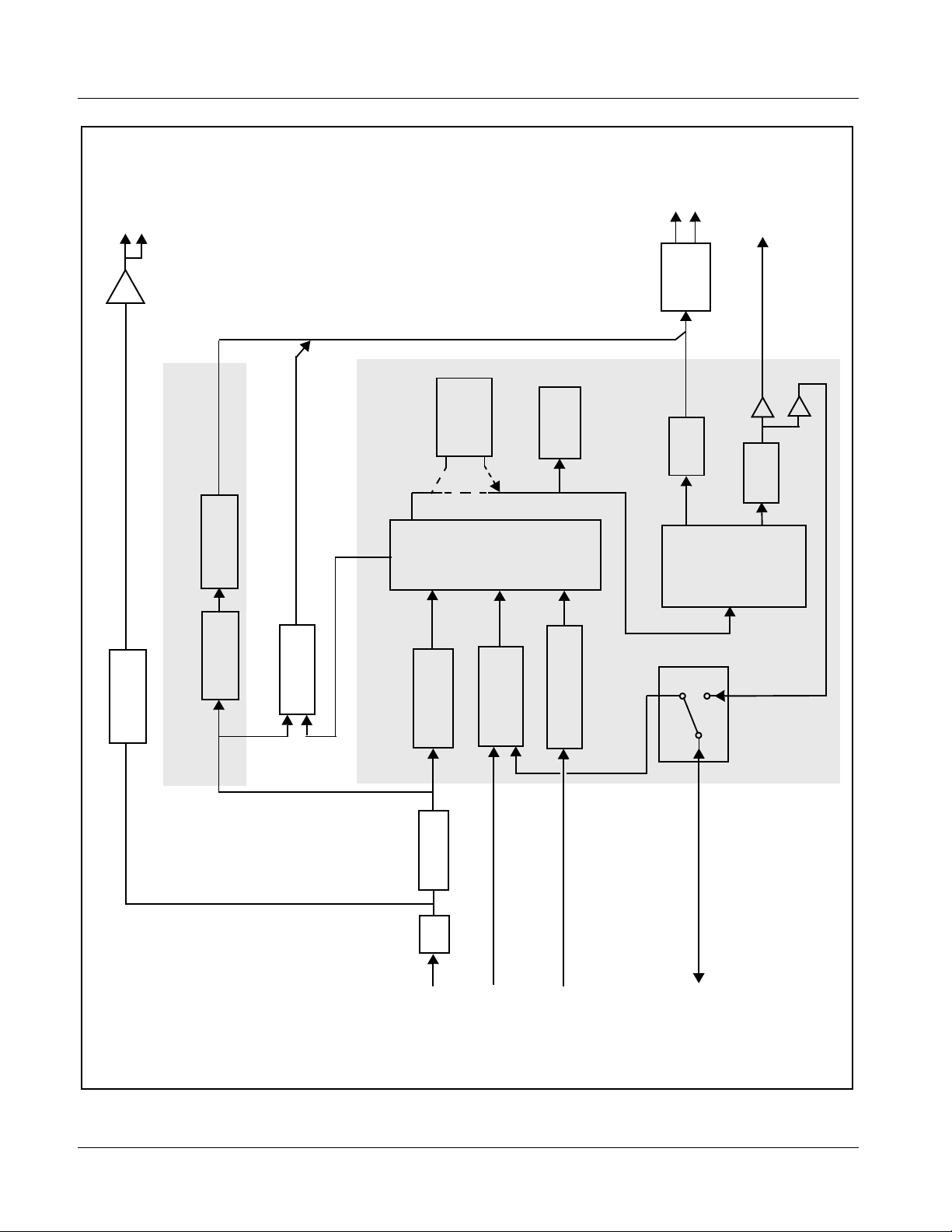
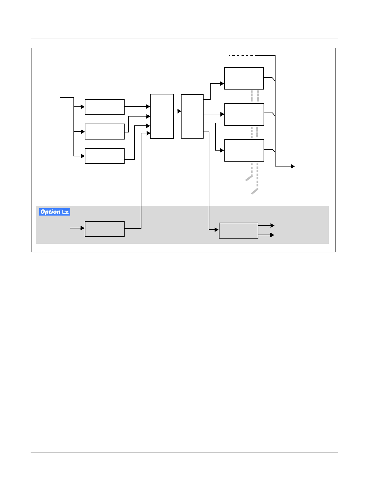
Figure 1-1 shows a functional block diagram of the 9085. The 9085 loudness
processor also includes a full 16-channel audio embedder/de-embedder, an
8-channel, and a 24-bit balanced analog-to-digital audio converter. The 9085
also handles AFD code detection/insertion.
Note: Some of the functions described below are available only when using the
9085 Input/Output Formats
Note: The input/output complement listed above represents the maximum capability
DashBoard™, or Cobalt
Panels use r int erf ace s. Re fer to User Con tro l Int erf ace ( p. 1- 14) for us er inter face descriptions.
®
OGCP-9000 or OGCP-9000/CC Remote Control
The 9085 provides the following inputs and outputs:
• Inputs:
• HD/SD SDI IN – dual-rate HD/SD-SDI input
• AES I/O (1-4) – user-switchable as AES inputs or AES outputs
• AES IN (5-8) – dedicated AES inputs
• AN-AUD IN (1-8) – balanced analog audio inputs
• Outputs:
• SDI OUT – two dual-rate HD/SD-SDI buffered video outputs
• RCK OUT – two reclocked HD/SD-SDI buffered input copies
• AES OUT (1-8) – dedicated AES outputs
• AES I/O (1-4) – user-switchable as AES inputs or AES outputs
of the 9085. The practical input/output complement is determined by the particular Rear I/O Module used with the 9085. Refer to 9085 Rear I/O Modules
(p. 1-16) for more information.
9085-OM (V4.3) 9085 PRODUCT MANUAL 1-5
Page 10
1 9085 Functional Description
AES OUT
(1-8)
AES
Encode
RCK OUT
depicts full input/output
Note: Signal connections shown
SDI OUT
capability. Practical input/
output signal availability is
determined by Rear I/O
Module used. Refer to
9085 Rear I/O Modules
(p. 1-16) for more
information.
LKFS
Loudness
Processor
Monitor
Serializer/
Cable
Drivers
Audio
Embed
AFD
Insert
Audio LTC
Vid Proc
Reclock
Video Functions
TC
Processing
Audio
De-Embed
Audio Proc e ssor
Deserialize
EQ
Gain
Audio
Routing/
Control
SRC
AES Decode/
Audio A/D
Differential Analog
S11–S14
[AES IN (1-4)]
Delay
Offset Adj.
Correction/
Audio-Video
[AES OUT (1 -4)]
IN (1-8)
AN-AUD
HD/SD SDI IN
AES IN (5-8)
AES I/O (1-4)
9085-BD V4.1
Figure 1-1 9085 Functional Block Diagram
1-6 9085 PRODUCT MANUAL 9085-OM (V4.3)
Page 11

Introduction 9085 Functional Description
Video Functions Description
Video Processor
The 9085 provides full color processing control (luma gain and lift, chroma
saturation, and color phase) of the output video.
AFD Inserter
This function provides for assignment and insertion of AFD codes into the
SDI output video. Using this function, AFD codes in accordance with the
standard 4-bit AFD code designations can be applied to the output video.
This function checks for any existing AFD code within the received video
input. If a code is present, the code is displayed. When used in conjunction
with a separate downstream card capable of providing AFD-directed scaling,
the image can in turn b e scaled in accord ance with th e AFD coding embedd ed
by this card.
The function also allows the selection/changing of the AFD code and
ancillary data line number for the outputted AFD code.
Timecode Processor
(See Figure 1-2.) This fun ct ion provi de s for ext rac ti on of time code data fro m
the input video, and in turn re-insertion of timecode data into the output SDI.
The function can monitor SDI video streams, and audio LTC over a selected
channel, for supported timecode formats and then se le ct and prioritize among
SDI VITC, SDI ATC_VITC, and SDI ATC_LTC timecode sources. If the
preferred format is detected, the preferred format is used by the card; if the
preferred format i s not det ected , the card us es ot her f ormats (where avail able)
as desired.
The function also provi des con ver sion be tween va rious timecod e fo rmats a nd
provides independent insertion and line number controls for each SDI
timecode output format.
Option +LTC allows bidirectional transfer and conversion
between VBI formats over SDI and audio LTC, as well as RS-485 LTC.
Audio LTC can be received or sent over a selected balanced analog audio
input, or as digital audio over a selected embedded or AES input.
9085-OM (V4.3) 9085 PRODUCT MANUAL 1-7
Page 12
1 9085 Functional Description
HD/SD–SDI
(From Video Proc)
SDI VITC
Timecode
Proc/Embed
SDI
Video
Input
SDI VITC
Detect/Extract
SDI ATC_VITC
Detect/Extract
SDI ATC_LTC
Detect/Extract
Priority/
Select
Buffer/
Format
ATC_VITC
Timecode
Proc/Embed
ATC_LTC
Timecode
Proc/Embed
HD/SD–SDI
Video Output
Insert
Control
Line
Number
Control
Audio/
RS-485 LTC
Audio LTC
Select/Extract
Audio Processor Description
Audio/RS-485
LTC Generate
Audio LTC Out
RS-485 LTC Out
Figure 1-2 Timecode Processor
The audio processor operates as an internal audio router. The router function
chooses from the foll owing inputs:
• 16 channels of embedded audio from the SDI video
• 16 channels (8 pairs) of discrete AES input
• 8 channels of balanced analog audio input
• Four independent internal tone generators (described below)
• Digital silence (mute) setting
• Internal Down Mix and Mono Mixer outputs (described below)
The router function provides the following audio outputs:
• 16 channels of embedded audio on the SDI output
• 16 channels of discrete AES output on eight discrete AES pairs
1-8 9085 PRODUCT MANUAL 9085-OM (V4.3)
Page 13
Introduction 9085 Functional Description
The router acts as a full audio cross point. Each of th e 24 out put channels (16
embedded, 16 discrete AES) can receive signal from any one of the 40 (16
embedded, 16 discrete AES, 8 analog) input channels, four internal tone
generators, or several mixer sources. Unused output channels can be mapped
to a “Silence” source. Each output also provides gain adjustment and
selectable polarity inversion.
Output audio rates are always 48 kHz, locked to output video, but discrete
AES inputs can be set to use sa mple rate converters to ali gn t hes e inputs with
the output timing. (AES must be nominally 48 kHz input; 32, 44.1, 96, and
192 kHz inputs are not compatib le with the 90 85.) The sample r ate conver ters
are disabled by default. Output AES is always precisely synchronized with
the output video. The balanc ed analog audio i nput is sampled at 48 kHz with a
+24 dBu clipping level (+24 dBu => 0 dBFS).
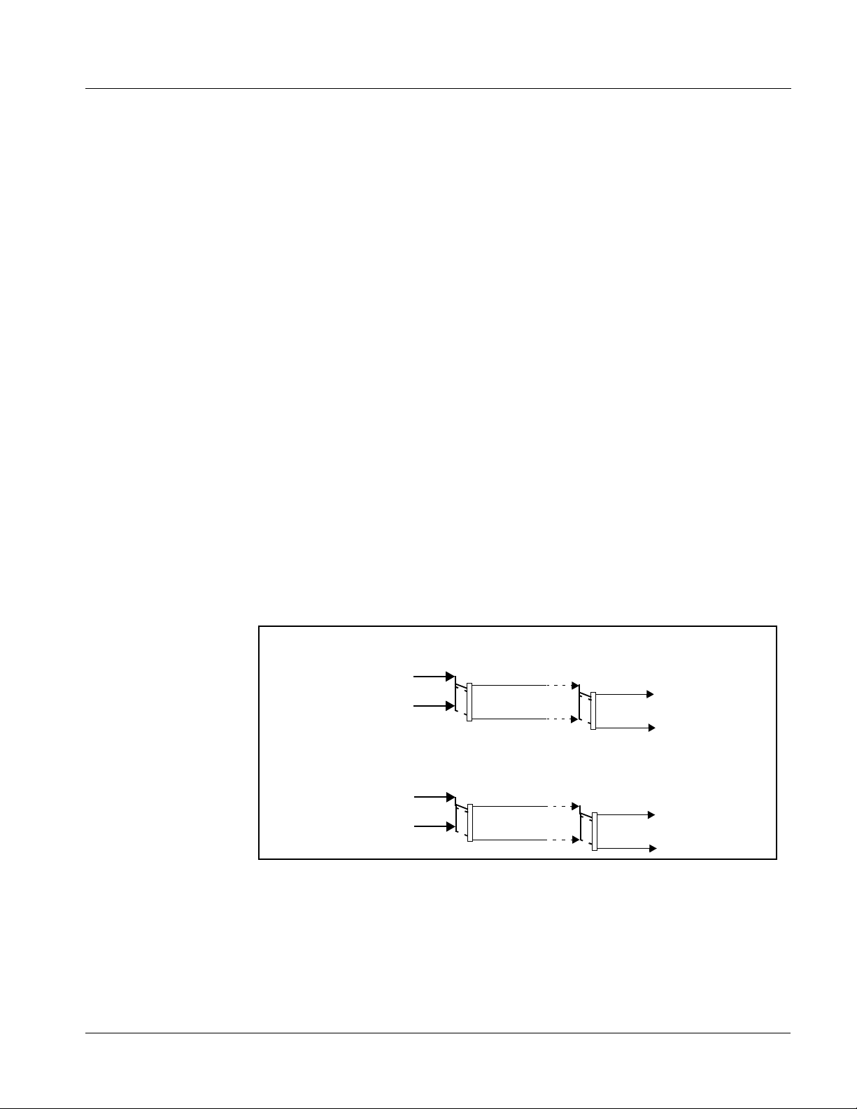
As set with the default settings, t he routing be tween embedded aud io channels
Embed Ch 1 thru Embed Ch 16 and discrete AES a udi o ch anne ls AES Ch1 thru
AES Ch 16 is as shown in Figure 1-3. In this mode, the routing is basic 1-to-1
embedding/de-embedding for the 16 embedded and AES discrete audio
channels. Other sources and/or destinations (described below) for each
channel are selected using the card edge controls or a remote control system.
As shown in Figure 1-1, the 9085 and 9085 are equipped with eight discrete
AES input pair ports and eight discrete AES output pair ports. On Rear I/O
Modules having limited AES I/O capabilities, switches S11 thru S14 allow
available rear module BNC connectors to be allotted between AES inputs and
outputs as desired. Buffered copies of
AES OUT (1-8) are available as
dedicated outputs and as respective outputs fed through S11 – S14 on the
card.
Embedded Audio
Group 1/2
AES Ch 1
AES Ch 8
AES Ch 9
AES Ch 16
Embed Ch 1
•
•
•
Embedded Audio
•
•
•
•
•
•
Embed Ch 8
Group 3/4
Embed Ch 9
•
•
•
Embed Ch 16
Figure 1-3 Default Embed/De-Embed Audio Routing
AES Audio Out
Pairs 1-4
AES Ch 1
•
•
•
AES Ch 8
AES Audio Out
Pairs 5-8
AES Ch 9
•
•
•
AES Ch 16
9085-OM (V4.3) 9085 PRODUCT MANUAL 1-9
Page 14
1 9085 Functional Description
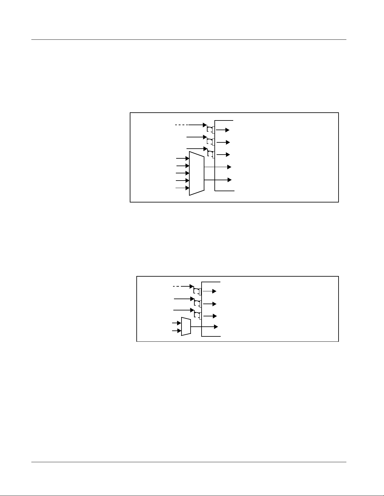
Audio Down Mixer and Mono Mixer Function
(See Figure 1-4.) The audi o down mixer funct ion provid es for the se lection of
any five embedded, AES discre te, or analog audio source s serving as Left (
Right (
signals to be mult iplexe d int o a s tereo pa ir ( Down Mix L eft (
Mix Right (
R), Center (C), Left Surround ( Ls), a nd Right Surroun d (Rs) indi vidual
DM-L) and Down
DM-R)). The resulting stereo pair DM-L and DM-R can in turn be
routed and processed just like any of the other au dio so urces des cribe d earli er.
Embed Ch 1 - Ch 16
AES Ch 1 - Ch 16
AN-AUD Ch 1- Ch 8
Embedded Ch 1
Embedded Ch 2
AES Ch 6
Embedded Ch 4
Embedded Ch 5
L
R
C
Ls
Rs
DM-L
DM-R
L),
Figure 1-4 Audio Down Mix Functional Block Diagram with Example Sources
The mono mixer function (Figure 1-5) generates an additional mono-mixed
channel from two selected embedded, AES discret e, or an al og input channels
serving as left and ri ght in puts. The res ulting mono mix ch annel
turn be routed and processe d just l ike any o f the oth er aud io source s descri bed
earlier.
Emb Ch 1 - Ch 16
AES Ch 1 - Ch 16
AN-AUD Ch 1- Ch 8
Emb Ch 12
Emb Ch 16
L
R
Figure 1-5 Audio Mono Mix Functional Block Diagram with Example Sources
DM-Mono
Σ
MONO can in
1-10 9085 PRODUCT MANUAL 9085-OM (V4.3)
Page 15
Introduction 9085 Functional Description
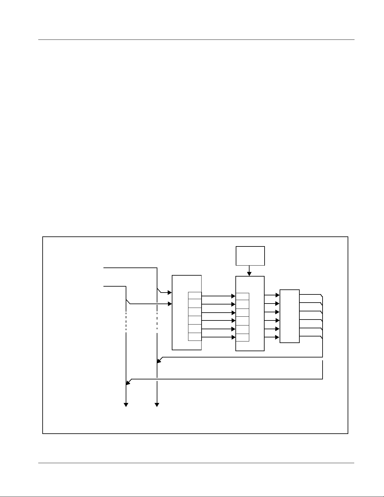
Loudness Processor Function
The loudness proces sor fu nction re ceives up to s ix sel ecte d ch annels from th e
Audio Routing/Gain Control function (which consists of routed output
destination channels Emb Out Ch 1 thru Ch 16, and AES Out Ch 1 thru Ch
16) and performs loudness processing on the selected channels. A loudness
processing profile best suited for the program material can be selected from
several loudness processing presets.
From Audio
Routing/Gain
Control
Emb Ch 1
– Ch 16
>
AES Ch 1
– Ch 16
>
9085-LP51 allows selected channels to be applied to the processor Left (
Right (
Right Surround (
have only Left (
R), Center (C), Low Frequency Effects (LFE), Left Surround (Ls), and
Rs) inputs. (9085-2LP20 and 9085-LP20 stereo processors
L), Right (R) inputs.) Whenever the loudness processor is
L),
active (selected by a us er control) , it overwrite s the up to si x selected cha nnels
with the new 5.1 loudness processed signals.
The example in Figure 1-6 shows routing of post-routing embedded output
channels Emb Out Ch 1 thru Ch 6 fed through the loudness processor. When
any of the card audio input channels are routed to any combination of
embedded or AES channel destinations, these channels in turn can be routed
through the loudness processor before being sent from the card. A master
output gain control is provided which allows fine adjustment of the overall
output level.
Processing
Preset
Select
Input/Output
Select
L
R
(C)
(LFE)
(Ls)
(Rs)
Emb Out Ch 1
Emb Out Ch 2
Emb Out Ch 3
Emb Out Ch 4
Emb Out Ch 5
Emb Out Ch 6
Loudness
Processing
L
R
(C)
(LFE)
(Ls)
(Rs)
Master
Output
Gain
Control
Selected channels Emb Ch 1 – Ch 6 are overwritten with the
loudness processed 5.1 content.
Note: 5.1-channel (9085-LP51) loudness
processor shown. Single stereo loudness
processor (9085-LP20) has only L and R
inputs/outputs. Dual Stereo Loudness
To AES Pair
1-8 Output
Ports
To Audio
Embed
Processor (9085-2LP20) has two
identical, independent stereo loudness
processors.
Figure 1-6 5.1-Channel Loudness Processor with Example Sources
9085-OM (V4.3) 9085 PRODUCT MANUAL 1-11
Page 16

1 9085 Functional Description
Audio/Video Delay Offset
The 9085 includes an audio/video delay offset function that allows audio/
video resyncing to compensate for an 8 msec delay induced by the loudness
processing function. I deal r esync of audio i s provi ded by adva ncing t he audi o
8 msec using this function.
Note: Although similar to a framesync function, the audio/video delay has significant
limitations (as compared to a full framesync function) which should be considered when setting up and using this function. These considerations, along
with the proper setup to use the 9085 audio/video delay function, are fully
described in Chapter 3. Operating Instructions.
Audio LKFS Monitor Description
Note: Refer to Appendix A, “Loudness Measurement Guidelines and Techniques”
for more information about LKFS parameters and this function, as well as
practical measurement techniques.
This function monitors selected output (“destination”) channels from the
Audio Routing/Gain Control function and applies signal analysis based on
ITU-R BS.1770-1 – ATSC A/85 criteria to produce an LKFS measurement
and provide indications of under-threshold and over-threshold level
conditions.
The function can monitor any combination of embedded, AES, or analog
channels selected as the L, R, C, Ls, and Rs I TU-R BS.1770-1 channels (note
that the LFE and AUX channels are not included in any LKFS calculations).
Because the LKFS monitor uses output (post-processed “destination”)
channels, LKFS values displayed are post-loudness processed values.
The functions pro vides a configura ble moving avera ge perio d for t ailorin g the
measurement to suit various program material conditions.
Tone Generator Function
The 9085 contains four built-in tone generators (Tone Generator 1 thru Tone
Generator 4). Each of the four tone generators can be set to a different
frequency, and are available as audio sources for the embedded or AES a udio
outputs.
18 discrete sine wave f requencies ar e available , ranging from 50 Hz to 1 6 kHz
(default frequency is 1.0 kHz).
1-12 9085 PRODUCT MANUAL 9085-OM (V4.3)
Page 17

Introduction 9085 Functional Description
AES Audio Input Advanced Features
AES Sample Rate Converter
The 9085 AES inputs have sample rate converters that can be independently
enabled for each AES pair to allow the card to interface with asynchronous
AES sources (sources in which AES timing does not match the video input
timing). The sample rate converters are set to disabled (bypassed) by default;
this is necessary when embedding undecoded, non-PCM data such as
®
Dolby
Dolby
AES or embedded audio signal, SRC is automatically bypassed along with
gain and polarity controls.
Zero-Delay Audio Embedding
In cases where additiona l delay must be avoided, it may be desirable to e mbed
AES with minimum latency. Using zero-delay embedding, the video can then
be delayed by one frame to account for any remaining audio delay. In this
manner, any delay between video and audio can be cleanly contained and
managed within one frame period.
E or Dolby® Digital™ audio streams. When a valid Dolby® E or
®
Digita l™ sign al ( in a ccord ance wit h SMPTE 337M ) is det ected on an
When zero-delay audio emb edding is en abled for a give n AES pair , th e pair is
directly embedded int o its corres ponding group (for example , AES Pair 1 in to
embedded channels 1 an d 2; AES Pai r 2 int o embedde d channe ls 3 an d 4, a nd
so on) with the normal audio sync delay being bypassed.
This function overrides the audio routing system (for example, if AES Pair 1
is selected then the cont rols to route AES Pair 1 int o other embedded cha nnels
will not apply). Gain and polarity control is not available when this option is
selected. Zero-delay audio embedding is set to Off by default.
Low-Latency AES Passthrough
This function is similar to zero-delay audio embedding. If low-latency AES
passthrough is selected for a given input pair, it causes the corresponding
AES output pair to act as a bit-for-bit copy of the corresponding AES input
pair.
This control overrides the normal audio routing and delay. Gain and polarity
control is not available when this option is selected. Passthrough is set to Off
by default.
Dolby Decoding Option (+DEC)
If your 9085 is equipped with Dolby® decoding as an option, refer to
supplement “Dolby Decoding Option (+DEC)” (PN DDO-MS) that was
shipped with this manual.
If you need a copy of this supplement, please contact us at the information
provided at the back of this chapter.
9085-OM (V4.3) 9085 PRODUCT MANUAL 1-13
Page 18
1 9085 Functional Description
User Control Interface
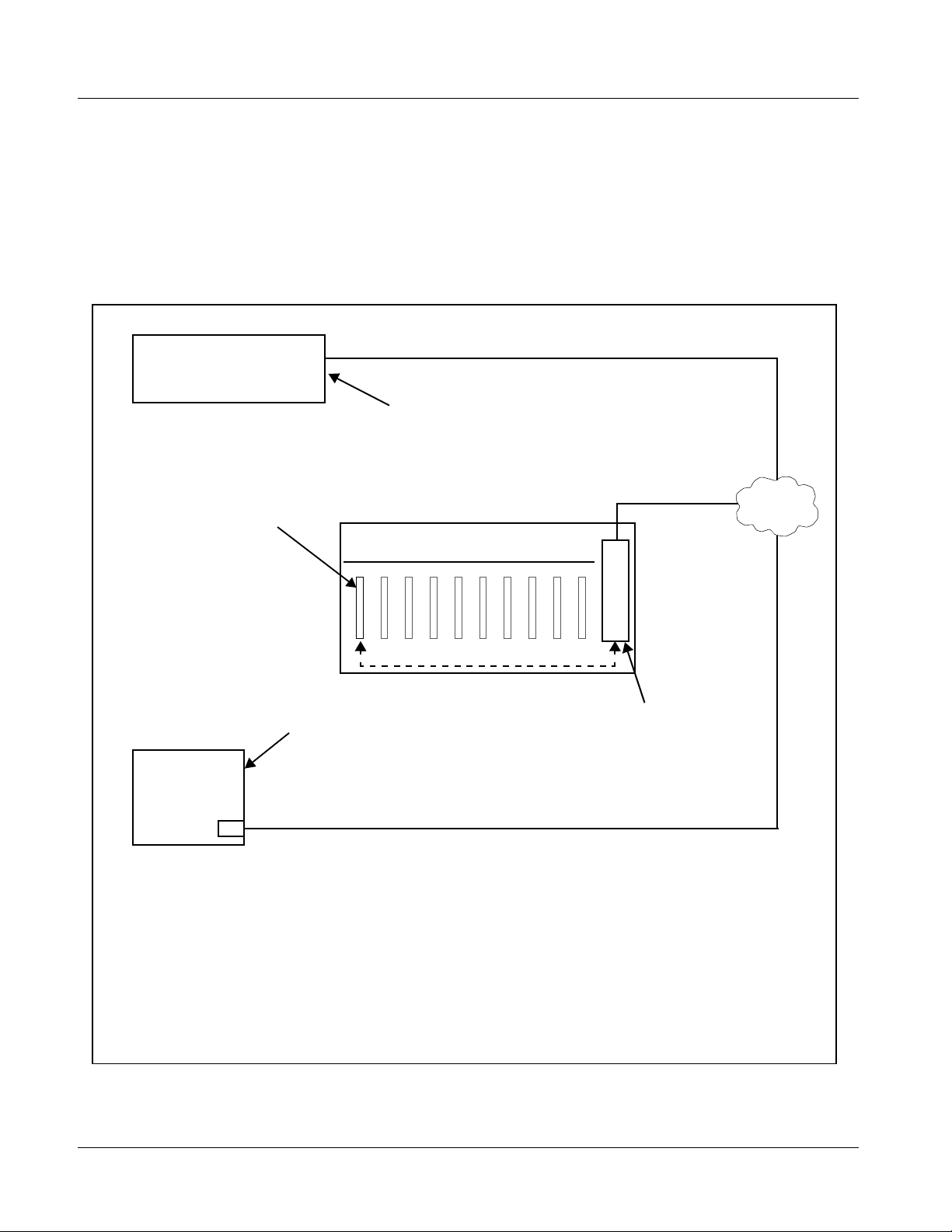
Figure 1-7 shows the user control interface options for the 9085. These
options are individually described below.
Note: All user control interfaces described here are cross-compatible and can oper-
ate together as desired. Where applicable, any control setting change made
using a particular user interface is reflected on any other connected interface.
OGCP-9000/CC Control Panel
OGCP-9000 Control Panel
Card Edge Controls
9085 card can be
controlled using built-in
card edge controls
Computer
with NIC
or
DashBoard™ Remote Control
Using a computer with
DashBoard™ installed, 9085
card can be remotely controlled
over a LAN
Remote Control Panel
Using the Control Panel,
9085 card can be remotely
controlled over a LAN
LAN
20-Slot-Frame with Network Controller
Card
In conjunction with a frame equipped
with a Network Controller Card, 9085
card can be remotely controlled over
a LAN
Note: • To communicate with DashBoard™ or a Cobalt® OGCP-9000/CC or OGCP-9000 Control Panel,
the frame must have the optional MFC-8320-N network controller card installed.
• DashBoard™ and the Remote Control Panels provide network control of the 9085 as shown. The
value displayed at any time on the card, or via DashBoard™ or a Control Panel is the actual value
as set on the card, with the current value displayed being the actual value as effected by the card.
Parameter changes made by any of these means are universally accepted by the card (for
example, a change made using the card controls will change the setting displayed on
DashBoard™ and a Control Panel; a change made using DashBoard™ will similarly change the
setting displayed on a Control Panel and the card itself).
Figure 1-7 9085 User Control Interface
1-14 9085 PRODUCT MANUAL 9085-OM (V4.3)
Page 19

Introduction 9085 Functional Description
• Built-in Card Edge User Interface – Using the built-in card edge
controls and display, card control settings can be set using a front
panel menu.
Note: Some of the 9085 functions described in this manual are available only when
using the DashBoard™, or Cobalt
Control Panels user interfaces.
• DashBoard™ User Interface – Using DashBoard™, the 9085 and
other cards installed in openGear®
®
OGCP-9000 or OGCP-9000/CC Remote
1
frames such as the Cobalt®
HPF-9000 or 8321-C Frame can be controlled from a computer and
monitor.
DashBoard™ allows users to view all frames on a network with
control and monitoring for all populated slots inside a frame. This
simplifies the setup and use of numerous modules in a large
installation and offers the ability to centralize monitoring. Cards
define thei r controllable parameters to DashBoard™, so the control
interface is always up to date.
Download the free DashBoard™ software by going to
www.cobaltdigital.com
and selecting “DashBoard Control and
Monitoring” on the home page. The DashBoard™ user interface is
described in Chapter 3,“Operating Instructions”.
Note: If network remote control is to be used for the frame and the frame has not yet
been set up for remote control, Cobalt
User Guide (PN 9000RCS-RM) provides thorough information and
step-by-step instructions for setting up network remote control of COMPASS
cards using DashBoard™. (Cobalt
Remote Control Panel product manuals have complete instructions for setting
up remote control using a Remote Control Panel.)
Download a copy of this guide by clicking on the Support>Documents>
Reference Guides link at www.cobaltdigital.com and then select DashBoard
Remote Control Setup Guide as a download, or contact Cobalt
Contact Cobalt Digital Inc. (p. 1-22).
®
reference guide Remote Control
®
OGCP-9000 and OGCP-9000/CC
®
as listed in
®
• Cobalt
®
OGCP-9000, OGCP-9000/CC and WinOGCP Remote
Control Panels – The OGCP-9000, OGCP-9000/CC, and W inOGCP
Remote Control Panels conveniently and intuitively provide
parameter monitor and control of the cards within the 20-slot frame.
The remote control panels allow quick and intuitive access to
hundreds of cards in a facility, and can monitor and allow adjustment
of multiple parameters at one time.
The remote contro l panels are totall y compatible with the op enGear
®
control software DashBoard™; any changes made with either system
are reflected on the oth er.
1. openGear® is a registered trademark of Ross Video Limited. DashBoard™ is a trademark of Ross
Video Limit e d .
9085-OM (V4.3) 9085 PRODUCT MANUAL 1-15
Page 20
1 9085 Functional Description
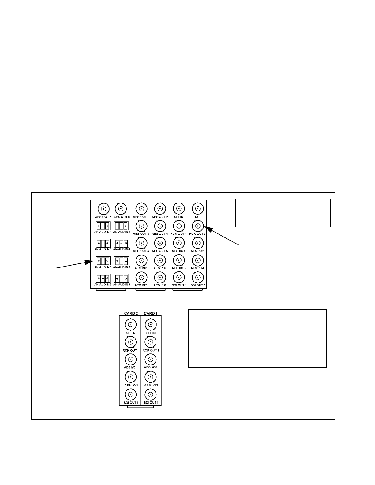
9085 Rear I/O Modules
The 9085 physically inter faces to sys tem video and audi o connectio ns using a
Rear I/O Module. Figure 1-8 shows a typical 9085 Rear I/O Module.
All inputs and outputs shown in the 9085 Functional Block Diagram (Figure
1-1) enter and exit the card via the card edge backplane connector. The Rear
I/O Module breaks out the 9085 card edge connections to industry standard
connections that interface with other components and systems in the signal
chain.
In this manner, the inputs and outputs requ ired for a pa rtic ular appli cati on can
be accommodated using a Rear I/O Module that best suits the requirements.
The required input and outputs are broken out to the industry standard
connectors on the Rear I/O Module; the unused inputs and outputs remain
unterminated and not available for use.
The full assortment of 9085 Rear I/O Modules is shown and described in
9085 Rear I/O Modules (p. 2-6) in Chapter 2, “Installation and Setup”.
Phoenix terminal
block connectors for
3-wire and 2-wire
terminations
Viewed from rear, the right column
of BNC connectors accommodates
the right-most card, with the left
column accommodating the
adjacent card to the left.
In this example with two 9085 cards
in slots 1 and 2, the right column
serves 9085, slot 1 and the left
column serves 9085, slot 2.
In this example, an RM-9085-G Rear I/O
Module provides a connection interface
for the signal types shown here.
BNC connectors for
coaxial video and
AES audio signals
Where a maximum of five BNC connections can suit
particular I/O requirements, a “split” Rear I/O Module offers
maximum card density within the frame by accommodating
two cards using a module occupying no more area than a
standard module. The RM-9085-A/S shown here
accommodates the signal complement shown for two
adjacent 9085 cards. (Split modules are identified by “/S” in
the part number.)
Figure 1-8 Typical 9085 Rear I/O Module
1-16 9085 PRODUCT MANUAL 9085-OM (V4.3)
Page 21

Introduction 9085 Functional Description
Audio and Video Formats Supported by the 9085
The 9085 supports all current SMPTE standard SD and HD video formats.
Table 1-1 lists and provides details regarding the audio and video formats
supported by the 9085.
Table 1-1 Supported Audio and Video Formats
Item Description/Specification
Input / Output Video Raster Structure: Frame Rate:
1080PsF 23.98; 24
1080p 23.98; 24
1080i
(1)
25; 29.97; 30
720p 23.98; 24; 25; 29.97; 30; 50; 59.94; 60
486i
575i
(1)
(1)
29.97
25
Embedded Audio The 9085 supports all four groups (16 channels) of embedded audio at
full 24-bit resolution in both SD (with extended data packets) and HD.
Analog Audio The 9085 supports 8 channels of balanced (differential) analog audio.
The analog audio is encoded such that a +24 dBu input is equivalent to
digital 0 dBFS.
Discrete AES Audio Input The 9085 can accept 16 channels (8 pairs) of discrete AES audio on
75Ω BNC connections. Sample rate conversion can be employed to
account for minor clock rate differences in the AES stream and the
input video stream.
Note: The AES signal must have a nominal rate of approximately
48 kHz. The 9085 does not support AES input at 32 kHz,
44.1 kHz, 96 kHz or 192 kHz rates.
Discrete AES Audio Output The 9085 can provide 16 channels (AES pairs 1 thru 8) of discrete AES
audio on 75Ω BNC connections.
(1) All rates displayed as frame rates; interlaced (“i”) field rates are two times the rate value shown.
9085-OM (V4.3) 9085 PRODUCT MANUAL 1-17
Page 22

1 Technical Specifications
Technical Specifications
Table 1-2 lists the technical specifications for the 9085 HD/SD Loudness
Processor with Audio-Video Delay Correction card.
Table 1-2 Technical Specifications
Item Characteristic
Part number, nomenclature • 9085-LP51 – 5.1-Channel Loudness Processor with Audio-Video
Delay Correction
• 9085-2LP20 – Dual Stereo Loudness Processor with
Audio-Video Delay Correction
• 9085-LP20 – Single Stereo Loudness Processor Loudness
Processor with Audio-Video Delay Correction
Installation/usage environment Intended for installation and usage in frame meeting openGear
modular system definition.
Power consumption < 15 Watts maximum
Environmental:
Operating temperature:
Relative humidity (operating or storage):
Frame communication 10/100 Mbps Ethernet with Auto-MDIX.
Indicators Card edge display and indicators as follows:
Controls Card edge switches as follows:
Internal Tone Generators Four built-in tone generators, each configurable for 18 discrete
32° – 104° F (0° – 40° C)
< 95%, non-condensing
• 4-character alphanumeric display
• Status/Error LED indicator
• Input Format LED indicator
• Menu Enter pushbutton switch
• Menu Exit pushbutton switch
• Up/down selection toggle switch
sine wave frequencies ranging from 50 Hz to 16 kHz.
Generator source signal level is equivalent to -20 dBu.
®
1-18 9085 PRODUCT MANUAL 9085-OM (V4.3)
Page 23

Introduction Technical Specifications
Table 1-2 Technical Specifica tions — continued
Item Characteristic
Serial Digital Video Input Data Rates Supported:
SMPTE 292 HD-SDI: 1.485 Gbps or 1.485/1.001 Gbps
SMPTE 259M-C SD-SDI: 270 Mbps
Impedance:
75 Ω terminating
Equalization (HD):
328 ft (100 m) Belden 1694A
Equalization (SD):
1000 ft (305 m) Belden 1694A
Return Loss:
> 15 dB at 5 MHz – 1.485 GHz
Serial Digital Video Outputs Number of Outputs:
Two processed HD/SD-SDI BNC per IEC 60169-8 Amendment 2
Two buffered reclocked input copies
Pre-Processor (Reclocked) Serial Digital
Video Outputs
Impedance:
75 Ω
Return Loss:
> 15 dB at 5 MHz – 270 MHz
> 12 dB at 270 MHz – 1.485 GHz
Signal Level:
800 mV ± 10%
DC Offset:
0 V ± 50 mV
Jitter (HD ):
< 0.15 UI (all outputs)
Jitter (SD ) :
< 0.10 UI (all outputs)
Overshoot:
< 0.2% of amplitude
Number of Outputs:
Two HD/SD-SDI BNC per IEC 60169-8 Amendment 2
Impedance:
75 Ω
9085-OM (V4.3) 9085 PRODUCT MANUAL 1-19
Page 24

1 Technical Specifications
Table 1-2 Technical Specifications — continued
Item Characteristic
AES Audio Input Standard:
SMPTE 276M
Number of Inputs (maximum):
8 unbalanced
Input Level:
0.1 to 2.5 Vp-p (5 Vp-p tolerant)
Input Impedance:
75 Ω
Return Loss:
> 12 dB at 100 kHz to 6 MHz
Resolution:
24-bit only
Sample Rate:
48 kHz
SRC:
32-channel; 142 dB S/N
AES Audio Output Standard:
SMPTE 276M
Number of Outputs (maximum):
8 unbalanced AES
Output Impedance:
75 Ω
Return Loss:
> 30 dB 100 kHz to 6 MHz
Sample Rate:
48 kHz
Analog Audio Input Number of Inputs (maximum):
Eight, 3-wire balanced analog audio using Phoenix connectors
with removable screw terminal blocks (Phoenix PN 1803581;
Cobalt PN 5000-0013-000R)
Sampling Rate:
48 kHz (locked to video input)
Signal Level:
+24 dBu => 0 dBFS
A/D Frequency Response:
20 – 20 kHz ± 0.25 dB
1-20 9085 PRODUCT MANUAL 9085-OM (V4.3)
Page 25

Introduction Warranty and Service Information
Warranty and Service Information
Cobalt Digital Inc. Limited Warranty
This product is warranted to be free from defects in material and workmanship for a period of five (5)
years from the date of shipment to the original purchaser, except that 4000, 5000, 6000, 8000 series
power supplies, and Dolby
material and workmanship for a period of one (1) year.
Cobalt Digital Inc.'s (“Cobalt”) sole obligation under this warranty sh all be limited to, at its option, (i)
the repair or (ii) replacement of the produc t, and the det ermination of whether a defect is covered under
this limited warranty shall be made at the sole discretion of Cobalt.
This limited warrant y appl ies on ly t o the origi nal end-pu rchaser of the produ ct, and i s not assign able o r
transferrable therefrom. This warr ant y i s li mited to defects in material and work ma nship, and shall not
apply to acts of God, accidents, or negligence on behalf of the purchaser, and shall be voided upon the
misuse, abuse, alteration, or modification of the product. Only Cobalt authorized factory
representatives are authorized to make repairs to the product, and any unauthorized attempt to repair
this product shall immediately void the warranty. Please contact Cobalt Technical Support for more
information.
®
modules (where applicable) are warranted to be free from defects in
To facilitate the resolut ion of warranty related issues, Cobalt recommends registering the product by
completing and returning a product registration form. In the event of a warrantable defect, the
purchaser shall notify Cobalt with a descripti on of t he p r oble m, an d Cobalt shall provide the pur ch aser
with a Re turn Mate rial Auth oriz ation (“RMA”). For retu rn, defective product s should be double boxed,
and sufficiently protecte d, in the original packa ging, or equivalent, a nd shipped to the Coba lt Factory
Service Center, postage prepaid and insured for the purchase price. The purchaser should include the
RMA number, description of the problem encountered, date purchased, name of dealer purchased
from, and serial number with the shipment.
Cobalt Digital Inc. Factory Service Center
2406 E. University Avenue Office: (217) 344-1243
Urbana, IL 61802 USA Fax: (217) 344-1245
www.cobaltdigital.com Email: info@cobaltdigital.com
THIS LIMITED WARRANTY IS EXPRESSLY IN LIEU OF ALL OTHER WARRANTIES
EXPRESSED OR IMPLIED, INCLUDING THE WARRANTIES OF MERCHANTABILITY AND
FITNESS FOR A PARTICULAR PURPOSE AND OF ALL OTHER OBLIGATIONS OR
LIABILITIES ON COBALT'S PART. ANY SOFTWARE PROVIDED WITH, OR FOR USE WITH,
THE PRODUCT IS PROVIDED “AS IS.” THE BUYER OF THE PRODUCT ACKNOWLEDGES
THAT NO OTHER REPRESENTATIONS WERE MADE OR RELIED UPON W ITH RESPECT TO
THE QUALITY AND FUNCTION OF THE GOODS HEREIN SOLD. COBALT PRODUCTS ARE
NOT AUTHORIZED FOR USE IN LIFE SUPPORT APPLICATIONS.
COBALT'S LIABILITY, WHET HER IN CONTRACT, TORT, WARRANTY, OR OTHERWISE, IS
LIMITED TO THE REPAIR OR REPLACEMENT, AT ITS OPTION, OF ANY DEFECTIV E
PRODUCT, AND SHALL IN NO EVENT INCLUDE SPECIAL, INDIRECT, INCIDENTAL, OR
CONSEQUENTIAL DAMAGES (INCLUDING LOST PROFITS), EVEN IF IT HAS BEEN
ADVISED OF THE POSSIBILITY OF SUCH DAMAGES.
9085-OM (V4.3) 9085 PRODUCT MANUAL 1-21
Page 26

1 Contact Cobalt Digital Inc.
Contact Cobalt Digital Inc.
Feel free to contact our thorough and professional suppo rt repr es entatives for
any of the following:
• Name and address of your local dealer
• Product information and pricing
• Technical support
• Upcoming trade show in formation
Phone: (217) 344-1243
Fax: (217) 344-1245
Web: www.cobaltdigital.com
General Information: info@cobaltdigital.com
Technical Support: support@cobaltdigital.com
1-22 9085 PRODUCT MANUAL 9085-OM (V4.3)
Page 27

Overview
Chapter 2
Chapter 2 Installation and Setup
This chapter contains the following information:
• Setting I/O Switches for AES I/O (1-4) Ports (p. 2-1)
• Installing the 9085 Into a Frame Slot (p. 2-2)
• Installing a Rear I/O Module (p. 2-4)
• Setting Up 9085 Network Remote Control (p. 2-1 1)
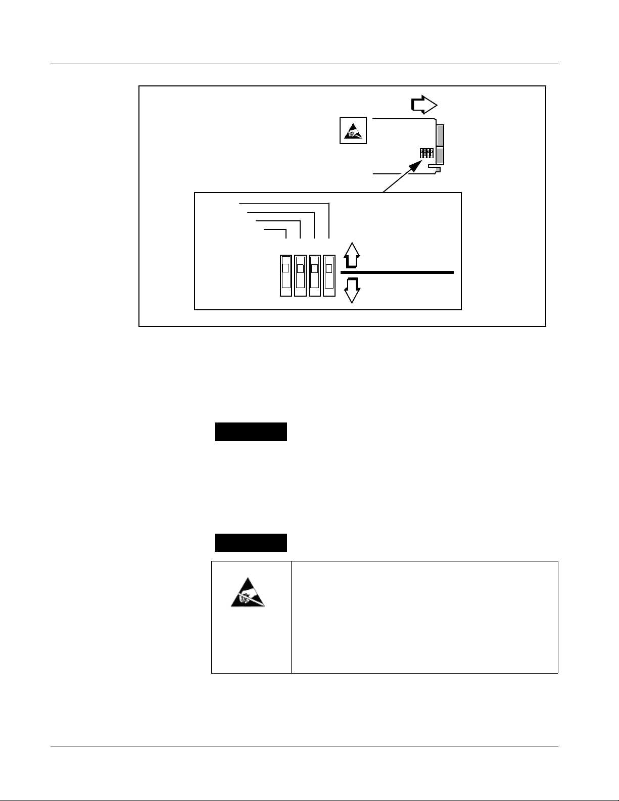
Setting I/O Switches for AES I/O (1-4) Ports
Note: This procedure is applicable only if any of the four AES I/O (1-4) ports on the
9085 are to be used as outputs (the switches are set to input mode by factory
default). The 9085 is equipped with a four-section red DIP switch that sets
AES pairs 1 thru 4 as either inputs or outputs. The factory default position is
the input position for each pair.
• If all of the AES I/O (1-4) ports are to be used as inputs (or not used at all),
omit this procedure.
• If any of the AES I/O (1-4) ports are to be used as outputs, set the switches
as described in this procedure.
Note switch S11 thru S14 settings for AES I/O 1 thru AES I/O 4 mode shown
in Figure 2-1. For p ort to be used as an output, set switch to down position as
shown in Figure 2-1.
Note: Regardless of S11 thru S14 settings for AES I/O 1 thru AES I/O 4, outputs
AES OUT (1-4) are still available on cards equipped with a Rear I/O Module
having dedicated AES OUT BNC connecto rs.
9085-O M (V4.3) 9085 PRODUCT MANUAL 2-1
Page 28
2 Installing the 9085 Into a Frame Slot
Rear of Card
AES I/O 4
AES I/O 3
AES I/O 2
AES I/O 1
S11S12S13S14
••••
Figure 2-1 9085 AES I/O (1-4) Mode Switches
Installing the 9085 Into a Frame Slot
CAUTION
Heat and power distribution requirements within a frame may dictate specific
slot placement of cards. Cards with many heat-producing components should
be arranged to avoid areas of excess heat build-up, particularly in frames
using only convection cooling. The 9085 has a moderate power dissipation
(15 W max.). As such, avoiding placing the card adjacent to other cards with
similar dissipation values if possible.
INPUT MODE
(Factory Default)
OUTPUT MODE
CAUTION
This device contains semiconductor devices which are
susceptible to serious damage from Electrostatic
Discharge (ESD). ESD damage may not be immediately
apparent and can affect the long-term reliability of the
device.
Avoid handling circuit boards in high static environments
such as carpeted areas, and when wearing synthetic fiber
clothing. Always use proper ESD handling precautions
and equipment when working on circuit boards and
related equipment.
2-2 9085 PRODUCT MANUAL 9085-OM (V4.3)
Page 29

Installation and Setup Installing the 9085 Into a Frame Slot
Note: If installing the 9085 in a slot with no rear I/O module, a Rear I/O Module is
required before cabling can be connected. Refer to Installing a Rear I/O Module (p. 2-4) for rear I/O module installation procedure.
CAUTION
If required, make certain Rear I/O Module(s) is installed before installing the
9085 into the frame slot. Damage to card and/or Rear I/O Module can occur if
module installation is attempted with card already installed in slot.
Note: Check the packaging in which the 9085 was shipped for any extra items such
as a Rear I/O Module connection label. In some cases, this label is shipped
with the card and should be installed on the Rear I/O connector bank corresponding to the slot location of the card.
Install the 9085 into a frame slot as follows:
1. Determine the slot in which the 9085 is to be installed.
2. Open the frame front access panel.
3. While holding the card by the card edges, align the card such that the
plastic ejector tab is on the bottom.
4. Align the card with the top and bottom guides of the slot in which the
card is being installed.
5. Gradually slide the card into the slot. When resistance is noticed, gently
continue pushing the card until its rear printed circuit edge terminals
engage fully into the rear I/O module mating connector.
CAUTION
If card resists fully engaging in rear I/O module mating connector, check for
alignment and proper insertion in slot tracks. Damage to card and/or rear I/O
module may occur if improper card insertion is attempted.
Verify that the card is fully engaged in rear I/O module mating connector.
6.
7. Close the frame front access panel.
8. Connect the input and output cables as follows:
• If the 9085 is being installed in a PN 8310-BNC or 8310-C-BNC
frame, refer to the label on the connector bank corresponding to the
card’s slot location for connector designations.
• If the 9085 is being installed in a frame using a specific 9085 Rear
I/O Module, connect cabling in accordance with the appropriate
diagram shown in Table 2-1, “9085 Rear I/O Modules” (p. 2-6).
9. Repeat steps 1 through 8 for other 9085 cards.
9085-OM (V4.3) 9085 PRODUCT MANUAL 2-3
Page 30

2 Installing a Rear I/O Module
Note: The 9085 BNC inputs are internally 75-ohm terminated. It is not necessary to
terminate unused BNC inputs or outputs.
Note: External frame sync reference signals are received by the card over a refer-
ence bus on the card frame, and not on any card rear I/O module connectors.
The frame has BNC connectors labeled REF 1 and REF 2 which receive the
reference signal from an external source such as a house distribution.
Note: To remove a card, press down on the ejector tab to unseat the card from the
rear I/O module mating connector. Evenly draw the card from its slot.
10. If network rem ote control is to be used for the fram e and the frame has
not yet been set up for remote control, perform setup in accordance with
®
Cobalt
9000RCS-RM)”.
Note: If installing a card in a frame already equipped for, and connected to
DashBoard™, no network setup is required for the card. The card will be discovered by DashBo ard™ and be ready for use.
reference guide “COMPASS™ Remote Control User Guide (PN
Installing a Rear I/O Module
Note: This procedure is applicable only if a Rear I/O Module is not currently
installed in the slot where the 9085 is to be installed.
The full assortment of 9085 Rear I/O Modules is shown and described in
9085 Rear I/O Modules (p. 2-6). Install a Rear I/O Module as follows:
1. On the frame, determine the slot in which the 9085 is to be installed.
2. In the mounting area corresponding to the slot location, install
Rear I/O Module as shown in Figure 2-2.
2-4 9085 PRODUCT MANUAL 9085-OM (V4.3)
Page 31

Installation and Setup Installing a Rear I/O Module
Align and engage mounting tab on Rear
I/O Module with the module seating slot
1
on rear of frame chassis.
DSCN3483A.JPG
Hold top of Rear I/O Module flush against
frame chassis and start the captive screw.
2
Lightly tighten captive screw.
Note: Rear I/O Modules RM-9085-C and -H occupy two rear
module slot mounting locations and use two captive screws.
Rear I/O Module RM-9085-G occupies three rear module
slot mounting locations and uses three captive screws.
DSCN3487A.JPG
Figure 2-2 Rear I/O Module Installation
9085-OM (V4.3) 9085 PRODUCT MANUAL 2-5
Page 32

2 Installing a Rear I/O Module
9085 Rear I/O Modules
Table 2-1 shows and describes the full assortment of Rear I/O Modules
specifically for use with the 9085.
Note: • Rear I/O Modules equipped with 3-wire Phoenix connectors are supplied
with removable screw terminal block adapters. For clarity, the adapters are
omitted in the drawings below.
• Rear I/O Modules with DOLBY META port provide RS-485 port usable for
Dolby metadata decoder output (where equipped with option +DEC) or serial
LTC I/O (where licensed for option +LTC).
Table 2-1 9085 Rear I/O Modules
9085 Rear I/O Module Description
RM-9085-A Provides the following conne cti on s:
• HD/SD-SDI coaxial input (SDI IN)
• Two HD/SD-SDI reclocked input copies
(RCK OUT)
• Four AES I/O coaxial input/outputs (AES I/O 1 thru
AES I/O 4; I/O function of each connection is
user-configurable)
• Two buffered SDI coaxial outputs (SDI OUT)
RM20-9085-A/S Split Rear Module. Provides each of the following
connections for two 9085 cards:
• HD/SD-SDI coaxial input (SDI IN)
• HD/SD-SDI reclocked input copy (RCK OUT)
• Two AES I/O coaxial input/outputs (AES I/O 1 and
AES I/O 2; I/O function of each connection is
user-configurable)
• Buffered SDI coaxial output (SDI OUT)
Note: For AES I/O 1 and AES I/O 2 on
RM20-9085-A/S Rear I/O Module to function
as inputs, AES I/O switches S11 – S12 must
be set to Input (factory default).
See Setting I/O Switches for AES I/O (1-4)
Ports (p. 2-1) for more information.
2-6 9085 PRODUCT MANUAL 9085-OM (V4.3)
Page 33

Installation and Setup Installing a Rear I/O Module
Table 2-1 9085 Rear I/O Modules — continued
9085 Rear I/O Module Description
RM-9085-B Provides the following connections:
• HD/SD-SDI coaxial input (SDI IN)
• Six analog balanced audio inputs (AN-AUD IN 1
thru AN-AUD IN 6)
• Two buffered SDI coaxial outputs (SDI OUT)
RM-9085-C
Provides the following connections:
• HD/SD-SDI coaxial input (SDI IN)
• Four AES I/O coaxial input/outputs (AES I/O 1 thru
AES I/O 4; I/O function of each connection is
user-configurable)
• Two dedicated AES coaxial audio inputs (AES IN 5
and AES IN 6)
• Two dedicated AES coaxial audio outputs
(AES OUT 1 and AES OUT 2)
• Eight analog balanced audio inputs (AN-AUD IN 1
thru AN-AUD IN 8)
• Two buffered SDI coaxial outputs (SDI OUT)
Note: For AES I/O 1 and AES I/O 2 on
RM20-9085-C Rear I/O Module to function as
inputs, AES I/O switches S11 – S12 must be
set to Input (factory default).
See Setting I/O Switches for AES I/O (1-4)
Ports (p. 2-1) for mo re information.
Note: AES OUT 1 and AES OUT 2 on RM-9085-C
Rear I/O Module always function as outputs
regardless of whether AES I/O 1 or
AES I/O 2 are used as inputs or outputs.
9085-OM (V4.3) 9085 PRODUCT MANUAL 2-7
Page 34

2 Installing a Rear I/O Module
Table 2-1 9085 Rear I/O Modules — continued
9085 Rear I/O Module Description
RM20-9085-D
Provides the following conne cti on s:
• HD/SD-SDI coaxial input (SDI IN)
• Four AES I/O coaxial input/outputs (AES I/O 1 thru
AES I/O 4; I/O function of each connection is
user-configurable)
• Two dedicated AES coaxial audio outputs
(AES OUT 1 and AES OUT 2)
• Eight analog balanced audio inputs (AN-AUD IN 1
thru AN-AUD IN 8)
• RS-485 LTC / Metadata I/O Port
• Two buffered SDI coaxial outputs (SDI OUT)
Note: For AES I/O 1 thru AES I/O 4 on
RM20-9085-D Rear I/O Module to function as
inputs, AES I/O switches S11 – S14 must be
set to Input (factory default).
See Setting I/O Switches for AES I/O (1-4)
Ports (p. 2-1) for more information.
Note: AES OUT 1 and AES OUT 2 on
RM20-9085-D Rear I/O Module always
function as outputs regardless of whether
AES I/O 1 or AES I/O 2 are used as inputs or
outputs.
RM20-9085-E
Provides the following conne cti on s:
• HD/SD-SDI coaxial input (SDI IN)
• Four AES I/O coaxial input/outputs (AES I/O 1 thru
AES I/O 4; I/O function of each connection is
user-configurable)
• Three dedicated AES coaxial audio inputs
(AES IN 5, AES IN 6, AES IN 8)
• Eight dedicated AES coaxial audio outputs
(AES OUT 1 thru AES OUT 8)
• RS-485 LTC / Metadata I/O Port
• Two buffered SDI coaxial outputs (SDI OUT)
Note: For AES I/O 1 thru AES I/O 4 on
RM20-9085-E Rear I/O Module to function as
inputs, AES I/O switches S11 – S14 must be
set to Input (factory default).
See Setting I/O Switches for AES I/O (1-4)
Ports (p. 2-1) for more information.
Note: AES OUT 1 thru AES OUT 4 on
RM20-9085-E Rear I/O Module always
function as outputs regardless of whether
AES I/O 1 thru AES I/O 4 are used as inputs
or outputs.
2-8 9085 PRODUCT MANUAL 9085-OM (V4.3)
Page 35

Installation and Setup Installing a Rear I/O Module
Table 2-1 9085 Rear I/O Modules — continued
9085 Rear I/O Module Description
RM-9085-F Provides the following connections:
• HD/SD-SDI coaxial input (SDI IN)
• Five AES coaxial inputs (AES IN 1 thru AES IN 4;
AES IN 8)
• Two dedicated AES coaxial audio outputs
(AES OUT 1 and AES OUT 2)
• Two buffered SDI coaxial outputs (SDI OUT)
Note: For AES IN 1 thru AES IN 4 on RM-9085-F
Rear I/O Module to function as inputs, AES I/O
switches S11 – S14 must be set to Input
(factory default).
See Setting I/O Switches for AES I/O (1-4)
Ports (p. 2-1) for more information.
RM-9085-G
Provides the following connections:
• HD/SD-SDI coaxial input (SDI IN)
• Two HD/SD-SDI reclocked input copies
(RCK OUT)
• Four AES I/O coaxial input/outputs (AES I/O 1 thru
AES I/O 4; I/O function of each connection is
user-configurable)
• Four dedicated AES coaxial audio inputs
(AES IN 5 thru AES IN 8)
• Eight dedicated AES coaxial audio outputs
(AES OUT 1 thru AES OUT 8)
• Eight analog balanced audio inputs (AN-AUD IN 1
thru AN-AUD IN 8)
• Two buffered SDI coaxial outputs (SDI OUT)
Note: For AES I/O 1 thru AES I/O 4 on RM-9085-G
Rear I/O Module to function as inputs, AES I/O
switches S11 – S14 must be set to Input
(factory default).
See Setting I/O Switches for AES I/O (1-4)
Ports (p. 2-1) for more information.
9085-OM (V4.3) 9085 PRODUCT MANUAL 2-9
Page 36

2 Installing a Rear I/O Module
Table 2-1 9085 Rear I/O Modules — continued
9085 Rear I/O Module Description
Provides the following conne cti on s:
• HD/SD-SDI coaxial input (SDI IN)
• Four dedicated AES coaxial audio inputs
RM-9085-H
(AES IN 5 thru AES IN 8)
• Eight dedicated AES coaxial audio outputs
(AES OUT 1 thru AES OUT 8)
• Four AES I/O coaxial input/outputs (AES I/O 1 thru
AES I/O 4; I/O function of each connection is
user-configurable)
• Two buffered SDI coaxial outputs (SDI OUT)
Note: For AES I/O 1 thru AES I/O 4 on
RM20-9085-H Rear I/O Module to function as
inputs, AES I/O switches S11 – S14 must be
set to Input (factory default).
See Setting I/O Switches for AES I/O (1-4)
Ports (p. 2-1) for more information.
Note: AES OUT 1 thru AES OUT 4 on RM-9085-H
Rear I/O Module always function as outputs
regardless of whether AES I/O 1 thru
AES I/O 4 are used as inputs or outputs.
RM-9085-J P rov id es the fol lowi ng conne cti on s:
• HD/SD-SDI coaxial input (SDI IN)
• Two HD/SD-SDI reclocked input copies
(RCK OUT)
• Four AES I/O coaxial input/outputs (AES I/O 1 thru
AES I/O 4; I/O function of each connection is
user-configurable)
• RS-485 LTC / Metadata I/O Port
• Two buffered SDI coaxial outputs (SDI OUT)
Note: For AES I/O 1 thru AES I/O 4 on RM-9085-J
Rear I/O Module to function as inputs, AES I/O
switches S11 – S14 must be set to Input
(factory default).
See Setting I/O Switches for AES I/O (1-4)
Ports (p. 2-1) for more information.
2-10 9085 PRODUCT MANUAL 9085-OM (V4.3)
Page 37

Installation and Setup Setting Up 9085 Network Remote Control
Table 2-1 9085 Rear I/O Modules — continued
9085 Rear I/O Module Description
RM20-9085-E-DIN-HDBNC High-density rear modules provides the following
connections:
• HD/SD-SDI coaxial input (SDI IN)
• Eight AES coaxial inputs (AES IN 1 thru AES IN 8)
• Eight AES coaxial outputs (AES OUT 1 thru
AES OUT 8)
• One HD/SD-SDI reclocked input copy
(RCK OUT 1)
• Two buffered SDI coaxial outputs (SDI OUT)
Note: Available equipped with High-Density BNC
(HDBNC) or DIN1.0/2.3 connectors as:
RM20-9085-E-HDBNC or RM20-9085-E-DIN,
respectively.
Setting Up 9085 Network Remote Control
Perform remote control setup in accordance with Cobalt® reference guide
“Remote Control User Guide (PN 9000RCS-RM)”.
Note: • If network remote contr ol is to be used for the frame and the frame has not
yet been set up for remote control, Cobalt
Control User Guide (PN 9000RCS-RM) provides thorough information and
step-by-step instructions for setting up network remote control of
COMPASS™ cards u sing Das hB oard ™. (Cobalt
OGCP-9000/CC Remote Control Panel product manuals have complete
instructions for setting up remote control using a Remote Control Panel.)
Download a copy of this guide by clicking on the
Support>Documents>Reference Guides link at www.cobaltdigital.com
and then select DashBoard Remote Control Setup Guide as a download, or
contact Cobalt
®
as listed in Contact Cobalt Digital Inc. (p. 1-22).
• If installing a card in a frame already equipped for, and connected to
DashBoard™, no network setup is required for the card. The card will be discovered by DashBoard™ and be ready for use.
9085-OM (V4.3) 9085 PRODUCT MANUAL 2-11
®
reference guide Remote
®
OGCP-9000 and
Page 38

This page intentionally blank
2-12 9085 PRODUCT MANUAL 9085-OM (V4.3)
Page 39

Overview
Chapter 3
Chapter 3 Operating Instructions
This chapter contains the following information:
If you are already familiar
with using DashBoard or a
Cobalt Remote Control
Panel to control Cobalt
cards, please skip to 9085
Function Submenu Li st and
Descriptions (p. 3-9).
• Control and Display Descriptions (p. 3-1)
• Accessing the 9085 Card via Remote Control (p. 3-5)
• Checking 9085 Card Information (p. 3-7)
• Ancillary Data Line Number Locations and Ranges (p. 3-8)
• 9085 Function Submenu List and Descriptions (p. 3-9)
• Example Setups Using The 9085 and DashBoard™ (p. 3-43)
• Troubleshooting (p. 3-46)
Control and Display Descriptions
This secti on describes the user interface controls, indicators, and displays for
using the 9085 card. The 9085 function s can be acces sed and contr olle d using
any of the user interfaces described here.
The format in which the 9085 functional controls, indicators, and displays
appear and are used varies depending on the user interface being used.
Regardless of the user interface being used, access to the 9085 functions (and
the controls, ind icato rs, an d disp lays r elat ed to a particul ar f uncti on) fo llows a
general arrangement of Function Submenus under which related controls can
be accessed (as described in Function Submenu/Parameter Submenu
Overview below).
Note: DashBoard™ and the Remote Control Panel provide greatly simplified user
interfaces as compared to using the card edge controls. For this reason, it is
strongly recommended that DashBoard™ or a Remote Control Panel be
used for all card applications other than the most basic cases. Card edge
control codes are not included in this manual. If card-edge control is to be
used, obtain a copy of “Manual Supplement – Card-Edge Control Reference
Master List and Instructions for Using Compass
Codes” (989CEC-MS.pdf) at
www.cobaltdigital.com>Support>Documents>Reference Guides.
9085-O M (V4.3) 9085 PRODUCT MANUAL 3-1
®
Card-edge (Local) Control
Page 40

3 Control and Display Descriptions
Note: When a setting is changed, settings displayed on DashBoard™ (or a Remote
Control Panel) are the settings as effected by the 9085 card itself and
reported back to the remote control; the value displayed at any time is the
actual value as set on the card.
Function Submenu/Parameter Submenu Overview
The functions and related pa rameters avai lable on the 9085 car d are organ ized
into function submenus, which consist of parameter groups as shown below.
Figure 3-1 shows how the 9085 card an d its submenus ar e orga nized, and also
provides an overview of how navig ation is performed be tween cards, func tion
submenus, and parameters.
If using DashBoard™ or a Remote Control Panel, the
desired 9085 card is first selected.
9085
Submenu a Submenu b
Individual Parameters
Each submenu consists of groups of parameters
related to the function submenu. Using the “Video
Proc” function submenu example, the individual
parameters for this function consist of various v ideo
processor parameters such as Luma Gain, Saturation,
and so on.
Figure 3-1 Function Submenu/Parameter Submenu Overvie w
• • •
The desired function submenu is next
selected.
Function Submenus consist of parameter
groups related to a particular 9085 card
function (for example, “Video Proc”).
Submenu z
3-2 9085 PRODUCT MANUAL 9085-OM (V4.3)
Page 41

Operating Instructions Control and Display Descriptions
DashBoard™ User Interface
(See Figure 3-2.) Th e 9085 fu nction submenus are or gani zed i n DashBoa rd™
using tabs. When a tab is selected, each parametric control or selection list
item associated with the function is displayed. Scalar (numeric) parametric
values can then be adjusted as desired using the GUI slider controls. Items in
a list can then be selected using GUI drop-down lists. (In this manner, the
setting effected using controls and selection lists displayed in DashBoard™
are comparable to the su bmenu ite ms access ed and commi tted using the 9085
card edge c ontrols.)
Typical On/Off
Control
Typical Parametric
Control
Typical Selection
List
DashBoard Tabs
Figure 3-2 Typical DashBoard™ Tabs and Controls
9085-OM (V4.3) 9085 PRODUCT MANUAL 3-3
Page 42

3 Control and Display Descriptions
Cobalt® Remote Control Panel User Interfaces
(See Figure 3-3.) Similar to the function submenu tabs using DashBoard™,
the OGCP-9000 (and OGCP-9000/CC) Remote Control Panels have a Select
Submenu key that is used to display a list of function submenus. From this
list, a control knob on the Control Panel is used to select a function from the
list of displayed function submenu items.
When the desired function submenu is selected, each parametric control or
selection list item associated with the function is displayed. Scalar (numeric)
parametric values can then be adjusted as desired using the control knobs,
which act like a potentiometer. Items in a list can then be selected using the
control knobs which cor respo ndingl y act li ke a r otary switch . (In t his man ner,
the setting effected using co ntr ols and selection lists displayed on t h e Co ntr ol
Panel are comparable to t he submenu i tems acce ssed and committed u sing the
9085 card edge controls.)
Figure 3-3 shows accessing a function submenu and its parameters (in this
example, “Embedded Audio Output Group 1/2”) using the Control Panel as
compared to using the card edge controls.
Embedded Audio Group 1/2
function (among others) is
accessed using the Control
Panel Select Submenu key.
Embedded Audio Group 1/2
function is selected from the
list of functions (submenu
items) using any knob
When the Embedded Audio
Group 1/2 function submenu
is selected, its related
parameters are now
displayed.
In this example, Gain for
Embedded Channel 1 is
adjusted using the
corresponding Gain control
knob.
Note: Refer to “OGCP-9000 Remote Control Panel User Manual” (PN
OGCP-9000-OM) or “OGCP-9000/CC Remote Control Panel User Manual”
(PN OGCP-9000/CC-OM) for complete instructions on using the Control
Panels.
9305_CP2A.PNG
Ch 1 Gain
20.0 dB
Ch 3 Gain
0.0 dB
Ch 2 Gain
0.0 dB
Ch 1 Gain
0.0 dB
OGCP_GEN.JPG
Figure 3-3 Control Panel Setup of Example Audio Control Function Setup
3-4 9085 PRODUCT MANUAL 9085-OM (V4.3)
Page 43

Operating Instructions Accessing the 9085 Card via Remote Control
Accessing the 9085 Card via Remote Control
Access the 9085 card using DashBoard™ or Cobalt® Remote Control Panel
as described below.
Accessing the 9085 Card Using DashBoard™
1. On the computer connected to the frame LAN, open DashBoard™.
2. As shown belo w, in the left side Basic View Tree locate t he Network
Controller Card associated with the frame containing the 9085 card to be
accessed (in this example, “MFC-8320-N SN: 00108053”).
DB_ACCESS1.PNG
3. As shown below, expand the tree to access the cards within the frame.
Click on the card to be accessed (in this example,
“Slot 7: CDI-9085-LP51”).
.
9085_DB_ACCESS2A.PNG
As shown on the next page, when the card is accessed in DashBoard™
its function submenu scree n showing ta bs for eac h functi on is disp layed.
(The particular submenu screen displayed is the previously displayed
screen from the last time the card was accessed by DashBoard™).
9085-OM (V4.3) 9085 PRODUCT MANUAL 3-5
Page 44

3 Accessing the 9085 Card via Remote Control
Card Access/Navigation
Tree Pane
Card Info
Pane
Card Function Submenu
and Controls Pane
Accessing the 9085 Card Using a Cobalt® Remote Control Panel
Press the Select Device key and select a card as shown i n the example bel ow.
9085_3366_3392.JPG
This display shows the list
order number of the device that
is ready for selection
This display shows the devices assigned to the Control Panel.
• Rotate any knob to select from the list of devices. The device selected using a knob
is displayed with a reversed background (in this example, “1 9085 - Post 1A
Loudness Processing”).
• Directly enter a device by entering its list number using the numeric keypad, and
then pressing Enter or pressing in any knob).
9085_DB_ACCESS3A3.PNG
3-6 9085 PRODUCT MANUAL 9085-OM (V4.3)
Page 45

Operating Instructions Checking 9085 Card Information
Checking 9085 Card Information
The operating status and software version the card can be checked using
DashBoard™ or the card edge control user interface. Figure 3-4 shows and
describes the 9085 card i nformati on screen usi ng DashBoard™ a nd acces sing
card information using the card edg e control user interfac e.
Note: Proper operating status in DashBoard™ is denoted by green icons for the sta-
tus indicators shown in Figure 3-4. Yellow or red icons respectively indicate
an alert or failure condition. Refer to Troubleshooting (p. 3-46) for corrective
action.
The Tree View shows the cards seen by
DashBoard™. In this example, Frame 1A RCVR 21
is hosting a 9085 card in slot 3.
Software Version Number
Refer to this number to check that documentation
(such as this manual) matches the card’s Software
Version Number. Use this number also when
communicating to Cobalt
®
regarding this card.
Power Consumption and Temperature Displays
This display shows the power consumed by the 9085
for both the +12V and -7.5V rails, as well as key device
temperatures.
Status Displays
These displays show the status the signal being received by the
9085. Green Settings icon shows that any changes made on
DashBoard™ are sucessfully saved on the card’s memory.
Figure 3-4 9085 Card Info Utility
9085_CARD_INFO_ACCESS.PNG
9085-OM (V4.3) 9085 PRODUCT MANUAL 3-7
Page 46

3 Ancillary Data Line Number Locations and Ranges
Ancillary Data Line Number Locations and Ranges
Table 3-1 lists typical default output video VANC line number locations for
various ancillary data items that may be passed or handled by the card.
Table 3-1 Typical Ancillary Data Line Number Locations/Ranges
Default Line No. / Range
Item
SD HD
AFD 12 (Note 2) 9 (Note 2)
ATC_VITC 13 (Note 2) 9/8 (Note 2)
ATC_LTC — 10 (Note 2)
®
Dolby
Metadata 13 (Note 2) 13 (Note 2)
SDI VITC Waveform 14/16 (Note 2) —
Closed Captioning 21 (locked) 10 (Note 2)
Notes:
1. The card does not check for conflicts on a given line number. Make certain the selected line is available
and carrying no other data.
2. While range indicated b y d rop -dow n li st o n G UI m ay al lo w a particular range o f ch oi ces , the actual range
is automatically cl amped (limi ted) to c ert ain rang es to preven t inadv ertent con fli ct with a ctive pictu re ar ea
depending on video format. Limiting ranges for various output formats are as follows:
Format Line No. Limiting Format Line No. Limiting Format Line No. Limiting
525i 12-19 720p 9-25 1080p 9-41
625i 9-22 1080i 9-20
Because line number allocation is not standardized for all ancillary items,
consideration should be given to all items when performing set-ups. Figure
3-5 shows an example of improper and corrected VANC allocation within an
HD-SDI stream.
ATC_VITC = 9/8
CC = 10
Dolby Meta data = 13
Card 1
ATC_VITC = 9/ 8
CC = 10
Dolby Metadata = 13
Card 1
AFD Insertion
attempted usin g
VANC line 9
(default)
AFD Insertion
corrected to us e
VANC line 18
ATC_VITC = 9/8
AFD = 9
CC = 10
Dolby Meta data = 13
Card n
ATC_VITC = 9/8
CC = 10
Dolby Metadata = 13
AFD = 18
Card n
Conflict between
ATC_VITC and AFD both
on VANC line 9
Conflict between
ATC_VITC on line 9/8 and
AFD (now on line 18)
resolved
Figure 3-5 Example VANC Line Number Allocation Example
3-8 9085 PRODUCT MANUAL 9085-OM (V4.3)
Page 47

Operating Instructions 9085 Function Submenu List and Descriptions
9085 Function Submenu List and Descriptions
T able 3 -2 indiv iduall y list s and desc ribes ea ch 9085 fu nctio n submenu (“tab”)
and its related list selections, co ntrols, and parameters . Where helpful,
examples showing usage of a function are also provided. Table 3-2 is
primarily based upon using DashBoard™ to access each function and its
corresponding submenus and parameters.
Note: All numeric (scalar) parameters displayed on DashBoard™ can be changed
using the slider controls, arrows, or by numeric keypad entry in the corresponding numeric field. (When using numeric keypad entry, add a return after
the entry to commit the entry.)
On DashBoard™ itself and in Table 3-2, the function submenu items are
organized using tabs as shown below.
The table below provides a quick-reference to the page numbers where each
function submenu item can be found.
Function Submenu Item Page Function Submenu Item Page
Audio Input Controls 3-10 Audio LKFS Monitor 3-30
Video Proc 3-12 Timecode 3-32
AFD 3-13 Tone Generator 3-35
Audio/Video Resync
(Framesync tab)
Embedded Audio Group 1/2 3-19 Audio Loudness Processing 3-38
Embedded Audio Group 3/4 3-23 Licensable Features 3-40
AES Audio Out Pairs 1-4 3-25 Presets 3-40
AES Audio Out Pairs 5-8 3-29
3-14 Audio Mixing 3-36
9085-OM (V4.3) 9085 PRODUCT MANUAL 3-9
Page 48

3 9085 Function Submenu List and Descriptions
Table 3-2 9085 Function Submenu List
Controls the AES Audio Input features for the eight AES
input pairs, and displays signal status for the AES pairs
Audio Input Controls
and the 16 embedded audio channels. Also provides
global unity routing/parameter control resets.
Note: Also refer to AES Audio Input Advanced Features (p.
1-13) in Chapter 1,“Introduction” for detailed
informati on regarding these functions.
• AES SRC Individual SRC Disable control for each AES pair (1 thru 8) disables or
•
•
•
• AES Passthrough Individual AES Passthrough On/Off control for each AES pair (1 thru 8)
•
•
•
enables Sample Rate Conversion (SRC) bypass as follows:
• Disabled: In this mode, AES SRC for the corresponding AES pair is
bypassed. SRC is set to Disabled by default. This mode is
preferred where the AES rate matches the input video rate. This
mode is necessary when embedding non-PCM AES data such a
®
E or Dolby Digital™ audio streams.
Dolby
Note: In this mode AES rate must match the input video rate or
audio dropouts will occur.
Note: AES audio must be nominally 48 kHz.
• Enabled: In this mode, AES SRC for the corresponding AES input
pair is enabled. SRC enabled allows the 9085 to interface with
asynchronous AES sources (sources in which the AES timing does
not match the video reference timing). SRC can be used to
compensate for minor clock rate differences in the AES stream and
the input video stream.
disables or enables Passthrough as follows:
• Off: Disables AES passthrough for the selected AES input pair.
Passthrough is set to Off by default.
• On: Passthrough is turned on, with the corresponding AES output
pair to act as a bit-for-bit copy with zero delay of the corresponding
AES input pair.
Note: • AES Passthrough set to On overrides normal audio
routing. Gain and polarity control is not available when
AES passthrough is enabled.
• AES audio must be synchronous with video to use this
feature.
• AES Zero Delay Embedding Individual AES Zero-Delay Embedding On/Off control for each AES pair
•
•
•
(1 thru 8) disables or enables Zero-Delay Embedding as follows:
• Off: Disables Zero-Delay Embedding for the selected AES input
pair. Zero-delay embedding is set to Off by default.
• On: The selected pair directly embeds into its corresponding group
(AES Pair 1 embeds into embedded channels 1 and 2; AES pair 2
embeds into embedded channels 3 and 4, and so on) with the
normal audio sync delay being bypassed.
Note: • Zero Delay Embedding overrides the standard audio routing
system. For example, if AES Pair 1 is selected, then the
controls to route into embedded channels 1 and 2 will not
apply. Gain and polarity control is not available when
zero-delay embedding is enabled.
• AES audio must be synchronous with video to use this
feature.
3-10 9085 PRODUCT MANUAL 9085-OM (V4.3)
Page 49

Operating Instructions 9085 Function Submenu List and Descriptions
Table 3-2 9085 Function Submenu List — continued
(continued)
• Status Displays Individual signal status displays for AES pairs 1-8, and embedded audio
•
•
•
•
•
•
• Embedded Unity Channel Selection Selects unity reset of Embedded Audio Group 1/2 and 3/4 controls and
channels 1-16 as follows:
• Not Present: Indicates AES pair or embedded channel does not
contain recognized audio PCM data.
Note: Channel displaying Not Present may still carry usable audio
data with Not Present being displayed due to invalid
headers.
• Present, Professional: Indicates AES pair or embedded channel
contains recognized AES audio PCM data.
• Present, Consumer: Indicates AES pair or embedded channel
contains audio PCM data other than AES (for example, S/PDIF).
• Present, Dolby E: Indicates AES pair or embedded channel
contains Dolby
• Present, Dolby Digital: Indicates AES pair or embedded channel
contains Dolby
Note: Dolby status displays shown to the left only occur for valid
re-establishes default 1-to-1 routing as follows:
• Embedded: Routes Embedded Ch 1 thru Ch 16 as sources to
destination channels Embedded Ch 1 thru Embedded Ch 16.
• AES: Routes AES Ch 1 thru Ch 16 as sources to destination
channels Embedded Ch 1 thru Embedded Ch 16.
• Analog: Routes Analog Ch 1 thru Ch 8 as sources to destination
channels Embedded Ch 1 thru Embedded Ch 8. Sets Embedded
Ch 9 thru Ch 16 to Silence.
®
E encoded data.
®
Digital encoded data.
®
signals meeting SMPTE 337M standard.
Dolby
®
The 9085 card does not perform Dolby
signal. Although the 9085 controls will appear to be usable
for this signal tag, the signal is passed with 1-to-1 routing
and all related gain and polarity controls set to unity.
decoding on the
• AES Unity Channel Selection Selects unity reset of AES Outputs Pairs 1-4 and 5-8 controls and
• Tie AES and Embedded Contr ols
9085-OM (V4.3) 9085 PRODUCT MANUAL 3-11
re-establishes default 1-to-1 routing as follows:
• Embedded: Routes Embedded Ch 1 thru Ch 8 as sources to
destination channels AES Ch 1 thru AES Ch 8.
• AES: Routes AES Ch 1 thru Ch 8 as sources to destination
channels AES Ch 1 thru AES Ch 8.
• Analog: Routes Analog Ch 1 thru Ch 8 as sources to destination
channels AES Ch 1 thru AES Ch 8.
To apply the selections, click the Confirm button. When Confirm is
clicked, a Confirm? pop-up appears, requesting confirmation.
For any selection following confirm, the destination channel controls are
default reset as follows:
• Gain is to unity
• Phase control is set to Normal
• Channel is set to Unmuted
When set to Enabled, gangs Gain, Phase, and Mute controls for
same-numbered Embedded and AES channels 1 thru 8. Ganging is
bilateral, with Embedded channel control settings affecting corresponding
AES channel controls, and vice-versa.
Page 50

3 9085 Function Submenu List and Descriptions
Table 3-2 9085 Function Submenu List — continued
Provides the following Video Proc parametric controls.
• Video Proc Video Proc (On/Off) provides master on/off control of all Video Proc
• Reset to Unity Reset to Unity provides unity reset control of all Video Proc functions.
• Luma Gain Adjusts gain percentage applied to Luma (Y channel).
functions.
• W hen set to Off, Video Proc is bypassed.
• W hen set to On, currently displayed parameter settings take effect.
When Confirm is clicked, a Confirm? pop-up appears, requesting
confirmation.
• Click Yes to proceed with the unity reset.
• Click No to reject unity reset.
(0% to 200% range in 0.1% steps; unity = 100%)
Video Proc
• Luma Lift Adjusts lift applied to Luma (Y-channel).
(-100% to 100% range in 0.1% steps; null = 0.0%)
• Color Gain Adjusts gain percentage (saturation)
applied to Chroma (C-channel).
(0% to 200% range in 0.1% steps; unity = 100%)
• Color Phase Adjusts phase angle applied to Chroma.
(-360° to 360° range in 0.1° steps; null = 0°)
• Gang Luma and Color Gain When set to On, changing either the Luma Gain or Color Gain controls
increases or decreases both the Luma and Chroma levels by equal
amounts.
3-12 9085 PRODUCT MANUAL 9085-OM (V4.3)
Page 51

Operating Instructions 9085 Function Submenu List and Descriptions
Table 3-2 9085 Function Submenu List — continued
Allows assignment of AFD (Active Format Description)
AFD
Note: This function only marks the SDI output with an AFD code. Actual AFD processing must be performed by a downstream
card or system that recognizes an AFD code assigned here.
• Incoming AFD Displays incoming AFD setting as follows:
codes to the SDI output video.
• If AFD code is present, one of the 1 1, four-bit AFD codes is displayed (as
shown in the example to the left). Also displayed is the VANC line
number of the incoming AFD code.
• If no AFD setting is present in the video signal, No AFD Present is
displayed.
AFD
• Output Mode Drop-down selection determines action to take in presence or absence of
existing AFD code on input video.
• Output Code Drop-down list assigns desired AFD to output SDI.
4:3 Coded Frame
AFD Code
•
•
•
16:9 Coded Frame
AFD Code
1: AFD codes numbering and definitions conform to SMPTE 2016-1-2007.
2: Image Prot ecte d impl ies pictu re cont ent that must not be cropped by
(1)
Description AFD Code
– No code present 1001 Full frame
0000 Undefined 1010 16:9 (center)
0010 Box 16:9 (top) 1011 14:9 (center)
0011 Box 14:9 (top) 1101 4:3 (with alternate
0100 Box > 16:9 (center) 1110 16:9 (with alternate
1000 Full frame 1111 16:9 (with alternate
(1)
Description AFD Code
– No code present 1001 4:3 (center)
0000 Undefined 1010 16:9 (image
0010 Full frame 1011 14:9 (center)
0011 4:3 (center) 1101 4:3 (with alternate
0100 Box > 16:9 (center) 1110 16:9 (with alternate
1000 Full frame 1111 16:9 (with alternate
conversion processes or display devices. Alternate center formats may
have protected center areas, with areas outside of the protected area not
containing mandatory content.
(1)
(1)
Description
14:9 center)
14:9 center)
4:3 center)
Description
protected)
14:9 center)
14:9 center)
4:3 center)
(2)
(2)
(2)
(2)
(2)
• Output Line Allows selecting the line location of the AFD data within the video signal
Ancillary Data space. (Range is 9 thru 41.)
Note: • Although the output line drop-down will allow any choice within the
9 thru 41 range, the actual range is automatically clamped (limited)
to certain ranges to prevent inadvertent conflict with active picture
area depending on video format. See Ancillary Data Line Number
Locations and Ranges (p. 3-8) for more information.
• The card does not check for conflicts on a given line number.
Make certain the selected line is available and carrying no other
data.
9085-OM (V4.3) 9085 PRODUCT MANUAL 3-13
Page 52

3 9085 Function Submenu List and Descriptions
Table 3-2 9085 Function Submenu List — continued
Provides Audio/Video Re-sync function.
Audio/Video Resync (Framesync tab )
Note: Although labeled as “Framesync”, the 9085 framesync function is mainly intended to provide audio/video resyncing
(loudness processing induces an 8 msec delay which can be nulled by advancing the audio 8 msec using the Audio
Offset from Video control described below). When loudness processing is enabled, the glitch-free audio resyncing
provided by the framesync audio SRC is not available. To ensure glitch-free audio resyncing, it is recommended that the
incoming video be locked to reference upstream of this card, and to have the framesync on this card set to the
corresponding external reference (Reference 1 or Reference 2).
In this manner, the audio SRC is never called upon by the 9085 card processing, while also allowing the 9085 to benefi t
in providing full Freeze to Last Frame or Freeze to Color protection upon loss of input. If this protection is required
without the incoming video being upstream frame synced and with framesync enable set to an external reference on
this card, hard audio resets (and the resulting audio “hits”) must be expected.
• Framesync Enable Disables the Frame Sync function, or selects from choices below.
• Off: Disables Frame Sync function; output video timing matches the
input video timing.
• Reference 1: Allows Frame Sync function to use external
Reference 1 as the reference standard.
• Reference 2: Allows Frame Sync function to use external
Reference 2 as the reference standard.
Note: If Reference 1 or Reference 2 is selected and an
appropriate external reference is not received, the
status portion of DashBoard™, indicating invalid frame sync
reference error. (Additionally, the card edge ERR indicator
illuminates indicating the same.) External reference signals
Reference 1 and Reference 2 are distributed to the card
and other cards via a frame bus.
• Input Video: Uses the input video signal as the
reference standard.
Note: If Input Video is used for framesync, any timing instability
on the input video will result in corresponding instability on
the output video.
indication appears in the Card Info
• Vertical Delay Control When Framesync is enabled, sets vertical delay (in number of lines of
• Horizontal Delay Control When Framesync is enabled, sets (in µsec of output video timing)
output video timing) between the output video and the frame sync
reference.
(Range is -1124 thru 1124 lines.)
Note: Lines refer to lines in the output video format, and not to the
reference format.
horizontal delay between the output video and the frame sync reference.
(Range is -64.000 thru 64.000 µsec)
Note: When an external framesync reference is used, the card will not
produce a framesync reset until the variance between framesync
reference and output video exceeds ± 2 clock periods. Therefore, a
framesync reset will not result if offsets within this window are
applied.
To apply an offset/framesync reset within this window, first apply a
relatively large offset, then apply the target smaller offset.
Example: T o apply a 1-period offset, first apply a 10-period positive
offset and then apply a 9-period negative offset. This results in the
target 1-period offset being applied to the output video.
3-14 9085 PRODUCT MANUAL 9085-OM (V4.3)
Page 53

Operating Instructions 9085 Function Submenu List and Descriptions
Table 3-2 9085 Function Submenu List — continued
(continued)
• Input Video Mode Fixed Delay Control When Framesync is enabled and set to Input Video, allows adding video
• Framesync Audio SRC On/Off Control When F rames ync is enabled and set to Input Video, allows disabling
• Minimum Latency Frames Control
Minimum Latency Frames Control
delay. This is useful when compensating for processes which result in
large audio delays.
(Range is 0.0000 thru 300.0 msec.)
audio SRC. This is required if the card is to pass non-PCM audio such as
Dolby® audio to downstream devices.
Note: Audio SRC is disabled when Framesync is enabled in Input Video
mode. Audio SRC is always off when loudness processing is
enabled.
When Framesync is enabled, specifies the smallest amount of latency
allowed by the frame sync (latency measurement in output video frames).
The frame sync will not output a frame unless the specified number of
frames are captured in the buffer. The operational latency of the frame
sync is always between the specified minimum latency and
minimum latency plus one frame (not one field).
(Maximum range is 0 to 32.)
Note: Due to card memory limits, the maximum available Minimum
Latency Frames is related to the output video format selected.
For example, with a 525i59.94 output, the practical maximum limit
is 13.
When using this control, be sure to check the Framesync Status
display as follows:
• Latency frames selection within limits.
• Latency frames selection exceeds limits.
9085-OM (V4.3) 9085 PRODUCT MANUAL 3-15
Page 54

3 9085 Function Submenu List and Descriptions
Table 3-2 9085 Function Submenu List — continued
(continued)
• Audio Hard Resync Threshold Control Sets threshold at which hard resync is applied if audio-video offset
With offset less than selected hard resync threshold, resync is progressively applied in many small
steps to provide a seamless, glitch-free retiming. After the successive steps, the audio is synchronized
with the video (in this example, 40 msec). (Progressive correction is applied at 1 msec/sec appr. rate.)
6
Video:
40 msec
With offset greater than selected hard resync
threshold, resync is immediately applied.
Audio:
240 msec
exceeds threshold (see below). Hard resync provides fastest snyc-up
suitable for off-air manipulation. Conversely, a threshold setting high
enough to accommodate normal on-air offsets allows on-air resync that is
glitch-free.
(Range is 1.5 to 13.0 frames in 0.1 frame increments)
Note: Glitch-free operation described here is available only with loudness
processing disabled and with card set to use an external reference.
9
t
In this example, initial offset of 200 msec (appr. 6 frames) is
below 9 frame threshold and results in soft resync being
progressively applied.
9
12
t
Video:
40 msec
• Audio Offset Control Adds or reduces (offsets) audio delay from the matching video delay
• Current Audio Delay Display Displays the current input-to-output audio delay (in msec units) as well as
• Video Delay Display Displays the current input-to-output video delay (in msec units) as well as
(audio delay offset setting adds or removes delay in addition to any delay
included by other actions). This control is useful for correcting lip sync
problems when video and audio paths in the chain experience differing
overall delays. To null loudness processing latent delay, this control can
be set to -8 msec to remove this latency.
(-575.0 msec to 575.0 msec range; null = 0.0 msec)
in terms of Frames/fractional frame (in number of lines).
in terms of Frames/fractional frame (in number of lines).
Audio:
440 msec
In this example, initial offset of 400 msec (appr. 12 frames) is
above 9 frame threshold and results in immediate hard resync.
3-16 9085 PRODUCT MANUAL 9085-OM (V4.3)
Page 55

Operating Instructions 9085 Function Submenu List and Descriptions
Table 3-2 9085 Function Submenu List — continued
(continued)
• Framesync Status Display Displays the current framesync status as follows:
• Framesync status OK.
• Framesync Enable set to Off.
• Improper or missing framesync reference.
• Latency frames selection exceeds limits.
Note: See Minimum Latency Frames Control (p. 3-15) for more
information about this message.
• Loss of Input Signal Sele c tion In the event of input video Loss of Signal (LOS), determines action to be
• Framesync LOS Freeze Color In the event of LOS with Freeze to Color enabled above, sets the image
taken as follows:
• Disable Outputs: Disable all outputs.
• Freeze Last Frame: Freeze image to last good frame (for SDI, last
frame having valid SAV and EAV codes; for analog, last frame free
of timing errors).
• Freeze to Color: Freeze image to a color raster (as selected using
Framesync LOS Freeze Color control).
Note: Freeze Last Frame and Freeze to Color choices are functional only
when frame sync is set to lock to valid reference.
raster color from choices shown to the left.
• Custom Color Hue Adjusts raster hue (phase angle) for custom LOS color.
(-360° to 360° range in 0.1° steps; null = 0°)
• Custom Color Saturation Adjusts raster saturation level for custom LOS color.
(0% to 100% range in 0.1% steps)
9085-OM (V4.3) 9085 PRODUCT MANUAL 3-17
Page 56

3 9085 Function Submenu List and Descriptions
Table 3-2 9085 Function Submenu List — continued
(continued)
• Custom Color Y Level Adjusts raster luma level for custom LOS color.
(64 to 940 range)
• Reset/Resync Framesync
Reset Framesync
Reset Framesync resets the frame sync, clearing any buffered audio and
video.
Resync Video and Reference resets the input processing paths for video
and reference.
When Confirm is clicked, a Confirm? pop-up appears, requesting
confirmation.
• Click Yes to reset the frame sync.
• Click No to reject rese t.
Note: These controls are not normally used or required when the card is
receiving a stable, continuous frame sync reference.
3-18 9085 PRODUCT MANUAL 9085-OM (V4.3)
Page 57

Operating Instructions 9085 Function Submenu List and Descriptions
Table 3-2 9085 Function Submenu List — continued
Selects the audio source for each embedded audio
channel 1 thru 8 (Embedded Audio Groups 1 and 2). It
Embedded Audio Group 1/2
also provides Gain, Mute, and Phase Invert controls for
each channel.
+
Embedded
Audio Group 1
CH1
CH2
CH3
CH4
CH5
CH6
CH7
CH8
Embedded
Audio Group 2
The example above shows various
Source selections and individual
audio control settings for various
audio sources fed to the
Destination channels Embedded
Ch 1 thru Embedded Ch 8 in
Embedded Audio Groups 1 and 2,
with the resulting setup (right).
The source-to-destination
correlation shown here is only an
example; any of the sources on the
left can connect to any of the
destinations on the right, or to
Embedded Audio Groups 3 and 4
(not shown here). Additional
sources not shown here are also
available. These are described on
the following pages.
The controls shown here are
described in detail on the following
pages.
Embedded
Channels 1 – 16
AES I/O (1-4)
AES IN (5-8)
AN-AUD
IN (1-8)
Embed Ch 12
Embed Ch 14
AES Ch 1
AES Ch 3
AES Ch 5
AES Ch 8
Analog Ch 3
TG1
0 dB
-10 dB
0 dB
+
+
0 dB
+
+
0 dB
+
20 dB
20 dB
15 dB
–
Note: After familiarizing yourself with the controls described in the audio routing/control sections that follow, see “Audio
Routing Example Using DashBoard™” (p. 3-43) in “Example Setups Using The 9085 and DashBoard™” for a full
example using these controls.
9085-OM (V4.3) 9085 PRODUCT MANUAL 3-19
Page 58

3 9085 Function Submenu List and Descriptions
Table 3-2 9085 Function Submenu List — continued
(continued)
• SD Audio Depth Allows option of using 24-bit audio data structure per SMPTE 272M,
• Group Enable When enabled (On), enables the embedding of the corresponding
§3.10 (default is 20-bit per SMPTE 272M, §3.5).
Note: • If 24-bit depth is desired, make certain downstream equipment is
compatible with 24-bit SD audio data.
• Depth control setting applied here affects both Embedded Audio
Group 1/2 and 3/4.
embedded audio group (Embedded Audio Group 1 or Embedded Audio
Group 2).
• Embedded Audio Group 1 consists of embedded channels 1 thru 4.
• Embedded Audio Group 2 consists of embedded channels 5 thru 8.
Two Group Enable buttons correspondingly enable or disable Embedded
Audio Group 1 and Embedded Audio Group 2.
Disabling a group removes the entire group of embedded audio channels
while preserving the settings of the channels belonging to the group.
Note: • Embedded Ch 2 thru Embedded Ch 8 have controls identical to the Source, Gain, Mute, and Phase controls
described here for Embedded Ch 1 . Therefore, only the Embedded Ch 1 controls are shown here.
• For each channel, its source and destination should be considered and appropriately set. Unused destination channels
should be set to the Silence selection.
• Embedded Channel Source Using the Source drop-down list, selects the audio input source to be
embedded in the corresponding embedded channel from the choices
described below.
• Embedded Ch 1 thru Ch 16 as Source Embed Ch 1 thru Embed Ch 16 range in Source drop-down list enables
•
•
•
• AE S Ch 1 thru AES Ch 16 as Source AES Ch 1 thru AES Ch 16 range in Source drop-down list enables a
•
•
•
an embedded channel (Ch 1 thru Ch 16) to be the source for the selected
destination Embedded Audio Group channel.
(In this example, Embed Ch 1 (embedded Ch 1) is the source for
destination Embedded Ch 1)
discrete AES channel (Ch 1 thru Ch 16) to be the source for the selected
destination Embedded Audio Group channel.
(In this example, AES Ch 1 is the source for destination Embedded Ch 1)
3-20 9085 PRODUCT MANUAL 9085-OM (V4.3)
Page 59

Operating Instructions 9085 Function Submenu List and Descriptions
Table 3-2 9085 Function Submenu List — continued
(continued)
• Analog Ch 1 thru Ch 8 as Source Analog Ch 1 thru Analog Ch 8 range in Source drop-down list enables a
•
•
•
• Down Mix Left or Right as Source Down Mix Left and Down Mix Right selections in Source drop-down list
• Mono Mix as Source Mono selection in Source drop-down list allows mono mix content to be
balanced-input analog channel (Ch 1 thru Ch 8) to be the source for the
selected destination Embedded Audio Group channel.
(In this example, Analog Ch1 is the source for destination
Embedded Ch 1)
allow either downmixer left or right channel to be the source for the
selected destination Embedded Audio Group channel.
(In this example, the Down Mix Left channel is the source for destination
Embedded Ch 1)
Note: Down Mix Left and Down Mix Right channels are a stereo pair
derived from the L, R, C, Ls, and Rs channel inputs selected using
the Audio Mixing function. The stereo pair consists of basic
L/R PCM signals with no additional encoded information.
Refer to Audio Mixing function description on page 3-36 for more
information.
the source for the selected destination Embedded Audio Group channel.
(In this example, the mono content is the source for destination
Embedded Ch 1)
Note: Mono mix content is set up using Mono Mixer Selection in the
Audio Mixing function). Refer to Audio Mixing function
description on page 3-36 for more information.
• Audio LTC as Source LTC selection in Source drop-down list allows any timecode format
• Tone Generator 1 thru 4 as Source Tone Generator 1 thru Tone Generator 4 range in Source drop-down list
received by the card to be outputted as audio LTC over an embedded
audio output (destination) channel.
(In this example, audio LTC is the source for destination Embedded Ch 1)
Note: • When LTC is selected as source, Gain and Mute controls are
disabled.
• Refer to Timecode function description on page 3-32 for more
information.
enables one of four tone generators (Tone 1 thru Tone 4) to be the source
for the selected destination Embedded Audio Group channel.
(In this example, Tone 1 (tone generator 1) is the source for destination
Embedded Ch 1)
Note: Tone generator frequencies can be independently set for the four
tone generator sources.
Refer to Tone Ge ne r a tor function description on page 3-35 for
more information.
9085-OM (V4.3) 9085 PRODUCT MANUAL 3-21
Page 60

3 9085 Function Submenu List and Descriptions
Table 3-2 9085 Function Submenu List — continued
(continued)
• Silence (Mute) as Source Silence selection in Source drop-down list mutes the selected destination
• Gain (dB) Control Adjusts relative gain (in dB) applied to the corresponding destination
• Mute Control Allows pushbutton On/Off channel muting while saving all other settings.
Embedded Audio Group channel. Use this setting for unused
destination channels.
(In this example, silence (muting) is applied to Embedded Ch 1)
Embedded Audio Group channel.
(-80 to +40 dB range in 0.1 dB steps; unity = 0.0 dB)
• Phase Control Selects between Normal and Invert phase (relative to source original
phase) for the destination Embedded Audio Group channel.
3-22 9085 PRODUCT MANUAL 9085-OM (V4.3)
Page 61

Operating Instructions 9085 Function Submenu List and Descriptions
Table 3-2 9085 Function Submenu List — continued
Selects the audio source for each embedded audio
channel 9 thru 16 (Embedded Audio Groups 3 and 4). It
Embedded Audio Group 3/4
also provides Gain, Mute, and Phase Invert controls for
each channel.
Embedded
+
Audio Group 3
CH9
CH10
CH11
CH12
CH13
CH14
CH15
CH16
Embedded
Audio Group 4
The example above shows
various Source selections and
individual audio control settings
for various audio sources fed to
the Destination channels
Embedded Ch 9 thru
Embedded Ch 16 in Embedded
Audio Groups 3 and 4, with the
resulting setup (right).
The source-to-destination
correlation shown here is only
an example; any of the sources
on the left can connect to any of
the destinations on the right, or
to Embedded Audio Groups 1
and 2 (not shown here).
Additional sources not shown
here are also available.
9085-OM (V4.3) 9085 PRODUCT MANUAL 3-23
Emb Ch 1 – 16
AES I/O (1-4)
AES IN (5-8)
AN-AUD
IN (1-8)
Downmix
DM–(L, R, Mono)
Encoded Pair
D 1/2
Embed Ch 4
Embed Ch 8
AES Ch 1
AES Ch 2
AES Ch 14
Analog Ch 1
DM-L
DM-R
10 dB
0 dB
+
6 dB
+
+
10 dB
+
–20 dB
6 dB
+
–
–15 dB
+
0 dB
Page 62

3 9085 Function Submenu List and Descriptions
Table 3-2 9085 Function Submenu List — continued
(continued)
• SD Audio Depth Allows option of using 24-bit audio data structure per SMPTE 272M,
• Group Enable When enabled (On), enables the embedding of the corresponding
Note: • Embedded Ch 9 thru Embedded Ch 16 have controls that are identical to the Source, Gain, Mute, and Phase controls
described for Embedded Ch 1. Refer to Embedded Audio Group 1/2 on page 3-19 for descriptions of these controls.
• For each channel, its source and destination should be considered and appropriately set. Unused destination channels
should be set to the Silence selection.
§3.10 (default is 20-bit per SMPTE 272M, §3.5).
Note: • If 24-bit depth is desired, make certain downstream equipment is
compatible with 24-bit SD audio data.
• Depth control setting applied here affects both Embedded Audio
Group 1/2 and 3/4.
embedded audio group (Embedded Audio Group 1 or Embedded Audio
Group 2).
• Embedded Audio Group 1 consists of embedded channels 1 thru 4.
• Embedded Audio Group 2 consists of embedded channels 5 thru 8.
Two Group Enable buttons correspondingly enable or disable Embedded
Audio Group 1 and Embedded Audio Group 2.
Disabling a group removes the entire group of embedded audio channels
while preserving the settings of the channels belonging to the group.
3-24 9085 PRODUCT MANUAL 9085-OM (V4.3)
Page 63

Operating Instructions 9085 Function Submenu List and Descriptions
Table 3-2 9085 Function Submenu List — continued
Routes audio sources to discrete AES output channels
1 thru 8 (AES Audio Out Pairs 1-4). Also provides Gain,
AES Audio Out Pairs 1-4
Mute, and Phase Invert controls for each channel.
The example above shows
various Source selections and
individual audio control settings
for various audio sources fed to
the Destination channels
AES Ch 1 thru AES Ch 8, with
the resulting setup (right).
The source-to-destination
correlation shown here is only
an example; any of the sources
on the left can connect to any of
the destinations on the right.
The controls shown here are
described in detail on the
following pages. Refer to Audio
Routing Example Using
DashBoard™ (p. 3-43) for more
examples of using these
controls.
Emb Ch 1 – 16
AES I/O (1-4)
AES IN (5-8)
AN-AUD
IN (1-8)
Downmix
DM–(L, R, Mono)
Dolby
Encoded Pair
AES Audio Out
Pairs 1-4
(Ch 1-8)
0 dB
+
10 dB
+
6 dB
+
+
6 dB
+
–6 dB
TG4
AES Ch 1
AES Ch 2
AES Ch 3
AES Ch 4
AES Ch 5
AES Ch 6
AES Ch 7
AES Ch 8
Embed Ch 4
Embed Ch 5
Embed Ch 6
Embed Ch 7
AES Ch 4
®
Encd Pair 1/2
10 dB
9085-OM (V4.3) 9085 PRODUCT MANUAL 3-25
Page 64

3 9085 Function Submenu List and Descriptions
Table 3-2 9085 Function Submenu List — continued
(continued)
Note: • AES Ch 2 thru AES Ch 8 have controls that are identical to the Source, Gain, Mute, and Phase controls described
here for AES Ch 1. Therefore, only the AES Ch 1 controls are shown here.
• For each channel, its source and destination should be considered and appropriately set. Unused destination channels
should be set to the Silence selection.
• AES Channel Source Using the Source drop-down list, selects the audio source to be routed to
• Embedded Ch 1 thru Ch 16 as Source Embed Ch 1 thru Embed Ch 16 range in Source drop-down list enables
•
•
•
• AE S Ch 1 thru AES Ch 16 as Source AES Ch 1 thru AES Ch 16 range in Source drop-down list enables a
•
•
•
• An alog Ch 1 thru Ch 8 as Source Analog Ch 1 thru Analog Ch 8 range in Source drop-down list enables a
the corresponding AES output channel from the choices described below.
an embedded channel (Ch 1 thru Ch 16) to be the source for the selected
destination AES channel.
(In this example, Embed Ch 1 (embedded Ch 1) is the source for
destination AES Ch 1)
discrete AES channel (Ch 1 thru Ch 16) to be the source for the selected
destination AES channel.
(In this example, AES Ch 5 is the source for destination AES Ch 1)
balanced-input analog channel (Ch 1 thru Ch 8) to be the source for the
selected destination AES channel.
(In this example, Analog Ch1 is the source for destination AES Ch 1)
•
•
•
• Do wn Mix Left or Right as Source Down Mix Left and Down Mix Right selections in Source drop-down list
allow either downmix left or right channel to be the source for the selected
destination AES channel.
(In this example, the Down Mix Left channel is the source for destination
AES Ch 1)
Note: Down Mix Left and Down Mix Right channels are a stereo pair
derived from the L, R, C, Ls, and Rs channel inputs selected using
the Audio Mixing function. The stereo pair consists of basic
L/R PCM signals with no additional encoded information.
Refer to Audio Mixing function description on page 3-36 for more
information.
3-26 9085 PRODUCT MANUAL 9085-OM (V4.3)
Page 65

Operating Instructions 9085 Function Submenu List and Descriptions
Table 3-2 9085 Function Submenu List — continued
(continued)
• Mono Mix as Source Mono selection in Source drop-down list allows mono mix content to be
• Audio LTC as Source LTC selection in Source drop-down list allows any timecode format
• Tone Generator 1 thru 4 as Source Tone Generator 1 thru Tone Generator 4 range in Source drop-down list
the source for the selected destination AES channel.
(In this example, the mono content is the source for destination AES Ch 1)
Note: Mono mix content is set up using Mono Mixer Selection in the
Audio Mixing function). Refer to Audio Mixing function
description on page 3-36 for more information.
received by the card to be outputted as audio LTC over an AES audio
output (destination) channel.
(In this example, audio LTC is the source for destination AES Ch 1)
Note: • When LTC is selected as source, Gain and Mute controls are
disabled.
• Refer to Timecode function description on page 3-32 for more
information.
enables one of four tone generators (Tone 1 thru Tone 4) to be the source
for the selected destination AES channel.
(In this example, Tone 1 (tone generator 1) is the source for destination
AES Ch 1)
Note: Tone generator frequencies can be independently set for the four
tone generator sources.
Refer to Tone Ge ne r a tor function description on page 3-35 for
more information.
• Silence (Mute) as Source Silence selection in Source drop-down list mutes the selected destination
• Gain (dB) Control Adjusts relative gain (in dB) applied to the corresponding destination AES
AES channel. Use this setting for unused destination channels.
(In this example, silence (muting) is applied to AES Ch 1)
channel.
(-80 to +40 dB range in 0.1 dB steps; unity = 0.0 dB)
9085-OM (V4.3) 9085 PRODUCT MANUAL 3-27
Page 66

3 9085 Function Submenu List and Descriptions
Table 3-2 9085 Function Submenu List — continued
(continued)
• Mute Control Allows pushbutton On/Off channel muting while saving all other settings.
• Phase Control Selects between Normal and Invert phase (relative to source original
phase) for the destination AES channel.
3-28 9085 PRODUCT MANUAL 9085-OM (V4.3)
Page 67

Operating Instructions 9085 Function Submenu List and Descriptions
Table 3-2 9085 Function Submenu List — continued
Routes audio sources to AES output channels 9 thru 16
(AES Audio Out Pairs 5-8). Also provides Gain, Muting,
AES Audio Out Pairs 5-8
and Phase Invert controls for each channel.
+
AES Audio Out
Pairs 5-8
(Ch 9-16)
AES Ch 9
AES Ch 10
AES Ch 11
AES Ch 12
AES Ch 13
AES Ch 14
AES Ch 15
AES Ch 16
The example above shows
various Source selections and
individual audio control settings
for various audio sources fed to
the Destination channels AES
Ch 9 thru AES Ch 16, with the
resulting setup (right).
The source-to-destination
correlation shown here is only
an example; any of the sources
on the left can connect to any of
the destinations on the right, or
receive sources. Available
sources also include up to four
tone generators (not shown
here).
Embedded
Channels 1 – 16
AES I/O (1-4)
AES IN (5-8)
AN-AUD
IN (1-8)
Embed Ch 4
Embed Ch 5
AES Ch 4
Analog Ch 1
Analog Ch 2
Down Mix L
Down Mix R
0 dB
6 dB
+
0 dB
Silence
+
–3 dB
+
6 dB
+
10 dB
–
0 dB
+
+
–3 dB
Note: • AES Ch 9 thru AES Ch 16 have controls that are identical to the Source, Gain, Mute, and Phase controls described
for AES Ch 1. Refer to AES Audio Out Pairs 1-4 on page 3-25 for descriptions of these controls.
• For each channel, its source and destination should be considered and appropriately set. Unused destination channels
should be set to the Silence selection.
9085-OM (V4.3) 9085 PRODUCT MANUAL 3-29
Page 68

3 9085 Function Submenu List and Descriptions
Table 3-2 9085 Function Submenu List — continued
Provides an ITU-R BS.1770-1 / ATSC A/85 Audio
Loudness (LKFS) measurement of selected channels
Audio LKFS Monitor
Note: See Appendix A, “Loudness Measurement Guidelines and Techniques” for more information about LKFS
parameters and measurement techniques. Read and understand the information in this appendix before
changing LKFS parameters from default values.
comprising the L, R, C, Ls, and Rs channels of a
5.1-channel complement.
• Monitor Channel Selection Separate drop-down lists for Left, Right, Center, Left Surround (Ls),
and Right Surround (Rs) for applying any combination of card audio
outputs to each of the five LKFS monitor inputs as shown below.
Note: Set any unused LKFS monitor channel inputs to Silence. For stereo
LKFS monitoring, use the Left and Right channels and set the other inputs
to Silence.
•
•
•
•
•
•
The example below shows selection from various channel sources
applied to the LKFS monitor inputs. Because the LKFS monitor uses
output (post-processed “destination”) channels, LKFS values displayed
can be post-loudness processed values.
LKFS
AES Ch 1 Out
AES Ch 2 Out
Emb Ch 1
– Ch 16 Out
>
AES Ch 1
AES Ch 2
Emb Ch 3
Emb Ch 5
Emb Ch 6
Monitor
L
R
(C)
(Ls)
(Rs)
LKFS
Value
Display
• Measured Loudness Display
Displays the current aggregate ITU-R BS.1770-1 LKFS loudness for the
selected monitored channels.
Note: -inf LKFS display indicates LKFS monitor is not receiving any input
(for example, as in the case of intended channels not being “seen”
by the LKFS monitor due to desired embedded channels being
directed to AES output and not embedded output channels).
3-30 9085 PRODUCT MANUAL 9085-OM (V4.3)
Page 69

Operating Instructions 9085 Function Submenu List and Descriptions
Table 3-2 9085 Function Submenu List — continued
(continued)
• Measurement Window Control Sets the duration (in seconds) that sampling time accumulates before
In this example, the last 3 measurement periods are averaged in each reported LKFS value. This cycle is continually
repeated. The Measurement Window parameter sets the sampling time accumulated before each averaging recalculation.
Session
3rd Report
2nd Report
1st Report
each averaging recalculation (see below)
(0.1 to 30.0 seconds range in 0.1-second steps; default = 10.0 sec)
t (sec)
9085-OM (V4.3) 9085 PRODUCT MANUAL 3-31
Page 70

3 9085 Function Submenu List and Descriptions
Table 3-2 9085 Function Submenu List — continued
Provides timecode data extraction from various
sources, and provides formatting and re-insertion
Timecode
Shown below is an example in which received SDI video with SDI VITC waveform timecode is to be converted to SDI
ATC_VITC timecode data. Each Timecode control is fully described on the pages that follow.
controls for inserting the timecode into the output video.
525i 5994
w/ VITC
Waveform
A
Noting that the incoming video contains VITC
9085
525i 5994
w/ ATC_VITC
waveform timecode data (as shown in the status
display), set the Source Priority drop-down lists to
include VITC Waveform timecode data (SDI VITC) as
a choice. This extracts VITC Waveform timecode
data from the incoming video.
In this example, it is desired to provide SDI
B
ATC_VITC timecode data in the SDI output video. As
such, set SD ATC Insertion to Enabled.
525i SDI
w/ VITC
Waveform
SDI VITC
Detect/Extract
A
A
Priority/
Select
Buffer/
Format
SDI VITC
Timecode
Proc/Embed
ATC_VITC
Timecode
Proc/Embed
B
SDI ATC_VITC
Detect/Extract
ATC_LTC
Timecode
SDI ATC_LTC
Detect/Extract
Audio LTC
Detect/Extract
Insert
Control
Number
Proc/Embed
525i SDI
w/ATC_VITC
ATC_VITC Insertion = Enabled; line 13
Line
Control
3-32 9085 PRODUCT MANUAL 9085-OM (V4.3)
Page 71

Operating Instructions 9085 Function Submenu List and Descriptions
Table 3-2 9085 Function Submenu List — continued
(continued)
Audio LTC and RS-485 LTC controls described below only appear on cards with +LTC licensed optional
feature. This feature allows bidirectional conversion between VBI-based timecode and LTC timecode on audio and RS-485
interfaces.
• Timecode Source Status Displays Displays the current status and contents of the supported timecode
formats shown to the left.
• If a format is receiving timecode data, the current content (timecode
running count and line number) is displayed.
• If a format is not receiving timecode data, Unlocked is displayed.
• If Audio LTC is being received, the timecode running count is
displayed.
• Audio LTC Source selects audio source to be used by card audio
LTC function as listed below.
• Emb Ch 1 thru Ch 16
• AES Ch 1 thru Ch 16
• Analog audio Ch 1 thru Ch 8
Note: Audio LTC Source must be appropriately set for card to
receive and process audio LTC.
• Incoming ATC Packet Removal Control Enables or disables removal of existing input video ATC timecode packet s
from the output. This allows removal of undesired existing timecodes from
the output, resulting in a “clean slate” where only desired timecodes are
then re-inserted into the output. (For example, if both SDI ATC_VITC and
ATC_LTC are present on the input video, and only ATC_LTC is desired,
using the Removal control will remove both timecodes from the output.
The ATC_LTC timecode by itself can then be re-inserted on the output
using the other controls discussed here.)
• Source Priority As described here, provides 4-level prioritization of timecode format
choices from choices shown to the left.
Source Priority 1 thru Source Priority 4 select the preferred format to be
used in descending order (i.e., Source Priority 2 selects the second-most
preferred format, and so on. See example below.)
HD/SD
525i
SDI VITC
(1st priority)
Audio LTC
(2nd priority)
SDI VITC
ATC_LTC HD SDI ATC_LTC
ATC_VITC SD/HD SDI ATC_ VITC
Audio LTC
9085-OM (V4.3) 9085 PRODUCT MANUAL 3-33
VITC waveform from SD SDI
video input
Audio-based LTC from
selected c ard audio input
channel
In this exam ple, SDI VIT C 1st priority selection selects SDI VITC (received on SDI
input) over audio LTC (received on a selected card audio input channel).
The selected timecode source is embedded on the SDI video output using the
selected line number. In this example, if the SDI VITC on the SDI input becomes
unavailable, the card then uses the audio LTC data received on a selected card
audio input channel.
SDI IN
TC
SDI
OUT
525i
(w/ SDI_VITC)
Page 72

3 9085 Function Submenu List and Descriptions
Table 3-2 9085 Function Submenu List — continued
(continued)
• Output Stat us Dis play Displays the current content and source being used for the timecode data
• Offset Contr ols Allows the current timecode count to be advanced or delayed on the
as follows:
• O utput status OK (in this example, SDI VITC timecode received and
outputted).
• Timecode Insertion button set to Disabled; output insertion disabled.
Note: • If timecode is not available from Source Priority selections
performed, timecode on output reverts to Free Run (internal
count) mode.
• Because the 1’s digit of the display Frames counter goes from 0 to
29, the fractional digit (along with the 1’s digit) indicates frame
count as follows:
0.0 Frame 0
0.1 Frame 1
1.0 Frame 2
1.1 Frame 3
•
•
•
29.1 Frame 59
output video.
• Offset Advance or Delay selects offset advance or delay.
• Offset Field delays or advances or delays timecode by one field.
• Offset Frame delays or advances or delays timecode by up to 5
frames.
Note: Default settings are null, with both controls set at zero as shown.
Note: • Although the output line drop-down on the controls described below will allow a particular range of choices, the actual
range is automatically clamped (limited) to certain ranges to prevent inadvertent conflict with active picture area
depending on video format. See Ancillary Data Line Number Locations and Ranges (p. 3-8) for more information.
• The card does not check for conflicts on a given line number. Make certain the selected line is available and carrying
no other data.
• SD VITC Waveform Insertion Controls For SD output, enables or disables SD VITC waveform timecode insertion
• SD ATC Insertion Control For SD output, enables or disables SD ATC_VITC timecode insertion into
into the output video, and selects the VITC1 and VITC2 line numbers (6
thru 22) where the VITC waveform is inserted.
Note: • If only one output line is to be used, set both controls for the same
line number.
• SD VITC Waveform Insertion control only affects VITC
waveforms inserted (or copied to a new line number) by this
function. An existing VITC waveform on an unscaled SD SDI
stream is not affected by this control and is passed on an SDI
output.
the output video, and selects the line number for ATC_VITC.
3-34 9085 PRODUCT MANUAL 9085-OM (V4.3)
Page 73

Operating Instructions 9085 Function Submenu List and Descriptions
Table 3-2 9085 Function Submenu List — continued
(continued)
• HD ATC_LTC Insertion Control For HD output, enables or disables ATC_LTC timecode insertion into the
• HD ATC_VITC Insertion Control
• ATC_VITC Legacy Support Control When enabled, accommodates equipment requiring ATC_VITC packet in
output video, and selects the line number for ATC_LTC timecode data.
For HD output, enables or disables ATC_VITC timecode insertion into the
output video, and selects the line number for ATC_VITC1 and
ATC_VITC2.
Note: If only one output line is to be used, set both controls for the same
line number.
both fields as a “field 1” packet (non-toggling).
Note: Non-toggling VITC1 and VITC2 packets do not conform to
SMPTE 12M-2-2008 preferences. As such, ATC_VITC Legacy
Support should be enabled only if required by downstream
equipment.
Sets the test tone frequency for each of four tone
generators (T one Generator 1 thru 4).
Tone Generator
• Frequency Selection Lists Selects the frequency for each of the four tone generators. 18 discrete
sine wave frequencies are available, ranging from 50 Hz to 16 kHz
(default frequency is 1.0 kHz).
Note: Unity-gain signal level is equivalent to -20 dBu.
9085-OM (V4.3) 9085 PRODUCT MANUAL 3-35
Page 74

3 9085 Function Submenu List and Descriptions
Table 3-2 9085 Function Submenu List — continued
Provides down-mix audio routing selections that
multiplexes any five embedded, AES, or analog audio
Audio Mixing
channel sources into a stereo pair (Down Mix Left and
Down Mix Right), or selection of any two audio sources
to be mono-mixed to serve as a monaural source.
• Down Mixer Selection Separate drop-down lists for Left, Right, Center, Left Surround (Ls),
and Right Surround (Rs) inputs allow embedded, AES, or analog
channel audio source selection for each of the five inputs as shown below.
•
•
•
•
•
•
•
•
•
The example below shows selection from various sources and the
resulting stereo pair DM-L and DM-R. The two signals comprising the pair
can be routed and processed the same as any other audio input source.
Embed Ch 1 - Ch 16
AES Ch 1 - Ch 16
AN-AUD Ch 1- Ch 8
Embedded Ch 1
Embedded Ch 2
AES Ch 6
Embedded Ch 4
Embedded Ch 5
Note: The stereo pair are basic L/R PCM signals with no additional
encoded information.
L
R
C
Ls
Rs
DM-L
DM-R
• Center Mix Ratio Control
Adjusts the attenuation ratio of center-channel content from 5-channel
source that is re-applied as Lt and Rt content to the DM-L and DM-R
stereo mix.
• Minimum attenuation setting (-0.0 dB) applies no ratiometric reduction.
Center channel content is restored as in-phase center-channel content
with no attenuation, making center-channel content more predominate in
the overall mix.
• M aximum attenuation setting (-10.0 dB) applies a -10 dB ratiometric
reduction of center-channel content. Center-channel content is restored
as in-phase center-channel content at a -10 dB ratio relative to overall
level, making center-channel content less predominate in the overall
mix.
(0.0 dB to -10.0 dB range in 0.1 dB steps; default = -3 dB)
Note: Default setting of -3.0 dB is recommended to maintain
center-channel predominance in downmix representative to that of
the original source 5-channel mix.
3-36 9085 PRODUCT MANUAL 9085-OM (V4.3)
Page 75

Operating Instructions 9085 Function Submenu List and Descriptions
Table 3-2 9085 Function Submenu List — continued
(continued)
• Surround Mix Ratio Control
Adjusts the attenuation ratio of surround-channel content from 5-channel
source that is re-applied as Lo and Ro content to the DM-L and DM-R
stereo mix.
• Minimum attenuation setting (-0.0 dB) applies no ratiometric reduction.
Surround-channel content is restored with no attenuation, making Lo
and Ro content more predominate in the overall mix.
• Maximum attenuation setting (-10.0 dB) applies a -10 dB ratiometric
reduction of surround-channel content. Surround-channel content is
restored at a -10 dB ratio relative to overall level, making
surround-channel content less predominate in the overall mix.
(0.0 dB to -10.0 dB range in 0.1 dB steps; default = -3 dB)
Note: Default setting of -3.0 dB is recommended to maintain
surround-channel predominance in downmix representative to that
of the original source 5-channel mix.
• Mono Mixer Selection Separate drop-down lists for Left and Right inputs allow selected
embedded, AES, analog, or the DM-L / DM-R input channels to provide
an additional mono-mixed channel.
The resulting mono mix (Mono) is available as an audio source for any of
the 32 destination embedded or AES output channels as shown below.
Emb Ch 1 - Ch 16
AES Ch 1 - Ch 16
AN-AUD Ch 1- Ch 8
Emb Ch 12
Emb Ch 16
L
Σ
R
MONO
Note: Selection of any two channels for mono mixing in no way affects the
source channels themselves.
9085-OM (V4.3) 9085 PRODUCT MANUAL 3-37
Page 76

3 9085 Function Submenu List and Descriptions
Table 3-2 9085 Function Submenu List — continued
Provides active loudness processing of selected
channels comprising stereo audio or 5.1 audio sent by
Audio Loudness Processing
Note: 9085-LP51 provides a 5.1-channel loudness processor. 9085-LP20 provides a single stereo loudness processor.
9085-2LP20 provide two identical, independent stereo loudness processors ( A and B) having duplicate
independent controls as described below.
the card.
• Channel Selection Separate drop-down lists for applying any combination of card audio
9085-LP51 (5.1-channel)
9085-LP20 (stereo). 9085-2LP20 (dual stereo;
processors A and B)
outputs (Embed Out Ch1 thru Embed Out Ch 16, AES Out Ch 1 thru
AES Out Ch 16, and Silence) to each of the loudness processor inputs
as shown below.
Note: Set any unused channel inputs to Silence.
•
•
•
•
•
•
3-38 9085 PRODUCT MANUAL 9085-OM (V4.3)
Page 77

Operating Instructions 9085 Function Submenu List and Descriptions
Table 3-2 9085 Function Submenu List — continued
(continued)
• Processing Profile Preset Selection
Turns loudness processing on and off, and allows selection of preset
loudness profile best suited for the program material and/or model of
processing desired as follows:
• TV 5B General – This is the general, recommended preset for all types
of content. It provides moderate dynamic range compression and is
calibrated to produce audio having an average dialog loudness of
-27 LKFS with no additional output level trim. Use of this preset as an
initial setting is recommended.
• TV 5B Light – Similar to TV 5B General, this preset varies in that
multi-band compression is reduced closer to 2:1, thereby providing a
more gentle action.
Note: This preset sacrifices agility in loudness control in favor of a more
gentle compression profile; this preset may not be suitable for
some material.
• TV 5B Heavy – Similar to TV 5B General, this preset varies in that
multi-band compression is increased for greater level density/adherence
to target at the expense of dynamic range.
• TV 5B Loud – Similar to TV 5B Heavy, but with a louder, more punchy
perception.
• ITU Loud Limit – Utilizes a specially tuned input AGC plus multi-band
and a final limiter to gradually adjust the average program loudness to
an internally set AGC value, with the multi-band and final limiters acting
until the AGC gains control of the level. This preset is most appropriate
for ingest or live program material.
Note: This preset bypasses the multi-band AGC. As such, it has less
ability to manage spectral balance.
• Protection Limit – Bypasses all processing except for final output
limiter, which is set only to prevent overload.
Note: Unless the audio received has already been loudness processed,
this setting is typically not recommended.
• Master Output Gain Control Allows fine adjustment of the overall output gain.
(-20.0 dB to 11 dB range in 0.1 dB steps; default = 0.0 dB)
Note: This control is primarily useful in matching the output level to the
desired LKFS target if required. Also, it is useful (where desired)
in matching various Processing Profile presets to have similar
output levels. In this manner, a custom master output level can be
applied to a Processing Profile preset, and then the Processing
Profile preset, the custom master output level setting (and any
other card settings) can be saved and re-applied using a general
card saved preset (as described in Presets (p. 3-40).
Note: (USA) ATSC A/85 and the CALM Act (H.R. 1084/S. 2847) requires that when real-time loudness processing is
applied using a fixed target loudness of -24 LKFS, downstream AC-3 encoding must correspondingly use a
fixed dialnorm value of -24. The default target loudness (as set by the loudness processor Master Output Gain
Control) is -24 LKFS. When loudness processing is engaged, make certain AC-3 dialnorm is set as
described here.
9085-OM (V4.3) 9085 PRODUCT MANUAL 3-39
Page 78

3 9085 Function Submenu List and Descriptions
Table 3-2 9085 Function Submenu List — continued
Licensable Features
Allows activation of optional licensed features.
Note: For card pre-ordered with licensed feature(s), the activation steps described below are not required; the feature will
already be installed activated. To order features and obtain a license key, contact Cobalt
sales@cobaltdigital.com or at the contact information in Contact Cobalt Digital Inc. in Chapter 1, “Introduction”. Please
provide the “SSN” number of your card (displayed in the Card Info pane) when contacting us for your key.
• License Feature and Key Entry window Activate licensable feature as descr ibed below.
1. Enter the feature key string in the Feature Key box. Press return or
click outside of the box to acknowledge entry.
Note: Entry string is case sensitive. Do not enter any spaces.
2. In the DashBoard™ Card Info pane, wait for the feature identification to
be shown for the card product number (for example, “-UM” appearing
after the card part number) and Valid Key Entered to be displayed.
This indicates the key was correctly entered and recognized by the
card.
Note: If DashBoard™ card function submenu/control pane does not
re-appear, close the card and re-open it.
3. Click and confirm Reboot. When the card function submenu/control
pane appears again, the licensable feature will be available.
Notes: • Applying the licensable feature and its reboot has no effect on
prior settings. All control settings and drop-down selections
are retained.
• A licensable feature can be de-activated using this entry box
by entering the feature string[space]revoke[return].
®
sales at
Allows up to 16 card user set tin gs co nfi gur at ion pres et s
to be saved in a Preset and then recalled (loaded) as
Presets
desired. All current settings (including list selections
and scalar (numeric) control settings such as Gain, etc.)
are saved when a Preset Save is invoked.
The Preset Name field and Preset Save button
allow custom user setting configurations to be
labeled and saved to a Preset for future use.
The Preset Load button and the Selected Preset
drop-down list allow saved presets to be selected
and loaded as desired. When a preset is loaded, it
immediately becomes active with all user settings
now automatically set as directed by the preset.
Saved presets can be uploaded to a computer for
use with other same-model COMPASS™ cards.
Each of the items to the left are described in detail on
the following pages.
3-40 9085 PRODUCT MANUAL 9085-OM (V4.3)
Page 79

Operating Instructions 9085 Function Submenu List and Descriptions
Table 3-2 9085 Function Submenu List — continued
(continued)
• Preset Save and Load
• Selected Preset
•
•
•
• Card Name
• Preset Save stores all current card control settings to the currently
selected preset.
(For example, if Preset 1 is selected in the Selected Preset drop-down
list, clicking and confirming Preset Save will then save all current card
control settings to Preset 1)
• Preset Load loads (applies) all card control settings defined by
whatever preset (Preset 1 thru Preset 16) is currently selected in the
Selected Preset drop-down list.
(For example, if Preset 3 is selected in the Selected Preset drop-down
list, clicking and confirming Preset Load will then apply all card control
settings defined in Preset 3)
The above buttons have a Confirm? pop-up that appears, requesting
confirmation.
Note: Applying a change to a preset using the buttons described above
rewrites the previous preset contents with the invoked contents.
Make certain change is desired before confirming preset change.
Selected Preset 1 thru Selected Preset 16 range in drop-down list
selects one of 16 stored presets as ready for Save (being written to) or for
Load (being applied to the card).
Note: The preset names shown to the left are the default (unnamed)
preset names. All 16 presets in this case are loaded identically with
the factory default settings.
Text entry field provides for optional entry of card name, function, etc. (as
shown in this example).
Note: Card name can be 31 ASCII characters maximum.
• Preset Name
With one of 16 presets selected, provides for entry of custom name for the
preset (as shown in example below).
Entering text in Preset
Name field (in this
example, “RCVR21”)
applies custom name to
selected Preset (in this
example, Preset 2)
Note: • Preset name can be seven ASCII characters maximum.
• The Preset ID number does not need to be entered; it is
added automatically.
9085-OM (V4.3) 9085 PRODUCT MANUAL 3-41
Page 80

3 9085 Function Submenu List and Descriptions
Table 3-2 9085 Function Submenu List — continued
(continued)
• Reset Current Preset
• Download Presets
Download a presets file to a computer on the card’s DashBoard network to save presets. Preset files stored on a computer can
then be uploaded back to the card.
Note also that a presets file can also be uploaded to other same-model COMPASS
using a single card can be easily applied to other same-model cards without repeating the setup work on the other cards.
Download (save) card presets to a
network computer by clicking
Download
Presets – Save
at the bottom of
the Presets
page.
Browse to a desired
save location (in
this example, My
Documents\Cobalt
Presets).
The file can then be
renamed if desired
(RCVR21 Presets
in this example)
before saving.
Reset Current Preset resets all parameters (including preset custom
name entered) of the currently selected Preset (as displayed in the
Selected Preset field) to factory default settings.
The above button has a Confirm? pop-up that appears, requesting
confirmation.
Download Presets allows all 16 presets to be stored to a specified location
on a network computer for use with other same-model COMPASS™
cards.
®
cards. In this manner, presets built up
Upload (open) card presets from a network
computer by clicking Upload
at the bottom of
DashBoard.
Browse to the location
where the file was saved
on the computer or
drive (in this example,
My Documents\Cobalt
Presets).
Select the desired file
and click Open to load
the file to the card.
To upload presets
saved from one card
to another same-model card, simply click Upload on the
other same-model card’s DashBoard page and repeat the
same steps here.
Note: • Preset transfer between card download and file
upload is on a group basis (i.e., individual presets
cannot be downloaded or uploaded separately).
• After uploading a presets file, engagement of a
desired preset is only assured by pressing the Preset
Load button for a desired preset.
3-42 9085 PRODUCT MANUAL 9085-OM (V4.3)
Page 81

Operating Instructions Example Setups Using The 9085 and DashBoard™
Example Setups Using The 9085 and DashBoard™
Audio Routing Example Using DashBoard™
Figure 3-6 shows an example of using the 9085 Embedded Audio Group and
AES Output Pairs functions to de-embed 5.1 program audio, route the audio
to discrete outputs for post-production processing, and finally loudness
process and re-embed the 5.1 audio into the SDI video output. Additionally,
the example shows inc orp ora ti on of an analog voice-o ver pai r embedded into
)
9085
Post-Production
Video Feed
(with six
embedded audio
channels)
SDI IN
the SDI output.
Audio
De-Embed
Audio
Embed
SDI OUT
OTA Video Feed
(with program audio 5.1
loudness processed
embedded audio
channels and voice-over
channel pair provision)
Analog
2-Channel
Voice-Over
Feed
AN-AUD IN 1
AN-AUD IN 2
AES IN 5
AES IN 6
AES IN 7
AES IN 8
Analog
Ch 1
Analog
Ch 2
AES Ch 9
AES Ch 10
AES Ch11
AES Ch 12
AES Ch 13
AES Ch 14
AES Ch 15
AES Ch 16
Audio Routing/
Control
Embed Ch 1
Embed Ch 2
Embed Ch 3
Embed Ch 4
Embed Ch 5
Embed Ch 6
Embed Ch 1
Embed Ch 2
Embed Ch 3
Embed Ch 4
Embed Ch 5
Embed Ch 6
Embed Ch 7
Embed Ch 8
Embed Ch 9 –
Silence
Embed Ch 16
AES Ch 1
AES Ch 2
AES Ch 3
AES Ch 4
AES Ch 5
AES Ch 6
AES Ch 7
AES Ch 8
Loudness
Processing
AES OUT 1
AES OUT 2
AES OUT 3
AES OUT 4
Post-Production Console
Figure 3-6 Audio Routing Example (Sheet 1 of 4)
9085-OM (V4.3) 9085 PRODUCT MANUAL 3-43
Page 82

3 Example Setups Using The 9085 and DashBoard™
In the example here, Embedded Channels 1 thru 6 are de-embedded from the
input SDI data and routed t o discret e AES channels 1 thru 6. Also, tw o analog
inputs are routed to AES channels 7 and 8. Figure 3-6 (sheet 2) shows the
9085 control settings th at result in this routing.
9085
SDI IN
Audio
De-Embed
AN-AUD IN 1
AN-AUD IN 2
Analog
Ch 1
Analog
Ch 2
Embed Ch 1
Embed Ch 2
Embed Ch 3
Embed Ch 4
Embed Ch 5
Embed Ch 6
AES Ch 1
AES Ch 2
AES Ch 3
AES Ch 4
AES Ch 5
AES Ch 6
AES Ch 7
AES Ch 8
AES OUT 1
AES OUT 2
AES OUT 3
AES OUT 4
Figure 3-6 Audio Routing Example (Sheet 2 of 4)
To
Console
ALP_AUD_ROUTE_EX1.PNG
Using the AES Audio Out
Pairs 1-4 function, the
Source selections shown
above route the selected
sources to discrete AES
channels 1 through 8. These
discrete outputs are then
available on the 9085 card
Rear I/O Module AES OUT 1
thru AES OUT 4 BNC
connectors to be fed to the
console.
3-44 9085 PRODUCT MANUAL 9085-OM (V4.3)
Page 83

Operating Instructions Example Setups Using The 9085 and DashBoard™
The discrete AES audio on AES ch annels 9 t hru 16 is now re -embedded us ing
the 9085 control settings shown in Figure 3-6 (sheet 3).
From
Console
AES IN 5
AES IN 6
AES IN 7
AES IN 8
AES Ch 9
AES Ch 10
AES Ch11
AES Ch 12
AES Ch 13
AES Ch 14
AES Ch 15
AES Ch 16
• ••
Silence
9085_AUD_ROUTE_EX3B.PNG
Loudness
Processing
Embed Ch 1
Embed Ch 2
Embed Ch 3
Embed Ch 4
Embed Ch 5
Embed Ch 6
Embed Ch 7
Embed Ch 8
Embed Ch 9 –
Embed Ch 16
Audio
Embed
9085_AUD_ROUTE_EX3A.PNG
Using the Embedded Audio
SDI OUT9085
Group 1/2 and 3/4 functions,
the Source selections shown
above route the discrete AES
audio signals received from the
console on Rear I/O Module
AES IN 5 thru AES IN 8 BNC
connectors to Embedded
Audio Group 1/2 embedded
channels 1 thru 8.
Unused Embedded Audio
Group 3/4 embedded channels
9 thru 16 are set to Silence
(mute).
Figure 3-6 Audio Routing Example (Sheet 3 of 4)
9085-OM (V4.3) 9085 PRODUCT MANUAL 3-45
Page 84

3 Troubleshooting
Before being embedded into the SDI output video, the six embedded channel
carrying the 5.1 fee d can be f irst fed t hrough t he l oudnes s proce ssor as sho wn
in Figure 3-6 (sheet 4).
Using the Audio Loudness Processing function, the
audio channels to be sent from the card (in this example,
Emb Out Ch 1 thru Emb Out Ch 6) are selected as shown
here and applied through the Loudness Processor before
being re-embedded and sent from the card.
9085_AUD_LP_ROUTE_EX.PNG
Figure 3-6 Audio Routing Example (Sheet 4 of 4)
Troubleshooting
This section provides general troubleshooting information and specific
symptom/corrective action for the 9085 card. The 9085 card requires no
periodic maintenance in its normal operation; if any error ind ication (as
described in this section) occurs, use this section to correct the condition.
Error and Failure Indicator Overview
The 9085 card itself and its remote control systems all (to varying degrees)
provide error and failure indications. Depending on how the 9085 card is
being used (i.e, standalone or network controlled through DashBoard™ or a
Remote Control Panel), che ck all avai lable indi cations in the event of an error
or failure condition.
The various 9085 card and remote control error and failure indicators are
individually described below.
Note: The descriptions below provide general information for the various status and
error indicators. For specific failures, also use the appropriate subsection
listed below.
• Basic Troubleshooting Checks (p. 3-50)
• 9085 Processing Error Troubleshooting (p. 3-51)
• Troubleshooting Network/Remote Control Errors (p. 3-53)
3-46 9085 PRODUCT MANUAL 9085-OM (V4.3)
Page 85

Operating Instructions Troubleshooting
9085 Card Edge Status/Error Indicators and Display
Figure 3-7 shows and describes the 9085 card edge status indicators and
display. These indicators and the display show status and error conditions
relating to the card itself and remote (network) c ommunications (where
applicable). Because these indicators are part of the card itself and require no
external interface, the indicators are particularly useful in the event of
communications problems with external devices such as network remote
control devices.
4-Character Alphanumeric Display
RMT
ERR
1080
720
625
525
Status/Error
Indicators
Input Format
Indicators
Item Function
Alphanumeric
Display
RMT LED Blue LED flashes when 9085 is receiving control message from remote network control (e.g., DashBoard™
ERR LED Red LED illuminates when 9085 unable to lock to input standard.
Input Format
LEDs
Displays 4-digit alphanumeric code indicating status or errors as follows:
• E0XX: Video Errors
• E002: Video Acquiring Lock
• E1XX: Audio Errors
• E100: Analog Input Clipping
®
or Cobalt
Four blue LEDs indicate the input signal raster format being received and locked onto by the 9085 (1080,
720, 625, 525). Continuous cycling of the LEDs indicates the 9085 has not locked onto a particular format (as
in the case of no signal input).
Remote Control Panel)
Figure 3-7 9085 Card Edge Status Indicators and Display
9085-OM (V4.3) 9085 PRODUCT MANUAL 3-47
Page 86

3 Troubleshooting
DashBoard™ Status/Error Indicators and Displays
Figure 3-8 shows and describes the DashBoard™ status indicators and
displays. These indicator icons and displays show status and error conditions
relating to the 9085 card itself and remote (network) communications.
Indicator Icon or Display Error Description
Red indicator icon in Card Access/Navigation Tree pane shows card with Error
condition (in this example, the Card Access/Navigation Tree pane shows a general
error issued by the 9085 card in slot 7).
Specific errors are displayed in the Card Info pane (in this example “No connection
to device” indicating 9085 card is not connecting to frame/LAN).
If the 9085 card is not connecting to the frame or LAN, all controls are grayed-out (as
shown in the example here).
Gray indicator icon in Card Access/Navigation Tree pane shows card(s) are not
being seen by DashBoard™ due to lack of connection to frame LAN (in this
example, both a 9085 card in slot 7 and the MFC-8320-N Network Controller Card
for its frame in slot 0 are not being seen).
Yellow indicator icon in Card Access/Navigation Tree pane shows card with Alert
condition (in this example, the Card Access/Navigation Tree pane shows a general
alert issued by the MFC-8320-N Network Controller Card).
Clicking the card slot position in the Card Access/Navigation Tree (in this example
Network Controller Card “Slot 0: MFC-8320-N”) opens the Card Info pane for the
selected card. In this example, a “Fan Door Open” specific error is displayed.
Yellow indicator icon in 9085 Card Info pane shows error alert, along with cause for
alert (in this example, the 9085 is receiving no video input, or a video input that is
invalid for the card and/or its current settings).
Figure 3-8 DashBoard™ Status Indicator Icons and Displays
3-48 9085 PRODUCT MANUAL 9085-OM (V4.3)
Page 87

Operating Instructions Troubleshooting
Access Card Info panes for specific cards by clicking the card slot position in
the Card Access/Navigation Tree pane (as shown in the example in Figure
3-9).
By clicking on “Slot 0: MFC-8320-N”
in this example, Card Info is
displayed for frame Network
Controller Card
By clicking on “Slot 7:
CDI-9085-LP51” in this
example, Card Info is shown
for 9085 card in slot 7
Status for selected card is
shown here (in this
example, connection OK
and “Fan Door Open”
alert)
Card general information
is displayed in lower
portion of Card Info pane
9085_CARD_INFO_ACCESS.PNG
Status for selected
card is shown here
(in this example, all
indications are OK)
Where applicable,
additional status is
displayed (as shown in
this example)
9085_CARD_INFO_ACCESS_2.PNG
Figure 3-9 Selecting Specific Cards for Card Info Status Display
9085-OM (V4.3) 9085 PRODUCT MANUAL 3-49
Page 88

3 Troubleshooting
Basic Troubleshooting Checks
Failures of a general nature (affecting many cards and/or functions
simultaneously), or gross inoperability errors are best addressed first by
performing basic checks before proceeding further. Table 3-3 provides basic
system checks that typically locate the source of most general problems. If
required and applicable, perform further troubleshooting in accordance with
the other troubleshooting tables in this section.
Table 3-3 Basic Troubleshooting Checks
Item Checks
Verify pow er presence and
characteristics
Check Cable connection
secureness and connecting
points
Card seating within slots Make certain all cards are properly seated within its frame slot. (It is best to
Check status indicators and
displays
• On both the frame Network Controller Card and the 9085, in all cases when
power is being properly supplied there is always at least one indicator
illuminated. Any card showing no illuminated indicators should be cause for
concern.
• Check the Power Consumed indications for both the +12 V and -7.5 V
supply rails for the 9085 card. This can be observed using the DashBoard™
Card Info pane, or using the card edge controls and indicators as shown in
Figure 3-4 on page 3-7.
• If either of the rail supplies show no power being consumed, either the
frame power supply, connections, or the 9085 card itself is defective.
• If either of the rail supplies show excessive power being consumed
(see Technical Specifications (p. 1-18) in Chapter 1, “Introduction”), the
9085 card may be defective.
Make certain all cable connections are fully secure (including coaxial cable
attachment to cable ferrules on BNC connectors). Also, make certain all
connecting points are as intended. Make certain the selected connecting
points correlate to the intended card inputs and/or outputs. Cabling mistakes
are especially easy to make when working with large I/O modules.
assure proper seating by ejecting the card and reseating it again.)
On both DashBoard™ and the 9085 card edge indicators, red indications
signify an error condition. If a status indicator signifies an error, proceed to the
following tables in this section for further action.
Troubleshoot by
substitution
3-50 9085 PRODUCT MANUAL 9085-OM (V4.3)
All cards within the frame can be hot-swapped, replacing a suspect card or
module with a known-good item.
Page 89

Operating Instructions Troubleshooting
9085 Processing Error Troubleshooting
Table 3-4 provides 9085 processing troubleshooting information. If the 9085
card exhib its any of the symptoms listed in Table 3-4, follow the
troubleshooting instructions provided.
In the majority of cases, most errors are caused b y simple errors where th e
9085 is not appropriately set for the type of signal being received by the card.
Note: The error indications shown below are typical for the corresponding error con-
ditions listed. Other error indications not specified here may also be displayed
on DashBoard™ and/or the 9085 card edge status indicators.
Note: Where errors are displayed on both the 9085 card and network remote con-
trols, the respective indicators and displays are individually described in this
section.
Table 3-4 Troubleshooting Processing Errors by Symptom
Symptom Error/Condition Corrective Action
• DashBoard™ shows Video
yellow icon and Input Invalid
message in 9085 Card Info
pane.
• Card edge Input Format LEDs
show continuous cycling.
Video/audio synchronization or
delay noted.
Ancillary data (closed cap tioning,
timecode, Dolby
AFD) not transferred through
9085.
®
metadata,
No video input present Make certain intended video source is
connected to appropriate 9085 card video
input. Make certain BNC cable connections
between frame Rear I/O Module for the card
and signal source are OK.
Source synchronization
condition
• Control(s) not enabled • Make certain respective control is set to On
• VANC line number conflict
between two or more
ancillary data items
Use the Audio Offset from Video control to
compensate for video/audio delay.
Refer to Audio/Video Resync (Framesync
tab) function submenu tab on page 3-14 for
more information.
or Enabled (as appropriate).
• Make certain each ancillary data item to be
passed is assigned a unique line num be r
(see Ancillary Data Line Number Locations
and Ranges on page 3-8).
9085-OM (V4.3) 9085 PRODUCT MANUAL 3-51
Page 90

3 Troubleshooting
Table 3-4 Troubleshooting Processing Errors by Symptom — continued
Symptom Error/Condition Corrective Action
• DashBoard™ shows red
Audio icon and Analog Input
Clipping message in 9085
Card Info pane.
• Card edge display shows code
E101 .
Audio signal(s) do not route as
expected.
Parameter control not available
as expected.
Analog peak audio input on
selected input exceeds +24
dBu level
• Embedded or AES audio
contains Dolby
®
E or Dolby
Digital encoded signal
• Audio Input Controls AES
Passthrough or Zero Delay
Embedding mode may
inadvertently be enabled
Reduce analog audio level at the source.
9085 audio gain controls cannot be used to
Note:
correct analog input overload condition.
The condition must be corrected at the
source.
®
• When a valid Dolby
E or Dolby Digital
signal (in accordance with SMPTE 337M) is
detected on an AES or embedded audio
signal, SRC is automatically bypassed
(disabled) along with gain and polarity
controls being bypassed (even though
controls may appear to be functional). Gain
and polarity cont rols are n ot availabl e for thi s
signal type.
Refer to Status displays in Audio Input
Controls function submenu tab on page
3-10 for more information.
• When either of these modes is enabled,
flexible routing and parametri c con trol s are
not available. When ei ther of th ese mo des is
not intended for use, make sure they are
disabled.
Refer to Audio Input Controls function
submenu tab on page 3-10 for more
information.
Routing and parametric controls may
Note:
appear functional when either of these
mode are enabled, although the controls
will not be functional.
Audio not processed or passed
through card.
• Input audio of type that
cannot be locked by 9085
card
• AES discrete and embedded audio must be
nominal 48 kHz input.
Although the Status Displays in Audio
Note:
Input Controls function submenu tab will
show audio formats other than “Present,
Professional” as being locked (such as
“Present, Consumer”), in any case the
audio must be at nominal 48 kHz rate for
lock and processing to occur.
• Enable control not turned on • Group Enable b utton fo r Embedded Audio
Group 1/2 or Embedded Audio Group 3/4
function submenu must be turned on for
sources to be embedded into respective
embedded channels.
3-52 9085 PRODUCT MANUAL 9085-OM (V4.3)
Page 91

Operating Instructions Troubleshooting
Table 3-4 Troubleshooting Processing Errors by Symptom — continued
Symptom Error/Condition Corrective Action
Audio not processed or passed
through card (cont.).
Unusually high LKFS level with
noise in channels.
AES pairs 1 thru 4 switch not
set for Input (factory default)
mode
®
Undecoded Dolby
channels routed to Audio
Loudness Processor input
channel
E or AC-3
Troubleshooting Network/Remote Control Errors
Refer to Cobalt® reference guide “Remote Control User Guide (PN
9000RCS-RM)” for network/remote control troubleshooting information.
In Case of Problems
Should any problem arise with this product that was not solved by the
information in this section, please contact the Cobalt Digital Inc. Technical
Support Department.
If any of AES IN 1 thru AES IN 4 are to be used
as inputs, the respective DIP switch must be
set to the default INPUT mode position.
See Setting I/O Switches for AES I/O (1-4)
Ports (p. 2-1) in Chapter 2,“Installation and
Setup” for more information.
Encoded Dolby E or AC-3 data cannot be
directly applied to the loudness processor. If
passthrough or other routing is used to pass
the Dolby stream though the card, the output
channels must not be routed through the
loudness processor.
If required, a Return Material Authorizatio n num ber (RMA) will be issued to
you, as well as specific shipping instructions. If required, a temporary
replacement item will be made available at a nominal charge. Any shipping
costs incur r ed are the customer’s responsibility. All products shipped to you
from Cobalt Digital Inc. will be shipp ed collect.
The Cobalt Digital Inc. Technical Support Department will continue to
provide advice on any product manufactured by Cobalt Digital Inc., beyond
the warranty period without charge, for the life of the product.
See Contact Cobalt Digi tal Inc. (p. 1-22) in Chapter 1, “Introduction“ for
contact information.
9085-OM (V4.3) 9085 PRODUCT MANUAL 3-53
Page 92

This page intentionally blank
3-54 9085 PRODUCT MANUAL 9085-OM (V4.3)
Page 93

Appendix A
Chapter 1 Loudness Measurement
Guidelines and Techniques
This appendix provi des a conde nsed guide to pract ical t echniques for prope rly
measuring and assessing loudness in various types of program material.
The content here is in general accordance with ATSC A/85, “ATSC
Recommended Practice: Techniques for Establishing and Maintaining Audio
Loudness for Digital Television”. This document is available free of charge
and can be downloaded by going to:
http://www.atsc.org/standards/practices.php
About Loudness Measurement App lied to Program Material
A very useful aspect of th e loudness measurement model i s t hat a t arget and a
measured end-assessment are based upon simple, single-value LKFS
measurements that can be unambiguously displayed and assessed. When
properly performed as described in this appendix, the LKFS measurement
model accommodates reas onable short -ter m loudne ss varia tions i n most t ypes
of professionally produced material without nuisance failure indications or
ambiguous results.
The loudness measurement model specified in ATSC A/85 uses the LKFS
loudness unit to provide the simple, single-unit value that can be used to
assess program material loudness. Basically, before an assessment is
performed, two important initial facets must be considered:
• Target LKFS Value – This is the desired re ading that is to be
observed for a given segment or piece of program material.
• Measurement Technique – Consideration should be given in using
techniques that result in the most meaningful or representative LKFS
measurements. These techniques are described below, along with
techniques suggestions suitable for various types of pr ogr am mat er ia l.
9085-O M (V4.3) 9085 PRODUCT MANUAL A-1
Page 94

Appendix A About Target LKFS Value
About Target LKFS Value
(See Figure A-1.) Adherence to a target LKFS value across various program
material (typically from any number of individual, diverse sources) relieves
viewers from having to constantly adjust program volume at their homes in
order to maintain an overall comfortable, desired loudness level. General
guidelines for determining a target LKFS value are as follows:
• Unless specified by a metadata dialnorm value or some other
specified guidance, tar get LKFS should be at or about -27 ± 2.0 LKFS
(that of the typical dialnorm value) across any portion of program
material containing any appreciable audio content (anything other
than dramatically or aesthetically intentional silence).
• Because the LKFS unit of measure is directly derived from the
decibel, a gain change of a given amount modifies measured LKFS
by the same amount. For example, material exhibiting an LKFS of
-12 LKFS can be made to match that of material exhibiting a
-24 LKFS level by reducing the overall level at the source by 12 dB.
• Where local content is to be added to a network-supplied feed (e.g.,
local commercial or programming announcements), care should be
taken that the LKFS level of local content matches that specified by
the metadata dialnorm.
• Dynamic Range Control (DRC) control/management systems by
themselves cannot unconditionally be relied upon to assure proper
LKFS compliance. Many DRC systems use measurement/control
schemes that do not reflec t perc eived l oudness . A system spe cifi ed to
use energy measurement/assessment models reflecting perceived
loudness, such as the Cobalt
®
loudness processing used by this card
(AEROMAX™ licensed from Linear Acoustic™), can reliably
provide DRC to achieve LKFS compliance.
Figure A-1 shows an example of measuring LKFS for an ingest piece and
using the result to as sess an d remedy the l oudness var iation be tween the pi ece
and a dialnorm-specified network feed.
A-2 9085 PRODUCT MANUAL 9085-OM (V4.3)
Page 95

Appendix A Measurement Techniques For Various Program Material Forms
0
Local
Insertion
LKFS
-18
Local insertion ingest without consideration
of dialnorm results in 6 dB difference from
feed and insertion levels. Viewer is required
to reduce volume to maintain desired level.
Dialnorm
Dialnorm
-24
0
-18
-24
LKFS
LKFS
Feed Local Insertion
Feed
Local Insertion
Feed
Run time
By monitoring LKFS of local insertion ingest
and noting -18 LKFS measured result (vs.
dialnorm target -24 LKFS), 6 dB attenuation
of local insertion piece maintains acceptable
loudness balance between feed and local
insertion.
Feed
Run time
Figure A-1 Balancing LKFS Across Different Material Sources
Measurement Techniques For Various Program Material Forms
Because of the sometimes intentional broad variance of overall levels and
audio density in various types of program material, consideration must be
given in applying techniques that concentrate only on meaningful segments
within a piece where representative LKFS measurements can be obtained.
Currently, a fully automated means of accurate ly assess ing LKFS f or all ca ses
or forms of material has not been specified in ATSC A/85. Therefore,
techniques appropr iate for t he materia l must be applied. Th is sectio n provid es
guidance and examples of properly applied techniques for various cases and
forms of typical program material.
9085-OM (V4.3) 9085 PRODUCT MANUAL A-3
Page 96

Appendix A Measurement Techniques For Various Program Material Forms
Importance of an Anchor Element
ATSC A/85 defines an anchor element as the aural element in material that
serves as the item within a group of sounds that assumes a dominant role and
is the “center of attent ion”. For example, in a piece containing relatively
constant dialog (such as a typical commercial), the mix and creative input
would typically position this dialog as the predominate or “anchor” element
in the mix (in terms of both relative level and channel placement). As such, all
other elements would normally have levels that proportionally track and stay
well below that of the anchor element. For example, in program material
consisting of dialog and background sounds or music, the anchor element
would be dialog with other sounds substantially lower in level.
Note that in a given piece, the anchor element can change assignment within
the course of the material (for exa mple, at the end of a comm ercial where
score music or a jingle now may assume the role of creative dominance and
correspondingly become the anchor element).
Assumptions and Conditions For Meaningful LKFS Measurements
Again depending on the material form, meaningful LKFS measurement and
assessment can be very straightforward or, conversely, require some
techniques to help ensure a meaningful assessment is obtained. Very
straightforward assessments can be obtained when the following are present
and/or observed:
• T ypical pr oduction ae sthetics wi th typical post-produ ction refi nement
using moderate, controlled compression and aural content density.
• Consistent audio levels in center channel throughout the piece (e.g.,
dialog or music score).
• Dialog (or equivalent) serving as an anchor element.
• Material containing no excessive periods of unusual loudness or
silence.
• LKFS is intended as a long-term measurement. The shorter the
averaging period, the less representative an assessment is of a given
pice of ingest mate rial . Where fe asibl e, an obser vation should run the
entire length of the inge st material. If the materi al does not contain an
anchor element, the predominate element (e.g., featured music or
obvious effects) should serve as the anchor.
In these cases, the Aud io LKFS Monit or f unction can be used with it s de fault
settings.
Figure A-2 shows an example (using a target LKFS of -24.0) where these
assumptions can be followed, and an example where certain techniques
should be applied in order to obtain a meaningful LKFS assessment.
A-4 9085 PRODUCT MANUAL 9085-OM (V4.3)
Page 97

Appendix A Measurement Techniques For Various Program Material Forms
60-second Commercial wit h Dialog and Background Music. In this example, predominate dialog in the center channel serves as an anchor element.
Because of the relatively compressed and dense audio content, a simple observation over the course of the material can reliably be used to apply gain
adjustment that correspondingly provides loudness correction.
0
-10
Relatively high density and compression results in fairly
consistent short-term LKFS, leading to an LKFS
measurement that is highly representative of the entire
piece.
HI Limit
Dialnorm
LO Limit
-30
-40
Material Run
Duration (58 sec.)
5-minute Nature Show Act with Narrative/Background Music and Creative-Element Near Silence. In this example, predominate narrative dialog in
the center channel serves as an anchor element, with subordinate elements being music score and ambient soundtrack. However, the piece also contains
a significantly long segment containing only very low-level ambient soundtrack during a nature close-up sequence. This loudness change is creatively
intentional and must be maintained. If this segment is included in the LKFS observation, it can result in an under-representation of overall perceived
loudness. If the gain is increased to compensate for this under-represented LKFS, loudness during periods of narrative/music will be unacceptably high.
As such, proper technique would be to ignore the quiet portion.
Intentionally quiet segment, if included in measurement with
0
no consideration of technique, leads to an LKFS measurement
that is under-representative of the entire piece.
-10
HI Limit
Dialnorm
LO Limit
-30
-40
Material Run
Duration (5 min.)
Figure A-2 LKFS Measurement/Assessment for Various Program Material Forms
9085-OM (V4.3) 9085 PRODUCT MANUAL A-5
Page 98

Appendix A Measurement Techniques For Various Program Material Forms
Specific Measurement Techniques for Various Material Forms
Described below are specific techniques and suggestions for various settings
and program material which can be assessed using the Audio LKFS Monitor
function.
Live Production. The Audio LKFS Monitor function can be used in live
production to guide the mixing operator to maintain audio level at an LKFS
reasonably close to that specified by the dialnorm. Where aural activity is
significant (i.e., some sort of anchor element clearly exists), the LKFS
measurement provides a good baseline of target loudness compliance.
Observing LKFS over a 10-second period (appr.) will typically suffice.
Note that in this sett ing, audio may not be always be c ompressed/li mited; very
wide swings in dynamic range are possible. Again, only segments that are
realistically viable in terms of content density, anchor element, and level
amplitude/consistency should be considered for measurement. If repeated or
sustained
“hot” level on the channel or overall mix.
Post-Production. The guidelines for this settings are similar to that used for
live production, except that a LKFS measurement should be observed for
representative segments by cueing and rolling tape, thereby circumventing
quiet segments from influencing the measurement.
LKFS “high” violations are noted, it may be indicative of an overall
Long-Form Finished Material. LKFS observation should be run for as long
a segment as possible, however restricting the observation to representative
portion(s) within an act. A representat ive segment shoul d of course contai n an
anchor element or the next reasonable equivalent. Only absent a
representative anchor element should the unrestricted length of the piece be
observed and considered.
Short-Form Finished Material (e.g., “Commercials”). Typically, this
material will have a clearly discernible anchor element and relatively
consistent loudness density. As long as the material does not have loudness
pauses exceeding half the overall run time (which is typically unlikely), a
simple observation over the course of the material will typically provide a
very reliable LKFS measurement.
A-6 9085 PRODUCT MANUAL 9085-OM (V4.3)
Page 99

Appendix A Measurement Techniques For Various Program Material Forms
Modifying LKFS Assessments Using Parametric Settings
Measurement Window Setting. (See Figure A -3.) The Measurement
Window parameter sets the sampling time accumulated in each averaging
recalculation. As such, longer periods will include more short-term LKFS
“look-back” values into the moving average. Because the Measurement
Window setting affects averaging that is used in measuring and calculating
the LKFS measurement, changes in this setting will affect LKFS
measurement.
Program Material short-term LKFS
Shorter Measurement Window produces more
responsive averaged LKFS reading, with greater
range variation over the course of sampling.
LKFS
t
Longer Measurement Window produces a more
representative averaged LKFS reading over the
course of sampling, with reduced sensitivity to
short-term LKFS deviations.
Figure A-3 Modifying the Measurement Window Parameter
Long-Form Simplified Measurement. (See Figure A-4.) Post-production
long-form material can in many instances be easily assessed by applying a
rather long
Measurement Window (in this example, 10 seconds). In this
manner, the typically brief loudness variations in professionally produced
material (or breaks between material) will not result in nuisance errors.
However, if the material exhibits a consistent gross deviation from the
selected target LKFS or dialnorm (for example, due to level imbalance
between a network feed and local insertion), the averaging period is
conversely likely to be sufficiently short as to show a level-triggered error
somewhere over the course of the offending material.
9085-OM (V4.3) 9085 PRODUCT MANUAL A-7
Page 100

Appendix A Measurement Techniques For Various Program Material Forms
= Very short-term LKFS
= 10-sec averaged LKFS
Dialnorm
t
Interstitial pause between
network feed and local
insertion does not result in
nuisance LKFS low
readings
Figure A-4 Long-Form Simplified Measurement
Consistenty high LKFS local
insertion eventually results
in LKFS high reading
Consistenty low LKFS local
insertion eventually results in
LKFS low reading
A-8 9085 PRODUCT MANUAL 9085-OM (V4.3)
 Loading...