

Page 1
9064
Up/Down/Cross Converter
with HD/SD-SDI Input, RGB Color Corrector, and
Frame Sync
Product Manual
Cobalt Digital Inc.
2406 E. University Ave.
Urbana, IL 61802
Voice 217.344.1243 • Fax 217.344.1245
www.cobaltdigital.com
9064-OM (V4.1)
Page 2

Copyright
©Copyright 2013, Cobalt Digital Inc. All Rights Reserved.
Duplication or distribution of this manual and any information contained within is strictly prohibited without the express written
permission of Coba lt Digital Inc. This manual and a ny information contained within, may not be re produced, distribute d, or
transmitted in any form, or by any means, for any purpose, without the express written permission of Cobalt Digital Inc.
Reproduction or reverse engineering of software used in this device is prohibited.
Disclaimer
The information in this document has been carefully examined and is believed to be entirely reliable. However, no responsibility
is assumed for inaccuracies. Furthermore, C obalt Digit al Inc. res erves the right to ma ke changes to any pro ducts herein to improve
readability, function, or design. Cobalt Digital Inc. does not assume any liability arising out of the application or use of any
product or circuit described herein.
Trademark Information
Cobalt® is a registered trademark of Cobalt Digital Inc.
COMPASS
openGear
Tektronix
property of their respective owners.
®
and FUSION3G® are registered trademarks of Cobalt Digital Inc.
®
is a registered trademark of Ross Video Limited. DashBoard™ is a trademark of Ross Video Limited.
®
is a registered trademark of Tektronix, Inc. Other product names or trademarks appearing in this manual are the
Congratulations on choosing the Cobalt
Corrector, and Frame Sync. The 9064 is part of a full line of modular processing and conversion gear for
broadcast TV environments. The Cobalt Digital Inc. line includes video decoders and encoders, audio
embedders and de-embedders, distribution amplifiers, format converters, remote control systems and much
more. Should you ha ve questions pertaining to the insta llation or op eration of y our 9064, p lease contact us at
the contact information on the front cover.
®
9064 Up/Down/Cr oss C on vert er w ith H D/ SD- SDI Inpu t, R GB Colo r
Manual No.: 9064-OM
Document Version: V4.1
Release Date: April 10, 2013
Applicable for
Firmware Version
3286
(or greater):
Description of
product/manual
changes:
- Revise manual for latest card firmware release
functionality and minor edits.
- Correction to HD input EQ distance spec.
- Clarification of Framesyn c con t rol des c ripti ons .
9064-OM (V4.1)
Page 3

Table of Contents
Chapter 1 Introduction . . . . . . . . . . . . . . . . . . . . . . . . . . . . . . . . . . . . . . . . . . . 1-1
Overview ................................................................................................................ 1-1
9064 Card Software Versions and this Manual...................................................... 1-2
Cobalt Reference Guides........................................................................................ 1-2
Manual Conventions............................................................................................... 1-3
Warnings, Cautions, and Notes .................................................................. 1-3
Labeling Symbol Definitions...................................................................... 1-4
Safety Summary ..................................................................................................... 1-4
Warnings..................................................................................................... 1-4
Cautions...................................................................................................... 1-4
9064 Functional Description .................................................................................. 1-5
9064 Input/Output Formats ........................................................................ 1-5
Video Processor Description ...................................................................... 1-5
User Control Interface .............................................................................. 1-12
9064 Rear I/O Modules ............................................................................ 1-14
Video Formats Supported by the 9064..................................................... 1-14
Technical Specifications....................................................................................... 1-15
Warranty and Service Information ....................................................................... 1-18
Cobalt Digital Inc. Limited Warranty....................................................... 1-18
Contact Cobalt Digital Inc.................................................................................... 1-19
Chapter 2 Installation and Setup . . . . . . . . . . . . . . . . . . . . . . . . . . . . . . . . . . . 2-1
Overview ................................................................................................................ 2-1
Installing the 9064 Into a Frame Slot ..................................................................... 2-1
Installing a Rear I/O Module.................................................................................. 2-4
Setting Up 9064 Network Remote Control ............................................................ 2-5
9064-OM (V4.1) 9064 PRODUCT MANUAL i
Page 4

Chapter 3 Operating Instructions . . . . . . . . . . . . . . . . . . . . . . . . . . . . . . . . . . . 3-1
Overview................................................................................................................. 3-1
Control and Display Descriptions........................................................................... 3-1
Function Submenu/Parameter Submenu Overview .................................... 3-2
DashBoard™ User Interface ....................................................................... 3-3
Cobalt® Remote Control Panel User Interfaces .......................................... 3-4
Accessing the 9064 Card via Remote Control........................................................ 3-5
Accessing the 9064 Card Using DashBoard™ ........................................... 3-5
Accessing the 9064 Card Using a Cobalt® Remote Control Panel ............. 3-6
Checking 9064 Card Information............................................................................ 3-7
Ancillary Data Line Number Locations and Ranges .............................................. 3-8
9064 Function Submenu List and Descriptions...................................................... 3-9
Video Proc ................................................................................................ 3-10
Scaler ........................................................................................................ 3-12
AFD .......................................................................................................... 3-17
Overlays ................................................................................................... 3-21
Color Correction ....................................................................................... 3-25
Framesync ................................................................................................ 3-27
Closed Captioning .................................................................................... 3-30
Timecode .................................................................................................. 3-31
Presets ...................................................................................................... 3-35
Color and Video Correction Examples Using the 9064........................................ 3-37
On-Set Monitor Color Correction Example.............................................. 3-37
Miscellaneous Color and Video Correction Examples............................. 3-41
Troubleshooting .................................................................................................... 3-44
Error and Failure Indicator Overview....................................................... 3-44
Basic Troubleshooting Checks.................................................................. 3-48
9064 Processing Error Troubleshooting.................................................... 3-49
Troubleshooting Network/Remote Control Errors.................................... 3-50
In Case of Problems .................................................................................. 3-50
ii 9064 PRODUCT MANUAL 9064-OM (V4.1)
Page 5

Overview
Chapter 1
Chapter 1 Introduction
This manual provides installati on and o per at ing instr uct ions for the
9064 Up/Down/Cross Converter with HD/SD-SDI Input, RGB Color
Corrector, and Fr ame Sync card (also referred to herein as the 9064).
This manual consists of the following chapters:
• Chapter 1, “Introduction” – Provid es informa tion about this manual
and what is covered. Als o pr ovi des general information re gar di ng the
9064.
• Chapter 2, “Installation and Setup” – Provides instructions for
installing the 9064 i n a fr ame, and option ally i nsta lling 9064 Rear I/O
Modules.
• Chapter 3, “Operating Instructions” – Provides overviews of
operating controls and instructions for using the 9064.
This chapter contains the following information:
• 9064 Card Software Versions and this Manual (p. 1-2)
• Manual Conventions (p. 1-3)
• Safety Summary (p. 1-4)
• 9064 Functional Description (p. 1-5)
• Technical Spe cification s (p. 1-15)
• Warranty and Service Information (p. 1-18)
• Contact Cobalt Digital Inc. ( p. 1-19)
9064-OM (V4.1) 9064 PRODUCT MANUAL 1-1
Page 6

1 9064 Card Software Versions and this Manual
9064 Card Software Versions and this Manual
When applicable, Cobalt Digital Inc. provides for continual product
enhancements through software updates. As such, functions described in this
manual may pertain specifically to cards loaded with a particular software
build.
The Software Version of your card can be ch eck ed by vi ewi ng the Card Inf o
menu in DashBoard™. See Checking 9064 Card Information (p. 3-7) in
Chapter 3, “Operating Instructio ns” for more infor mation. You can then check
our website for the lates t software version currently released for the card as
described below.
Check our website and proceed as follows if your card’s software does not
match the latest versi on:
Card Software earlier than
latest version
Card Software newer than
version in manual
Card is not loaded with the latest software. Not all
functions and/or specified performance described in
this manual may be available.
You can update your card with new Update
software by going to the Support>Firmware link at
www.cobaltdigital.com. Download “Firmware
Update Guide”, which provides simple instructions
for downloading the latest firmware for your card
onto your computer, and then uploading it to your
card through DashBoard™.
Software updates are field-installed without any
need to remove the card from its frame.
A new manual is expediently released whenever a
card’s software is updated and specifications
and/or functionality have changed as compared
to an earlier version (a new manual is not
necessarily released if specifications and/or
functionality have not changed). A manual earlier
than a card’s software version may not completely
or accurately describe all functions available for
your card.
If your card shows features not described in this
manual, you can check for the latest manual (if
applicable) and download it by going to the
Support>Documents>Product Information and
Manuals link at www.cobaltdigital.com.
Cobalt Reference Guides
From the Cobalt® web home page, go to Support>Documents>Reference
Guides
updates, and other topics.
1-2 9064 PRODUCT MANUAL 9064-OM (V4.1)
for easy to use guide s covering network remot e control , card fir mware
Page 7

Introduction Manual Conventions
Manual Conventions
In this manual, display messages and connectors are shown using the exact
name shown on the 9064 itself. Examples are provided below.
• Card-edge display messages are shown like this:
HDIn
• Connector names are shown like this: SDI IN
In this manual, the terms below are applicable as follows:
• 9064 refers to the 9064 Up/Down/Cross Converter with HD/SD-SDI
Input, RGB Color Corrector, and Frame Sync card.
• Frame refers to the 8321 (or similar) frame that houses the Cobalt
COMPASS
• Device and/or Card refers to a COMPASS
• System and/or Video System refers to the mix of interconnected
®
cards.
®
card.
production and terminal equipment in which the 9064 and other
COMPASS
®
cards operate.
®
Warnings, Cautions, and Notes
Certain items in this manual are highlighted by special messages. The
definitions are provided bel ow.
Warnings
Warning messages indicate a possible hazard which, if not avoided, could
result in pe rsonal injury or death.
Cautions
Caution messages indicate a problem or incorrect practice which, if not
avoided, could result in improper operation or damage to the product.
Notes
Notes provide supplemental information to the accompanying text. Notes
typically precede the text to which they apply.
9064-OM (V4.1) 9064 PRODUCT MANUAL 1-3
Page 8
1 Safety Summary
Labeling Symbol Definitions
Attention, consult accompanying documents.
Electronic device or assembly is susceptible to damage from an ESD
event. Han dle only using appropriate ESD prevention practices.
If ESD wrist strap is not available, handle card only by edges and avoid
contact with any connectors or components.
Symbol (WEEE 2002/96/EC)
For product disposal, ensure the following:
• Do not dispose of this product as unsorted municipal waste.
• Collect this product separately.
• Use collection and return systems available to you.
Safety Summary
Warnings
! WARNING !
Cautions
CAUTION
CAUTION
CAUTION
T o redu ce risk of electr ic shock do not remove line voltage service barrier cover on frame
equipment containing an AC power supply. NO USER SERVICEABLE PARTS INSIDE.
REFER SERVICING TO QUALIFIED SERVICE PERSONNEL.
This device is intended for environmentally controlled use only in appropriate video
terminal equipment operating environments.
This product is intended to be a component product of an openGear® frame. Refer to the
openGear® frame Owner's Manual for important safety instructions regarding the proper
installation and safe operation of the frame as well as its component products.
Heat and power distribution requirements within a frame may dictate specific slot
placement of cards. Cards with many heat-producing components should be arranged to
avoid areas of excess heat build-up, particularly in frames using only convection cooling.
The 9064 has a moderate power dissipation (17 W max.). As such, avoiding placing the
card adjacent to other cards with similar dissipation values if possible.
CAUTION
CAUTION
1-4 9064 PRODUCT MANUAL 9064-OM (V4.1)
If required, make certain Rear I/O Module(s) is installed before installing the 9064 into the
frame slot. Damage to card and/or Rear I/O Module can occur if module installation is
attempted with card already installed in slot.
If card resists fully engaging in r ear I/O module mating connector, check for alignment and
proper insertion in slot tracks. Damage to card and/or rear I/O module may occur if
improper card insertion is attempted.
Page 9

Introduction 9064 Functional Description
9064 Functional Description
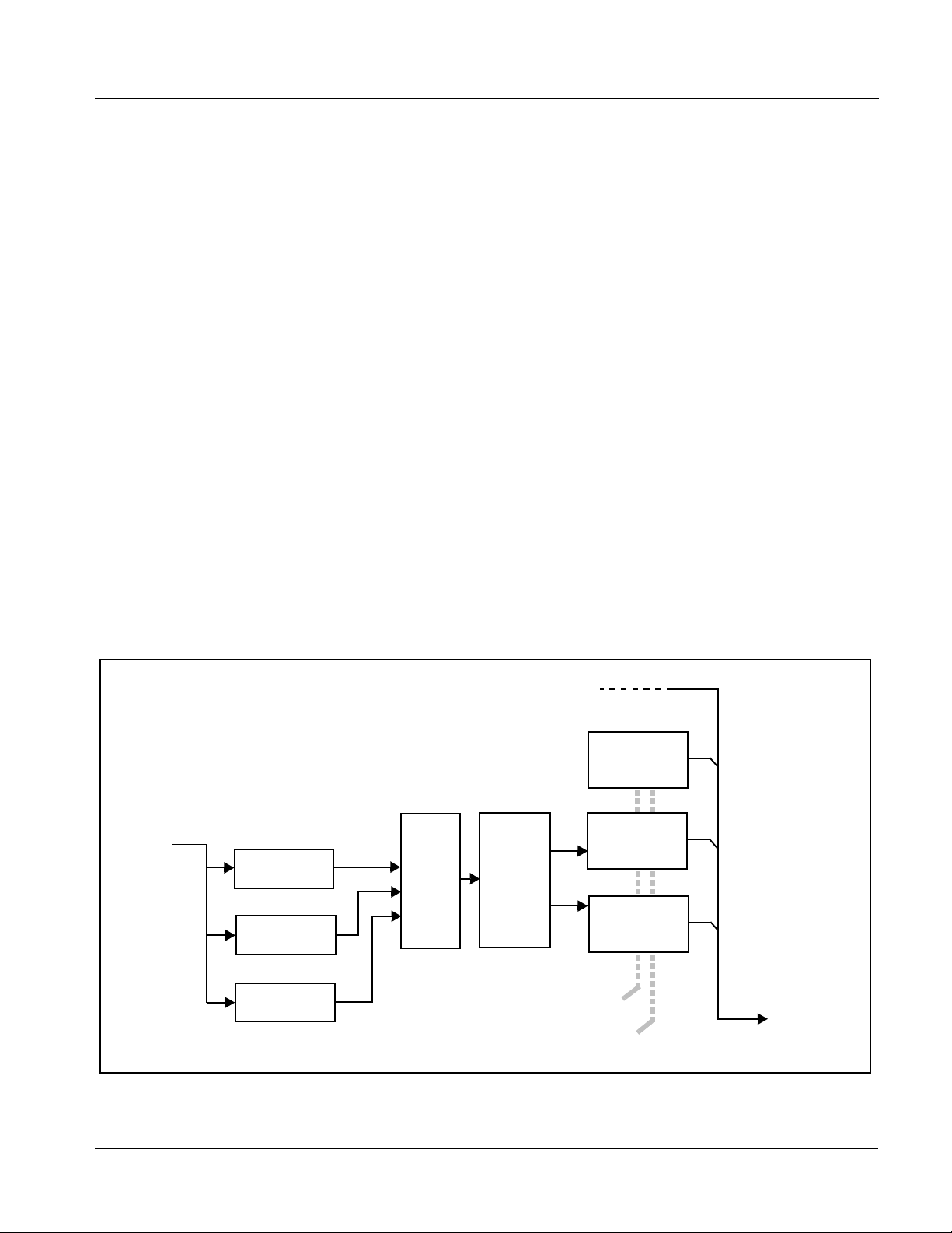
Figure 1-1 shows a functional block diagram of the 9064. The 9064 up/down/
cross-format converter also includes an RGB color corrector and a full video
frame synchronizer. The 9064 also handles AFD code dete ction/ i nsertio n and
processing, timecode support, a nd closed captioni ng support . Aspect r atio can
be corrected to provide proper output aspect.
Note: Some of the functions described below are available only when using the
9064 Input/Output Formats
Video Processor Description
DashBoard™, or Cobalt
user interfaces. Refer to User Control Interface (p. 1-12) for user interface
descriptions.
®
OGCP-9000 or OGCP-9000/CC Control Panels
The 9064 provides the following inputs and outputs:
• Inputs:
• HD/SD SDI IN – dual-rate HD/SD-SDI input
• Outputs:
• SDI OUT – four SD-SDI buffered video outputs
• RCK OUT– four SD-SDI reclocked buffered video outputs
The 9064 features a scaler that provide s up, down, and cross- conversion usi ng
de-interlacing and motion adaptation for high quality up-conversions. The
scaler also provides user-adjustable aspect ratio control and zoom control.
Separate controls are provided for SD and HD inputs that allow the card to
flexibly and independently handle mixed input formats.
The 9064 video subsystem also provides the functions described below.
Video Processor
The 9064 provides full color processing control (luma gain and lift, chroma
saturation, and color phase) of the output video. The 9064 video processor
also provides white, black, and chroma clip control. Clipping can be applied
with either a hard or soft white clip and also a chroma saturation clip. Luma
and chroma gain controls can be ganged to provide adjustment for both gain
controls.
9064-OM (V4.1) 9064 PRODUCT MANUAL 1-5
Page 10

1 9064 Functional Description
Color Corrector
The 9064 color corrector converts the YCbCr SDI input video to the 4:4:4
RGB color space (where the color correction is applied), and then back to
YCbCr SDI on the output. Controls are available to adjust each RGB level
independently for both white levels (gain) and black levels (offset). Gamma
can also be independently adjusted for each RGB channels. Various controls
can be ganged to provide adjustment for all three color channels
simultaneously.
Frame Sync Function
This function provides for frame sync control using either one of two external
EXT REF IN (1,2) reference signa ls dis trib uted wit h th e card f rame, or the i nput
video as a frame sync reference.
This function allows horizo nta l and/or vertical of fs et to be add ed between the
output video and the frame sync reference.
A Reset Framesync function re sets the frame sync following any hor izontal or
vertical offset changes, clearing any buffered video and re-establishing the
frame sync.
In the event of input video loss of signal, this function provides for disabling
the video, going to a desired color raster, or freezing to the last intact frame
(frame having valid SAV and EAV codes).
1-6 9064 PRODUCT MANUAL 9064-OM (V4.1)
Page 11
Introduction 9064 Functional Description
RCK
OUT
AFD
Processing
YCbCr
Sync
Frame
Limiting
SDI
OUT
Serializer/
Cable Drivers
Video
Processing
Up/Down/
Reclock
Conversion
Cross-Format
Video Processor
YCbCr
RGB
Correction
Proc
TC/CC
Processing
Color Corrector
Deserialize
EQ
SDI IN
IN (1,2)
EXT REF
HD/SD
9064BD
Figure 1-1 9064 Functional Block Diagram
9064-OM (V4.1) 9064 PRODUCT MANUAL 1-7
Page 12
1 9064 Functional Description
Scaler Function
The scaler function provides up, down, and cross-conversions between
multiple standard SD and HD video formats, multiple frame rates, film frame
rates, and cross-c onversion bet ween interla ced and progre ssive formats . T a ble
1-1 lists the 9064 conversion choices available for various input formats and
frame rates.
Table 1-1 Scaler Function Conversions
Input
Format
525i 59.94 525i 59.94 720p 59.94 720p 29.97 720p 23.98
SD
(NTSC/
PAL)
720p
720p
half-rate
720p
(film rates)
(4)
1080i 1080p
1080p
(film rates)
1080i 59.94 1080p 29.97 1080p 23.98
1080PsF 23.98
(4)
1080PsF
(film rates)
625i 50 625i 50 720p 50 720p 25 X 1080i 50 1080p 25 X X
720p 60 X 720p 60 720p 30 720p 24
(4)
720p 59.94 525i 59.94 720p 59.94 720p 29.97 720p 23.98
1080i 60 1080p 30 1080p 24
1080i 59.94 1080p 29.97 1080p 23.98
(4)
(4)
(4)
1080PsF 24
(4)
1080PsF 23.98
720p 50 625i 50 720p 50 720p 25 X 1080i 50 1080p 25 X X
720p 30 X 720p 60 720p 30 720p 24
(5)
720p 29.97 525i 59.94 720p 59.94 720p 29.97 720p 23.98
1080i 60 1080p 30 1080p 24
1080i 59.94 1080p 29.97 1080p 23.98
(5)
(5)
(5)
1080PsF 24
(5)
1080PsF 23.98
720p 25 625i 50 720p 50 720p 25 X 1080i 50 1080p 25 X X
720p 24 X 720p 60 720p 30 720p 24 1080i 60 1080p 30 1080p 24 1080PsF 24
720p 23.98 525i 59.94 720p 59.94 720p 29.97 720p 23.98 1080i 59.94 1080p 29.97 1080p 23.98 1080PsF 23.98
1080i 60 X 720p 60 720p 30 720p 24
(4)
1080i 59.94 525i 59.94 720p 59.94 720p 29.97 720p 23.98
1080i 60 1080p 30 1080p 24
1080i 59.94 1080p 29.97 1080p 23.98
(4)
(4)
(4)
1080PsF 24
(4)
1080PsF 23.98
1080i 50 625i 50 720p 50 720p 25 X 1080i 50 1080p 25 X X
1080p 30 X 720p 60 720p 30 720p 24
(5)
1080p 29.97 525i 59.94 720p 59.94 720p 29.97 720p 23.98
1080i 60 1080p 30 1080p 24
1080i 59.94 1080p 29.97 1080p 23.98
(5)
(5)
(5)
1080PsF 24
(5)
1080PsF 23.98
1080p 25 625i 50 720p 50 720p 25 X 1080i 50 1080p 25 X X
1080p 24 X 720p 60 720p 30 720p 24 1080i 60 1080p 30 1080p 24 1080PsF 24
1080p 23.98 525i 59.94 720p 59.94 720p 29.97 720p 23.98 1080i 59.94 1080p 29.97 1080p 23.98 1080PsF 23.98
1080PsF 24 X 720p 60 720p 30 720p 24 1080i 60 1080p 30 1080p 24 1080PsF 24
1080PsF 23.98 525i 59.94 720p 59.94 720p 29.97 720p 23.98 1080i 59.94 1080p 29.97 1080p 23.98 1080PsF 23.98
Notes: 1. The drop-down list choice of “Same as Input” is used when no conversion is desired. For clarity, it is not redundantly listed here.
2. “X” denotes conversions not available or invalid conversions.
3. Interlaced formats rates listed are field rates. Progressive format rates listed are frame rates.
4. If the original material does not have a proper 3-2 cadence suitable for conversion to film rates, the conversion reverts to standard
de-interlacing. While this video can be converted to film rates, the resulting image motion will lack smoothness. Therefore, make
certain interlaced video is appropriately constructed for 3-2 reverse pulldown when converting video to film rates. See 3-2
Pulldown Conversion and Considerations (p. 1-11).
5. Formats using a 30/29.97 Hz progressive frame rate can be converted to a 24/23.98 Hz progressive frame rate, however some
image motion irregularity will appear in the converted output.
6. “NTSC” and “PAL” in this manual informally denote 486i5994 and 575i50 SD-SDI video formats.
(4)
(4)
(5)
(4)
(5)
1-8 9064 PRODUCT MANUAL 9064-OM (V4.1)
Page 13
Introduction 9064 Functional Description
When output video is set to 720p for either SD or HD video, the 720p output
can be converted to 7 20p half-r ate for mats as lis ted in Table 1-1. When output
video is set to 1080 film (1080p23.98) for either SD or HD inputs, the 9064
can convert the output to 1080P sF23. 98 (seg mente d frame progre ssive) . Both
of these functions c an be i ndepend ently appli ed to e ither SD and/o r HD vide o
inputs.
The scaler function also provides aspect ratio conversion that provides a
choice from several standard aspect ratios. Additionally, user defined and
“Follow AFD Settings” conversion can be applied. User defined settings
allow custom user-defined H and V aspect ratio control. “Follow AFD
Settings” sets the output aspect ratio to track with AFD (Active Format
Description) settings embedded in the video signal.
Timecode Processor
(See Figure 1-2.) This fun ct ion provi de s for ext rac ti on of time code data fro m
the input video, and in turn re-insertion of timecode data into the output SDI.
In this manner, timecode data can be preserved, even aft er fo rmat conv ersi on.
The function can monitor the SDI video input of the card for supported
timecode formats, and then select and prioritize among SDI VITC, SDI
ATC_VITC, and SDI ATC_LTC timecode sources. If the preferred format is
detected, the preferred format is used by the ca rd; if the pre ferred format is
not detected, the card uses other formats (where available) as desired.
SDI
Video
Input
SDI VITC
Detect/Extract
SDI ATC_VITC
Detect/Extract
SDI ATC_LTC
Detect/Extract
The function also provides conversion between various received timecode
formats and provides insertion, line number control, and re-formatting to
SDI VITC, ATC_VITC, and/or ATC_LTC timecode output formats.
HD/SD–SDI
(From Video Proc/
Format Converter)
VITC Waveform
Timecode
Proc/Embed
ATC_VITC
Timecode
Priority/
Select
Buffer/
Re-format
Proc/Embed
SDI VITC
Timecode
Proc/Embed
Insert
Control
Line
Number
Control
HD/SD–SDI
Video Output
Figure 1-2 Timecode Processor
9064-OM (V4.1) 9064 PRODUCT MANUAL 1-9
Page 14

1 9064 Functional Description
Closed Captioning Processor
This function provides support for closed captioning setup. The function
receives closed captioning data from the incoming SDI stream and outputs
closed captioning on a selectable VANC line number when the output is HD
(for an SD output, the line number is fixed at line 21).
AFD Processor
This function provides aspect ratio controls and assignment of AFD codes to
the SDI output video.
Using this function, aspect ratios in accordanc e with the standard 4-bit AFD
codes can be applied to the output video. Additionally, custom aspect ratios
can be independently defined for any of the AFD codes.
Separate, independent AFD controls a re provided for both 16:9 coded and 4:3
coded frames.
This function also provides AFD-controlled ARC by checking for any
existing AFD code within the received video input. If a code is present, the
code is displayed. With the Scaler function
Follow AFD Settings, the H and V settings corr esponding to the received code
are applied to the video by the 9064. The default, standard aspect ratio
described by the AFD code can be applied, or custom horizontal/vertical
scaling can be applied for a given code.
Aspect Ratio Conversion set to
The function also allows the selection/changing of the AFD code ancillary
data line number for the outputted AFD code.
1-10 9064 PRODUCT MANUAL 9064-OM (V4.1)
Page 15
Introduction 9064 Functional Description
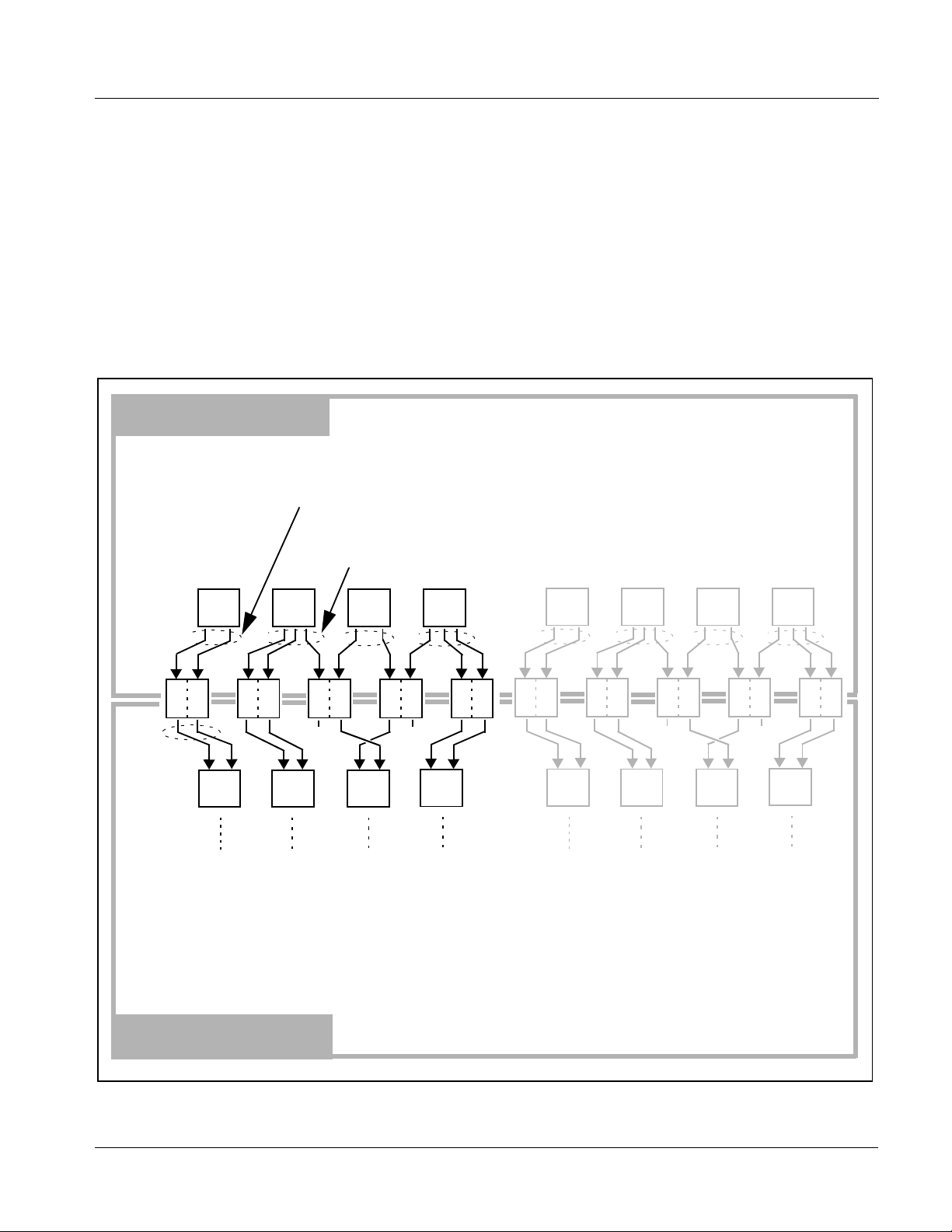
3-2 Pulldown Conversion and Considerations
Figure 1-3 depicts the 3-2 pulldown process used for conversions between
progressive film video formats and interlaced video formats. (Although the
term “3-2” is used here per convention, it is more accurately described as 2-3
per the diagram here and SMPTE definitions which stipulate that first film
frame
A be represented exclusively by 2 fields from the same frame). As
shown in Figure 1-3, the term 2-3 is derived from the pattern, or cadence, in
which four consecut iv e f il m vid eo f ra me s a re conv erted into five conse cut ive
interlaced video frames (i.e., 10 interlaced video fields). Odd and even interlaced fields are denoted in Figure 1-3 by “
“
A
”). Note the considerations described in Figure 1-3 for converting to film
E
rates.
3-2 Pulldown
(From 1080p 24 To 1080i 60)
“
2” portions consist of two consecutive interlaced fields sourced from the same film
frame. The first film frame and first video frame are unique as a set in that their
contents are mutually and exclusively related to each other.
” and “E” (for exampl e, “AO” and
O
1080p 24
1080i 60
1080i 60
1080p 24
“3” portions consist of three consecutive interlaced fields sourced from the
same film frame distributed across three consecutive interlaced fields.
A B C D
1
AOA
3
2
BOB
E
E
3
BOC
X
2
E
A B C
AOA
[1O1E]
Using reverse pulldown, each film video frame is constructed from 2 interlaced fields with odd and even fields selected
as shown. The conversion pattern shown reverses the pulldown, thereby restoring the original signal.
Note:If the original interlaced material does not have the cadence described here, the conversion reverts to standard
de-interlacing. While this video can be converted to film rates, the resulting image motion will lack smoothness.
Therefore, make certain interlaced video is appropriately constructed for reverse pulldown when converting video to film
rates. Similarly, formats using a 30/29.97 Hz progressive frame rate can be converted to a 24/23.98 Hz progressive
frame rate, however some image motion irregularity will appear in the converted output.
BOB
[2O2E]
E
E
COC
[4O3E]
32
45
COD
X
DOD
E
E
D
DOD
E
E
[5O5E]
A B C D
2
1
AOA
2
BOB
E
E
3
BOC
X
E
A B C
AOA
[1O1E]
BOB
E
E
[2O2E]
COC
[4O3E]
32 3
45
COD
E
X
E
DOD
[5O5E]
DOD
E
D
E
3-2 Reverse Pulldown
From 1080i 60 To 1080p 24
Figure 1-3 3-2 Pulldown and Reverse Pulldown
9064-OM (V4.1) 9064 PRODUCT MANUAL 1-11
Page 16
1 9064 Functional Description
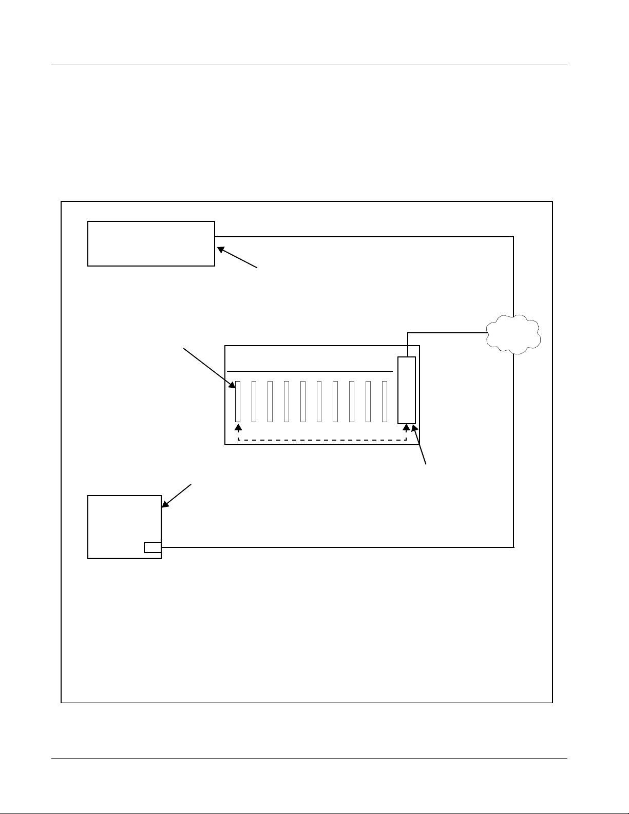
User Control Interface
Figure 1-4 shows the user control interface options for the 9064. These
options are individually described below.
Note: All user control interfaces described here are cross-compatible and can oper-
ate together as desired. Where applicable, any control setting change made
using a particular user interface is reflected on any other connected interface.
OGCP-9000 Control Panel
OGCP-9000/CC Control Panel
Card Edge Controls
9064 card can be
controlled using built-in
card edge controls
Computer
with NIC
or
DashBoard™ Remote Control
Using a computer with
DashBoard™ installed, 9064
card can be remotely controlled
over a LAN
Remote Control Panel
Using the Control Panel,
9064 card can be remotely
controlled over a LAN
LAN
20-Slot Frame with MFC-8320-N network
controller card
In conjunction with a frame equipped
with an MFC-8320-N network
controller card, 9064 card can be
remotely controlled over a LAN
Note: • To communicate with DashBoard™ or a Remote Control Panel, the frame must have the optional
MFC-8320-N network controller card installed.
• DashBoard™ and the Remote Control Panels provide network control of the 9064 as shown. The
value displayed at any time on the card, or via DashBoard™ or a Control Panel is the actual value
as set on the card, with the current value displayed being the actual value as effected by the card.
Parameter changes made by any of these means are universally accepted by the card (for
example, a change made using the card edge controls will change the setting displayed on
DashBoard™ and a Control Panel; a change made using DashBoard™ will similarly change the
setting displayed on a Control Panel and the card itself).
Figure 1-4 9064 User Control Interface
1-12 9064 PRODUCT MANUAL 9064-OM (V4.1)
Page 17

Introduction 9064 Functional Description
• Built-in Card Edge User Interface – Using the built-in card edge
controls and display, card control settings can be set using a front
panel menu which is described in Chapter 3,“Operat ing Inst ruction s”.
Note: Some of the 9064 functions described in this manual are available only when
using the DashBoard™, or Cobalt
Control Panel user interfaces.
• DashBoard™ User Interface – Using DashBoard™, the 9064 and
other cards installed in openGear®
®
OGCP-9000 or OGCP-9000/CC Remote
1
frames such as the Cobalt®
HPF-9000 or 8321 Frame can be controlled from a computer and
monitor.
DashBoard™ allows users to view all frames on a network with
control and monitoring for all populated slots inside a frame. This
simplifies the setup and use of numerous modules in a large
installation and offers the ability to centralize monitoring. Cards
define thei r controllable parameters to DashBoard™, so the control
interface is always up to date.
The DashBoard™ software can be downloaded from the Cobalt
Digital Inc. website: www.cobaltdigital.com
(enter “DashBoard” in
the search window). The DashBoard™ user interface is describe d in
Chapter 3,“Operating Instructions”.
Note: If network remote control is to be used for the frame and the frame has not yet
been set up for remote control, Cobalt
Control User Guide” (PN 9000RCS-RM) provides thorough information and
step-by-step instructions for setting up network remote control of
COMPASS
Download a copy of this guide by clicking on the Support>Downloads link at
www.cobaltdigital.com and then select DashBoard Remote Control Setup
Guide as a download, or contact Cobalt
Inc. (p. 1-19).
®
cards using DashB oard™.
®
reference guide COMPASS® Remote
®
as listed in Contact Cobalt Digital
• Cobalt
®
OGCP-9000 and OGCP-9000/CC Remote Control
Panels – The OGCP-9000 and OGCP-9000/CC Remote Control
Panels conveniently and intuitively provide parameter monitor and
control of the 9064 and other video and audio processing terminal
equipment meeting the open-architecture Cobalt COMPASS
®
cards
for openGear™ standard.
In addition to circumventing the need for a computer to monitor and
control signal processing cards, the Control Panels allow quick and
intuitive acces s to hundre ds of car ds in a fac ility, and can monitor and
allow adjustment of multiple parameters at one time.
The Remote Control Panels are totally compatible with the
openGear™ control software DashBoard™; any changes made with
either system are reflected on the other. The Remote Control Panel
user interface is described in Chapter 3,“Operating Instructions”.
1. openGear® is a registered trademark of Ross Video Limited. DashBoard™ is a trademark of Ross
Video Limit e d .
9064-OM (V4.1) 9064 PRODUCT MANUAL 1-13
Page 18
1 9064 Functional Description
9064 Rear I/O Modules
The 9064 physically interfaces to system video connections at the rear of its
frame using a Rear I/O Module.
All inputs and outputs shown in the 9064 Functional Block Diagram (Figure
1-1) enter and exit the card via the card edge backplane connector. The
Rear I/O Module breaks out the 9064 card edge connections to BNC
connectors that interface with other components and systems in the signal
chain.
These required BNC connections are provided by either an 8310-BNC or
8310-C-BNC frame (which both have a built-in BNC connector backplane
module), or by using an optional RM20-9064-A Rear I/O Module.
Video Formats Supported by the 9064
The 9064 supports all current SMPTE standard SD and HD video formats.
Table 1-2 lists and provides details regarding the video formats supported by
the 9064.
Table 1-2 Supported Video Formats
Item Description/Specification
Input / Output Video Raster Structure: Frame Rate:
1080PsF 23.98; 24
1080p 23.98; 24
(1)
1080i
720p 23.98; 24; 25; 29.97; 30; 50; 59.94;
(1)
486i
(1)
575i
(1) All rates displayed as frame rates; interlaced (“i”) field rates are two times the rate value shown.
25; 29.97; 30
60
29.97
25
1-14 9064 PRODUCT MANUAL 9064-OM (V4.1)
Page 19

Introduction Technical Specifications
Technical Specifications
Table 1-3 lists the technical specifications for the 9064 Up/Down/Cross
Converter with HD/SD-SDI Input, RGB Color Corrector, and Frame Sync
card.
Table 1-3 Technical Specifica tions
Item Characteristic
Part number, nomenclature 9064 Up/Down/Cross Converter with HD/SD-SDI Input, RGB
Color Corrector, and Frame Sync
Installation/usage environment Intended for installation and usage in frame meeting openGear®
modular system definition.
Power consumptio n < 17 Watts maximum
Environmental:
Operating temperature:
Relative humidity (operating or storage):
32° – 104° F (0° – 40° C)
< 95%, non-condensing
Frame communication 10/100 Mbps Ethernet with Auto-MDIX.
Indicators Card edge display and indicators as follows:
• 4-character alphanumeric display
• Status/Error LED indicator
• Input For mat LED indic ato r
Controls Card edge switches as follows:
• Menu Enter pushbutton switch
• Menu Exit pushbutton switch
• Up/down selection toggle switch
Resolution: 10-bit video data path
Serial Digital Video Input Data Rates Supported:
SMPTE 292 HD-SDI: 1.485 Gbps or 1.485/1.001 Gbps
SMPTE 259M-C SD-SDI: 270 Mbps
Impedance:
75 Ω terminating
Equalization (HD):
260 ft (79 m) Belden 1694A
Equalization (SD):
1000 ft (305 m) Belden 1694A
Return Loss:
> 15 dB at 5 MHz – 1.485 GHz
9064-OM (V4.1) 9064 PRODUCT MANUAL 1-15
Page 20

1 Technical Specifications
Table 1-3 Technical Specifications — continued
Item Characteristic
Post-Processor Serial Digital Video
Outputs
Pre-Proces sor (Rec locked) Se rial Digi tal
Video Outputs
Number of Outputs:
Four SD-SDI BNC per IEC 60169-8 Amendment 2
Impedance:
75 Ω
Return Loss:
> 15 dB at 5 MHz – 270 MHz
Signal Level:
800 mV ± 10%
DC Offset:
0 V ± 50 mV
Jitter (HD):
< 0.15 UI (all outputs)
Jitter (SD):
< 0.10 UI (all outputs)
Overshoot:
< 0.2% of amplitude
Number of Outputs:
Four SD-SDI BNC per IEC 60169-8 Amendment 2
Impedance:
75 Ω
1-16 9064 PRODUCT MANUAL 9064-OM (V4.1)
Page 21

Introduction Technical Specifications
Table 1-3 Technical Specifica tions — continued
Item Characteristic
Reference Video Input Number of Inputs:
Two non-terminating (looping) Frame Reference inputs
Standards Supported (HD):
720p 25; 29.97; 50; 59.94
1080i 25; 29.97
1080p 23.98; 25; 29.97
1080p/sF 23.98
Standards Supported (SD):
486i 29.97 (NTSC)
575i 25 (PAL)
Signal Level:
1 Vp-p nominal
Signal Type:
Analog video sync (black burst or tri-level)
Impedance:
75 Ω
Return Loss:
> 30 dB to 30 MHz
Allowable Maximum DC on Ref Input:
±1.0 V
9064-OM (V4.1) 9064 PRODUCT MANUAL 1-17
Page 22

1 Warranty and Service Information
Warranty and Service Information
Cobalt Digital Inc. Limited Warranty
This product is warranted to be free from defects in material and workmanship for a period of five (5)
years from the date of shipment to the original purchaser, except that 4000, 5000, 6000, 8000 series
power supplies, and Dolby
material and workmanship for a period of one (1) year.
Cobalt Digital Inc. 's (“Cobalt”) sole obligation under this warranty shall be limited to, at its option, (i)
the repair or (ii) replacement of the product, and the determinati on of whether a defect is covered under
this limited warranty shall be made at the sole discretion of Cobalt.
This limited warranty applies onl y to the original end-purchaser of the pr oduct, and is not assigna ble or
transferrable therefrom. This warranty is limited to defects i n material a nd workman shi p, and shal l not
apply to acts of God, accidents, or negligence on behalf of the purchaser, and shall be voided upon the
misuse, abuse, alteration, or modification of the product. Only Cobalt authorized factory
representatives are authorized to make repairs to the product, and any unauthorized attempt to repair
this product shall immediately void the warranty. Please contact Cobalt Technical Support for more
information.
®
modules (where applicable) are warranted to be free from defects in
To facilitate the resolution of warranty related issues , Cobalt recommends registering the product by
completing and returning a product registration form. In the event of a warrantable defect, the
purchaser shall notify Cobalt with a description of the problem, and Cobalt shall provide the purchaser
with a Return Material Authorization (“RMA”). For return, defective product s should be double boxed,
and sufficiently protected, in the original packaging, or equivalent, and shipped to the Cobalt Factory
Service Center, postage prepaid and insured for the purchase price. The purchaser should include the
RMA number, description of the problem encountered, date purchased, name of dealer purchased
from, and serial number with the shipment.
Cobalt Digital Inc. Factory Service Center
2406 E. University Avenue Office: (217) 344-1243
Urbana, IL 61802 USA Fax: (217) 344-1245
www.cobaltdigital.com Ema il: info@cobaltdigital.com
THIS LIMITED WARRANTY IS EXPRESSLY IN LIEU OF ALL OTHER WARRANTIES
EXPRESSED OR IMPLIED, INCLUDING THE WARRANTIES OF MERCHANTABILITY AND
FITNESS FOR A PARTICULAR PURPOSE AND OF ALL OTHER OBLIGATIONS OR
LIABILITIES ON COBALT'S PART. ANY SOFTWARE PROVIDED WITH, OR FOR USE WITH,
THE PRODUCT IS PROVIDED “AS IS.” THE BUYER OF THE PRODUCT ACK NOWLEDGES
THAT N O OTHER REPRESENTATIONS WERE MADE OR RELIED UPON WITH RESPECT TO
THE QUALITY AND FUNCTION OF THE GOODS HEREIN SOLD. COBALT PRODUCTS ARE
NOT AUTHORIZED FOR USE IN LIFE SUP PORT APPLICATIONS.
COBALT'S LIABILITY, WHETHER IN CONTRACT, TORT, WARRANTY, OR OTHERWISE, IS
LIMITED TO THE REPAIR OR REPLACEMENT, AT ITS OPTION, OF ANY DEFECTIVE
PRODUCT, AND SHALL IN NO EVENT INCLUDE SPECIAL, INDIRECT, INCIDENTAL, OR
CONSEQUENTIAL DAMAGES (INCL UDING LOST PROFITS), EVEN IF IT HAS BEEN
ADVISED OF THE POSSIBILITY OF SUCH DAMAGES.
1-18 9064 PRODUCT MANUAL 9064-OM (V4.1)
Page 23
Introduction Contact Cobalt Digital Inc.
Contact Cobalt Digital Inc.
Feel free to contact ou r th oro ugh and professional support representatives for
any of the following:
• Name and address of your local dealer
• Product information and pricing
• Technical support
• Upcoming trade show i nformation
Phone: (217) 344-1243
Fax: (217) 344-1245
Web: www.cobaltdigital.com
General Information: info@cobaltdigital.com
Technical Support: support@cobaltdigital.com
9064-OM (V4.1) 9064 PRODUCT MANUAL 1-19
Page 24

This page intentionally blank
1-20 9064 PRODUCT MANUAL 9064-OM (V4.1)
Page 25
Chapter 2 Installation and Setup
Overview
This chapter contains the following information:
• Installing the 9064 Into a Frame Slot (p. 2-1)
• Installing a Rear I/O Module (p. 2-4)
• Setting Up 9064 Network Remote Control (p. 2-5)
Installing the 9064 Into a Frame Slot
Chapter 2
CAUTION
Heat and power distribution requirements within a frame may dictate specific
slot placement of cards. Cards with many heat-producing compon ents should
be arranged to avoid areas of excess heat build-up, particularly in frames
using only convection cooling. The 9064 has a moderate power dissipation
(17 W max.). As such, avoiding placing the card adjacent to other cards with
similar dissipation values if possible.
CAUTION
This device contains semiconductor devices which are
susceptible to serious damage from Electrostatic
Discharge (ESD). ESD damage may not be immediately
apparent and can affect the long-term reliability of the
device.
Avoid handling circuit boards in high static environments
such as carpeted areas, and when wearing synthetic fiber
clothing. Always use proper ESD handling precautions
and equipment when working on circuit boards and
related equipment.
9064-OM (V4.1) 9064 PRODUCT MANUAL 2-1
Page 26

2 Installing the 9064 Into a Frame Slot
Note: • If installing the 9064 in an 8310-C-BNC or 8310-BNC frame (which is
pre-equipped with a 100-BNC rear I/O module installed across the entire
backplane) or a slot already equipped with a suitable I/O module, proceed to
card installation steps below.
• If installing the 9064 in a slot with no rear I/O module, a Rear I/O
Module is required before cabling can be connected. Refer to Installing a
Rear I/O Module (p. 2-4) for rear I/O module installation procedure.
CAUTION
If required, make certain Rear I/O Module(s) is installed before installing the
9064 into the frame slot. Damage to card and/or Rear I/O Module can occur if
module installation is attempted with card already installed in slot.
Note: Check the packaging in which the 9064 was shipped for any extra items such
as a Rear I/O Module connection label. In some cases, this label is shipped
with the card and to be installed on the Rear I/O connector bank corresponding to the slot location of the card.
Install the 9064 into a frame slot as follows:
1. Determine the slot in which the 9064 is to be installed.
2. Open the frame front access panel.
3. While holding the card by the card edges, align the card such that the
plastic ejector tab is on the bottom.
4. Align the card with the top and bottom guides of the slot in which the
card is being installed.
5. Gradually slide the card into the slot. When re sistance is noticed, gently
continue pushing the card until its rear printed circuit edge terminals
engage fully into the rear I/O module mating connector.
CAUTION
If card resists fully engaging in rear I/O module mating connector, check for
alignment and proper insertion in slot tracks. Damage to card and/or rear I/O
module may occur if improper card insertion is attempted.
Verify that the card is fully engaged in rear I/O module mating connector.
6.
7. Close the frame front access panel.
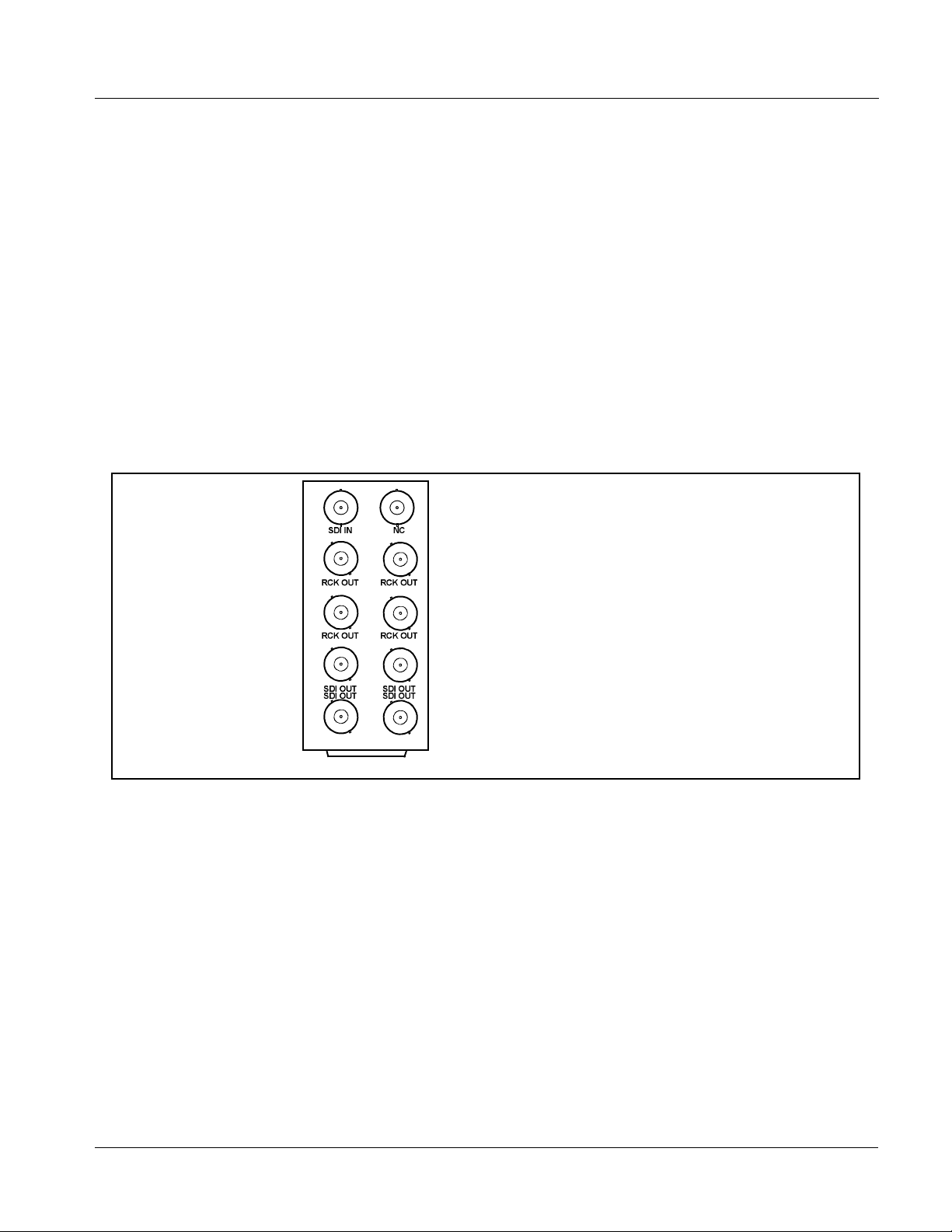
8. Connect the input and output cables as shown in Figure 2-1.
9. Repeat steps 1 through 8 for other 9064 cards.
2-2 9064 PRODUCT MANUAL 9064-OM (V4.1)
Page 27
Installation and Setup Installing the 9064 Into a Frame Slot
Note: The 9064 BNC inputs are internally 75-ohm terminated. It is not necessary to
terminate unused BNC inputs or outputs.
Note: External frame sync reference signals are received by the card over a refer-
ence bus on the card frame, and not on any card rear I/O module connectors.
The frame has BNC connectors labeled REF 1 and REF 2 which receive the
reference signal from an external source such as a house distribution.
Note: To remove a card, press down on the ejector tab to unseat the card from the
rear I/O module mating connector. Evenly draw the card from its slot.
10. If network remote control is to be used for the frame and the frame has
not yet been set up for remote control, perform setup in accordance with
Setting Up 9064 Network Remote Control (p. 2-5).
Note: If installing a card in a frame already equipped for, and connected to
DashBoard™, no network setup is required for the card. The card will be discovered by DashBoard™ and be ready for use.
Both the built-in Rear I/O Modules on the 8310-BNC/
8310-C-BNC frames and the optional RM20-9064-A Rear I/
O Module use the connector arrangements shown to the left.
Connect cabling as shown. Unused connectors do not
require external termination.
RM-9064-A.PNG
Figure 2-1 9064 Rear I/O Module Connections
9064-OM (V4.1) 9064 PRODUCT MANUAL 2-3
Page 28
2 Installing a Rear I/O Module
Installing a Rear I/O Module
Note: This procedure is applicable only if a Rear I/O Module is not currently
installed in the slot where the 9064 is to be installed.
If installing the 9064 in a 8310-C-BNC or 8310-BNC frame (which is
pre-equipped with a 100-BNC rear I/O module installed across the entire
backplane) or a slot already equipped with a suitable I/O module, omit this
procedure.
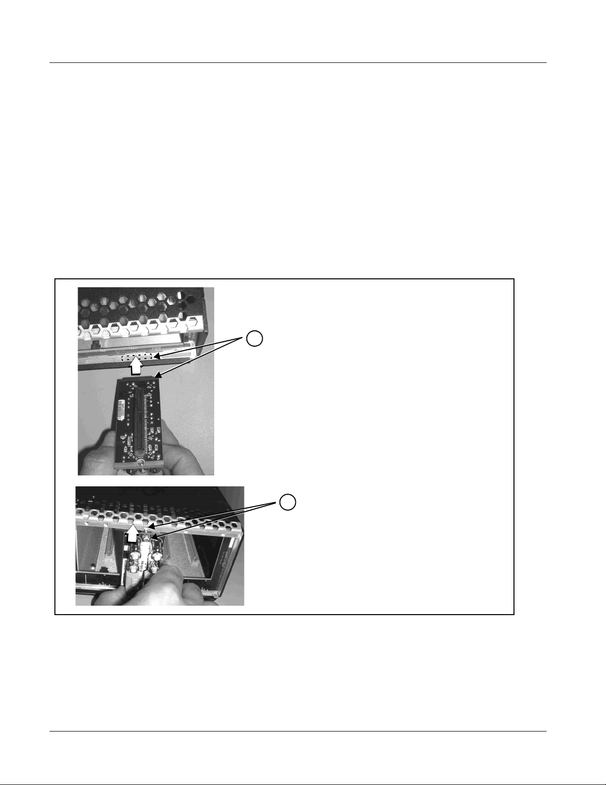
Install a Rear I/O Module as follows:
1. On the frame, determine the slot in which the 9064 is to be installed.
2. In the mounting area corresponding to the slot location, install
Rear I/O Module as shown in Figure 2-2.
DSCN3483A.JPG
DSCN3487A.JPG
Align and engage mounting tab on Rear
I/O Module with the module seating slot
1
on rear of frame chassis.
Hold top of Rear I/O Module flush against
frame chassis and start the captive screw.
2
Lightly tighten captive screw.
Figure 2-2 Rear I/O Module Installation
2-4 9064 PRODUCT MANUAL 9064-OM (V4.1)
Page 29

Installation and Setup Setting Up 9064 Network Remote Control
Setting Up 9064 Network Remote Control
Perform remote control setup in accordance with Cobalt® reference guide
“COMPASS
Note: • If network rem ote control is to be used for the frame and the frame has not
yet been set up for remote control, Cobalt
Remote Control User Guide (PN 9000RCS-RM) provides thorough information and step-by-step instructions for setting up network remote control of
COMPASS™ cards u sing Das hB oard ™. (Cobalt
OGCP-9000/CC Remote Control Panel product manuals have complete
instructions for setting up remote control using a Remote Control Panel.)
Download a copy of this guide by clicking on the Support>Downloads link
at www.cobaltdigital.com and then select DashBoard Remote Control Setup
Guide as a download, or contact Cobalt
Inc. (p. 1-19).
• If installing a card in a frame already equipped for, and connected to
DashBoard™, no network setup is required for the card. The card will be discovered by DashBoard™ and be ready for use.
®
Remote Control User Guide” (PN 9000RCS-RM).
®
reference guide COMPASS™
®
OGCP-9000 and
®
as listed in Contact Cobalt Digital
9064-OM (V4.1) 9064 PRODUCT MANUAL 2-5
Page 30

This page intentionally blank
2-6 9064 PRODUCT MANUAL 9064-OM (V4.1)
Page 31

Overview
Chapter 3
Chapter 3 Operating Instructions
This chapter contains the following information:
If you are already familiar
with using DashBoard or a
Cobalt Remote Control
Panel to control Cobalt
cards, please skip to 9064
Function Submenu Li st and
Descriptions (p. 3-9).
• Control and Display Descriptions (p. 3-1)
• Accessing the 9064 Card via Remote Control (p. 3-5)
• Checking 9064 Card Information (p. 3-7)
• Ancillary Data Line Number Locations and Ranges (p. 3-8)
• 9064 Function Submenu List and Descriptions (p. 3-9)
• Color and Video Correction Examples Using the 9064 (p. 3-37)
• Troubleshooting (p. 3-44)
Control and Display Descriptions
This secti on describes the user interface controls, indicators, and displays for
using the 9064 card. The 9064 function s can be acces sed and contr olle d using
any of the user interfaces described here.
The format in which the 9064 functional controls, indicators, and displays
appear and are used varies depending on the user interface being used.
Regardless of the user interface being used, access to the 9064 functions (and
the controls, ind icato rs, an d disp lays r elat ed to a particul ar f uncti on) fo llows a
general arrangement of Function Submenus under which related controls can
be accessed (as described in Function Submenu/Parameter Submenu
Overview below).
Note: DashBoard™ and the Remote Control Panel provide greatly simplified user
interfaces as compared to using the card edge controls. For this reason, it is
strongly recommended that DashBoard™ or a Remote Control Panel be
used for all card applications other than the most basic cases. Card edge
control codes are not included in this manual. If card-edge control is to be
used, obtain a copy of “Manual Supplement – Card-Edge Control Reference
Master List and Instructions for Using Compass
Codes” (989CEC-MS.pdf) at
www.cobaltdigital.com>Support>Documents>Reference Guides.
9064-OM (V4.1) 9064 PRODUCT MANUAL 3-1
®
Card-edge (Local) Control
Page 32

3 Control and Display Descriptions
Note: When a setting is changed, settings displayed on DashBoard™ (or a Remote
Control Panel) are the settings as effected by the 9064 card itself and
reported back to the remote control; the value displayed at any time is the
actual value as set on the card.
Function Submenu/Parameter Submenu Overview
The functions and related pa rameters avai lable on the 9064 car d are organ ized
into function submenus, which consist of parameter groups as shown below.
Figure 3-1 shows how the 9064 card an d its submenus ar e orga nized, and also
provides an overview of how navig ation is performed be tween cards, func tion
submenus, and parameters.
If using DashBoard™ or a Remote Control Panel, the
desired 9064 card is first selected.
9064
Submenu a Submenu b
Individual Parameters
Each submenu consists of groups of parameters
related to the function submenu. Using the “Video
Proc” function submenu example, the individual
parameters for this function consist of various v ideo
processor parameters such as Luma Gain, Saturation,
and so on.
Figure 3-1 Function Submenu/Parameter Submenu Overvie w
• • •
The desired function submenu is next
selected.
Function Submenus consist of parameter
groups related to a particular 9064 card
function (for example, “Video Proc”).
Submenu z
3-2 9064 PRODUCT MANUAL 9064-OM (V4.1)
Page 33
Operating Instructions Control and Display Descriptions
DashBoard™ User Interface
(See Figure 3-2.) Th e 9064 fu nction submenus are or gani zed i n DashBoa rd™
using tabs. When a tab is selected, each parametric control or selection list
item associated with the function is displayed. Scalar (numeric) parametric
values can then be adjusted as desired using the GUI slider controls. Items in
a list can then be selected using GUI drop-down lists. (In this manner, the
setting effected using controls and selection lists displayed in DashBoard™
are comparable to the su bmenu ite ms access ed and commi tted using the 9064
card edge c ontrols.)
Typical On/Off
Control
Typical Parametric
Control
Typical Selection
List
DashBoard Tabs
Figure 3-2 Typical DashBoard Tabs and Controls
9064-OM (V4.1) 9064 PRODUCT MANUAL 3-3
Page 34
3 Control and Display Descriptions
Cobalt® Remote Control Panel User Interfaces
(See Figure 3-3.) Similar to the function submenu tabs using DashBoard™,
the Remote Control Panels have a Select Submenu key that is used t o dis pla y
a list of function submenus. From this list, a control knob on the Control
Panel is used to select a function from the list of displayed function submenu
items.
When the desired function submenu is selected, each parametric control or
selection list item associated with the function is displayed. Scalar (numeric)
parametric values can then be adjusted as desired using the control knobs,
which act like potentiometers. It ems in a list can then be selected using the
control knobs which correspo ndingly act like rotar y switches. (In thi s manner ,
the setting effected using co ntr ols and selection lists displayed on t h e Co ntr ol
Panel are comparable to t he submenu i tems acce ssed and committed u sing the
9064 card edge controls.)
Figure 3-3 shows accessing a function submenu and its parameters (in this
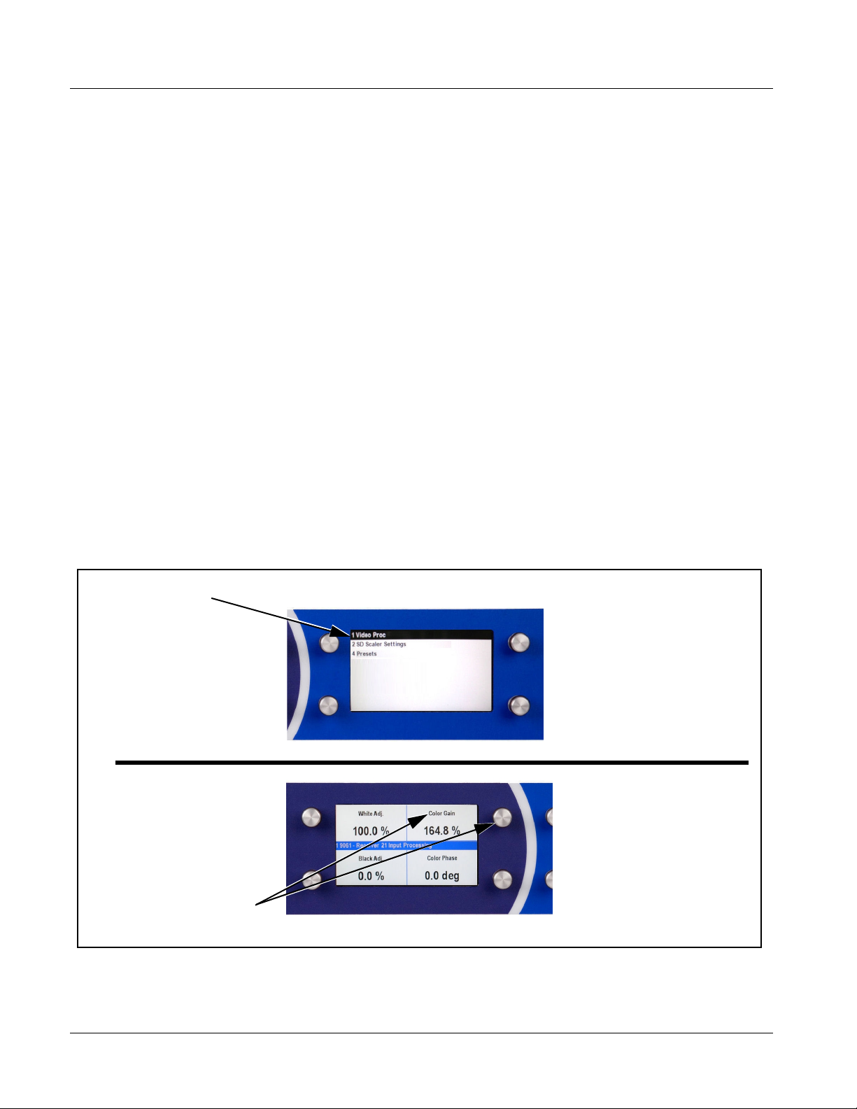
example, “Video Proc”) using the Control Panel.
Video Proc function
(among others) is
accessed using the Control
Panel Select Submenu
key. Video Proc function is
selected from the list of
functions (submenu items)
When the Video Proc
function submenu is
selected, its related
parameters are now
displayed.
Note: Refer to “OGCP-9000 Remote Control Panel User Manual” (PN
OGCP-9000-OM) or “OGCP-9000/CC Remote Control Panel Product
Manual” (PN OGCP-9000/CC-OM) for complete instructions on using the
Control Panels.
9064_3396B_3346B.JPG
In this example, Color Gain
(saturation) is adjusted using
the control knob adjacent to
Color Gain
Figure 3-3 Remote Control Panel Setup of Example Video Proc Function Setup
3370_3372B.JPG
3-4 9064 PRODUCT MANUAL 9064-OM (V4.1)
Page 35

Operating Instructions Accessing the 9064 Card via Remote Control
Accessing the 9064 Card via Remote Control
Access the 9064 card using DashBoard™ or Cobalt® Remote Control Panel
as described below.
Accessing the 9064 Card Using DashBoard™
1. On the computer connected to the frame LAN, open DashBoard™.
2. As shown be low, in the left side Basic View Tree locate the Network
Controller Card asso ci ated wi th th e fra me co ntain ing th e 9064 c ard t o be
accessed (in this example, “MFC-8320-N SN: 00108053”).
DB_ACCESS1.PNG
3. As shown below, expand the tree to access the cards within the frame.
Click on the card to be accessed (in this example,
“Slot 7: CDI-9064 RCVR21”).
.
9064_DB_ACCESS2A.PNG
As shown on the next page, when th e car d is access ed a DashBoa rd™ its
function submenu screen showing tabs for each function is displayed.
(The particular submenu screen displayed is the previously displayed
screen from the last time the card was accessed by DashBoard™).
9064-OM (V4.1) 9064 PRODUCT MANUAL 3-5
Page 36

3 Accessing the 9064 Card via Remote Control
Card Access/Navigation
Tree Pane
Card Info
Pane
Card Function Submenu
and Controls Pane
Accessing the 9064 Card Using a Cobalt® Remote Control Panel
Press the Select Device key and select a c ard as shown in the example below.
9064_3366_3392.JPG
This display shows the list
order number of the device that
is ready for selection
This display shows the devices assigned to the Control Panel.
• Rotate any knob to select from the list of devices. The device selected using a knob
is displayed with a reversed background (in this example,
“1 9064 - Receiver 21 Input Processing”).
• Directly enter a device by entering its list number using the numeric keypad, and
then pressing Enter or pressing in any knob).
9064_DB_ACCESS3A3.PNG
3-6 9064 PRODUCT MANUAL 9064-OM (V4.1)
Page 37
Operating Instructions Checking 9064 Card Information
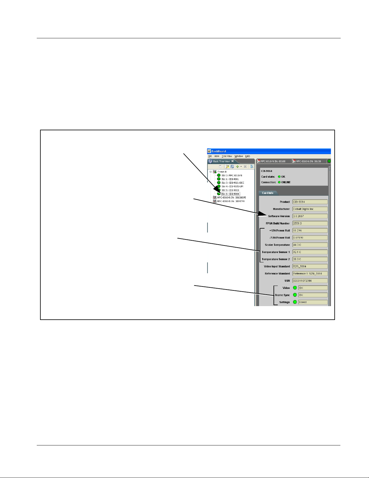
Checking 9064 Card Information
The operating st atus and s oftwar e ver sion the 9 064 car d can be chec ked us ing
DashBoard™ or the card edge control user interface. Figure 3-4 shows and
describes the 9064 card i nformati on screen usi ng DashBoard™ a nd acces sing
card information using the card edg e control user interfac e.
Note: Proper operating status in DashBoard™ is denoted by green icons for the sta-
tus indicators shown in Figure 3-4. Yellow or red icons respectively indicate
an alert or failure condition. Refer to Troubleshooting (p. 3-44) for corrective
action.
The Tree View shows the cards seen by DashBoard™.
In this example, Frame A is hosting a 9064 card in slot 6.
Software Version Number
Refer to these numbers to check that documentation (such as this
manual) matches the card’s Software Release Number and
Software Build Number. Use these numbers also when
communicating to Cobalt
®
regarding this card.
Power Consumption and Temperature Displays
This display shows the power consumed by the 9064
for both the +12V and -7.5V rails, as well as key device
temperatures.
Status Displays
These displays show the status the signal being received by
the 9064. Green Settings icon shows that any changes made
on DashBoard™ are sucessfully saved on the card’s memory.
Figure 3-4 9064 Card Info Utility
9064_CARD_INFO.PNG
9064-OM (V4.1) 9064 PRODUCT MANUAL 3-7
Page 38

3 Ancillary Data Line Number Locations and Ranges
Ancillary Data Line Number Locations and Ranges
Table 3-1 lists typical default output video VANC line number locations for
various ancillary data items that may be passed or handled by the card.
Table 3-1 Typical Ancillary Data Line Number Locations/Ranges
Default Line No. / Range
Item
SD HD
AFD 12 (Note 2) 9 (Note 2)
ATC_VITC 13 (Note 2) 9/8 (Note 2)
ATC_LTC — 10 (Note 2)
®
Dolby
Metadata 13 (Note 2) 13 (Note 2)
SDI VITC Waveform 14/16 (Note 2) —
Closed Captioning 21 (locked) 10 (Note 2)
Notes:
1. The card does not check for conflicts on a given line number. Make certain the selected line is available
and carrying no other data.
2. While range indicated b y d rop -dow n li st o n G UI m ay al lo w a particular range o f ch oi ces , the actual range
is automatically cl amped (limi ted) to c ert ain rang es to preven t inadv ertent con fli ct with a ctive pictu re ar ea
depending on video format. Limiting ranges for various output formats are as follows:
Format Line No. Limiting Format Line No. Limiting Format Line No. Limiting
525i 12-19 720p 9-25 1080p 9-41
625i 9-22 1080i 9-20
Because line number allocation is not standardized for all ancillary items,
consideration should be given to all items when performing set-ups. Figure
3-5 shows an example of improper and corrected VANC allocation within an
HD-SDI stream.
ATC_VITC = 9/8
CC = 10
Dolby Meta data = 13
Card 1
ATC_VITC = 9/ 8
CC = 10
Dolby Metadata = 13
Card 1
AFD Insertion
attempted usin g
VANC line 9
(default)
AFD Insertion
corrected to us e
VANC line 18
ATC_VITC = 9/8
AFD = 9
CC = 10
Dolby Meta data = 13
Card n
ATC_VITC = 9/8
CC = 10
Dolby Metadata = 13
AFD = 18
Card n
Conflict between
ATC_VITC and AFD both
on VANC line 9
Conflict between
ATC_VITC on line 9/8 and
AFD (now on line 18)
resolved
Figure 3-5 Example VANC Line Number Allocation Conflict and Resolution
3-8 9064 PRODUCT MANUAL 9064-OM (V4.1)
Page 39
Operating Instructions 9064 Function Submenu List and Descriptions
9064 Function Submenu List and Descriptions
T able 3 -2 indiv iduall y list s and desc ribes ea ch 9064 fu nctio n submenu (“tab”)
and its related list selections, co ntrols, and parameters . Where helpful,
examples showing usage of a function are also provided. Table 3-2 is
primarily based upon using DashBoard™ to access each function and its
corresponding submenus and parameters.
Note: All numeric (scalar) parameters displayed on DashBoard™ can be changed
using the slider controls, arrows, or by numeric keypad entry in the corresponding numeric field. (When using numeric keypad entry, add a return after
the entry to commit the entry.)
On DashBoard™ itself and in Table 3-2, the function submenu items are
organized using tabs as shown below.
The table below provides a quick-reference to the page numbers where each
function submenu item can be found.
Function Submenu Item Page Function Submenu Item Page
Video Proc
Scaler
AFD
Overlays
Color Correction
3-10
3-12
3-17
3-21
3-25
Framesync
Closed Captioning
Timecode
Presets
3-27
3-30
3-31
3-35
9064-OM (V4.1) 9064 PRODUCT MANUAL 3-9
Page 40

3 9064 Function Submenu List and Descriptions
Table 3-2 9064 Function Submenu List
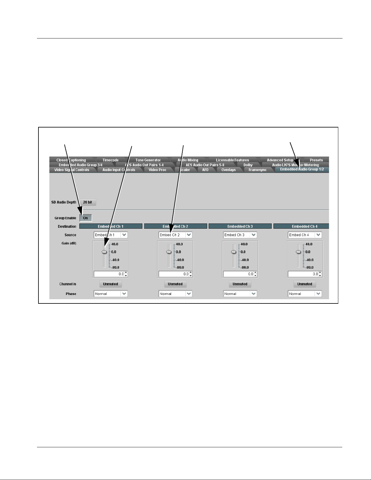
Provides the following Video Proc parametric controls.
• Video Proc Video Proc (On/Off) provides master on/off control of all Video Proc
• Reset to Unity Reset to Unity provides unity reset control of all Video Proc functions.
• Luma Gain Adjusts gain percentage applied to Luma (Y channel).
functions.
• W hen set to Off, Video Proc is bypassed.
• W hen set to On, currently displayed parameter settings take effect.
When Confirm is clicked, a Confirm? pop-up appears, requesting
confirmation.
• Click Yes to proceed with the unity reset.
• Click No to reject unity reset.
(0% to 200% range in 0.1% steps; unity = 100%)
Video Proc
• Luma Lift Adj usts lift applied to Luma (Y-channel).
(-100% to 100% range in 0.1% steps; null = 0.0%)
• Color Gain Adjusts gain percentage (saturation)
applied to Chroma (C-channel).
(0% to 200% range in 0.1% steps; unity = 100%)
• Color Phase Adjusts phase angle applied to Chroma.
(-360° to 360° range in 0.1° steps; null = 0°)
• Gang Luma and Color Gain When set to On, changing either the Color Gain or Luma Ga in controls
• Black Hard Clip Applies black hard clip (limiting) at specified percentage.
increases or decreases both the Video and Chroma levels by equal
amounts.
(-6.8% to 50.0%; null = -6.8%)
3-10 9064 PRODUCT MANUAL 9064-OM (V4.1)
Page 41

Operating Instructions 9064 Function Submenu List and Descriptions
Table 3-2 9064 Function Submenu List — continued
(continued)
• White Hard Clip Applies white hard clip (limiting) at specified percentage.
(50.0% to 109.1%; null = 109.1%)
• White Soft Clip Applies white soft clip (limiting) at specified percentage.
(50.0% to 109.1%; null = 109.1%)
• Chroma Saturation Clip Applies chroma saturation clip (limiting) chroma saturation at specified
percentage.
(50.0% to 160.0%; null = 160.0%)
9064-OM (V4.1) 9064 PRODUCT MANUAL 3-11
Page 42
3 9064 Function Submenu List and Descriptions
Table 3-2 9064 Function Submenu List — continued
Provides video format down-conversions and aspect
ratio controls.
Note: Scaling and/or format conversion removes ATC packets (if present). If ATC packets are present, use the AFD,
Timecode, and Closed Captioning functions described in this manual to preserve and re-apply packets on the output
SDI.
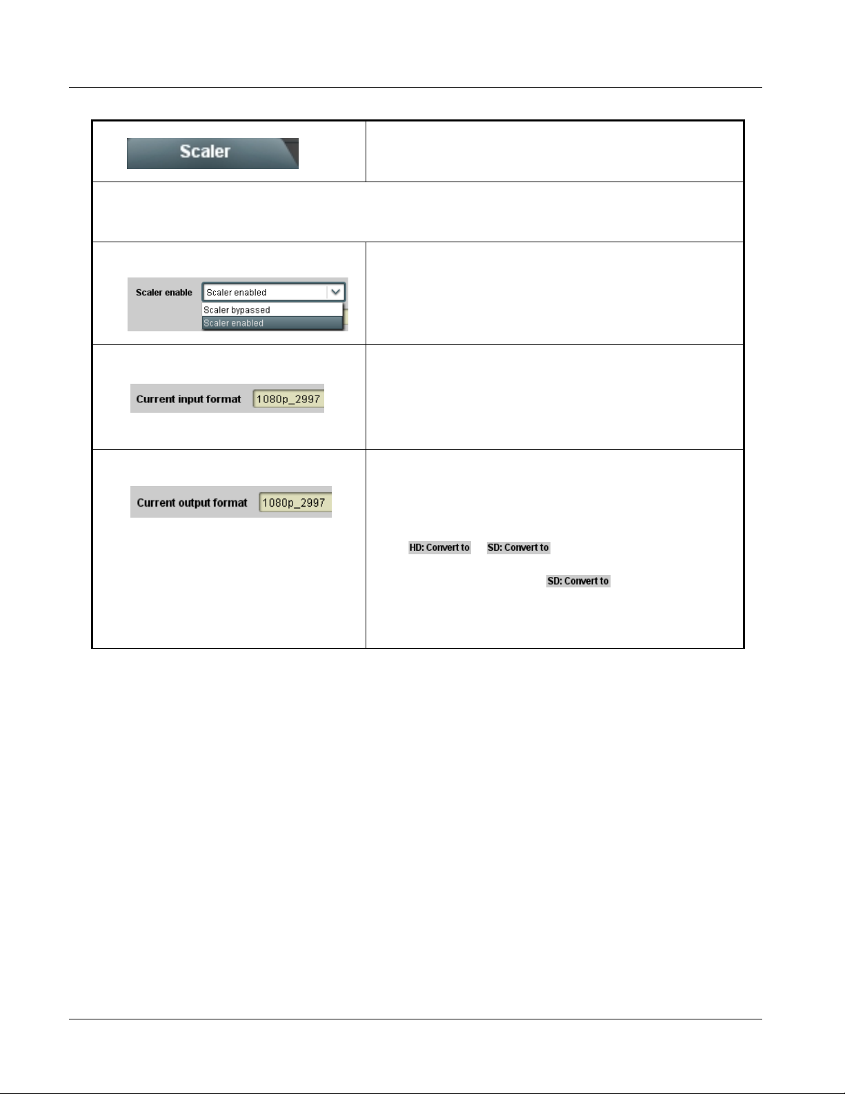
• Scaler enable Enables or bypasses Scaler function as follows:
• Enabled: Provides Scaler functions for the received video input.
• Bypassed: Received video input bypasses the Scaler functions.
Scaler
• Current Input Format Displays the input format of the video currently being received by the 9064
(for example, 1080p at 29.97 Hz frame rate as shown here).
Note: Rates displayed for progressive formats are frame rates; rates
displayed for interlaced formats are field rates.
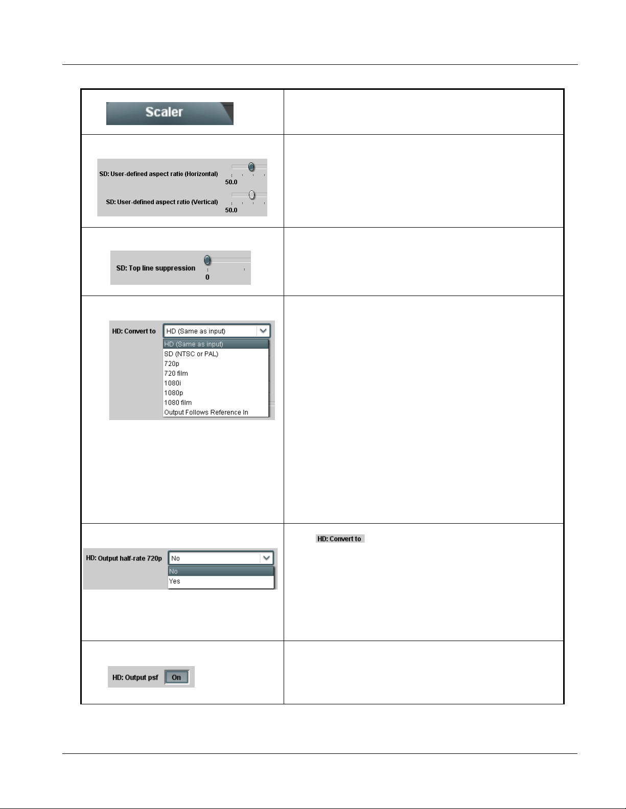
Current Input Format
• Current Output Format Displays the currently selected output format of the video currently being
processed by the 9064 (for example, 1080p at 29.97 Hz frame rate as
shown here). The output format displayed is the output present on the
card’s SDI OUT BNC connectors.
Current Output Format
Note: Output format shown in this display tracks with selection made in
display only tracks with changes applicable to the currently
received input format (for example, when currently receiving HD
video, changes made in the drop-down list have no
effect on the Output Format display). Output form a t al so tracks
with any applicable Scaler functions that affect output format.
Note: Rates displayed for progressive formats are frame rates; rates
displayed for interlaced formats are field rates.
or drop-down lists. Output Format
3-12 9064 PRODUCT MANUAL 9064-OM (V4.1)
Page 43

Operating Instructions 9064 Function Submenu List and Descriptions
Table 3-2 9064 Function Submenu List — continued
Scaler Video Format Conversions
(continued)
Scaler Video Format Conversions
Scaler Video Format Conversions
The Scaler HD: Convert to: a nd SD: Conver t to: drop-down lists (as shown and de scribed in
the following pages) allows selec tion of up/d own/cr oss-con versio n (or no conver sion) fo r variou s
input formats. The table below lists the conversion choices available for various input formats and
frame rates provided by the Scaler Convert to: function. Also shown are the resulting frame
rates for the converted outputs.
Input
Format
525i 59.94 525i 59.94 720p 59.94 720p 29.97 720p 23.98
SD
(NTSC/
PAL)
720p
720p
half-rate
720p
(film rates)
(4)
1080i 1080p
1080p
(film rates)
1080i 59.94 1080p 29.97 1080p 23.98
(4)
1080PsF
(film rates)
1080PsF 23.98
(4)
625i 50 625i 50 720p 50 720p 25 X 1080i 50 1080p 25 X X
720p 60 X 720p 60 720p 30 720p 24
720p 59.94 525i 59.94 720p 59.94 720p 29.97 720p 23.98
1080i 60 1080p 30 1080p 24
(4)
1080i 59.94 1080p 29.97 1080p 23.98
(4)
(4)
1080PsF 24
(4)
1080PsF 23.98
(4)
(4)
720p 50 625i 50 720p 50 720p 25 X 1080i 50 1080p 25 X X
720p 30 X 720p 60 720p 30 720p 24
720p 29.97 525i 59.94 720p 59.94 720p 29.97 720p 23.98
1080i 60 1080p 30 1080p 24
(5)
1080i 59.94 1080p 29.97 1080p 23.98
(5)
(5)
1080PsF 24
(5)
1080PsF 23.98
(5)
(5)
720p 25 625i 50 720p 50 720p 25 X 1080i 50 1080p 25 X X
720p 24 X 720p 60 720p 30 720p 24 1080i 60 1080p 30 1080p 24 1080PsF 24
720p 23.98 525i 59.94 720p 59.94 720p 29.97 720p 23.98 1080i 59.94 1080p 29.97 1080p 23.98 1080PsF 23.98
1080i 60 X 720p 60 720p 30 720p 24
1080i 59.94 525i 59.94 720p 59.94 720p 29.97 720p 23.98
1080i 60 1080p 30 1080p 24
(4)
1080i 59.94 1080p 29.97 1080p 23.98
(4)
(4)
1080PsF 24
(4)
1080PsF 23.98
(4)
(4)
1080i 50 625i 50 720p 50 720p 25 X 1080i 50 1080p 25 X X
1080p 30 X 720p 60 720p 30 720p 24
1080p 29.97 525i 59.94 720p 59.94 720p 29.97 720p 23.98
1080i 60 1080p 30 1080p 24
(5)
1080i 59.94 1080p 29.97 1080p 23.98
(5)
(5)
1080PsF 24
(5)
1080PsF 23.98
(5)
(5)
1080p 25 625i 50 720p 50 720p 25 X 1080i 50 1080p 25 X X
1080p 24 X 720p 60 720p 30 720p 24 1080i 60 1080p 30 1080p 24 1080PsF 24
1080p 23.98 525i 59.94 720p 59.94 720p 29.97 720p 23.98 1080i 59.94 1080p 29.97 1080p 23.98 1080PsF 23.98
1080PsF 24 X 720p 60 720p 30 720p 24 1080i 60 1080p 30 1080p 24 1080PsF 24
1080PsF 23.98 525i 59.94 720p 59.94 720p 29.97 720p 23.98 1080i 59.94 1080p 29.97 1080p 23.98 1080PsF 23.98
Notes:1. The drop-down list choice of “Same as Input” is used when no conversion is desired. For clarity, it is not redundantly
listed here.
2. “X” denotes conversions not available or invalid conversions.
3. Interlaced formats rates listed are field rates. Progressive format rates listed are frame rates.
4. If the original material does not have a proper 3-2 cadence suitable for conversion to film rates, the conversion
reverts to standard de-interlacing. While this video can be converted to film rates, the resulting image motion will
lack smoothness. Therefore, make certain interlaced video is appropriately constructed for 3-2 reverse pulldown
when converting video to film rates. (See 3-2 Pulldown Conversion and Considerations (p. 1-11) for more
information.)
5. Formats using a 30/29.97 Hz progressive frame rate can be converted to a 24/23.98 Hz progressive frame rate,
however some image motion irregularity will appear in the converted output.
9064-OM (V4.1) 9064 PRODUCT MANUAL 3-13
Page 44
3 9064 Function Submenu List and Descriptions
Table 3-2 9064 Function Submenu List — continued
(continued)
Note: SD: controls described below affect SD inputs; HD: controls described below affect HD inputs.
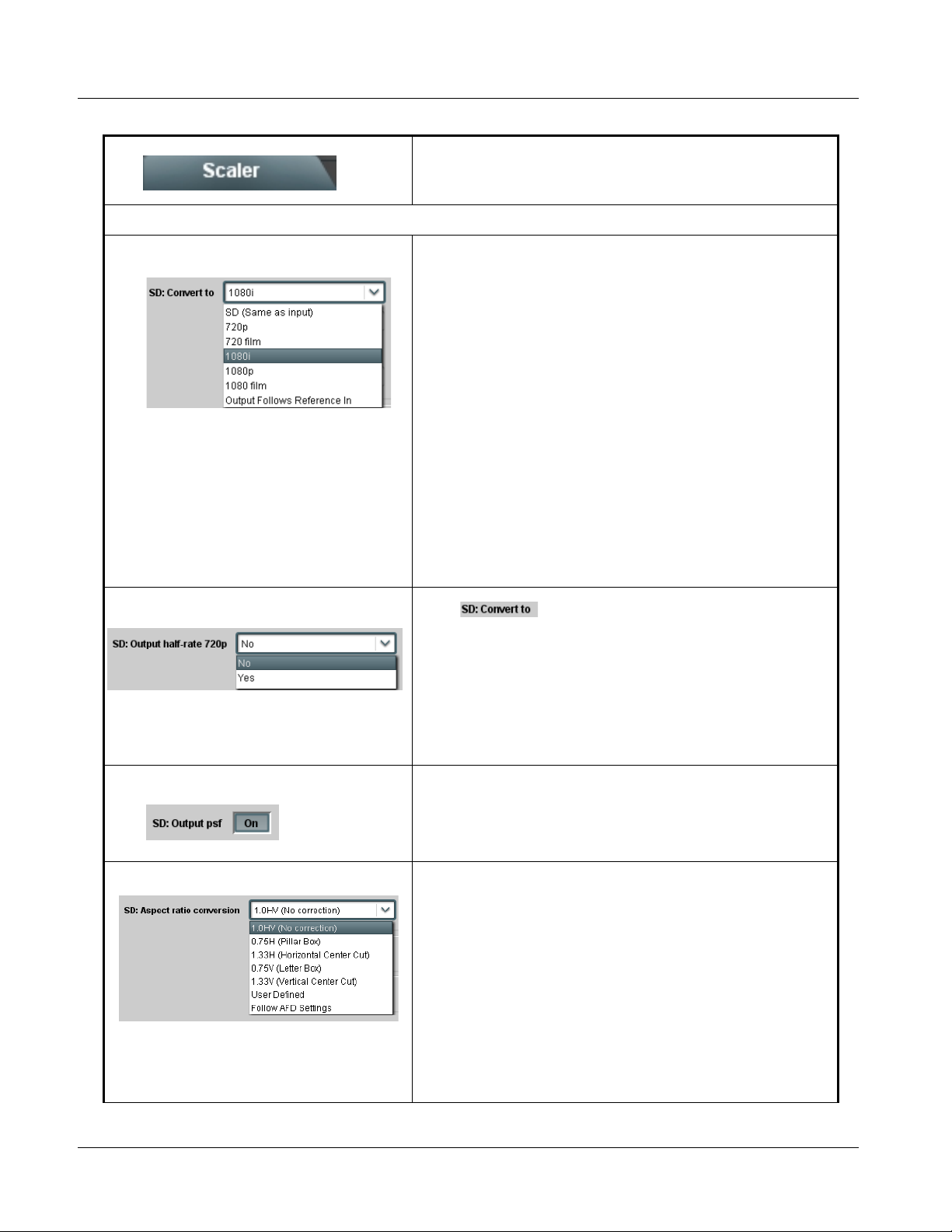
• SD: Convert To When SD video input is received by the 9064, provides output format
conversions, or re-aspecting to SD when SD is the detected input format
as described below.
• SD (Same as input): Output follows currently received video input
format, with Current Input Format and Current Output Format
displays showing same selection.
• 720p: Output is converted to 720p
• 720 film: Output is converted to corresponding 720p film frame rate
• 1080i: Output is converted to 1080i
• 1080p: Output is converted to 1080p
• 1080 film: Output is converted to corresponding 1080i film
frame rate
• Output Follows Reference In: Output tracks with format set in
Reference Video Input
Note: Output Follows Reference In selection automatically sets
the output format to that of the received reference signal
input (this signal is distributed to the 9064 and other cards
via an 8320 frame bus). In addition to extracting a frame
sync and rate, this function determines the type of black
burst (i.e., black burst or tri-level) and sets the output
format to match.
SD: Convert To
• SD: Output Half-rate 720p When drop-down list is set to 720p, converts output to
720p half-rate.
Yes/No control functions as follows:
• No: Do not apply half-rate; leave output at standard frame rate
• Yes: Output set at half- rate
Note: Half-rate outputs are available for the 720p frame rates listed under
“720p” in the “Scaler Video Format Conversions” table on the
previous page.
• SD: Output PsF When enabled (and with the output video is set to 1080 film), converts the
• SD: Aspect Ratio Conversion Selects between the standard preset Aspect Ratio Conversions (ARC)
output to1080PsF (segmented frame progressive).
shown here, as well as User Defined and Follow AFD Settings.
• User Defined settings allow custom user-defined H and V aspect
ratio control.
• Follow AFD Settings sets the output aspect ratio to track with AFD
settings performed in AFD (p. 3-17).
Note: This function is intended for aspect ratio adjustment of a particular
signal without AFD considerations.
• If ARC is being used on a case-by-case basis for a particular
signal, it is easier to use the Scaler ARC tools described here.
• If AFD is to be used to set and apply a standard AFD code label
for ARC, use Follow AFD Settings. Do not perform ARC here;
instead, perform ARC as described in the AFD function
description on page 3-17.
3-14 9064 PRODUCT MANUAL 9064-OM (V4.1)
Page 45
Operating Instructions 9064 Function Submenu List and Descriptions
Table 3-2 9064 Function Submenu List — continued
(continued)
• SD: User-defined aspect ratio ( Horizo ntal) and (Vertical) controls adjust horizontal and vertical zoom
• SD: Top line suppression Selects the number of lines suppressed at the beginning of video. In this
• HD: Convert To When HD video input is received by the 9064, provides output format
percentage. Settings less than (<) 100% provide zoom-out; settings
greater than (>) 100% provide zoom-in.
(50% to 200% range in 0.1% steps; null = 100.0)
manner, the image is scaled proportionally to replace the top few lines
suppressed using this control. Using this control can hide unwanted
closed caption or timecode data.
(Range is 0 thru 10 lines.)
conversions listed below.
• HD (Same as input): Output follows currently received video input
format, with Current Input Format and Current Output Format
displays showing same selection.
• SD (NTSC or PA L): Output is converted to 525i at 59.94 Hz frame
rate or 625i at 50 Hz rate, as applicable.
• 720p: Output is converted to 720p
• 720 film: Output is converted to corresponding 720p film frame rate
• 1080i: Output is converted to 1080i
• 1080p: Output is converted to 1080p
• 1080 film: Output is converted to corresponding 1080i film
frame rate
• Output Follows Reference In: Output tracks with format set in
Reference Video Input
Note: Output Follows Reference In selection automatically sets
the output format to that of the received reference signal input
(this signal is distributed to the 9064 and other cards via an
8320 frame bus). In addition to extracting a frame sync and
rate, this function determines the type of black burst (i.e.,
HD: Convert To
black burst or tri-level) and sets the output format to match.
• HD: Output Half-rate 720p When drop-down list is set to 720p, converts output to 720p
• HD: Output PsF When enabled (and with the output video is set to 1080 film) converts
9064-OM (V4.1) 9064 PRODUCT MANUAL 3-15
half-rate.
Yes/No control functions as follows:
• No: Do not apply half-rate; leave output at standard frame rate
• Yes: Output set at half-rate
Note: Half-rate outputs are available for the 720p frame rates listed under
“720p” in the “Scaler Video Format Conversions” table on page
3-13.
output to 1080PsF (segmented frame progressive).
Page 46

3 9064 Function Submenu List and Descriptions
Table 3-2 9064 Function Submenu List — continued
(continued)
• HD: Aspect Ratio Conversion Selects between the standard preset Aspect Ratio Conversions (ARC)
• HD: User-defined aspect ratio (Horizontal) and (Vertical) controls adjust horizontal and vertical zoom
• HD: Top line suppression Selects the number of lines suppressed at the beginning of video. In this
shown here, as well as User Defined and Follow AFD Settings.
• User Defined settings allow custom user-defined H and V aspect
ratio control.
• Follow AFD Settings sets the output aspect ratio to track with AFD
settings performed in AFD (p. 3-17).
Note: This function is intended for aspect ratio adjustment of a particular
signal without AFD considerations.
• If ARC is being used on a case-by-case basis for a particular
signal, it is easier to use the Scaler ARC tools described here.
• If AFD is to be used to set and apply a standard AFD code label
for ARC, use Follow AFD Settings. Do not perform ARC here;
instead, perform ARC as described in the AFD function
description on page 3-17.
percentage. Settings less than (<) 100% provide zoom-out; settings
greater than (>) 100% provide zoom-in.
(50% to 200% range in 0.1% steps; null = 100.0)
manner, the image is scaled proportionally to replace the top few lines
suppressed using this control. Using this control can hide unwanted
closed caption or timecode data.
(Range is 0 thru 10 lines.)
• Detail Enhancement Controls Sharpness Level, Threshold, and Noise Reduction controls (individually
• S h arpness Level Control Adjusts the aggressiveness of sharpening applied to MPEG video.
• S h arpness Threshold Control Adjusts the point at which sharpening rules become active. Data below
• Noise Reduction Control Adjusts the amount of statistical low-pass filtering applied to the data.
described below) which can be used to tailor output video sharpness per
program material and aesthetic preferences.
Note: Detail enhancement controls apply to both SD and HD inputs.
Optimum setting results in overall perception of increased sharpness,
while avoiding pattern noise artifacts.
(Range is 0 thru 255)
the threshold setting is passed unaffected.
Higher settings allow for a more subtle sharpness enhancement
(especially with content showing motion). Lower settings allow more
content in general to be acted upon by the enhancement process.
(Range is 0 thru 255)
Using this control, regular pattern noise artifacts from the sharpening
process can be reduced, resulting in subjectively smoother raster
backgrounds and detail boundaries.
(Range is 0 thru 63)
3-16 9064 PRODUCT MANUAL 9064-OM (V4.1)
Page 47
Operating Instructions 9064 Function Submenu List and Descriptions
Table 3-2 9064 Function Submenu List — continued
Allows assignment of AFD (Active Format Description)
codes to the SDI output video, and allows unique ARC
AFD
Without AFD
settings to be applied for each AFD code.
When an appropriate AFD code is received by this card,
this function can be used to apply the AFD-directed
re-aspecting, resulting in a properly scaled and cropped
image area.
NTSC-Coded
(4:3) 1080i
Video Signal
NTSC-Coded
image on 16:9
display shows
letterbox cropping
With AFD
NTSC-Coded
(4:3) 1080i
Video Signal
with 1010
AFD Code
NTSC-Coded
image on 16:9
display shows
letterbox cropping
9064 with 1010
AFD Code
Received and
Applied
Up-Conversion
to 16:9
Uncorrected
up-conversion
results in “postage
stamp” effect with
both letterbox and
sidebars visible on
16:9 display
Up-Conversion
to 16:9
AFD Corrected
up-conversion
results in intended
image area
properly visible on
16:9 display
1080i Video Signal
with 16:9
uncorrected signal
1080i Video Signal
with 16:9
corrected signal
9064-OM (V4.1) 9064 PRODUCT MANUAL 3-17
Page 48

3 9064 Function Submenu List and Descriptions
Table 3-2 9064 Function Submenu List — continued
(continued)
• Incoming AFD Displays incoming AFD setting as follows:
• If AFD code is present, one of the 1 1, four-bit AFD codes is displayed (as
shown in the example to the left). Also displayed is the VANC line
number of the incoming AFD code.
• I f no AFD setting is present in the video signal, No AFD Present is
displayed.
AFD
• 16:9 Controls Individual user (custom) H Zoom, V Zoom, and AFD Output Code tools
for the following 12 AFD codes/formats suited for 16:9 sources:
AFD Code
•
•
•
1: AFD codes numbering and definitions conform to SMPTE 2016-1-2007.
2: Image Prot ecte d impl ies pictu re cont ent that must not be cropped by
(1)
Description AFD Code
– No code present 1001 4:3 (center)
0000 Undefined 1010
0010 Full frame 1011 14:9 (center)
0011 4:3 (center) 1101
0100
1000 Full frame 1111
conversion processes or display devices. Alternate center formats may
have protected center areas, with areas outside of the protected area not
containing mandatory content. Refer to SMPTE 2016-1-2007 for more
information if needed.
Box > 16:9
(center)
1110
(1)
4:3 (with alternate
16:9 (with alternate
14:9 center)
16:9 (with alternate
4:3 center)
Description
16:9 (image
protected)
14:9 center )
(2)
(2)
(2)
• 4:3 Controls Individual user (custom) H Zoom, V Zoom, and AFD Output Code tools
for the following 12 AFD codes/formats suited for 4:3 sources:
AFD Code
•
•
•
1: AFD codes numbering and definitions conform to SMPTE 2016-1-2007.
2: Image Protected implies picture content that must not be cropped by
(1)
Description AFD Code
– No code present 1001 Full frame
0000 Undefined 1010 16:9 (center)
0010 Box 16:9 (top) 1011 14:9 (cen ter )
0011 Box 14:9 (top) 1101 4:3 (with alternate
0100 Box > 16:9
1000 Full frame 1111 16:9 (with alternate
conversion processes or display devices. Alternate center formats may
have protected center areas, with areas outside of the protected area not
containing mandatory content. Refer to SMPTE 2016-1-2007 for more
information if needed.
(center)
(1)
1110 16:9 (with alternate
Description
14:9 center)
14:9 center )
4:3 center)
(2)
(2)
3-18 9064 PRODUCT MANUAL 9064-OM (V4.1)
Page 49
Operating Instructions 9064 Function Submenu List and Descriptions
Table 3-2 9064 Function Submenu List — continued
(continued)
• H Zoom and V Zoom Controls Individual H Zoom and V Zoom controls for each of the 12 AFD code
• AFD Output Code Twelve drop-down lists that allow assignment of AFD codes to the 12
choices for both 4:3 and 16:9 coded input frames described above allow
adjustment of horizontal and vertical zoom percentage for each AFD
code.
(50% to 200% range in 0.1% steps)
Note: To apply H and V settings for a given AFD code using this card,
Scaler Aspect Ratio Conversion must be set to Follow AFD
Settings.
Note: Default zoom percentages use the following rules:
• The default zoom percentages displayed when this function is
accessed are the default percentages corresponding to the
respective AFD standard ratio definitions (for example, default
horizontal and vertical zoom percentages for 4:3 ratios are
correspondingly 133% and 100%, yielding a 4:3 aspect ratio). In
these cases, the null values for this definition are the default values
shown.
• In cases where a different aspect ratio is to be used for a given
received aspect ratio, the default ratio displayed is the null value
that results (assuming no H or V zoom modification). For example,
for a 16:9 signal and settings set for a 1111 (15) AFD code (“16:9
with 4:3 protected image”), the respective displayed default H and V
zoom settings of 100% and 75% protect the Protected Image Area.
individual H Zoom and V Zoom tools described above.
Note: • The default AFD codes displayed when this function is accessed
show the SMPTE AFD code most closely reflecting the aspect
ratio when the corresponding default settings are applied.
• An AFD Output Code setting has no effect on aspect on ARC
performed by this card; it merely applies a selected AFD code to
the output video.
•
•
•
In this example, if a “0011” AFD code is received, the entered
H Zoom and V Zoom values corresponding to AFD code 0011
are applied to the image (133.0% and 100.0%, respectively, in
this example). The H Zoom and V Zoom values for any AFD code
can be changed as desired. When the card Scaler Aspect Ratio
Conversion is set to Follow AFD Settings, the H and V zoom
values set here are applied to the output video.
9064-OM (V4.1) 9064 PRODUCT MANUAL 3-19
In this example, with the AFD Output Code
drop-down set to 1000, if a 0011 code is received
on the input, an AFD code of 1000 is ouputted by
the card. (Note that the assigned output code has
no effect on ARC performed within this card.)
Page 50
3 9064 Function Submenu List and Descriptions
Table 3-2 9064 Function Submenu List — continued
(continued)
• Output Line Allows selecting the line location of the AFD data within the video signal
• Restore Defaults Restore Defaults provides default restore of all user settings described in
Ancillary Data space.
(Range is 9 thru 41)
Note: • Although the output line drop-down will allow any choice within the
9 thru 41 range, the actual range is automatically clamped (limited)
to certain ranges to prevent inadvertent conflict with active picture
area depending on video format. See Ancillary Data Line Number
Locations and Ranges (p. 3-8) for more information.
• The card does not check for conflicts on a given line number.
Make certain the selected line is available and carrying no other
data.
the remainder of the AFD function description.
When Confirm is clicked, a Confirm? pop-up appears, requesting
confirmation.
• Click Yes to proceed with restore defaults.
• Click No to reject restore defaults.
3-20 9064 PRODUCT MANUAL 9064-OM (V4.1)
Page 51

Operating Instructions 9064 Function Submenu List and Descriptions
Table 3-2 9064 Function Submenu List — continued
Allows Safe Action and/or Safe Title overlays to be
added to the image. The overlays can be used to
identify safe action and safe title areas within the image.
Note: Overlay markers using this function are for setup only. When enabled, these markers are embedded in the SDI video
output signal and may appear in the image. Use this function only on preview video and not on-air video. Make certain
any overlay tools are turned off when done.
Note: Multiple overlay markers described below can be simultaneously enabled as desired.
• Safe Action Area
When enabled (On), turns on the Safe Action Area overlay.
Overlays
When enabled (On), outline shows Safe Action Area boundary.
Color of boundary is selected using Color drop-down list.
• Safe Title Area When enabled (On), turns on the Safe Title Area overlay.
OVERLAY_SAFACT1.0.PNG
OVERLAY_SAFTLE1.0.PNG
When enabled (On), outline shows Safe Title Area boundary. Color
of boundary is selected using Color drop-down list.
9064-OM (V4.1) 9064 PRODUCT MANUAL 3-21
Page 52

3 9064 Function Submenu List and Descriptions
Table 3-2 9064 Function Submenu List — continued
(continued)
• Safe Action/Title Area Color Selects the Safe Action and Safe Title overlay color from choices shown
• 0.75H Safe Action Area When enabled (On), turns on the 0.75H Safe Action Area overlay that
to the left.
shows the 4:3 safe area on a 16:9 image (i.e., the resulting safe area
when the image is converted to 4:3).
OVERLAY_SAFACT_NORMW075.PNG
Outline shows 0.75H Safe Action Area boundary. Color of boundary
is selected using Color drop-down list.
Note: If 0.75H (Pillar Box) is selected using the Aspect Ratio Conversion
tool in the Scaler function, and Overlays Follow ARC is selected
for this function, the overlays will be additionally reduced 0.75H
beyond the standard 4:3 safe areas
3-22 9064 PRODUCT MANUAL 9064-OM (V4.1)
Page 53

Operating Instructions 9064 Function Submenu List and Descriptions
Table 3-2 9064 Function Submenu List — continued
(continued)
• 0.75H Safe Title Area When enabled (On), turns on the 0.75H Safe Title Area overlay that
• 0.75H Safe Action/Title Area Color Selects the 0.75H Safe Action and 0.75H Safe Title overlay color from
shows the 4:3 safe title area on a 16:9 image (i.e., resulting safe title area
when the image is converted to 4:3).
OVERLAY_SAFTLENORMW075.PNG
Outline shows 0.75H Safe Title Area boundary. Color of boundary
is selected using Color drop-down list.
Note: If 0.75H (Pillar Box) is selected using the Aspect Ratio Conversion
tool in the Scaler function, and Overlays Follow ARC is selected
for this function, the overlays will be additionally reduced 0.75H
beyond the standard 4:3 safe areas
choices shown to the left.
9064-OM (V4.1) 9064 PRODUCT MANUAL 3-23
Page 54

3 9064 Function Submenu List and Descriptions
Table 3-2 9064 Function Submenu List — continued
(continued)
• Center Cross When enabled (On), turns on the Center Cross overlay.
OVERLAY_CTRX.PNG
Color of marker is selected using Color drop-down list.
• Center Cross Color Selects the Center Cross overlay color from choices shown to the left.
• Overlays Follow ARC When enabled (On), overlays are resized along with the image in
accordance with any ARC settings.
Note: This choice functions only when a zoom-out is applied (settings
less than 100%).
3-24 9064 PRODUCT MANUAL 9064-OM (V4.1)
Page 55

Operating Instructions 9064 Function Submenu List and Descriptions
Table 3-2 9064 Function Submenu List — continued
Provides color corrector functions for the individual RGB
channels of the received SD/HD SDI signal.
• Color Corrector Color Corrector (On/Off) provides master on/off control of all Color
• Reset to Unity Reset to Unity provides unity reset control of all Color Corrector
• Black Adj. (Green – Red – Blue) Separate red, green, and blue black level controls respectively apply lift
Corrector functions.
• When set to Off, all processing is bypassed.
• When set to On, currently displayed parameters settings take effect.
functions.
When Confirm is clicked, a Confirm? pop-up appears, requesting
confirmation.
• Click Yes to proceed with the unity reset.
• Click No to reject unity reset.
value for R, G, and B channels.
(-100.0 to 100.0% range in 0.1% steps; null = 0.0)
Color Correction
• Gang Black Level Controls When set to On, changing any of the Black Adj. controls increases or
decreases R, G, and B black levels by equal amounts.
• White Adj. (Green – Red – Blue) Separate red, green, and blue gain controls respectively apply gain
• Gang White Level Controls When set to On, changing any of the White Adj. (gain) controls increases
9064-OM (V4.1) 9064 PRODUCT MANUAL 3-25
percentage for R, G, and B channels.
(0.0 to 200.0% range in 0.1% steps; unity = 100.0)
or decreases R, G, and B white gain levels by equal amounts.
Page 56

3 9064 Function Submenu List and Descriptions
Table 3-2 9064 Function Submenu List — continued
(continued)
• Gamma (Green – Red – Blue) Separate red, green, and blue gamma controls respectively apply gamma
• Gang Gamma Controls When set to On, changing any of the Gamm a controls increases or
curve adjustment for R, G, and B channels.
(0.125 to 8.000 range in thousandths steps; unity = 1.000)
decreases all Gamma settings by equal amounts.
3-26 9064 PRODUCT MANUAL 9064-OM (V4.1)
Page 57

Operating Instructions 9064 Function Submenu List and Descriptions
Table 3-2 9064 Function Submenu List — continued
Provides video Frame Sync and delay control tools.
Framesync
• Framesync Enable Disables the Frame Sync function, or selects from choices below.
• Off: Video path bypasses frame sync entirely; output video timing
tracks with input video timing.
• Reference 1: Allows Frame Sync function to use external
Reference 1 as the reference (“house”) standard.
• Reference 2: Allows Frame Sync function to use external
Reference 2 as the reference (“house”) standard.
Note: If Reference 1 or Reference 2 is selected and an
appropriate external reference is not received, the
status portion of DashBoard™, indicating invalid frame sync
reference error. (Additionally, the card edge ERR indicator
illuminates indicating the same.) External reference signals
Reference 1 and Reference 2 are distributed to the card
and other cards via a frame bus.
• Input Video: Allows full framesync functionality (such as delay
offset), but instead uses the input video signal as the reference
standard.
Note: If Input Video is used for framesync, any timing instability
on the input video will result in corresponding instability on
the output video. This setting should only be used where
syncing to input video is known to be reliable.
indication appears in the Card Info
• Vertical Delay Control When Framesync is enabled, sets vertical delay (in number of lines of
• Horizontal Delay Control When Framesync is enabled, sets (in µsec of output video timing)
output video/format) between the output video and the frame sync
reference.
(Range is -1124 thru 1124 lines.)
Note: Lines refer to lines in the output video format, and not to the
reference format.
horizontal delay between the output video and the frame sync reference.
(Range is -64.000 thru 64.000 µsec)
Note: When an external framesync reference is used, the card will not
produce a framesync reset until the variance between framesync
reference and output video exceeds ± 2 clock periods. Therefore, a
framesync reset will not result if offsets within this window are
applied.
To apply an offset/framesync reset within this window, first apply a
relatively large offset, then apply the target smaller offset.
Example: T o apply a 1-period offset, first apply a 10-period positive
offset and then apply a 9-period negative offset. This results in the
target 1-period offset being applied to the output video.
9064-OM (V4.1) 9064 PRODUCT MANUAL 3-27
Page 58
3 9064 Function Submenu List and Descriptions
Table 3-2 9064 Function Submenu List — continued
(continued)
• Minimum Latency Frames Control
Minimum Latency Frames Control
• Video Delay Display Displays the current input-to-output video delay (in msec units) as well as
When Framesync is enabled, specifies the smallest amount of latency
allowed by the frame sync (latency measurement in output video frames).
The frame sync will not output a frame unless the specified number of
frames are captured in the buffer. The operational latency of the frame
sync is always between the specified minimum latency and
minimum latency plus one fra m e (not one field).
(Maximum range is 0 to 13.)
Note: Due to card memory limits, the maximum available Minimum
Latency Frames is related to the output video format selected.
For example, with a 1080i59.94 output, the maximum allowed
setting is 5. For a 1080i film (23.98) output, the maximum allowed
setting is 3. Conversely, greater maximum settings are allowed for
SD formats such as 525i59.94, where the practical maximum limit
is 13.
When using this control, be sure to check the Framesync Status
display as follows:
• Latency frames selection within limits.
• Latency frames selection exceeds limits.
in terms of Frames/fractional frame (in number of lines).
• Framesync Status Display Displays the current framesync status as follows:
• Framesync status OK.
• Framesync Enable set to Off.
• I mpr oper or missing framesy nc refere nce.
• Latency frames selection exceeds limits.
Note: See Minimum Latency Frames Control ( p. 3-28) for more
information about this message.
• Loss of Input Signal Selection In the event of input video Loss of Signal (LOS), determines action to be
taken as follows:
• Disable Outputs: Disab le all outputs.
• Freeze Last Frame: Freeze image to last good frame (last frame
having valid SAV and EAV codes).
• Freeze to Color: Freeze image to a color raster (as selected using
Framesync LOS Freeze Color control).
Note: If LOS is set to Freeze to Last Frame, there will be audio noise
of last audio pacekt also frozen. If card is to handle any audio,
be aware of this if LOC is anticipated in OTA chain.
3-28 9064 PRODUCT MANUAL 9064-OM (V4.1)
Page 59

Operating Instructions 9064 Function Submenu List and Descriptions
Table 3-2 9064 Function Submenu List — continued
(continued)
• Framesync LOS Freeze Color In the event of LOS with Freeze to Color enabled above, sets the image
• Custom Color Hue Adjusts raster hue (phase angle) for custom LOS color.
• Custom Color Saturation Adjusts raster saturation level for custom LOS color.
raster color from choices shown to the left.
(-360° to 360° range in 0.1° steps; null = 0°)
(0% to 100% range in 0.1% steps)
• Custom Color Y Level Adjusts raster luma level for custom LOS color.
(64 to 940 range)
• Reset Framesync
Reset Framesync
Resets the frame sync, clearing any buffered video.
When Confirm is clicked, a Confirm? pop-up appears, requesting
confirmation.
• Click Yes to reset the frame sync.
• Click No to reject reset.
9064-OM (V4.1) 9064 PRODUCT MANUAL 3-29
Page 60
3 9064 Function Submenu List and Descriptions
Table 3-2 9064 Function Submenu List — continued
Provides support for closed captioning setup.
Note: When receiving HD-SDI, both CEA 608 and CEA 708 are supported, with CEA 608 and CEA 708 (containing CEA 608
packets) converted to line 21 closed captioning on outputs down-converted to SD (on up-convert of SD, only CEA 608
closed captioning is generated).
• Closed Captioning On/Off Turns on or turns off the Closed Captioning output.
Note: • When set to On, closed captioning is set to standard default line
number. See Ancillary Data Line Number Locations and Ranges
(p. 3-8).
• The card does not check for conflicts on a given line number.
Make certain the selected line is available and carrying no other
data.
• Closed captioning line may contain active unintended data even if
closed captioning is set to Off. If closed captioning is not to be
used, it is recommended to use the Top Line Suppression
control to eliminate the possibility of this unintended data from
appearing in the active video area.
(See Scaler tab (p. 3-12) Top line suppression control for more
details.)
Closed Captioning
• Closed Captioning Input Status Displays incoming Closed Captioning status as follows:
• If closed captioning is present, a message similar to the example shown
left is displayed. Also displayed is the VANC line number of the incoming
closed captioning packet (or SD waveform-based VANC line number).
• I f no closed captioning is present in the video signal, Not Present or
Disabled is displayed.
Note: • Pa cket closed captioning status Captioning Rejected Due To
message can appear due to the items described below. The
closed captioning function assesses cdp_identifier,
cdp_frame_rate, ccdata_present, and caption_service_active
items contained in the packet header to make the determinations
listed below. Refer to CEA-708-B for more information.
Message Description
Unsupported Frame Rate F ilm rate closed -captioning
Data Not Present Packet is marked from closed
No Data ID Packet from closed captioning
• caption service is marked as inactive display indicates bit in
packet from upstream source may inadvertently be set as
inactive. In this case, closed captioning data (if present) is still
processed and passed by the card as normal.
• The closed captioning function does not support PAL closed
captioning standards.
• Closed Captioning HD Output Line Selects the VANC line number (9 thru 41) for the closed caption data
when the output is HD.
Note: Although the output line drop-down will allow any choice within the
9 thru 41 range, the actual range is automatically clamped (limited
to) certain ranges to prevent inadvertent conflict with active picture
area depending on video format. See Ancillary Data Line Number
Locations and Ranges (p. 3-8) for more information.
(either as pass-through or up/
down conversion) is not
supported by the card.
captioning source external to the
card that no data is present.
source external to the card is not
properly identified with 0x9669
as the first word of the header
(unidentified packet).
3-30 9064 PRODUCT MANUAL 9064-OM (V4.1)
Page 61
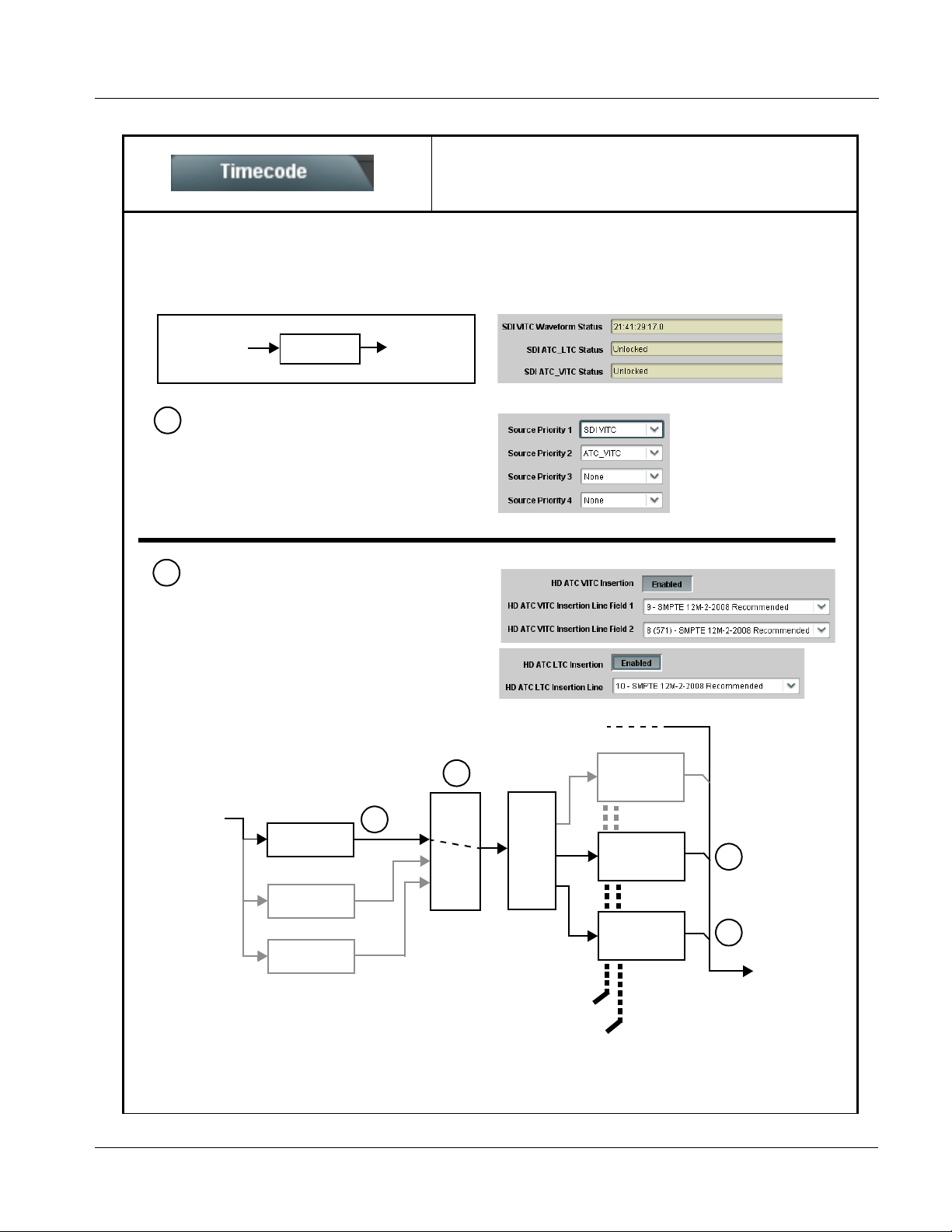
Operating Instructions 9064 Function Submenu List and Descriptions
Table 3-2 9064 Function Submenu List — continued
Provides timecode data extract ion from va rious
sources, and provides formatting and re-insertion
Timecode
Shown below is an example in which received 525i 5994 SDI video is being converted to 720p 5994. To preserve and re-insert
the timecode data, the following can be performed using the Timecode function. Each Timecode control is fully described on
the pages that follow.
controls for inserting the timecode into the output video.
525i 5994
w/ VITC
Waveform
A
Noting that the incoming video contains VITC
9064
720p 5994
w/ ATC_VITC
w/ ATC_LTC
waveform timecode data (as shown in the status
display), set the Source Priority drop-down lists to
include VITC Waveform timecode data (SDI VITC) as
a choice. This extracts VITC Waveform timecode
data from the incoming video.
In this example, it is desired to provide both SDI
B
ATC_VITC and ATC_LTC timecode data in the
converted HD output video. As such, set both
HD ATC VITC Insertion and HD ATC LTC Insertion
to Enabled.
In the example here, the line numbers are set to the
default SMPTE 12M-2-2008 recommended values.
525i SDI
w/ VITC
Waveform
SDI VITC
Detect/Extract
A
A
Priority/
Select
Buffer/
Format
SDI VITC
Timecode
Proc/Embed
ATC_VITC
Timecode
Proc/Embed
B
SDI ATC_VITC
Detect/Extract
ATC_LTC
Timecode
Line
Number
Control
Proc/Embed
ATC_VITC Insertion = Enabled
ATC_LTC Insertion = Enabled
ATC_VITC1 = Line 9 (default SMPTE 12M-2)
ATC_VITC2 = Line 8 (571) (default SMPTE 12M- 2)
ATC_LTC = Line 10 (default SMPTE 12M-2)
SDI ATC_LTC
Detect/Extract
Insert
Control
9064-OM (V4.1) 9064 PRODUCT MANUAL 3-31
B
720p SDI
w/ATC_VITC
w/ATC_LTC
Page 62
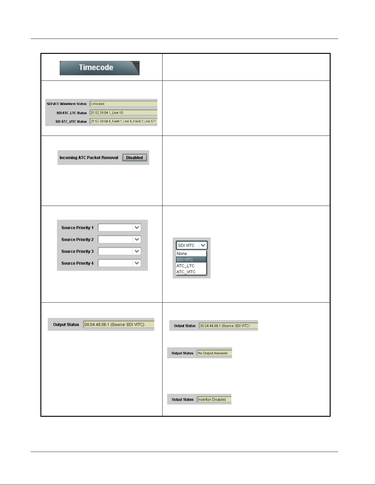
3 9064 Function Submenu List and Descriptions
Table 3-2 9064 Function Submenu List — continued
(continued)
• Timecode Source Status Displays Displays the current status and contents of the four supported timecode
• Incoming ATC Packet Removal Control Enables or disables removal of existing input video ATC timecode packets
• Source Priority As described here, selects the priority assigned to each of the four
formats shown to the left.
• If a format is receiving timecode data, the current content (timecode
running count and line number) is displayed.
• I f a format is not receiving timecode data, Unlocked is displayed.
from the output. This allows removal of undesired existing timecodes from
the output, resulting in a “clean slate” where only desired timecodes are
then re-inserted into the output. (For example, if both SDI ATC_VITC and
ATC_LTC are present on the input video, and only ATC_LTC is desired,
using the Removal control will remove both timecodes from the output.
The ATC_LTC timecode by itself can then be re-inserted on the output
using the other controls discussed here.)
Note: When the Scaler is enabled, ATC packets are automatically
removed. The Timecode function must be used to re-insert the
timecode data into the output video.
supported formats in the event the preferred source is unavailable.
Each of the four Source Priority selection lists allows assignment of
source priority from the following choices:
Source Priority 1 thru Source Priority 4 select the preferred format to be
used in descending order (i.e., Source Priority 2 selects the second-most
preferred format, and so on).
• Output Stat us Dis play Displays the current content and source being used for the timecode data
as follows:
• Output status OK (in this example, running SDI VITC timecode received
and outputted).
• Timecode not available due to lack of appropriate input timecode data on
enabled formats.
Note: Timecode output requires that source and priority are appropriately
selected (as described above in Source Priority). Also, video input
must contain appropriate timecode data.
• Timecode Insertion button set to Disabled; output insertion disabled.
3-32 9064 PRODUCT MANUAL 9064-OM (V4.1)
Page 63

Operating Instructions 9064 Function Submenu List and Descriptions
Table 3-2 9064 Function Submenu List — continued
(continued)
• VITC Waveform Output Line Selects the VITC1 and VITC2 line numbers (6 thru 22) where the VITC
• SD VITC Waveform Insertion Control Enables or disables VITC waveform timecode insertion into the SD-SDI
• SD ATC Insertion Control For SD output, enables or disables ATC_VITC timecode insertion into the
• HD ATC_VITC Insertion Control For HD output, enables or disables AT C_VITC timecode insertion into the
data is inserted.
Note: • Although the output line drop-down will allow any choice within the
6 thru 22 range, the actual range is automatically clamped
(limited) to certain ranges to prevent inadvertent conflict with
active picture area depending on video format. See Ancillary Data
Line Number Locations and Ranges (p. 3-8) for more information.
• The card does not check for conflicts on a given line number.
Make certain the selected line is available and carrying no other
data.
• If only one output line is to be used, set both controls for the same
line number.
output stream.
video stream.
Note: SD ATC_VITC is locked to line 12. The card does not check for
conflicts on a given line number. Make certai n this line is available if
SD ATC_VITC is to be used. See Ancillary Data Line Number
Locations and Ranges (p. 3-8) for more information.
video stream.
• HD ATC_VITC Line Insertion Controls For HD ATC_VITC timecode output, selects the line number for
• HD ATC_LTC Insertion Control For HD output, enables or disables ATC_LTC timecode insertion into the
ATC_VITC1 and ATC_VITC2.
Note: • Although the output line drop-down will allow any choice within the
8 thru 20 range, the actual range is automatically clamped
(limited) to certain ranges to prevent inadvertent conflict with
active picture area depending on video format. See Ancillary Data
Line Number Locations and Ranges (p. 3-8) for more information.
• The card does not check for conflicts on a given line number.
Make certain the selected line is available and carrying no other
data.
• If only one output line is to be used, set both controls for the same
line number.
video stream.
9064-OM (V4.1) 9064 PRODUCT MANUAL 3-33
Page 64
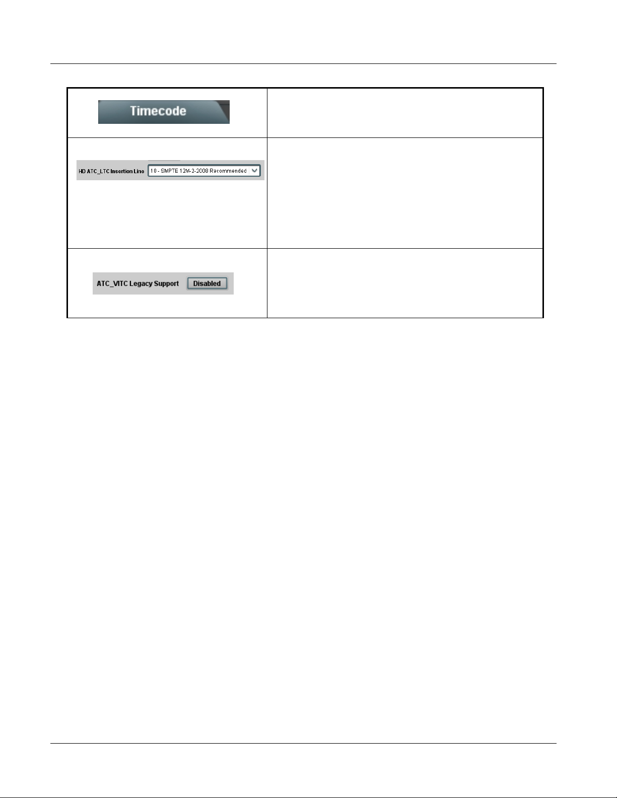
3 9064 Function Submenu List and Descriptions
Table 3-2 9064 Function Submenu List — continued
(continued)
• HD ATC_LTC Line Insertion Control For HD timecode output, selects the line number for ATC_LT C timecode
• ATC_VITC Legacy Support Control When enabled, accommodates equipment requiring ATC_VITC packet in
data.
Note: • Although the output line drop-down will allow any choice within the
9 thru 20 range, the actual range is automatically clamped
(limited) to certain ranges to prevent inadvertent conflict with
active picture area depending on video format. See Ancillary Data
Line Number Locations and Ranges (p. 3-8) for more information.
• The card does not check for conflicts on a given line number.
Make certain the selected line is available and carrying no other
data.
both fields as a “field 1” packet (non-toggling).
Note: Non-toggling VITC1 and VITC2 packets do not conform to
SMPTE 12M-2-2008 preferences. As such, ATC_VITC Legacy
Support should be enabled only if required by downstream
equipment.
3-34 9064 PRODUCT MANUAL 9064-OM (V4.1)
Page 65

Operating Instructions 9064 Function Submenu List and Descriptions
Table 3-2 9064 Function Submenu List — continued
Allows up to 16 card user settings configuration presets
to be saved in a Preset and then recalled (loaded) as
Presets
desired. All current settings (including list selections
and scalar (numeric) control settings such as Gain, etc.)
are saved when a Preset Save is invoked.
The Preset Name field and Preset Save button
allow custom user setting configurations to be
labeled and saved to a Preset for future use.
The Preset Load button and the Selected Preset
drop-down list allow saved presets to be selected
and loaded as desired. When a preset is loaded, it
immediately becomes active with all user settings
now automatically set as directed by the preset.
Saved presets can be uploaded to a computer for
use with other same-model COMPASS™ cards.
Each of the items to the left are described in detail on
the following pages.
• Preset Save and Load • Preset Save stores all current card control settings to the currently
• Selected Preset Selected Preset 1 thru Selected Preset 16 range in drop-down list
•
•
•
selected preset.
(For example, if Preset 1 is selected in the Selected Preset drop-down
list, clicking and confirming Preset Save will then save all current card
control settings to Preset 1)
• Preset Load loads (applies) all card control settings defined by
whatever preset (Preset 1 thru Preset 16) is currently selected in the
Selected Preset drop-down list.
(For example, if Preset 3 is selected in the Selected Preset drop-down
list, clicking and confirming Preset Load will then apply all card control
settings defined in Preset 3)
The above buttons have a Confirm? pop-up that appears, requesting
confirmation.
Note: Applying a change to a preset using the buttons described above
rewrites the previous preset contents with the invoked contents.
Make certain change is desired before confirming preset change.
selects one of 16 stored presets as ready for Save (being written to) or for
Load (being applied to the card).
Note: The preset names shown to the left are the default (unnamed)
preset names. All 16 presets in this case are loaded identically with
the factory default settings.
• Card Name Text entry field provides for optional entry of card name, function, etc. (as
9064-OM (V4.1) 9064 PRODUCT MANUAL 3-35
shown in this example).
Note: Card name can be 31 ASCII characters maximum.
Page 66

3 9064 Function Submenu List and Descriptions
Table 3-2 9064 Function Submenu List — continued
(continued)
• Reset Current Preset • Reset Current Preset resets all parameters (including preset custom
• Preset Name With one of 16 presets selected, provides for entry of custom name for the
• Download Presets Download Presets allows all 16 presets to be stored to a specified location
Download a presets file to a computer on the card’s DashBoard network to save presets. Preset files stored on a computer can
then be uploaded back to the card.
Note also that a presets file can also be uploaded to other same-model COMPASS
using a single card can be easily applied to other same-model cards without repeating the setup work on the other cards.
name entered) of the currently selected Preset (as displayed in the
Selected Preset field) to factory default settings.
The button has a Confirm? pop-up that appears, requesting
confirmation.
preset (as shown in example below).
Entering text in Preset
Name field (in this
example, “RCVR21”)
applies custom name to
selected Preset (in this
example, Preset 2)
Note: • Preset name can be seven ASCII characters maximum.
• The Preset ID number does not need to be entered; it is
added automatically.
on a network computer for use with other same-model COMPASS™
cards.
®
cards. In this manner, presets built up
Download (save) card presets to a
network computer by clicking
Download
Presets – Save
at the bottom of
the Presets
page.
Browse to a desired
save location (in
this example, My
Documents\Cobalt
Presets).
The file can then be
renamed if desired
(RCVR21 Presets
in this example)
before saving.
Upload (open) card presets from a network
computer by clicking Upload
at the bottom of
DashBoard.
Browse to the location
where the file was saved
on the computer or
drive (in this example,
My Documents\Cobalt
Presets).
Select the desired file
and click Open to load
the file to the card.
To upload presets
saved from one card
to another same-model card, simply click Upload on the
other same-model card’s DashBoard page and repeat the
same steps here.
Note: • Preset transfer between card download and file
upload is on a group basis (i.e., individual presets
cannot be downloaded or uploaded separately).
• After uploading a presets file, engagement of a
desired preset is only assured by pressing the Preset
Load button for a desired preset.
3-36 9064 PRODUCT MANUAL 9064-OM (V4.1)
Page 67
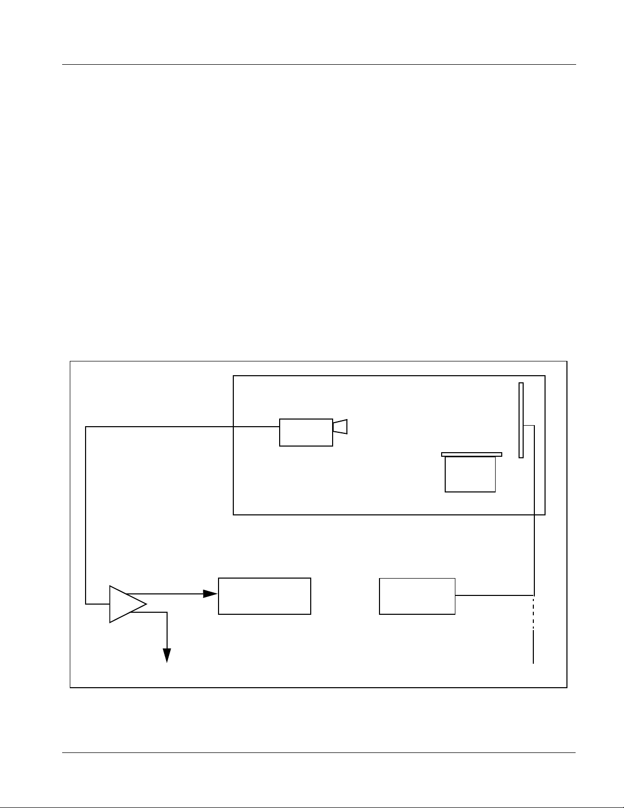
Operating Instructions Color and Video Correction Examples Using the 9064
Color and Video Correction Examples Using the 9064
Shown below are examples of us ing the 9064 to prov ide par ametri c color and
video correction.
On-Set Monitor Color Correction Example
A typical use for the 9064 Color Corrector function is to provide color
correction for a monitor when an anchor desk set includes a monitor, as
shown in Figure 3-6.
In the example setup shown in Figure 3-6, a monitor is located behind the
anchor desk. When the camera inclu des the mon itor in its shot, typically the
color balance of the monitor will appear to be incorrect due to the
characteristics of the camera responding differently to the spectral light
emissions from the monitor as compared to the natural light spectra emissions
that exist a cross the set overall. This monitor color balance problem is a
function of the camera(s), and can vary with different camera models.
Feed To Switcher
Anchor Desk Set with Monitor
WFM 7120 Waveform
Monitor
TG700 Siggen
From Monitor Video Feed
Figure 3-6 Example Uncompensated Setup
9064-OM (V4.1) 9064 PRODUCT MANUAL 3-37
Page 68

3 Color and Video Correction Examples Using the 9064
Ideally, this display would essentially result in a waveform showing identical
RGB components corresponding to the grayscale monochrome bar spectrum
being fed to the set monitor. However, as shown in Figure 3-7 with no
correction applied , the wa veform monit or shows i mbalance be tween the RGB
channels due to the reasons discussed above. Note the excessive offset, level,
and deviation from an ideal gamma curve for the blue channel.
Blue level in
excess of 100%
Non-ideal Gamma
curve
Figure 3-7 Uncorrected (Uncompensated) Monitor Waveform
Black (Offset) level
negative
FA-3.PNG
3-38 9064 PRODUCT MANUAL 9064-OM (V4.1)
Page 69

Operating Instructions Color and Video Correction Examples Using the 9064
Figure 3-8 shows the same setup using the 9064 Color Corrector function,
along with the appropriate signal source standard and a video waveform
monitor to assess and determine the color correction required. In the
calibration setup sh own in Figure 3- 8 the f eed to th e switc her is mon itore d by
a WFM 7120 Waveform Monitor, with the set monitor being fed a
monochrome linear limit ramp by a TG700 siggen.
Anchor Desk Set with Monitor
WFM 7120 Waveform
Monitor
To Switcher
Figure 3-8 Example Setup Using Control Panel Color Corrector Function
From Monitor Video Feed
TG700 Siggen
Using the 9064 Color Corrector function and setup shown in Figure 3-8, this
condition can be corrected through compensation using the 9064 Color
Corrector function as shown in Figure 3-9.
Note: As shown in Figure 3-9, a recommended approach to performing color cor-
rections is to first apply offset correction, then gain correction, and finally
gamma correction.
9064 Card
9064-OM (V4.1) 9064 PRODUCT MANUAL 3-39
Page 70
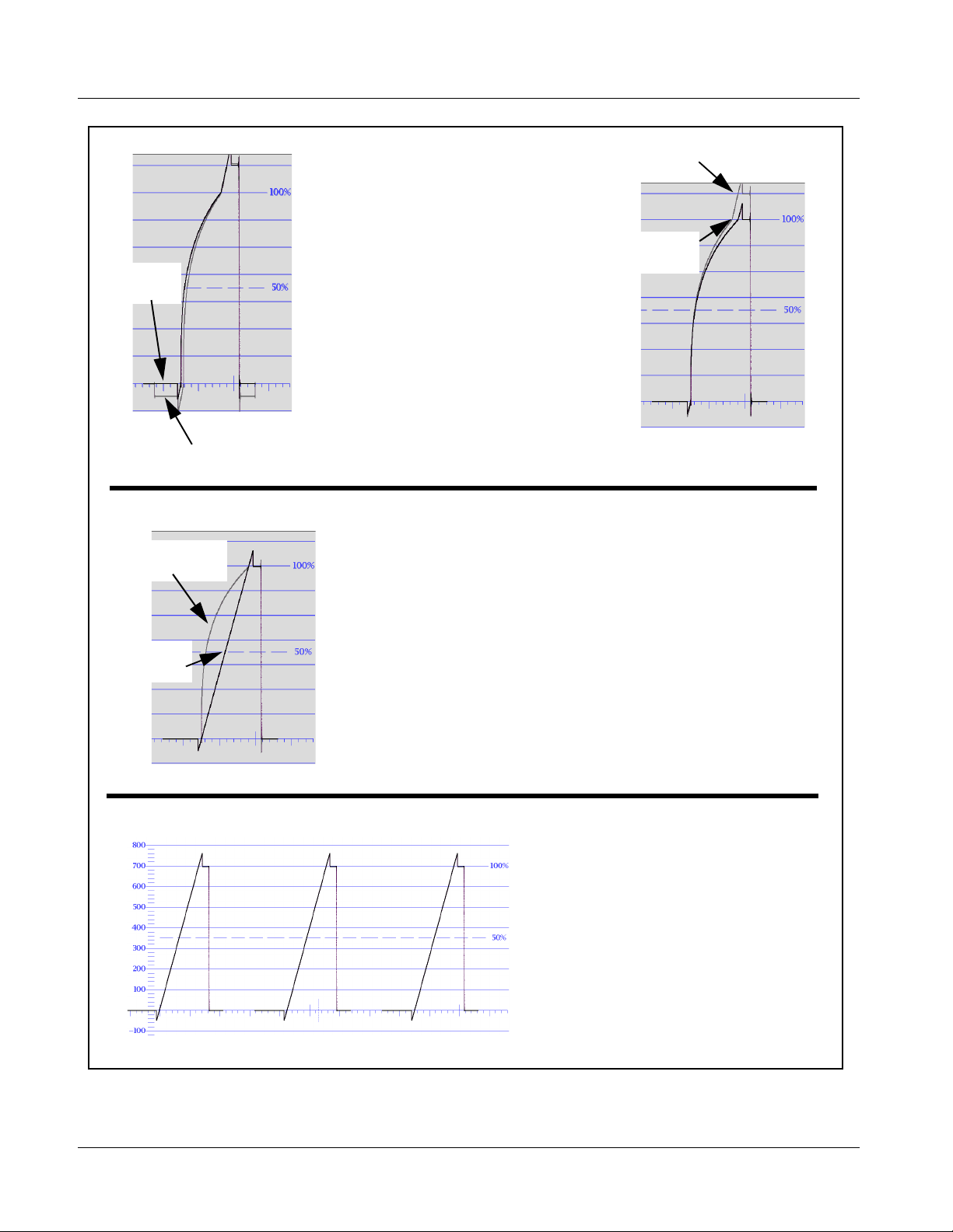
3 Color and Video Correction Examples Using the 9064
Uncompensated
Gain
(Left) Noting that the uncompensated black offset
for the blue channel is negative, a correspondingly
equivalent positive setting is applied using the blue
Corrected
Offset
channel Black offset control (in this example,
adjusting the Black offset from unity to 5.0 provides
compensation).
(Right) Noting that the uncompensated blue Gain
exceeds ideal 100% level, a correspondingly
smaller gain percentage setting is applied using the
blue channel Gain control until the gain is observed
as 100% (in this example, adjusting blue Gain from
unity to 87.5% provides compensation).
Corrected
Gain
FA-3A.PNG
Uncompensated black Offset
Uncompensated
Gamma
Corrected
Gamma
FA-3B.PNG
(Left) Noting that the uncompensated blue Gamma curve
indicates gamma factor is less than ideal 1.000, a
correspondingly greater numeric gamma factor is applied using
the blue channel Gamma control until the blue gamma function is
observed as linear (in this example, adjusting blue Gamma from
unity to 3.333 provides compensation).
FA-3C.PNG
(Left) Compensated Offset, Gain, and Gamma
are now symmetrical across all three color
channels, resulting in proper monitor
appearance in the OTA feed.
FA-3E.PNG
Figure 3-9 Applying Correction to Example Monitor Waveform Signal
3-40 9064 PRODUCT MANUAL 9064-OM (V4.1)
Page 71
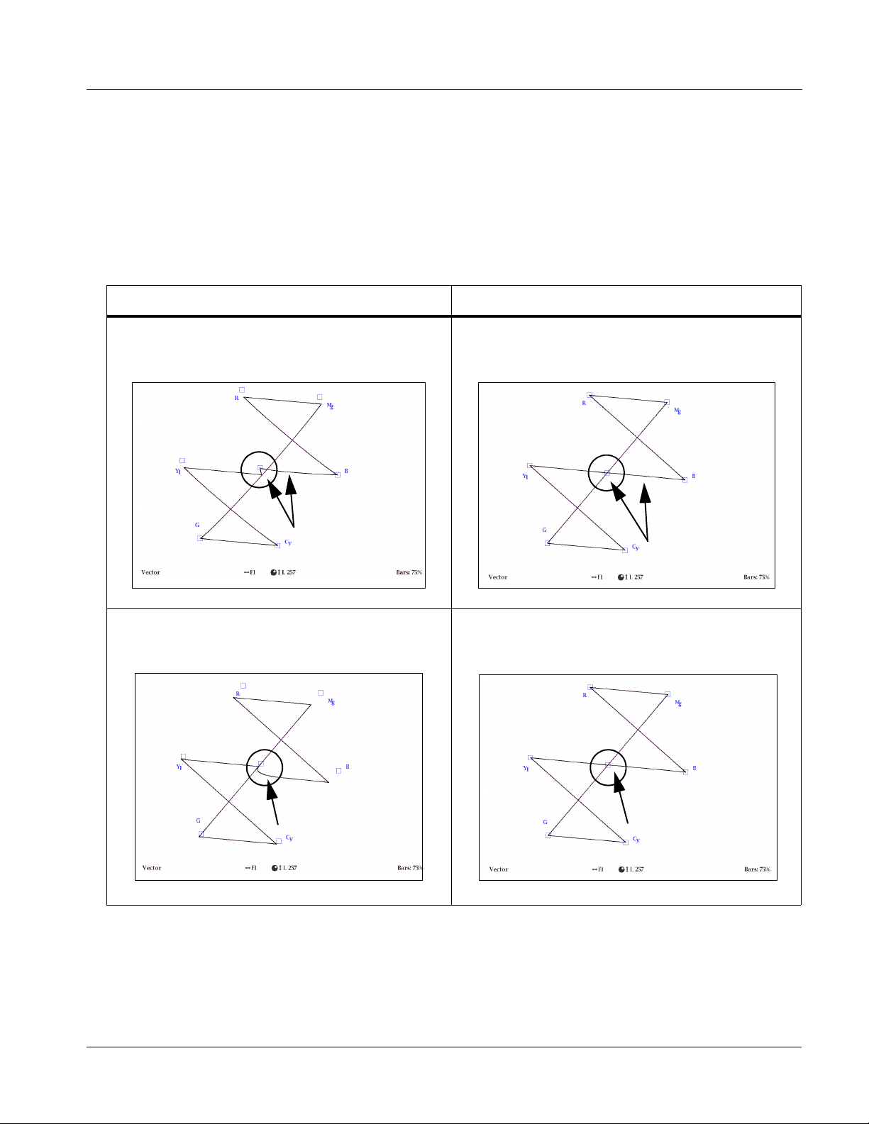
Operating Instructions Color and Video Correction Examples Using the 9064
Miscellaneous Color and Video Correction Examples
Table 3-3 provides examples showing and des cri bi ng va ri ous col o r and v ide o
condition corrections using the 9064.
Note: Signal generator and waveform monitor used in these examples are
Tektronix
Table 3-3 Color and Video Corrections Using the 9064
®
models TG700 and WFM 7120, respectively.
Condition Observed On Waveform Monitor Correction Using 9064
Excessive red channel Gamma (as shown below for
SMPTE color bars on vectorscope display)
VAR1.PNG
Using the red channel Gamma control to reduce Gamma
factor, vectorscope display now shows correction with no
knee or curvature at intersection of axes.
VAR2.PNG
Excessive green channel lift/offset (as shown below for
SMPTE color bars on vectorscope display)
VAR3.PNG
Using the green channel Black Adj control to reduce
green channel lift/offset, vectorscope display now shows
no droop along axis.
VAR2.PNG
9064-OM (V4.1) 9064 PRODUCT MANUAL 3-41
Page 72
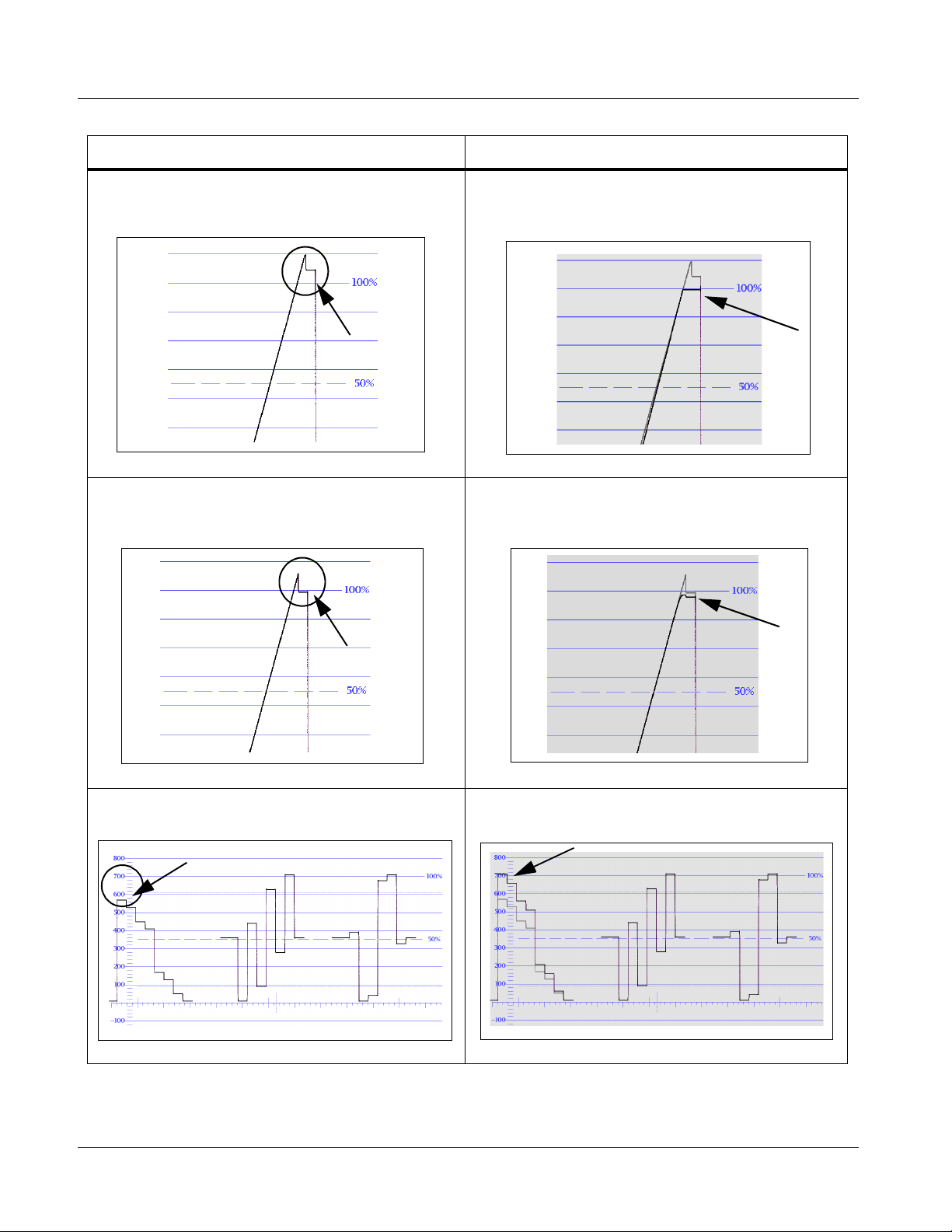
3 Color and Video Correction Examples Using the 9064
Table 3-3 Color and Video Corrections Using the 9064 — continued
Condition Observed On Waveform Monitor Correction Using 9064
White (luma) level exceeding 100% level (as shown
below for limit ramp monochrome bars on waveform
monitor display)
VAR4.PNG
White (luma) level exceeding 100% level (as shown
below for limit ramp monochrome bars on waveform
monitor display)
Using the White Hard Clip control, a lowered white hard
clipping threshold is applied to now limit the level to 100%.
VAR4A.PNG
Using the White Soft Clip control, a lowered white soft
clipping threshold is applied to now limit the level to 100%.
VAR5.PNG
Luma gain less than 100% level (as shown below for
100% color bars on YPbPr waveform monitor display)
VAR9.PNG
Using the Luma Gain control to increase luma gain, luma
gain is now restored to 100%.
VAR5A.PNG
VAR9A.PNG
3-42 9064 PRODUCT MANUAL 9064-OM (V4.1)
Page 73

Operating Instructions Color and Video Correction Examples Using the 9064
Table 3-3 Color and Video Corrections Using the 9064 — continued
Condition Observed On Waveform Monitor Correction Using 9064
Chroma gain exceeds 100% level (as shown below for
100% color bars on YPbPr waveform monitor display)
VAR10.PNG
Leading color phase condition (as shown below for
SMPTE color bars on vector display)
Using the Color Gain control to reduce chroma gain,
chroma gain is now restored to 100% level.
VAR10A.PNG
Using the Color Phase contro l to p rovide phas e lag, Colo r
Phase condition is now corrected.
Vectors are
advanced and do
not coincide with
0° points
VAR8.PNG
Vectors coincide
with 0° points
VAR8A.PNG
9064-OM (V4.1) 9064 PRODUCT MANUAL 3-43
Page 74

3 Troubleshooting
Troubleshooting
This section provides general troubleshooting information and specific
symptom/corrective action for the 9064 card and its remote control interface.
The 9064 card requires no periodic maintenance in its normal operation; if
any error indication (as described in this section) occurs, use this section to
correct the condition.
Error and Failure Indicator Overview
The 9064 card itself and its remote control systems all (to varying degrees)
provide error and failure indications. Depending on how the 9064 card is
being used (i.e, standalone or network controlled through DashBoard™ or a
Remote Control Panel), che ck all avai lable indi cations in the event of an error
or failure condition.
The various 9064 card and remote control error and failure indicators are
individually described below.
Note: The descriptions below provide general information for the various status and
error indicators. For specific failures, also use the appropriate subsection
listed below.
• Basic Troubleshooting Checks (p. 3-48)
• 9064 Processing Error Troubleshooting (p. 3-49)
• Troubleshooting Network/Remote Control Errors (p. 3-50)
3-44 9064 PRODUCT MANUAL 9064-OM (V4.1)
Page 75

Operating Instructions Troubleshooting
9064 Card Edge Status/Error Indicators and Display
Figure 3-10 shows and describes the 9064 card edge status indicators and
display. These indicators and the display show status and error conditions
relating to the card itself and remote (network) c ommunications (where
applicable). Because these indicators are part of the card itself and require no
external interface, the indicators are particularly useful in the event of
communications problems with external devices such as network remote
control devices.
4-Character Alphanumeric Display
RMT
REF
ERR
1080
720
625
525
9064
Status/Error
Indicators
Input Format
Indicators
Item Function
Alphanumeric
Display
RMT LED Blue LED flashes when 9064 is receiving control message from remote network control (e.g., DashBoard™
REF LED Blue LED illuminates indicating 9064 is receiving valid reference when set up for framesync operation.
ERR LED Red LED illuminates when 9064 unable to lock to framesync, or unable to lock to input standard.
Input Format
LEDs
Displays 4-digit alphanumeric code indicating status or errors as follows:
• E0XX: Video Errors
• E002: Video Acquiring Lock
• E2XX: Frame Sync Errors
• E200: Reference is Incompatible with Input Video
• E201: Reference Standard is Invalid/No Reference Present
• E202: Reference Standard is 720p2398 (a reference standard not supported by the framesync)
• E203: Reference Standard is 720p2997 (a reference standard not supported by the framesync)
®
or Cobalt
Four blue LEDs indicate the input signal raster format being received and locked onto by the 9064 (1080,
720, 625, 525). Continuous cycling of the LEDs indicates the 9064 has not locked onto a particular format (as
in the case of no signal input).
Remote Control Panel)
Figure 3-10 9064 Card Edge Status Indicators and Display
9064-OM (V4.1) 9064 PRODUCT MANUAL 3-45
Page 76
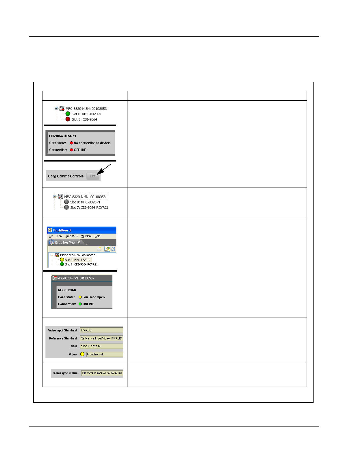
3 Troubleshooting
DashBoard™ Status/Error Indicators and Displays
Figure 3-11 shows and describes the DashBoard™ status indicators and
displays. These indicator icons and displays show status and error conditions
relating to the 9064 card itself and remote (network) communications.
Indicator Icon or Display Error Description
Red indicator icon in Card Access/Navigation Tree pane shows card with Error
condition (in this example, the Card Access/Navigation Tree pane shows a general
error issued by the 9064 card in slot 8).
Specific errors are displayed in the Card Info pane (in this example “No connection
to device” indicating 9064 card is not connecting to frame/LAN).
If the 9064 card is not connecting to the frame or LAN, all controls are grayed-out (as
shown in the example here).
Gray indicator icon in Card Access/Navigation Tree pane shows card(s) are not
being seen by DashBoard™ due to lack of connection to frame LAN (in this
example, both a 9064 card in slot 7 and the MFC-8320-N Network Controller Card
for its frame in slot 0 are not being seen).
Yellow indicator icon in Card Access/Navigation Tree pane shows card with Alert
condition (in this example, the Card Access/Navigation Tree pane shows a general
alert issued by the MFC-8320-N Network Controller Card).
Clicking the card slot position in the Card Access/Navigation Tree (in this example
Network Controller Card “Slot 0: MFC-8320-N”) opens the Card Info pane for the
selected card. In this example, a “Fan Door Open” specific error is displayed.
Yellow indicator icon in 9064 Card Info pane shows error alert, along with cause for
alert (in this example, the 9064 is receiving no video input, or a video input that is
invalid for the card and/or its current settings).
Where available, error messages within a function submenu pane show highly
specific information relating to detected errors (in this example, message shows an
invalid or missing Framesync Enable reference selection).
Figure 3-11 DashBoard™ Status Indicator Icons and Displays
3-46 9064 PRODUCT MANUAL 9064-OM (V4.1)
Page 77

Operating Instructions Troubleshooting
Access the Card Inf o pane fo r a speci fic car d by clic king the c ard slot positio n
in the Card Access/Navigation Tree pane (as shown in the example in Figure
3-12).
By clicking on “Slot 0: MFC-8320-N”
in this example, Card Info is
displayed for frame Network
Controller Card
By clicking on “Slot 7:
CDI-9064 RCVR21” in this
example, Card Info is shown
for 9064 card in slot 7
Status for selected card is
shown here (in this
example, connection OK
and “Fan Door Open”
alert)
Card general information
is displayed in lower
portion of Card Info pane
9064_TS_CARD_INFO_ACCESS.PNG
Status for selected
card is shown here
(in this example, all
indications are OK)
Where applicable,
additional status is
displayed (as shown in
this example)
9064_TS_CARD_INFO_ACCESS2A.PNG
Figure 3-12 Selecting Specific Cards for Card Info Status Display
9064-OM (V4.1) 9064 PRODUCT MANUAL 3-47
Page 78

3 Troubleshooting
Basic Troubleshooting Checks
Failures of a general nature (affecting many cards and/or functions
simultaneously), or gross inoperability errors are best addressed first by
performing basic checks before proceeding further. Table 3-4 provides basic
system checks that typically locate the source of most general problems. If
required and applicable, perform further troubleshooting in accordance with
the other troubleshooting tables in this section.
Table 3-4 Basic Troubleshooting Checks
Item Checks
Verify power presence and
characteristics
Check Cabl e connection
secureness and connecting
points
Card seating within slots Make certain all cards are properly seated within its frame slot. (It is best to assure
Check status indicators and
displays
Troubleshoot by substitution All cards within the frame can be hot-swapped, replacing a suspect card or module
• On both the frame Network Contro ller Card and t he 9064, in all cases when po wer is
being properly supplied there is always at least one indicator illuminated. Any card
showing no illuminated indicators should be cause for concern.
• Check the Power Consumed indications for both the +12 V and -7.5 V supply rails
for the 9064 card. This can be observed using the DashBoard™ Card Info pane, or
using the card edge controls and indicators as shown in Figure 3-4 on page 3-7.
• If either of the rail supplies show no power being consumed, either the frame
power supply, connections, or the 9064 card itself is defective.
• If either of the rail supplies show excessive power being consumed (see
Technical Specifications (p. 1-15) in Chapter 1, “Introduction”), the 9064 card
may be defective.
Make certain all ca ble connec tions are ful ly secure (inc luding coa xial cable att ach ment
to cable ferrules on BNC connectors). Also, make certain all connecting points are as
intended. Make certain the selected connecting points correlate to the intended card
inputs and/or outputs. Cabling mistakes are especially easy to make when working
with large I/O modules.
proper seating by ejecting the card and reseating it again.)
On both DashBoard™ and the 9064 card edge indicators, red indications signify an
error condition. If a st atus indic ator sig nifies an error, proceed to the following tables in
this section for further action.
with a known-good item.
3-48 9064 PRODUCT MANUAL 9064-OM (V4.1)
Page 79
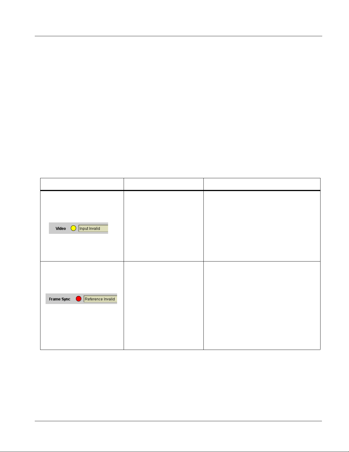
Operating Instructions Troubleshooting
9064 Processing Error Troubleshooting
Table 3-5 provides 9064 processing troubleshooting information. If the 9064
card exhib its any of the symptoms listed in Table 3-5, follow the
troubleshooting instructions provided.
In the majority of cases, most errors are caused b y simple errors where th e
9064 is not appropriately set for the type of signal being received by the card.
Note: The error indications shown below are typical for the corresponding error con-
ditions listed. Other error indications not specified here may also be displayed
on DashBoard™ and/or the 9064 card edge status indicators.
Note: Where errors are displayed on both the 9064 card and network remote con-
trols, the respective indicators and displays are individually described in this
section.
Table 3-5 Troubleshooting Processing Errors by Symptom
Symptom Error/Condition Corrective Action
• DashBoard™ shows Video
yellow icon and Input Invalid
message in 9064 Card Info
pane.
• Card edge Input Format LEDs
show continuous cycling.
• DashBoard™ shows Frame
Sync red icon and Reference
Invalid message in 9064 Card
Info pane.
• Card edge red ERR indicator
illuminated.
No video input present Make certain intended video source is
connected to appropriate 9064 ca rd video input.
Make certain BNC cable connections between
frame Rear I/O Module for the card and signal
source are OK.
Frame sync r eference not
properly selected or not being
received
• If external frame sync reference is not
intended to be used, make certain the
Framesync Enable selection list is set to Off
or Input Video as desired.
• If external frame sync reference is i ntended to
be used, make certain selected external
frame sync reference is active on frame sync
8320 frame bus. (External reference signals
Reference 1 and Reference 2 are distributed
to the 9064 and other cards via an 8320
frame bus.) Refer to Framesync function
submenu tab on page 3-27 for more
information.
9064-OM (V4.1) 9064 PRODUCT MANUAL 3-49
Page 80

3 Troubleshooting
Table 3-5 Troubleshooting Processing Errors by Symptom — continued
Symptom Error/Condition Corrective Action
DashBoard™ shows
Framesync St atu s error
message in 9064 Framesync
function submenu screen.
DashBoard™ shows Output
Status error message in 9064
Timecode function submenu
screen.
Ancillary data (closed cap tioning,
timecode, AFD, etc.) not
transferred through 9064.
Specifi ed Mi nim um Laten cy
Frames setting exceeds 9064
card buffer space for the
selected output video format
Timecode not available due to
lack of appropriate input
timecode da ta
• Control(s) not enabled • Make certain respective control is set to On or
• VANC line number conflict
between two or more
ancillary data items
• Reduce the Minimum Latency Frame s setti ng
as specified in the error message to correct
the error.
Note: Due to card mem ory limits, the maximum
available Minimum Latency Frames is
related to the output video format.
For example, with a 1080i59.94 output, the
maximum allowed setting is 5. For a 1080i
film (23.98) output, the maximum allowed
setting is 3. Conversely, greater maximum
settings are allowed for SD formats such as
525i59.94, where the practical maximum
limit is 13.
• Timecode output requires that source and
priority are appropri ately se lected. Al so, vide o
input must contain appropriate timecode data
and framesync reference.
Refer to Timecode functi on sub me nu tab on
page 3-31 for more information.
Enabled (as appropriate).
• Make certain each ancillary data item to be
passed is assigned a uni que line number (se e
Ancillary Data Line Number Locations and
Ranges on page 3-8).
Troubleshooting Network/Remote Control Errors
Refer to Cobalt® reference guide “COMPASS™ Remote Control User
Guide” (PN 9000RCS-RM) for network/remote control troubleshooting
information.
In Case of Problems
Should any problem arise with this product that was not solved by the
information in this section, please contact the Cobalt Digital Inc. Technical
Support Department.
If required, a Return Material Authorization number (RMA) will be issued to
you, as well as specific shipping instructions. If required, a temporary
replacement item will be made available at a nominal charge. Any shipping
costs incurred are the customer’s responsibility. All products shipped to you
from Cobalt Digital Inc. will be shipped collect.
The Cobalt Digital Inc. Technical Support Department will continue to
provide advice on any product manufactured by Cobalt Digital Inc., beyond
the warranty period without charge, for the life of the product.
See Contact Cobalt Digital Inc. (p. 1-19) in Chapter 1, “Introduction“ for
contact in formation.
3-50 9064 PRODUCT MANUAL 9064-OM (V4.1)
Page 81

Page 82

Cobalt Digital Inc.
2406 E. University Ave.
Urbana, IL 61802
Voice 217.344.1243 • Fax 217.344.1245
www.cobaltdigital.com
9064-OM (V4.1) Printed in USA
 Loading...