

Page 1
9061
Up/Down/Cross Converter
with Analog/SDI Input, Audio Embed/De-Embed,
Frame Sync, Timecode, and Closed Caption Support
Product Manual
Cobalt Digital Inc.
2406 E. University Ave.
Urbana, IL 61802
Voice 217.344.1243 • Fax 217.344.1245
www.cobaltdigital.com
9061-OM (V4.9)
Page 2

Copyright
©Copyright 2013, Cobalt Digital Inc. All Rights Reserved.
Duplication or distribution of this manual and any information contained within is strictly prohibited without the express written
permission of Coba lt Digital Inc. This manual and a ny information contained within, may not be re produced, distribute d, or
transmitted in any form, or by any means, for any purpose, without the express written permission of Cobalt Digital Inc.
Reproduction or reverse engineering of software used in this device is prohibited.
Disclaimer
The information in this document has been carefully examined and is believed to be entirely reliable. However, no responsibility
is assumed for inaccuracies. Furthermore, C obalt Digit al Inc. res erves the right to ma ke changes to any pro ducts herein to improve
readability, function, or design. Cobalt Digital Inc. does not assume any liability arising out of the application or use of any
product or circuit described herein.
Trademark Information
Cobalt® is a registered trademark of Cobalt Digital Inc.
COMPASS
openGear
Dolby
property of their respective owners.
Linear Acoust ic
licensed feature uses the AutoMAX-II™ upmix algorithm provided under licens e from
Linear Acoustic Inc. Linear Acoustic, the "LA" symbol, AutoMAX, and AutoMAX-II are trademarks of Linear Acoustic Inc.
All Rights Reserved.
®
and FUSION3G® are registered trademarks of Cobalt Digital Inc.
®
is a registered trademark of Ross Video Limited. DashBoard™ is a trademark of Ross Video Limited.
®
is a registered trademark of Dolby Laboratories, Inc. Other product names or trademarks appearing in this manual are the
®
, AEROMAX® and UPMAX® are registered trademarks of Linear Acoustic, Inc. 2.0-to-5.1 audio upmixer
®
Congratulations on choosing the Cobalt
Embed/De-Embed, Frame Sync, Timecode, and Closed Caption Support. The 9061 is part of a full line of
modular processing and conversion gear for broadcast TV environments. The Cobalt Digital Inc. line includes
video decoders and encoders, audio embedders and de-embedders, distribution amplifiers, format converters,
remote control syst ems and mu ch more. S hould you have qu estions pe rtaining to the inst allation o r operat ion of you r
9061, please contact us at the contact information on the front cover.
9061 Up/Down/Cross Converter with Analog/SDI Input, Audio
Manual No.: 9061-OM
Document Version: V4.9
Release Date: September 23, 2013
Applicable for
Firmware Version
3314
(or greater):
Description of
product/manual
changes:
- Update to correct image for Rear Module RM209061-E-DIN-HDBNC.
- Clarification of Framesync control descriptions.
- Update manual to include latest avai lab le ca rd
options.
9061-OM (V4.9)
Page 3

Table of Contents
Chapter 1 Introduction . . . . . . . . . . . . . . . . . . . . . . . . . . . . . . . . . . . . . . . . . . . 1-1
Overview ................................................................................................................ 1-1
9061 Card Software Versions and this Manual...................................................... 1-2
Cobalt Reference Guides........................................................................................ 1-2
Manual Conventions............................................................................................... 1-3
Warnings, Cautions, and Notes .................................................................. 1-3
Labeling Symbol Definitions...................................................................... 1-4
Safety Summary ..................................................................................................... 1-4
Warnings..................................................................................................... 1-4
Cautions...................................................................................................... 1-4
9061 Functional Description .................................................................................. 1-5
9061 Input/Output Formats ........................................................................ 1-5
Video Processor Description ...................................................................... 1-7
Audio Processor Description.................................................................... 1-13
AES Audio Input Advanced Features ...................................................... 1-19
User Control Interface .............................................................................. 1-20
9061 Rear I/O Modules ............................................................................ 1-22
Audio and Video Formats Supported by the 9061................................... 1-24
Technical Specifications....................................................................................... 1-25
Warranty and Service Information ....................................................................... 1-29
Cobalt Digital Inc. Limited Warranty....................................................... 1-29
Contact Cobalt Digital Inc.................................................................................... 1-30
Chapter 2 Installation and Setup . . . . . . . . . . . . . . . . . . . . . . . . . . . . . . . . . . . 2-1
Overview ................................................................................................................ 2-1
Setting I/O Switches for AES I/O (1-4) Ports ........................................................ 2-1
Installing the 9061 Into a Frame Slot ..................................................................... 2-2
Installing a Rear I/O Module.................................................................................. 2-4
9061 Rear I/O Modules .............................................................................. 2-6
Setting Up 9061 Network Remote Control .......................................................... 2-10
Chapter 3 Operating Instructions. . . . . . . . . . . . . . . . . . . . . . . . . . . . . . . . . . . 3-1
Overview ................................................................................................................ 3-1
Control and Display Descriptions........................................................................... 3-1
Function Submenu/Parameter Submenu Overview.................................... 3-2
DashBoard™ User Interface....................................................................... 3-3
Cobalt
9061-OM (V4.9) 9061 PRODUCT MANUAL i
®
Remote Control Panel User Interfaces.......................................... 3-4
Page 4

Accessing the 9061 Card via Remote Control........................................................ 3-5
Accessing the 9061 Card Using DashBoard™ ........................................... 3-5
Accessing the 9061 Card Using a Cobalt® Remote Control Panel ............. 3-6
Checking 9061 Card Information............................................................................ 3-7
Ancillary Data Line Number Locations and Ranges .............................................. 3-8
9061 Function Submenu List and Descriptions...................................................... 3-9
Video Signal Controls .............................................................................. 3-10
Audio Input Controls ................................................................................ 3-11
Video Proc ................................................................................................ 3-13
Scaler ........................................................................................................ 3-14
AFD .......................................................................................................... 3-19
Overlays ................................................................................................... 3-23
Framesync ................................................................................................ 3-27
Embedded Audio Group 1/2 .................................................................... 3-32
Embedded Audio Group 3/4 .................................................................... 3-36
AES Audio Out Pairs 1-4 ......................................................................... 3-38
AES Audio Out Pairs 5-8 ......................................................................... 3-42
Dolby Metadata ........................................................................................ 3-43
Closed Captioning .................................................................................... 3-44
Timecode .................................................................................................. 3-46
Audio Mixing ........................................................................................... 3-50
Tone Generator ......................................................................................... 3-55
Licensable Features .................................................................................. 3-55
Presets ...................................................................................................... 3-56
Advanced Setup ....................................................................................... 3-58
Audio Routing Example Using DashBoard™ .......................................... 3-59
Examples Using Audio LTC and RS-485 LTC Features.......................... 3-62
Troubleshooting .................................................................................................... 3-64
Error and Failure Indicator Overview....................................................... 3-64
Basic Troubleshooting Checks.................................................................. 3-68
9061 Processing Error Troubleshooting.................................................... 3-69
Troubleshooting Network/Remote Control Errors.................................... 3-72
In Case of Problems .................................................................................. 3-72
ii 9061 PRODUCT MANUAL 9061-OM (V4.9)
Page 5

Overview
Chapter 1
Chapter 1 Introduction
This manual provides installati on and o per at ing instr uct ions for the
9061 Up/Down/Cross Converter with Analog/SDI Input, Audio Embed/
De-Embed, Frame Sync, Timecode, and Closed Caption Support card (also
referred to herein as the 9061).
This manual consists of the following chapters:
• Chapte r 1, “Introduction” – Provides information a bout this manua l
and what is covered. Als o pr ovi des general information re gar di ng t he
9061.
• Chapter 2, “Installation and Setup” – Provides instructi ons for
installing the 9061 i n a fr ame, and option ally i nsta lling 9061 Rear I/O
Modules.
• Chapter 3, “Operating Instructions” – Provides overviews of
operating controls and instructions for using the 9061.
This chapter contains the following information:
• 9061 Card Software Ve rsions and this Manual (p. 1-2)
• Manual Conventions (p. 1-3)
• Safety Summary (p. 1-4)
• 9061 Functional Description (p. 1-5)
• Technical Sp ecifications (p. 1-25)
• Warranty and Service Information (p. 1-29)
• Contact Cobalt Dig ital Inc. (p. 1-30)
9061-OM (V4.9) 9061 PRODUCT MANUAL 1-1
Page 6

1 9061 Card Software Versions and this Manual
9061 Card Software Versions and this Manual
When applicable, Cobalt Digital Inc. provides for continual product
enhancements through software updates. As such, functions described in this
manual may pertain specifically to cards loaded with a particular software
build.
The Software Version of your card can be checked by viewing the Ca r d I n fo
menu in DashBoard™. See Checking 9061 Card Information (p. 3-7) in
Chapter 3, “Operating Instructio ns” for more infor mation. You can then check
our website for the lates t software version currently released for the card as
described below.
Check our website and proceed as follows if your card’s software does not
match the latest versi on:
Card Software earlier than
latest version
Card Software newer than
version in manual
Card is not loaded with the latest software. Not all
functions and/or specified performance described in
this manual may be available.
You can update your card with new Update
software by going to the Support>Firmware
Downloads link at www.cobaltdigital.com.
Download “Firmware Update Guide”, which
provides simple instructions for downloading the
latest firmware for your card onto your computer,
and then uploading it to your card through
DashBoard™.
Software updates are field-installed without any
need to remove the card from its frame.
A new manual is expediently released whenever a
card’s software is updated and specifications
and/or functionality have changed as compared
to an earlier version (a new manual is not
necessarily released if specifications and/or
functionality have not changed). A manual earlier
than a card’s software version may not completely
or accurately describe all functions available for
your card.
If your card shows features not described in this
manual, you can check for the latest manual (if
applicable) and download it by going to the
Support>Documents>Product Information and
Manuals link at www.cobaltdigital.com.
Cobalt Reference Guides
From the Cobalt® web home page, go to Support>Documents>Reference
Guides
updates, and other topics.
1-2 9061 PRODUCT MANUAL 9061-OM (V4.9)
for easy to use guide s covering network remot e control , card fir mware
Page 7

Introduction Manual Conventions
Manual Conventions
In this manual, display messages and connectors are shown using the exact
name shown on the 9061 itself. Examples are provided below.
• Card-edge display messages are shown like this:
Ch01
• Connector names are shown like this: AES IN 8
In this manual, the terms below are applicable as follows:
• 9061 refers to the 9061 Up/Down/Cross Converter with Analog/SDI
Input, Audio Embed/De-Embed, Frame Sync, Timecode, and Closed
Caption Support card.
Warnings, Cautions, and Notes
Certain items in this manual are highlighted by special messages. The
definitions are provided bel ow.
Warnings
Warning messages indicate a possible hazard which, if not avoided, could
result in pe rsonal injury or death.
• Frame refers to the HPF-9000, OG3-FR, 8321, or similar 20-slot
frame that houses Cobalt
• Device and/or Card refers to a COMPASS
• System and/or Video System refers to the mix of interconnected
®
or other cards.
®
card.
production and terminal equipment in which the 9061 and other
COMPASS
• Functions and/or features that are available only as an option are
®
cards operate.
denoted in th is manual like this:
Cautions
Caution messages indicate a problem or incorrect practice which, if not
avoided, could result in improper operation or damage to the product.
Notes
Notes provide supplemental information to the accompanying text. Notes
typically precede the text to which they apply.
9061-OM (V4.9) 9061 PRODUCT MANUAL 1-3
Page 8
1 Safety Summary
Labeling Symbol Definitions
Attention, consult accompanying documents.
Electronic device or assembly is susceptible to damage from an ESD
event. Han dle only using appropriate ESD prevention practices.
If ESD wrist strap is not available, handle card only by edges and avoid
contact with any connectors or components.
Symbol (WEEE 2002/96/EC)
For product disposal, ensure the following:
• Do not dispose of this product as unsorted municipal waste.
• Collect this product separately.
• Use collection and return systems available to you.
Safety Summary
Warnings
! WARNING !
Cautions
CAUTION
CAUTION
CAUTION
T o redu ce risk of electr ic shock do not remove line voltage service barrier cover on frame
equipment containing an AC power supply. NO USER SERVICEABLE PARTS INSIDE.
REFER SERVICING TO QUALIFIED SERVICE PERSONNEL.
This device is intended for environmentally controlled use only in appropriate video
terminal equipment operating environments.
This product is intended to be a component product of an openGear® frame. Refer to the
openGear® frame Owner's Manual for important safety instructions regarding the proper
installation and safe operation of the frame as well as its component products.
Heat and power distribution requirements within a frame may dictate specific slot
placement of cards. Cards with many heat-producing components should be arranged to
avoid areas of excess heat build-up, particularly in frames using only convection cooling.
The 9061 has a moderate power dissipation (24 W max.). As such, avoiding placing the
card adjacent to other cards with similar dissipation values if possible.
CAUTION
CAUTION
1-4 9061 PRODUCT MANUAL 9061-OM (V4.9)
If required, make certain Rear I/O Module(s) is installed before installing the 9061 into the
frame slot. Damage to card and/or Rear I/O Module can occur if module installation is
attempted with card already installed in slot.
If card resists fully engaging in r ear I/O module mating connector, check for alignment a nd
proper insertion in slot tracks. Damage to card and/or rear I/O module may occur if
improper card insertion is attempted.
Page 9

Introduction 9061 Functional Description
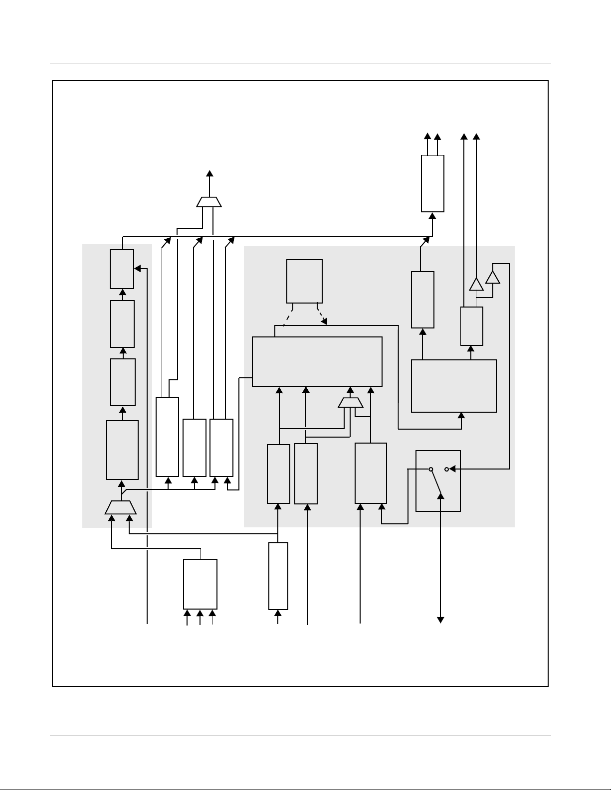
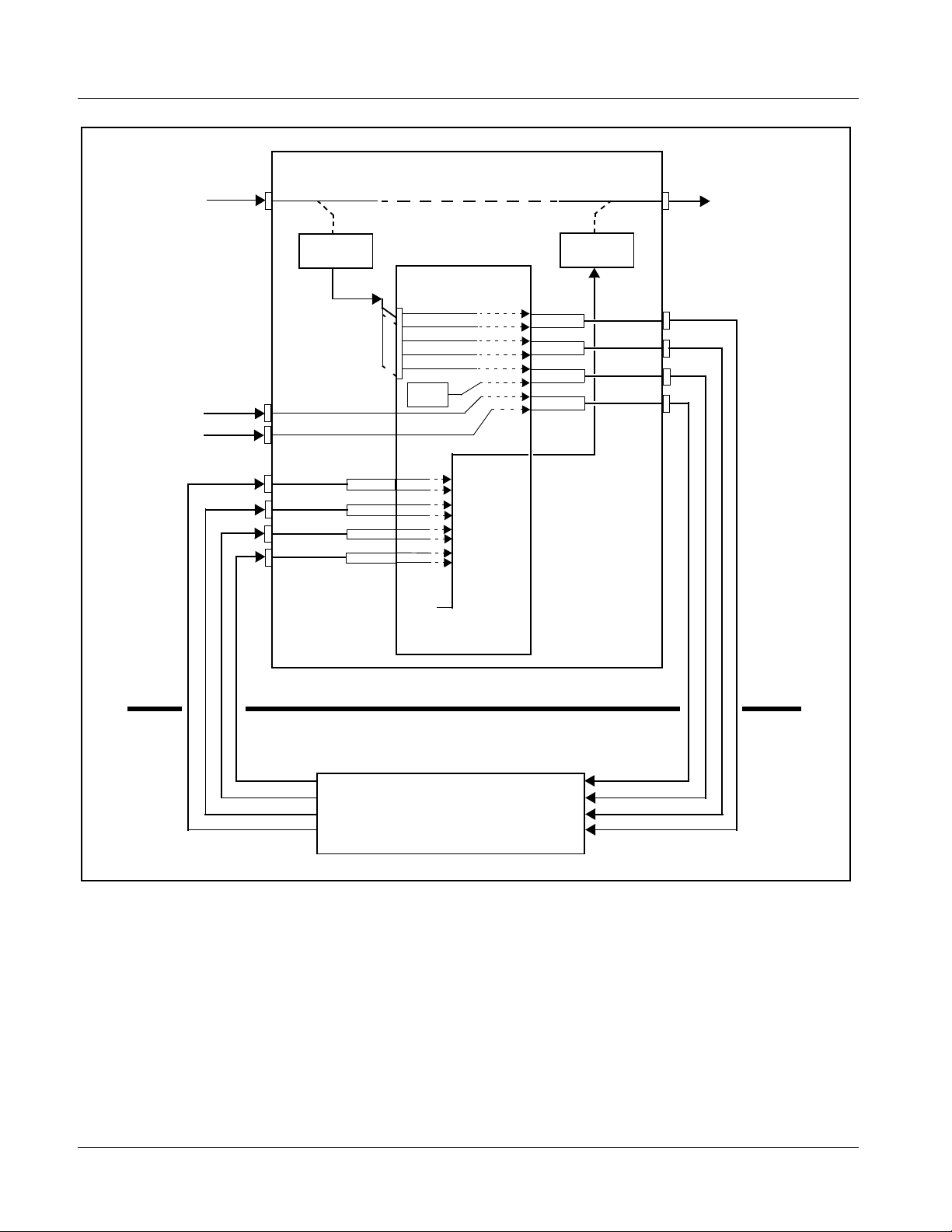
9061 Functional Description
Figure 1-1 shows a functional block diagram of the 9061. The 9061 format
converter also includes a full 16-c hannel audio embedder/de-embedde r, a
12-bit analog-to-digital video converter, an 8-channel, 24-bit balanced
analog-to-digital audio converter, and a full video frame synchronizer. The
9061 also handles AFD code detection and processing, timecode support,
closed captioning support, and transfer of Dolby
As such, the 9061 is highly suited as a universal input processing card with
comprehensive audio and video support. The video source can be either an
HD/SD-SDI input or an HD/SD analog video input. The video can be up,
down, or cross-converted to a different format, and aspect ratio can be
corrected to provide proper output aspect.
®
metadata.
Note: Some of the functions described below are available only when using the
9061 Input/Output Formats
DashBoard™, or Cobalt
user interfaces. Refer to User Control Interface (p. 1-20) for user interface
descriptions.
®
OGCP-9000 or OGCP-9000/CC Control Panels
The 9061 provides the following inputs and outputs:
• Inputs:
• HD/SD SDI IN – dual-rate HD/SD-SDI input
• Y/Cmpst IN, Pr/C IN, Pb IN – analog composite/component video
inputs
• AES I/O (1-4) – user-switchable as AES inputs or AES outputs
• AES IN (5-8) – dedicated AES inputs
• AN-AUD IN (1-8) – balanced analog audio inputs
• Outputs:
• SDI OUT – two dual-rate HD/SD-SDI buffered video outputs
• AES OUT (1-8) – dedicated AES outputs
• AES I/O (1-4) – user-switchable as AES inputs or AES outputs
• RS-485 – RS485 Dolby
®
metadata output (with option +LTC, also
provides RS-485 LTC I/O)
Note: The input/output complement listed above represents the maximum capability
of the 9061. The practical input/output complement is determined by the particular Rear I/O Module used with the 9061. Refer to 9061 Rear I/O Modules
(p. 1-22) for more information.
9061-OM (V4.9) 9061 PRODUCT MANUAL 1-5
Page 10
1 9061 Functional Description
1. Signal connections shown depicts
Notes:
SDI OUT
RS-485
I/O
(NOTE 3)
full input/output capability.
Rear I/O Modules,” 1-22 for more
Practical input/output signal
availability is determined by Rear
I/O Module used. Refer to “9061
information.
licensable feature.
adds LTC I/O via audio I/O and
2. Optional 2.0-to-5.1 upmixer (+UM)
Sync
Frame
RS-485.
3. Optional +LTC licensable feature
(NOTE 2)
Upmixer
2.0-to-5.1
Active: Overwrites
6 selected channels
with new 5.1 mix.
See text.
Bypass: Bypasses
2.0-to-5.1 upmixer;
all original channels
pass unaffected.
Serializer/
Audio
Embed
AFD
Processing
Dolby Meta Out
Gain
Audio
Control
Routing/
Cable Drivers
AES OUT
(5-8)
(1-4)
AES
Encode
Video
Processing
RS-485 LTC I/O
VBI Timecode
Audio LTC (NOTE 3)
Down/
Mono
Mixer
Tracking
Delay and
Framesync
User Offset
TC
CC
Re-insert
Processing
Pr/C IN
Processing
Audio
Analog
Audio A/D
De-Embed
Audio Processor
AES Decode
and SRC
S11–S14
[AES IN (1-4)]
A/D
EQ/Deserialize
Pb IN
HD/SD SDI IN
IN (1-8)
AN-AUD
AES IN (5-8)
AES I/O (1-4)
Up/Down/
Cross-Format
Conversion
Metadata Extract/
Video Processor
Video
IN (1,2)
EXT REF
(from frame)
Y/Cmpst IN
[AES OUT (1-4)]
9061V4.4BD
Figure 1-1 9061 Functional Block Diagram
1-6 9061 PRODUCT MANUAL 9061-OM (V4.9)
Page 11

Introduction 9061 Functional Description
Video Processor Description
The 9061 features a scaler that provide s up, down, and cross- conversion usi ng
de-interlacing and motion adaptation for high quality up-conversions. The
scaler also provides user-adjustable aspect ratio control and zoom control.
Separate controls are provided for SD and HD inputs that allow the card to
flexibly and independently handle mixed input formats.
The 9061 video subsystem also provides the functions described below.
Video Processor
The 9061 provides full color processing control (luma gain and lift, chroma
saturation, and color phase) of the output video.
Frame Sync Function
This function p rovide s for fra me s ync co ntrol usin g e ither one of t wo ext ern al
EXT REF IN (1,2) reference sign als di stri buted wit h the ca rd fra me, or the inpu t
video as a frame sync reference.
This function also allows horizontal and/or vertical offset to be added
between the output video and the frame sync reference.
A video/audio delay offset function allows adding or reducing audio delay
from the matching video delay. This function is useful for correcting lip sync
problems when video and audio paths in the chain experience differing
overall delays. A Reset Framesync function resets the frame sync following
any horizontal or vertical offset changes, clearing any buffered audio and
video and re-establ ishing t he frame s ync. The 906 1 re-est ablishes vi deo/audi o
sync following framesy nc changes by appl ying an of fset in small, progre ssive
amounts to provide a seamless, glitch-free retiming. A user-selectable hard
resync function allows setting a threshold at which hard resync is applied if
audio-video offset exceeds a selectable threshold. Hard resync provides
fastest snyc-up suitable for off-air manipulation. Conversely, a threshold
setting that avoids hard resync allows glitch-free on-air manipulation.
In the event of input video loss of signal, this function provides for disabling
the video, going to a des ired color raster, or freezing to the last intact frame
(for SDI, last frame having valid SAV and EAV codes; for analog, last frame
free of timing errors).
9061-OM (V4.9) 9061 PRODUCT MANUAL 1-7
Page 12

1 9061 Functional Description
Scaler Function
The scaler function provides up, down, and cross-conversions between
multiple standard SD and HD video formats, multiple frame rates, film frame
rates, and cross-c onversion bet ween interla ced and progre ssive formats . T a ble
1-1 lists the 9061 conversion choices available for various input formats and
frame rates.
Table 1-1 Scaler Function Conversions
Input
Format
525i 59.94 525i 59.94 720p 59.94 720p 29.97 720p 23.98
SD
(NTSC/
PAL)
720p
720p
half-rate
720p
(film rates)
(4)
1080i 1080p
1080p
(film rates)
1080i 59.94 1080p 29.97 1080p 23.98
1080PsF 23.98
(4)
1080PsF
(film rates)
625i 50 625i 50 720p 50 720p 25 X 1080i 50 1080p 25 X X
720p 60 X 720p 60 720p 30 720p 24
(4)
720p 59.94 525i 59.94 720p 59.94 720p 29.97 720p 23.98
1080i 60 1080p 30 1080p 24
1080i 59.94 1080p 29.97 1080p 23.98
(4)
(4)
(4)
1080PsF 24
(4)
1080PsF 23.98
720p 50 625i 50 720p 50 720p 25 X 1080i 50 1080p 25 X X
720p 30 X 720p 60 720p 30 720p 24
(5)
720p 29.97 525i 59.94 720p 59.94 720p 29.97 720p 23.98
1080i 60 1080p 30 1080p 24
1080i 59.94 1080p 29.97 1080p 23.98
(5)
(5)
(5)
1080PsF 24
(5)
1080PsF 23.98
720p 25 625i 50 720p 50 720p 25 X 1080i 50 1080p 25 X X
720p 24 X 720p 60 720p 30 720p 24 1080i 60 1080p 30 1080p 24 1080PsF 24
720p 23.98 525i 59.94 720p 59.94 720p 29.97 720p 23.98 1080i 59.94 1080p 29.97 1080p 23.98 1080PsF 23.98
1080i 60 X 720p 60 720p 30 720p 24
(4)
1080i 59.94 525i 59.94 720p 59.94 720p 29.97 720p 23.98
1080i 60 1080p 30 1080p 24
1080i 59.94 1080p 29.97 1080p 23.98
(4)
(4)
(4)
1080PsF 24
(4)
1080PsF 23.98
1080i 50 625i 50 720p 50 720p 25 X 1080i 50 1080p 25 X X
1080p 30 X 720p 60 720p 30 720p 24
(5)
1080p 29.97 525i 59.94 720p 59.94 720p 29.97 720p 23.98
1080i 60 1080p 30 1080p 24
1080i 59.94 1080p 29.97 1080p 23.98
(5)
(5)
(5)
1080PsF 24
(5)
1080PsF 23.98
1080p 25 625i 50 720p 50 720p 25 X 1080i 50 1080p 25 X X
1080p 24 X 720p 60 720p 30 720p 24 1080i 60 1080p 30 1080p 24 1080PsF 24
1080p 23.98 525i 59.94 720p 59.94 720p 29.97 720p 23.98 1080i 59.94 1080p 29.97 1080p 23.98 1080PsF 23.98
1080PsF 24 X 720p 60 720p 30 720p 24 1080i 60 1080p 30 1080p 24 1080PsF 24
1080PsF 23.98 525i 59.94 720p 59.94 720p 29.97 720p 23.98 1080i 59.94 1080p 29.97 1080p 23.98 1080PsF 23.98
Notes: 1. The drop-down list choice of “Same as Input” is used when no conversion is desired. For clarity, it is not redundantly listed here.
2. “X” denotes conversions not available or invalid conversions.
3. Interlaced formats rates listed are field rates. Progressive format rates listed are frame rates.
4. If the original material does not have a proper 3-2 cadence suitable for conversion to film rates, the conversion reverts t o standard
de-interlacing. While this video can be converted to film rates, the resulting image motion will lack smoothness. Therefore, make
certain interlaced video is appropriately constructed for 3-2 reverse pulldown when converting video to film rates. See 3-2
Pulldown Conversion and Considerations (p. 1-12).
5. Formats using a 30/29.97 Hz progressive frame rate can be converted to a 24/23.98 Hz progressive frame rate, however some
image motion irregularity will appear in the converted output.
6. “NTSC” and “PAL” in this manual respectively denote 525i5994 and 625i50 SD analog formats, and informally 486i5994 and
575i50 SD-SDI video formats.
(4)
(4)
(5)
(4)
(5)
1-8 9061 PRODUCT MANUAL 9061-OM (V4.9)
Page 13

Introduction 9061 Functional Description
When output video is set to 720p for either SD or HD video, the 720p output
can be converted to 7 20p half-r ate for mats as lis ted in Table 1-1. When output
video is set to 1080 film (1080p23.98) for either SD or HD inputs, the 9061
can convert the output to 1080P sF23. 98 (seg mente d frame progre ssive) . Both
of these functions c an be i ndepend ently appli ed to e ither SD and/o r HD vide o
inputs.
The scaler function also provides aspect ratio conversion that provides a
choice from several standard aspect ratios. Additionally, user defined and
“Follow AFD Settings” conversion can be applied. User defined settings
allow custom user-defined H and V aspect ratio control. “Follow AFD
Settings” sets the output aspect ratio to track with AFD (Active Format
Description) settings embedded in the received video signal.
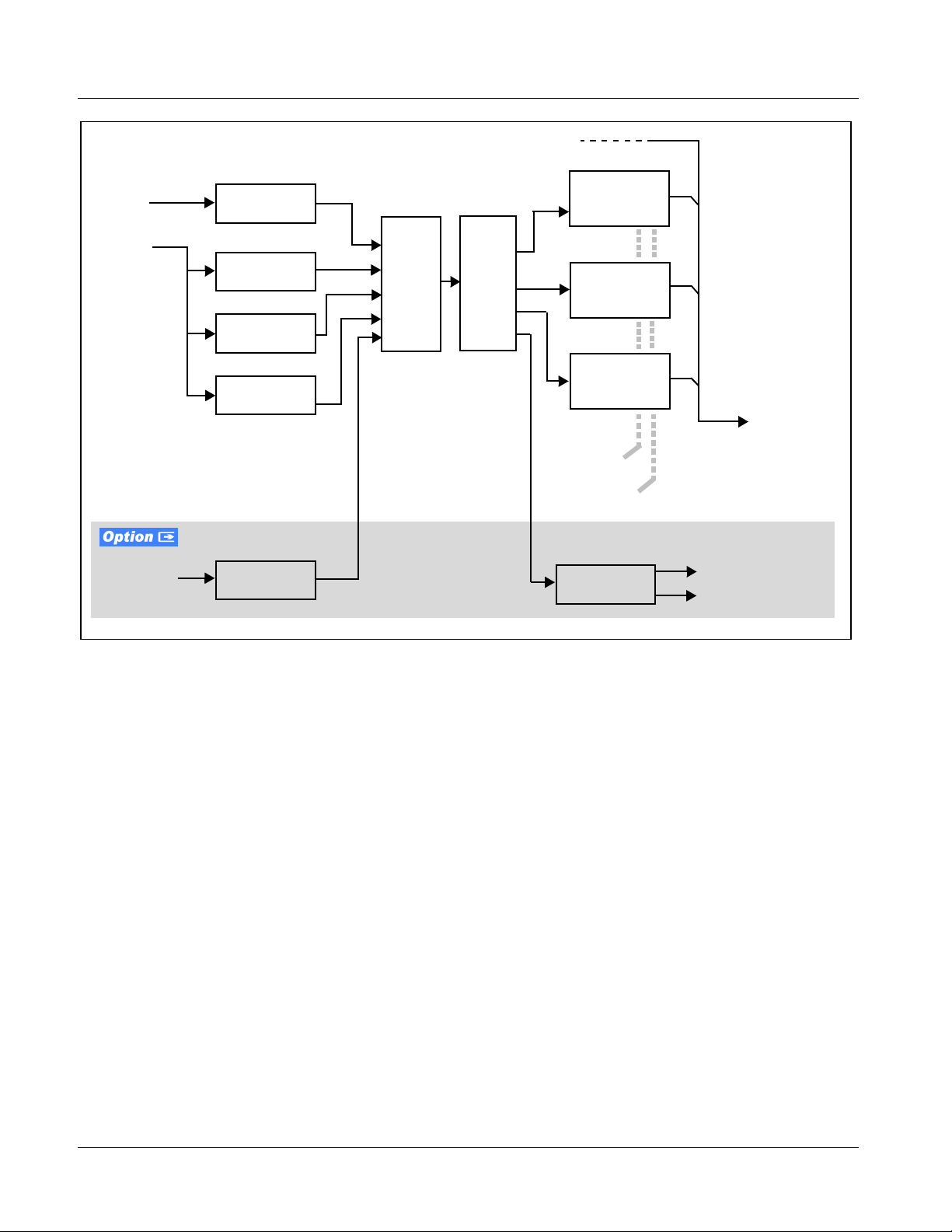
Timecode Processor
(See Figure 1-2.) This fun ct ion provi de s for ext rac ti on of time code data fro m
the input video, and in turn re-insertion of timecode data into the output SDI.
In this manner, timecode data can be preserved, even after fo rmat conv ersi on.
The function can monitor analog and SDI video streams for supported
timecode formats and then select and prioritize among analog VITC, SDI
VITC, SDI ATC_VITC, and SDI ATC_LTC. If the preferred format is
detected, the preferred format is used by the ca rd; if the pre ferred format is
not detected, the card uses other formats (where available) as desired.
The function also provi des con ver sion be tween va rious timecod e fo rmats a nd
provides independent insertion and line number controls for each SDI
timecode output format.
Option
between VBI formats over SDI and audio LTC, as well as RS-485 LTC.
Audio LTC can be received or sent over a selected balanced analog audio
input, or as digital audio over a selected embedded or AES input.
+LTC allows bidirectional transfer and conversion
9061-OM (V4.9) 9061 PRODUCT MANUAL 1-9
Page 14
1 9061 Functional Description
HD/SD–SDI
(From Video Proc)
Analog
Video
Input
SDI
Video
Input
Audio/
RS-485 LTC
Analog VITC
Detect/Extract
SDI VITC
Detect/Extract
SDI ATC_VITC
Detect/Extract
SDI ATC_LTC
Detect/Extract
Audio LTC
Select/Extract
Priority/
Select
Buffer/
Format
SDI VITC
Timecode
Proc/Embed
ATC_VITC
Timecode
Proc/Embed
ATC_LTC
Timecode
Proc/Embed
Insert
Control
Line
Number
Control
Audio/RS-485
LTC Generate
HD/SD–SDI
Video Output
Audio LTC Out
RS-485 LTC Out
Figure 1-2 Timecode Processor
Closed Captioning Processor
This function provides support for closed captioning setup. When enabled,
the function selects from current input video, analog SD, or SDI as the source
of closed captioning data. The function also allows the selection of the
ancillary data li ne numbe r where t he ancil lary cl osed capt ion data is outp utted
when the output is HD. When receiving HD-SDI, both CEA 608 and CEA
708 are supported, with CEA 608 and CEA 708 (containing CEA 608
packets) converted to li ne 21 cl osed c aptio ning on o utp uts down- conver ted t o
SD (on up-convert of SD, only CEA 608 closed captioning is generated).
Dolby® Metadata Extractor/Re-inserter
This function extract s and preserv es Dolby® metadata from the input SDI, and
in turn allows the metadata to be re-inserted in the output SDI. This allows
scaling and/or format conversions without losing Dolby
9061 does not offer Dolby
and/or Dolby
®
Digital™ encoded signals and metadata intact.) The extracted
®
decoding or encoding, but will pass Dolby
metadata is buffered and then output on a user-selectable line number on the
SDI output, and on the
RS-485 I/O connector (on cards equipped with
appropriate Rear I/O Module).
®
metadata. (The
®
E
1-10 9061 PRODUCT MANUAL 9061-OM (V4.9)
Page 15

Introduction 9061 Functional Description
AFD Processor
This function provides aspect ratio controls and assignment of AFD codes to
the SDI output video.
Using this function, aspect ratios in accordance with the standard 4-bit AFD
codes can be applied to the output video. Additionally, custom aspect ratios
can be independently defined for any of the AFD codes.
Separate, independent AFD cont rols are provided for bot h 16:9 coded and 4:3
coded frames.
This function also provides AFD-controlled ARC by checking for any
existing AFD code within the received video input. If a code is present, the
code is displayed. With the Scaler function
Follow AFD Settings, the H and V settings corresponding to the received code
are applied to the video by the 9061. The default, standard aspect ratio
described by the AFD code can be applied, or custom horizontal/vertical
scaling can be applied for a given code.
The function also allows the selection/changing of the AFD code and
ancillary data line number for the outputted AFD code.
Aspect Ratio Conversion set to
9061-OM (V4.9) 9061 PRODUCT MANUAL 1-11
Page 16
1 9061 Functional Description
3-2 Pulldown Conversion and Considerations
Figure 1-3 depicts the 3-2 pulldown process used for conversions between
progressive film video formats and interlaced video formats. (Although the
term “3-2” is used here per convention, it is more accurately described as 2-3
per the diagram here and SMPTE definitions which stipulate that first film
frame
A be represented exclusively by 2 fields from the same frame). As
shown in Figure 1-3, the term 2-3 is derived from the pattern, or cadence, in
which four consecutive fi lm video frames are convert ed i nto five consecutive
interlaced video frames (i.e., 10 interlaced video fields). Odd and even interlaced fields are denoted in Figure 1-3 by “
“
A
”). Note the considerations described in Figure 1-3 for converting to film
E
rates.
3-2 Pulldown
(From 1080p 24 To 1080i 60)
“
2” portions consist of two consecutive interlaced fields sourced from the same film
frame. The first film frame and first video frame are unique as a set in that their
contents are mutually and exclusively related to each other.
” and “E” (for example, “AO” and
O
1080p 24
1080i 60
1080i 60
1080p 24
“3” portions consist of three consecutive interlaced fields sourced from the
same film frame distributed across three consecutive interlaced fields.
A B C D
1
AOA
3
2
BOB
E
E
3
BOC
X
2
E
A B C
AOA
E
[1O1E]
Using reverse pulldown, each film video frame is constructed from 2 interlaced fields with odd and even fields selected
as shown. The conversion pattern shown reverses the pulldown, thereby restoring the original signal.
Note: If the original interlaced material does not have the cadence described here, the conversion reverts to standard
de-interlacing. While this video can be converted to film rates, the resulting image motion will lack smoothness.
Therefore, make certain interlaced video is appropriately constructed for reverse pulldown when converting video to film
rates. Similarly, formats using a 30/29.97 Hz progressive frame rate can be converted to a 24/23.98 Hz progressive
frame rate, however some image motion irregularity will appear in the converted output.
BOB
[2O2E]
E
COC
[4O3E]
32
45
COD
DOD
E
X
E
D
DOD
E
E
[5O5E]
A B C D
2
1
AOA
2
BOB
E
E
3
BOC
X
E
A B C
AOA
[1O1E]
BOB
E
E
[2O2E]
COC
[4O3E]
32 3
45
COD
E
X
E
DOD
[5O5E]
DOD
E
D
E
3-2 Reverse Pulldown
From 1080i 60 To 1080p 24
Figure 1-3 3-2 Pulldown and Reverse Pulldown
1-12 9061 PRODUCT MANUAL 9061-OM (V4.9)
Page 17

Introduction 9061 Functional Description
Audio Processor Description
The audio processor operates as an internal audio router. The router function
chooses from the following inputs:
• 16 channels of embedded audio from the SDI video
• 16 channels (8 pairs) of discrete AES input
• 8 channels of balanced analog audio input
• Four independent internal tone generators (described below)
• Digital silence (mute) setting
• Internal Down Mix and Mono Mixer outputs (described below)
The router function provides the following audio outputs:
• 16 channels of embedded audio on the SDI output
• 16 channels of discrete AES output on eight AES pairs
The router acts as a full audio cross point. Each of th e 32 out put cha nnels (16
embedded, 16 discrete AES) can receive signal from any one of the 40 (16
embedded AES, 16 discr et e AES, 8 analog) input channels , f our i nt er nal t one
generators, or several mixer outputs. Unused output channels can be mapped
to a “Silence” source. Each output also provides gain adjustment and
selectable polarity inversion.
Output audio rates are always 48 kHz locked to output video, but discrete
AES inputs can pass through the sample rate converters to align these inputs
with the output timing. (AES must be nominally 48 kHz input; 32, 44.1, 96,
and 192 kHz inputs are not compatible with the 9061.) The sample rate
converters are disabled by default. Output AES is always precisely
synchronized with the output video. The balanced analog audio input is
sampled at 48 kHz with a +24 dBu clipping level (+24 dBu => 0 dBFS).
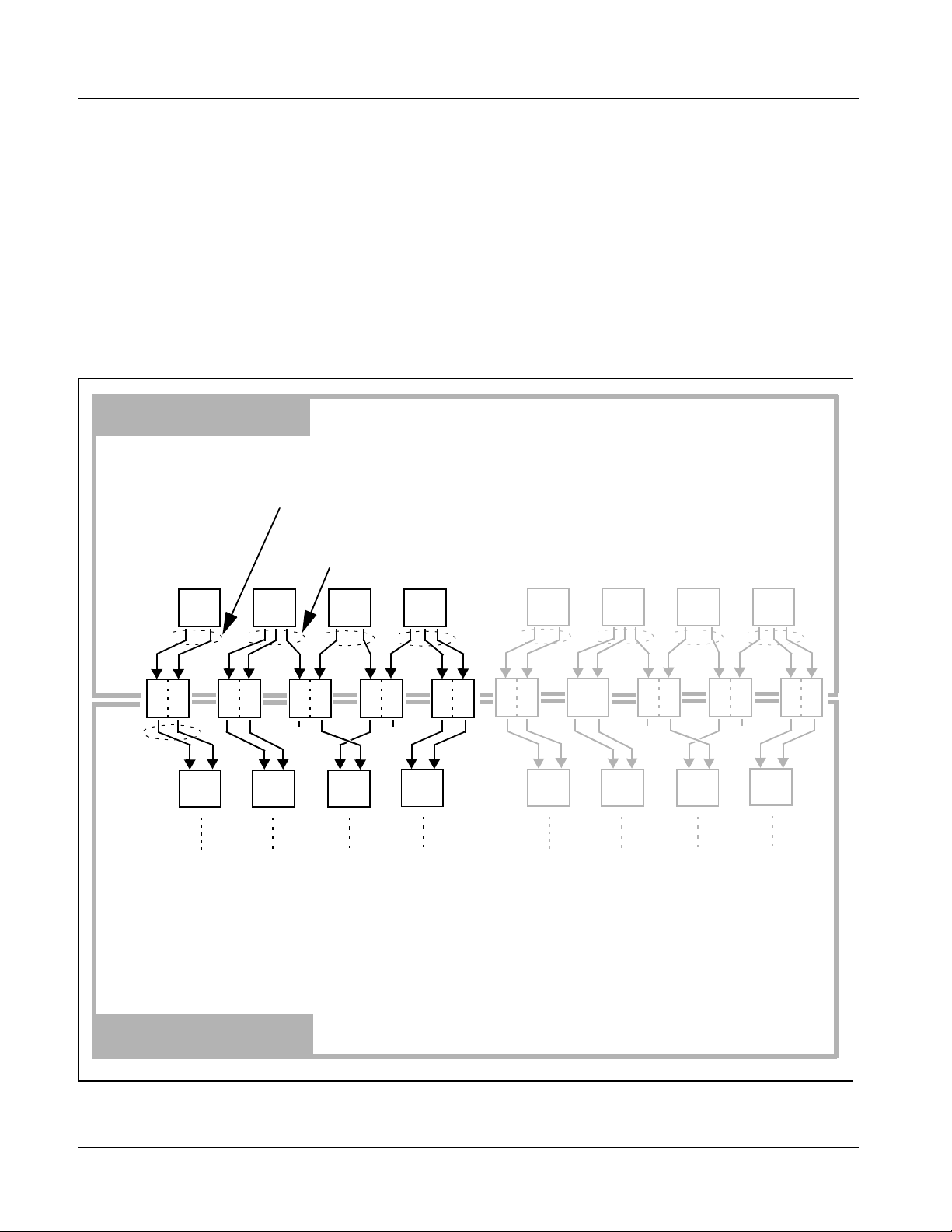
As set with the default settings, t he routing be tween embedded aud io channels
Embed Ch 1 thru Embed Ch 16 and discrete AES a udi o ch anne ls AES Ch1 thru
AES Ch 16 is as shown in Figure 1-4. In this mode, the routing is basic 1-to-1
embedding/de-embedding for the 16 embedded and AES discrete audio
channels. Other sources and/or destinations (described below) for each
channel are selected using the card edge controls or a remote control system.
Note: As shown in Figure 1-1, the 9061 is equipped with eight discrete AES input
pair ports and eight discrete AES output pair ports. On Rear I/O Modules having limited AES I/O capabilities, switches S11 thru S14 allow available rear
module BNC connectors to be allotted between AES inputs and outputs as
desired. Buffered copies of
and as respective outputs fed through S11 – S14 on the 9061 card.
AES OUT (1-4) are available as dedicated outputs
9061-OM (V4.9) 9061 PRODUCT MANUAL 1-13
Page 18
1 9061 Functional Description
AES Ch 1
AES Ch 8
AES Ch 9
AES Ch 16
Embedded Audio
Group 1/2
Embed Ch 1
•
•
•
Embedded Audio
•
•
•
•
•
•
Embed Ch 8
Group 3/4
Embed Ch 9
•
•
•
Embed Ch 16
AES Audio Out
Pairs 1-4
AES Ch 1
•
•
•
AES Ch 8
AES Audio Out
Pairs 5-8
AES Ch 9
•
•
•
AES Ch 16
Figure 1-4 Default Embed/De-Embed Audio Routing
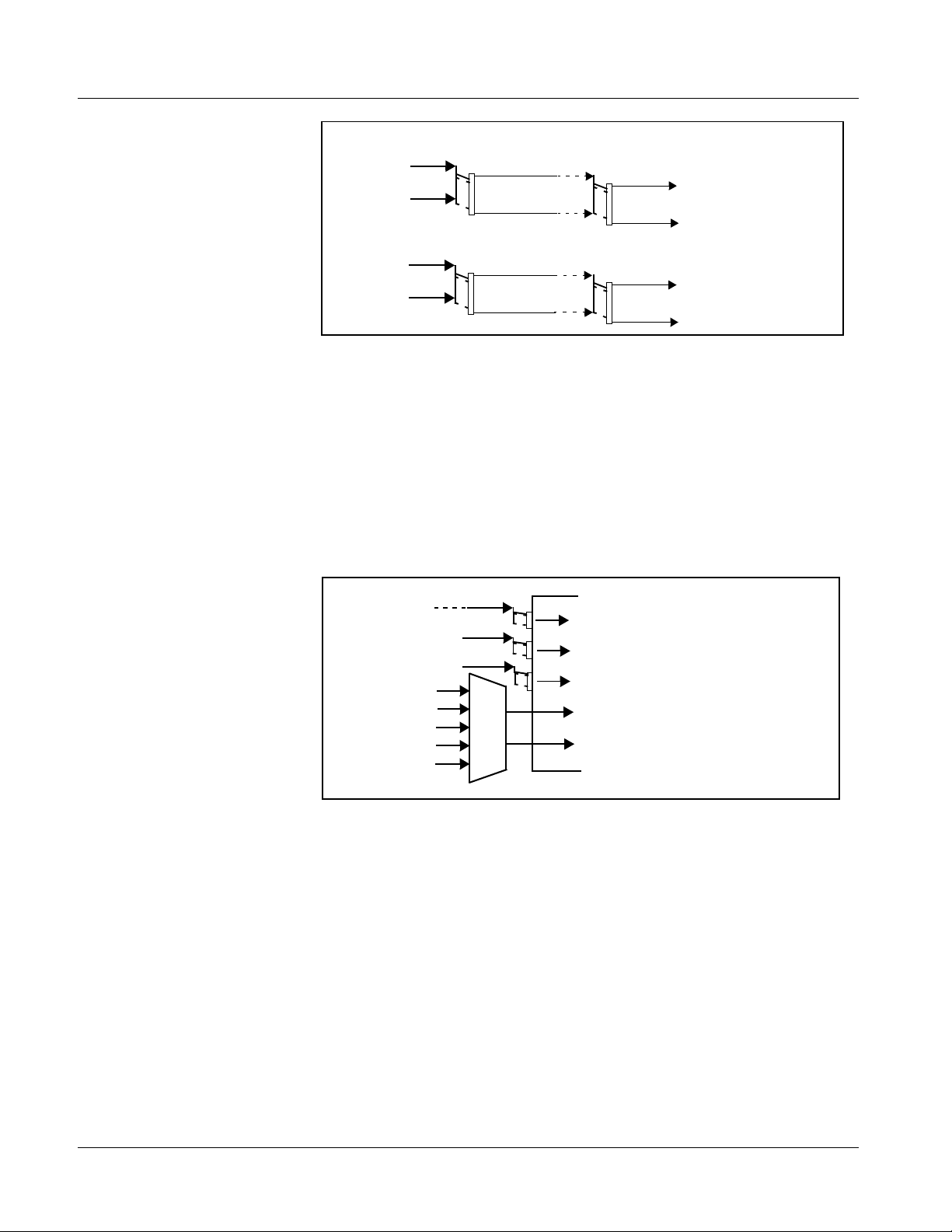
Audio Down Mixer and Mono Mixer Function
(See Figure 1-5.) The Audio Down Mixer function provides for the selection
of any five embedded, AES discrete, or analog audio sources serving as Left
(
L), Right (R), Center (C), Left Surround (Ls), and Right Surround (Rs)
individual signal s to b e multi plexed into a ster eo pair (Down Mix Left (
and Down Mix Right (
turn be routed and processe d just l ike any o f the oth er aud io source s descri bed
earlier.
DM-R)). The resulting stereo pair DM-L and DM-R can in
DM-L)
Embed Ch 1 - Ch 16
AES Ch 1 - Ch 16
AN-AUD Ch 1- Ch 8
Embedded Ch 1
Embedded Ch 2
AES Ch 6
Embedded Ch 4
Embedded Ch 5
Ls
L
C
R
Rs
DM-L
DM-R
Figure 1-5 Audio Mixing Functional Block Diagram with Example Sources
1-14 9061 PRODUCT MANUAL 9061-OM (V4.9)
Page 19
Introduction 9061 Functional Description
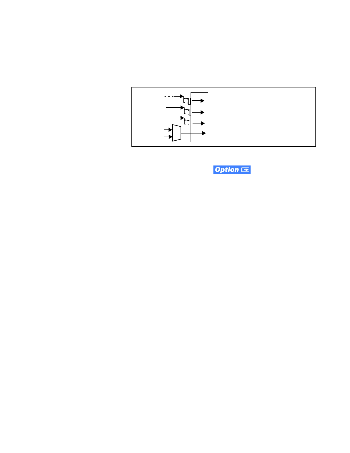
The Mono Mixer function (Figure 1-6) generates an additional mono-mixed
channel from two sel ec ted embed d ed, AES di scr et e, or analog input chann el s
serving as left and ri ght i nputs. Th e resul ting mon o mix chann el
turn be routed a nd process ed just like any of the other au dio sourc es descri bed
earlier.
Emb Ch 1 - Ch 16
AES Ch 1 - Ch 16
AN-AUD Ch 1- Ch 8
MONO can in
Emb Ch 12
Emb Ch 16
Figure 1-6 Audio Mono Mix Functional Block Diagram with Example Sources
L
R
MONO
Σ
2.0-to-5.1 Upmix Function
Note: Upmix function is an optional licensable feature. This function and its controls
appear only when a license key is entered and activated. (This option (identified in Cobalt
field-activated using a key string which is sent to you when this option is purchased.)
The 2.0-to-5.1 upmixer function receives a normal PCM stereo pair fr om the
Audio Routing/Gain Control function and upmixes the pair to provide 5.1
channels (Left (
Surround (
overwrites the six selected channels with the new 5.1 upmix signals
(including replacing the original source stereo
R signals).
The 2.0-to-5.1 upmixer can be set to up mix in any of three modes: Always
upmix, Bypass upmix, or Auto enable/bypass upmixing. The Auto upmixing
mode looks at the sig nal l evels on the sele cted chann els and c ompares th em to
a selectable level threshold. It then determines whether or not to generate 5.1
upmixing from the stereo pair as follows:
®
price lists as +UM) can be purchased upon initial order, or
L), Right (R), Center (C), Low Frequency Effects (LFE), Left
Ls), and Right Surround (Rs)). Whenever the upmixer is active, it
L and R inputs with new L and
• If the upmixer detects signal level below a selected threshold on all
four of the selected channels designated as
C, LFE, Ls, and Rs, this
indicates to the upmixer that these channels are not carrying 5.1. In
this case, the upmixer o verwrites all six selected channels with the
new 5.1 content.
• If the upmixer detects signal level above a selected threshold on any
of the four selected channels designated as
C, LFE, Ls, and Rs, this
indicates to the upmixer that the channel(s) are already carrying
viable 5.1 content. In t his cas e, the upmix er is bypa ssed, al lo wing the
original channels to pass unaffected.
9061-OM (V4.9) 9061 PRODUCT MANUAL 1-15
Page 20
1 9061 Functional Description
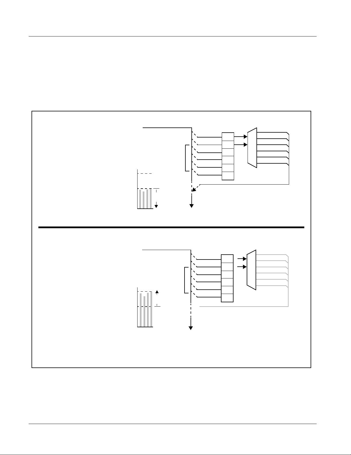
The examples in Figure 1-7 show t he automatic enable/di sable up-mixing
function applied to example selected channels
shown and described, the processing is contingent upon the signal levels of
the channe ls selected to carry the new 5.1 upmix relative to the selected
threshold (in this example, -60 dBFS). Note also that this function is applied
after the Audio Routi ng/Ga in Cont rol f uncti on. Beca use al l aud io inputs pass
through the Audio Routing/Gain Control function before the up mixer, the up
mixer can use embedded, AES discrete, and/or analog audio sources.
From Audio
Routing/Gain
Control
With all detected signal levels on
EmbCh3– Ch 6 below
threshold, upmixer is active and
overwrites with new 5.1.
- 20 dBFS
Emb Ch 1 – Ch 16
>
Emb Ch 1
Emb Ch 2
Emb Ch 3
Emb Ch 4
Emb Ch 5
Emb Ch 6
Threshold
Emb Ch 1 thru Emb Ch 6. As
Detect
L
R
(C)
(LFE)
(Ls)
(Rs)
5.1 Up Mix
L – Emb Ch 1
R – Emb Ch 2
C – Emb Ch 3
LFE – Emb Ch 4
Ls – Emb Ch 5
Rs – Emb Ch 6
- 60 dBFS
From Audio
Routing/Gain
Control
>
With any detected signal levels
on Emb Ch 3 – Ch 6 above
threshold, upmixer is bypassed.
- 20 dBFS
- 60 dBFS
Note: In either case shown here, the unselected
channels (in this example, Emb Ch 7 thru Ch
16) are not involved in this process and always
pass unaffected.
Below Threshold
(Overwrite)
s
s
E
C
L
R
F
L
Emb Ch 1 – Ch 16
Above Threshold
(Bypass)
s
s
E
C
L
R
F
L
To Audio
Embed
To Audio
Embed
Emb Ch 1
Emb Ch 2
Emb Ch 3
Emb Ch 4
Emb Ch 5
Emb Ch 6
X
Selected channels Emb Ch 1 – Ch 6
are overwritten w ith the new 5.1
upmix content.
Threshold
Detect
L
R
(C)
(LFE)
(Ls)
(Rs)
Because the selected channels are
already carrying viable content,
upmixing is bypassed, allowing the
six original Emb Ch 1 – Ch 6 to pass
unaffected.
5.1 Up Mix
X
X
Figure 1-7 Up Mix Auto Enable/Bypass with Example Sources
1-16 9061 PRODUCT MANUAL 9061-OM (V4.9)
Page 21

Introduction 9061 Functional Description
Loudness Processor (Option +LP)
Note: Loudness processor function is an optional licensable feature. This function
and its controls appear only when a license key is entered and activated.
(This option (identified in Cobalt
initial order, or field-activated using a key string which is sent to you when this
option is purchased.)
®
price lists as +LP) can be purchased upon
If your card was purchased with option +LP, loudness processor manual
supplement “5.1 and Stereo Loudness Processing Options for Compass
®
Cards (+LP51, +LP20) Manual Supplement” (OPT-SW-LP-MS) is included
in your documentation package. Supplement OPT-SW-LP-MS can be
downloaded from our website or requested using the Cobalt contact
information in this manual.
Tone Generator Function
The 9061 contains four built-in tone generators (Tone Generator 1 thru Tone
Generator 4). Each of the four tone generators can be set to a diff erent
frequency, and are available as audio sour ce s f or t h e embed ded or AES audio
outputs.
18 discrete sine wave frequencies are a vailable, ranging from 50 Hz to 16 kHz
(default frequency is 1.0 kHz).
Audio Routing Example
Figure 1-8 shows an example of using the 9061 audio embedding/
de-embedding and routing functions to de-embed audio, route the audio to
discrete outputs for post-production processing (in this example, a console
used for post-production EQ, levels, and monitor), and finally re-embed the
audio into the SDI video output. Additionally, the example shows how
external analog and internal tone generator sources can be embedded into the
SDI output (in this exampl e, a provis ion for local station ID voi ce-over analog
and a tone).
Note that the source and destination correlations shown here are only
examples; any source can route to any destination.
9061-OM (V4.9) 9061 PRODUCT MANUAL 1-17
Page 22
1 9061 Functional Description
9061
Post-Production
Video Feed
(with five
embedded audio
channels)
Analog
2-Channel
Voice-Over
Feed
SDI IN
Audio
De-Embed
AN-AUD IN 1
AN-AUD IN 2
Audio Routing/
Control
Analog
Ch 1
Analog
Ch 2
Embed Ch 1
Embed Ch 2
Embed Ch 3
Embed Ch 4
Embed Ch 5
TG1
AES Ch 1
AES Ch 2
AES Ch 3
AES Ch 4
AES Ch 5
AES Ch 6
AES Ch 7
AES Ch 8
Audio
Embed
AES OUT 1
AES OUT 2
AES OUT 4
SDI OUT
AES OUT 3
OTA Video
Feed (with
eight embedded
audio channels)
AES IN 5
AES IN 6
AES IN 7
AES IN 8
AES Ch 9
AES Ch 10
AES Ch11
AES Ch 12
AES Ch 13
AES Ch 14
AES Ch 15
AES Ch 16
Silence
Embed Ch 1
Embed Ch 2
Embed Ch 3
Embed Ch 4
Embed Ch 5
Embed Ch 6
Embed Ch 7
Embed Ch 8
Embed Ch 9 –
Embed Ch 16
Post-Production Console
Figure 1-8 Audio Routing Example
1-18 9061 PRODUCT MANUAL 9061-OM (V4.9)
Page 23

Introduction 9061 Functional Description
AES Audio Input Advanced Features
AES Sample Rate Converter
The 9061 AES inputs have sample rate converters that can be independently
enabled for each AES pair to allow the card to interface with asynchronous
AES sources (sources in which AES timing does not match the video input
timing). The sample rate converters are set to disabled (bypassed) by default;
this is necessary when embedding non-PCM AES audio such as Dolby
®
Dolby
Digital au dio streams. When a valid Dolby® E or Dolby® Digital
signal (in accordance with SMPTE 337M) is detected on an AES or
embedded audio signal, SRC is automatically bypassed along with gain and
polarity controls.
Zero-Delay Audio Embedding
®
E or
In cases where additiona l delay must be avoided, it may be desirable to e mbed
AES with minimum latency. For example if Dolby
®
E is to be embedded into
video with no latency, additional delay may not be t olerable. Usin g zero-delay
embedding, the video can then be delayed by one frame to account for the
Dolby E encoding delay. In this manner, any delay between video and audio
can be cleanly contained within one frame period.
When zero-delay audio emb edding is en abled for a give n AES pair , th e pair is
directly embedded int o its corres ponding group (for example , AES Pair 1 in to
embedded channels 1 an d 2; AES Pai r 2 int o embedde d channe ls 3 an d 4, a nd
so on) with the normal frame sync audio delay being bypassed.
This function overrides the audio routing sys tem (for example if AES Pair 1 is
selected, then the controls to route AES Pair 1 into other embedded channels
will not apply). Gain and polarity control is not available when this option is
selected. Zero-delay audio embedding is set to Off by default.
Low-Latency AES Passthrough
This function is similar to zero-delay audio embedding. If low-latency AES
passthrough is selected for a given input pair, it causes the corresponding
AES output pair to act as a bit-for-bit copy of the corresponding AES input
pair.
This control overrides the normal audio routing and delay. Gain and polarity
control is not available when this option is selected. Passthrough is set to Off
by default.
9061-OM (V4.9) 9061 PRODUCT MANUAL 1-19
Page 24
1 9061 Functional Description
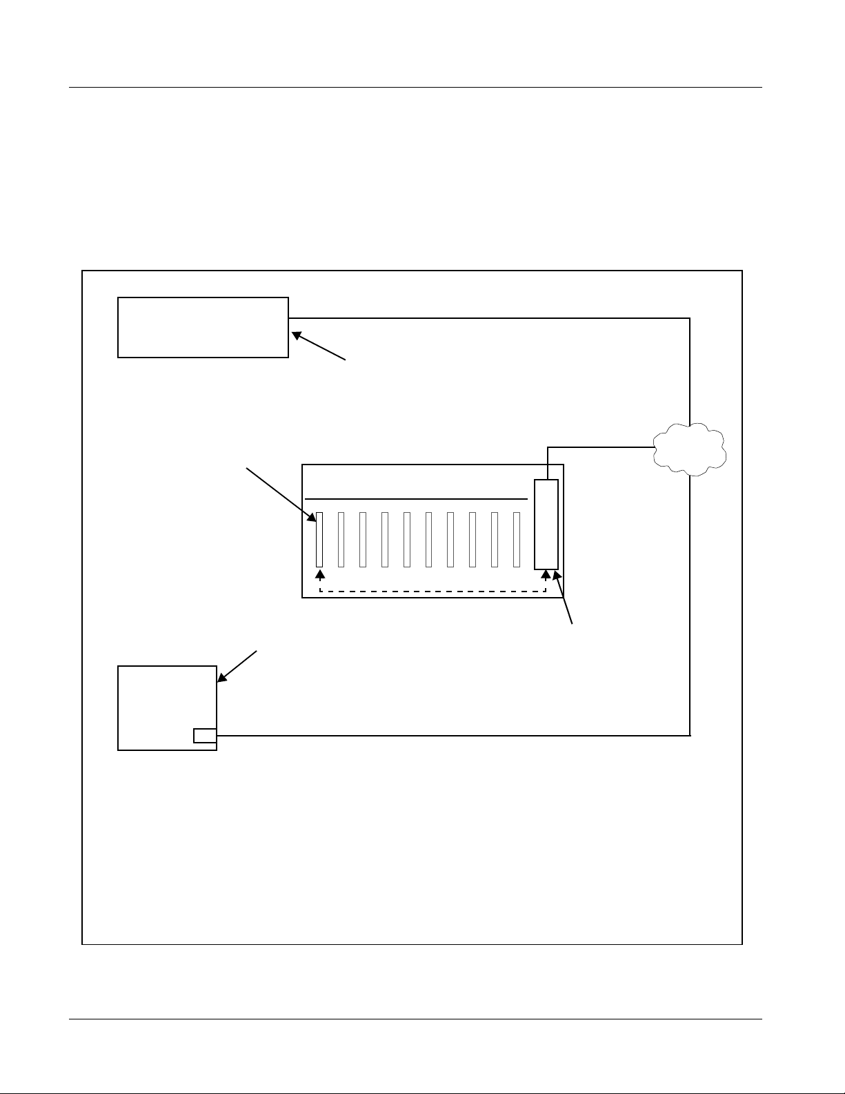
User Control Interface
Figure 1-9 shows the user control interface options for the 9061. These
options are individually described below.
Note: All user control interfaces described here are cross-compatible and can oper-
ate together as desired. Where applicable, any control setting change made
using a particular user interface is reflected on any other connected interface.
OGCP-9000 Control Panel
OGCP-9000/CC Control Panel
Card Edge Controls
9061 card can be
controlled using built-in
card edge controls
Computer
with NIC
or
DashBoard™ Remote Control
Using a computer with
DashBoard™ installed, 9061
card can be remotely controlled
over a LAN
Remote Control Panel
Using the Control Panel,
9061 card can be remotely
controlled over a LAN
LAN
20-Slot Frame with MFC-8320-N network
controller card
In conjunction with a frame equipped
with an MFC-8320-N network
controller card, 9061 card can be
remotely controlled over a LAN
Note: • To communicate with DashBoard™ or a Remote Control Panel, the frame must have the optional
MFC-8320-N network controller card installed.
• DashBoard™ and the Remote Control Panels provide network control of the 9061 as shown. The
value displayed at any time on the card, or via DashBoard™ or a Control Panel is the actual value
as set on the card, with the current value displayed being the actual value as effected by the card.
Parameter changes made by any of these means are universally accepted by the card (for
example, a change made using the card edge controls will change the setting displayed on
DashBoard™ and a Control Panel; a change made using DashBoard™ will similarly change the
setting displayed on a Control Panel and the card itself).
Figure 1-9 9061 User Control Interface
1-20 9061 PRODUCT MANUAL 9061-OM (V4.9)
Page 25

Introduction 9061 Functional Description
• Built-in Card Edge User Interface – Using the built-in card edge
controls and display, card control settings can be set using a front
panel menu which is described in Chapter 3,“Operat ing Inst ruction s”.
Note: Some of the 9061 functions described in this manual are available only when
using the DashBoard™, or Cobalt
Control Panel user interfaces.
• DashBoard™ User Interface – Using DashBoard™, the 9061 and
other cards installed in openGear®
®
OGCP-9000 or OGCP-9000/CC Remote
1
frames such as the Cobalt®
HPF-9000 or 8321 Frame can be controlled from a computer and
monitor.
DashBoard™ allows users to view all frames on a network with
control and monitoring for all populated slots inside a frame. This
simplifies the setup and use of numerous modules in a large
installation and offers the ability to centralize monitoring. Cards
define thei r controllable parameters to DashBoard™, so the control
interface is always up to date.
The DashBoard™ software can be downloaded from the Cobalt
Digital Inc. website: www.cobaltdigital.com
(enter “DashBoard” in
the search window). The DashBoard™ user interfa ce is describe d in
Chapter 3,“Operating Instructions”.
Note: If network remote control is to be used for the frame and the frame has not yet
been set up for remote control, Cobalt
User Guide (PN 9000RCS-RM) provides thorough information and
step-by-step instructions for setting up network remote control of COMPASS
cards using DashBoard™. (Cobalt
Remote Control Panel product manuals have complete instructions for setting
up remote control using a Remote Control Panel.)
Download a copy of this guide by clicking on the Support>Documents>
Reference Guides link at www.cobaltdigital.com and then select DashBoard
Remote Control Setup Guide as a download, or contact Cobalt
Contact Cobalt Digital Inc. (p. 1-30).
®
reference guide Remote Control
®
OGCP-9000 and OGCP-9000/CC
®
as listed in
®
• Cobalt
®
OGCP-9000, OGCP-9000/CC and WinOGCP Remote
Control Panels – The OGCP-9000, OGCP-9000/CC, and WinOGCP
Remote Control Panels conveniently and intuitively provide
parameter monitor and control of the cards within the 20-slot frame.
The remote control panels allow quick and intuitive access to
hundreds of cards in a facility, and can monitor and allow adjustment
of multiple parameters at one time.
The remote contro l panels are totally compatible with the openGear
®
control software DashBoard™; any changes made with either system
are reflected on the oth er.
1. openGear® is a registered trademark of Ross Video Limited. DashBoard™ is a trademark of Ross
Video Limit e d .
9061-OM (V4.9) 9061 PRODUCT MANUAL 1-21
Page 26
1 9061 Functional Description
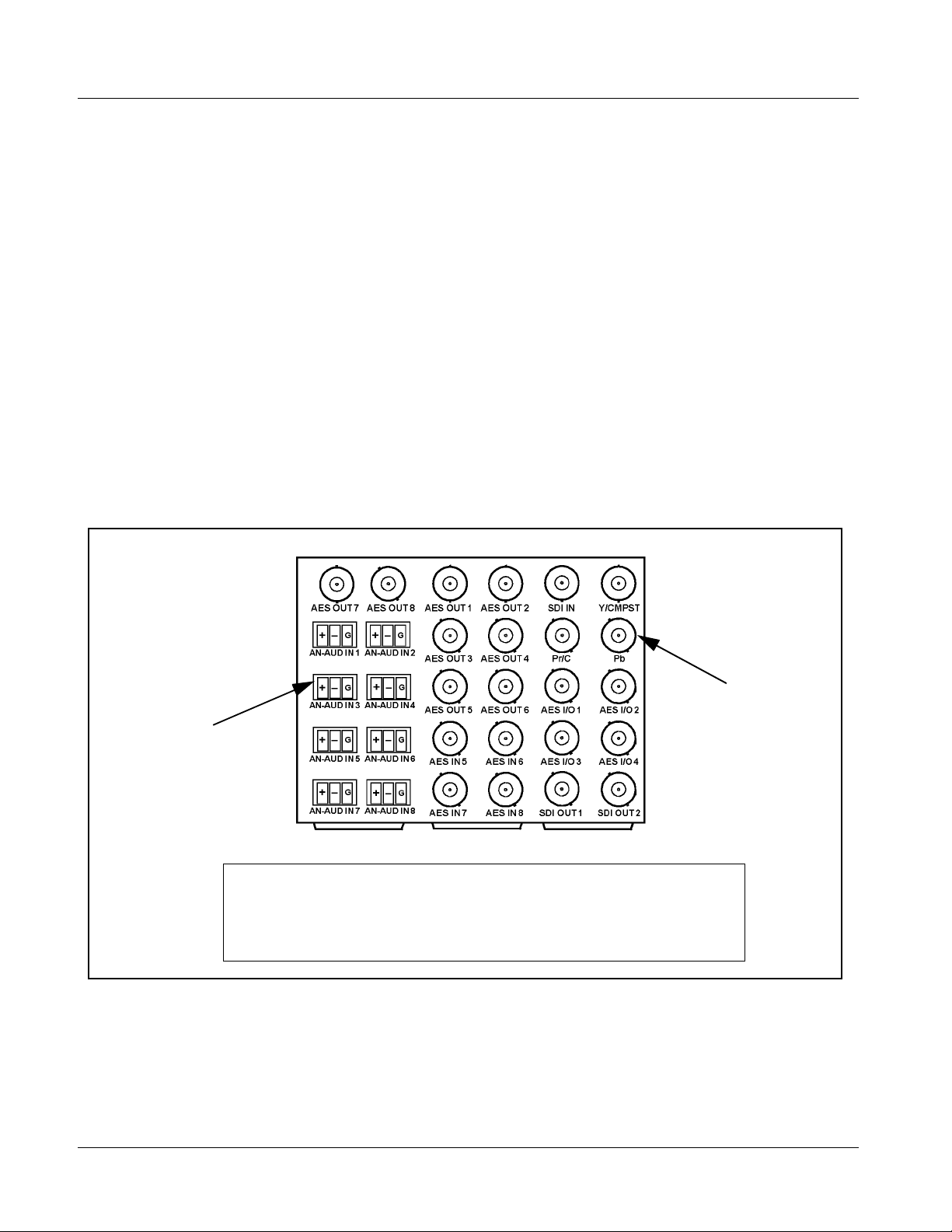
9061 Rear I/O Modules
The 9061 physically inter faces to sys tem video and audi o connectio ns using a
Rear I/O Module. Figure 1-10 shows a typical 9061 Rear I/O Module.
All inputs and outputs shown in the 9061 Functional Block Diagram (Figure
1-1) enter and exit the card via the card edge backplane connector. The
Rear I/O Module breaks out the 9061 card edge connections to industry
standard connecti ons tha t int er face with other components and systems in the
signal chain.
In this manner, the particular inputs and outputs required for a particular
application can be acc ommodated using a Rear I/O Module tha t be st sui ts the
requirements. The required input and outputs are broken out to the industry
standard connectors on the Rear I/O Module; the unused inputs and outputs
remain unterminated and not available for use.
The full assortment of 9061 Rear I/O Modules is shown and described in
9061 Rear I/O Modules (p. 2-6) in Chapter 2, “Installation and Setup”.
3-wire Phoenix terminal block
connectors for balanced
analog audio signals
In this example, an RM-9061-G Rear I/O Module provides a connection interface for the
signal types shown here.
Rear I/O Modules RM-9061-A through RM-9061-F offer other options particularly suited to
various requirements.
BNC connectors for coaxial
video and AES audio signals
Figure 1-10 Typical 9061 Rear I/O Module
1-22 9061 PRODUCT MANUAL 9061-OM (V4.9)
Page 27
Introduction 9061 Functional Description
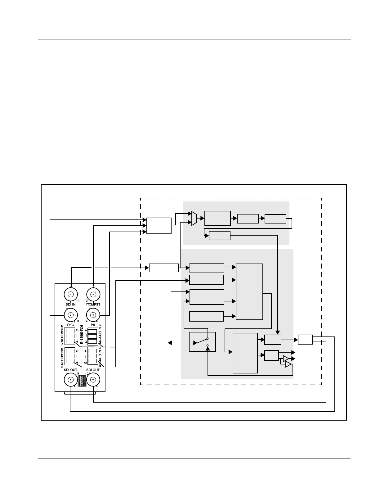
Figure 1-11 s hows a 9061 car d using an RM-9061-B Rear I/O Module. Usi ng
this Rear I/O Module, this module provides industry standard break-out
connections for the following inputs and outputs required by this application:
• Inputs:
• HD/SD SDI IN – dual-rate HD/SD-SDI input
• Y/Cmpst IN, Pr/C IN, Pb IN – analog composite/component video
inputs
• AN-AUD IN (1-4) – balanced analog audio inputs (i npu ts 5-8 unused)
• Outputs:
• SDI OUT – HD/SD-SDI buffered video outputs
The other 9061 inputs and outputs not accommodated by this Rear I/O
Module (shown in gray in Figure 1-11) remain unterminated.
Pr/C IN
Y/Cmpst IN
Pb IN
HD/SD
SDI IN
AN-AUD
IN (1-4)
AES IN (5-8)
AES I/O
(1-4)
Video Processor
Audio Processor
9061
AES OUT
(5-8)
(1-4)
SDI OUT
Figure 1-11 9061 with RM-9061-B Rear I/O Module
9061-OM (V4.9) 9061 PRODUCT MANUAL 1-23
Page 28

1 9061 Functional Description
Audio and Video Formats Supported by the 9061
The 9061 supports all current SMPTE standard SD and HD video formats.
Table 1-2 lists and provides details regarding the audio and video formats
supported by the 9061.
Table 1-2 Supported Audio and Video Formats
Item Description/Specification
Input / Output Video Raster Structure: Frame Rate:
1080PsF 23.98; 24
1080p 23.98; 24
(1)
1080i
720p 23.98
25; 29.97; 30
(2)
; 24
(2)
; 25; 29.97; 30; 50;
59.94; 60
(1)
486i
575i
(1)
29.97
25
Embedded Audio The 9061 supports all four groups (16 channels) of embedded audio at
full 24-bit resolution in both SD (with extended data packets) and HD.
Analog Audio The 9061 supports 8 channels of balanced (differential) analog audio.
The analog audio is encoded such that a +24 dBu input is equivalent to
digital 0 dB F S.
Discrete AES Audio Input The 9061 can accept 16 channels (8 pairs) of discrete AES audio on
75Ω BNC connections. Sample rate conversion can be employed to
account for minor clock rate differences in the AES stream and the
input video stream.
Note: The AES signal must have a nominal rate of approximately
48 kHz. The 9061 does not support AES input at 32 kHz,
44.1 kHz, 96 kHz or 192 kHz rates.
Discrete AES Audio Output The 9061 can provide 16 channels (8 pairs) of discrete AES audio on
75Ω BNC connections.
(1) All rates displayed as frame rates; interlaced (“i”) field rates are two times the rate value shown.
(2) Not supported as analog video input formats.
1-24 9061 PRODUCT MANUAL 9061-OM (V4.9)
Page 29

Introduction Technical Specifications
Technical Specifications
Table 1-3 lists the technical specifications for the 9061 card.
Table 1-3 Technical Specifica tions
Item Characteristic
Part number, nomenclature 9061 Up/Down/Cross Converter with Analog/SDI Input, Audio
Embed/De-Embed, Frame Sync, Timecode, and Closed Caption
Support
Installation/usage environment Intended for installation and usage in frame meeting openGear™
modular system definition.
Power consumptio n < 24 Watts maximum
Environmental:
Operating temperature:
Relative humidity (operating or storage):
Frame communication 10/100 Mbps Ethernet with Auto-MDIX.
32° – 104° F (0° – 40° C)
< 95%, non-condensing
Indicators Card edge display and indicators as follows:
• 4-character alphanumeric display
• Status/Error LED indicator
• Input For mat LED indic ato r
Controls Card edge switches as follows:
• Menu Enter pushbutton switch
• Menu Exit pushbutton switch
• Up/down selection toggle switch
Internal Tone Generators Four built-in tone generators, each configurable for 18 discrete
sine wave frequencies ranging from 50 Hz to 16 kHz.
Generator source signal level is equivalent to -20 dBu.
A/D Process HD: 4:4:4
SD: 8:8:8
Resolution: 12-bit A/D and 10-bit video data path
SD Comb Filter: 5-line adaptive
Serial Digital Video Input Data Rates Supported:
SMPTE 292 HD-SDI: 1.485 Gbps or 1.485/1.001 Gbps
SMPTE 259M-C SD-SDI: 270 Mbps
Impedance:
75 Ω terminating
Equalization (HD):
328 ft (100 m) Belden 1694A
9061-OM (V4.9) 9061 PRODUCT MANUAL 1-25
Page 30

1 Technical Specifications
Table 1-3 Technical Specifications — continued
Item Characteristic
Serial Digital Video Input (cont.) Equalization (SD):
1000 ft (305 m) Belden 1694A
Return Loss:
> 15 dB at 5 MHz – 1.485 GHz
Analog Video Input Input Complement:
Separate component Y/composite, Pr/C, and Pb inputs
Input Type:
Differential; Common Mode Rejection = 5 VAC
Video Input Types:
HD: Component YPbPr and RGB SMPTE
SD: Composite, Component YPbPr (BetaCam™, MII™,
SMPTE/N10), RGB, and Y/C
Conversion Bit Depth:
12 bits
SD Color Separation:
5-Line Adaptive Comb or Notch Filter
Frequency Response (HD):
Y: 0 – 25 MHz ± 0.3 dB
Pb/B: 0 – 13.5 MHz ± 0.3 dB
Pr/R: 0 – 13.5 MHz ± 0.3 dB
Frequency Response (SD):
0 – 5.2 MHz ± 0.25dB
Differential Phase (SD):
< ± 0.4° typical
Differential Gain (SD):
< ± 0.4% typical
Analog Front-End Crosstalk:
Within noise floor measurement
Return Loss:
> 20 dB to 30 MHz
Serial Digital Video Outputs Number of Outputs:
Two HD/SD-SDI BNC per IEC 60169-8 Amendment 2
Impedance:
75 Ω
1-26 9061 PRODUCT MANUAL 9061-OM (V4.9)
Page 31

Introduction Technical Specifications
Table 1-3 Technical Specifica tions — continued
Item Characteristic
Serial Digital Video Outputs (cont.) Return Loss:
> 15 dB at 5 MHz – 270 MHz
> 12 dB at 270 MHz – 1.485 GHz
Signal Level:
800 mV ± 10%
DC Offset:
0 V ± 50 mV
Jitter (HD ):
< 0.15 UI (all outputs)
Jitter (SD ) :
< 0.10 UI (all outputs)
Overshoot:
< 0.2% of amplitude
AES Audio Input Standard:
SMPTE 276M
Number of Inputs (maximum):
8 unbalanced
Input Level:
0.1 to 2.5 Vp-p (5 Vp-p tolerant)
Input Impedance:
75 Ω
Return Loss:
> 12 dB at 100 kHz to 6 MHz
Resolution:
24-bit only
Sample Rate:
48 kHz
SRC:
32-channel; 142 dB S/N
AES Audio Output Standard:
SMPTE 276M
Number of Outputs (maximum):
8 unbalanced
Output Impedance:
75 Ω
9061-OM (V4.9) 9061 PRODUCT MANUAL 1-27
Page 32

1 Technical Specifications
Table 1-3 Technical Specifications — continued
Item Characteristic
AES Audio Output (cont.) Return Loss:
> 30 dB 100 kHz to 6 MHz
Sample Rate:
48 kHz
Analog Audio Input Number of Inputs (maximum):
Eight, 3-wire balanced analog audio using Phoenix connectors
with removable screw terminal blocks (Phoenix PN 1803581;
Cobalt PN 5000-0013-000R)
Sampling Rate:
48 kHz (locked to video input)
Signal Level:
+24 dBu => 0 dBFS
A/D Frequency Response:
20 – 20 kHz ± 0.25 dB
Audio/RS-485 LTC Support
(+LTC option only)
®
Dolby
Reference Video Input Number of Inputs:
RS485 Metadata Output Metadata extracted from input video (per SMPTE 2020-1-2008) on
Balanced analog audio or AES/embedded PCM equivalent
conforming to SMPTE 12M-1; § 9.6; RS-485 LTC
RS-485 interface; 3-wire balanced via Phoenix terminal block
connector.
Two non-terminating (looping) Frame Reference inputs
Standards Supported (HD):
720p 24; 25; 29.97; 30; 50; 59.94
1080i 25; 29.97
1080p 23.98; 24; 25; 29.97; 30
1080p/sF 23.98; 24
Standards Supported (SD):
486i 29.97 (NTSC)
575i 25 (PAL)
Signal Level:
1 Vp-p nominal
Signal Type:
Analog video sync (black burst or tri-level)
Impedance:
75 Ω
Return Loss:
> 30 dB to 30 MHz
Allowable Maximum DC on Ref Input:
±1.0 V
1-28 9061 PRODUCT MANUAL 9061-OM (V4.9)
Page 33

Introduction Warranty and Service Information
Warranty and Service Information
Cobalt Digital Inc. Limited Warranty
This product is warranted to be free from defects in material and workmanship for a period of five (5)
years from the date of shipment to the original purchaser, except that 4000, 5000, 6000, 8000 series
power supplies, and Dolby
material and workmanship for a period of one (1) year.
Cobalt Digital Inc.'s (“Cobalt”) sole obligation under this warranty shall be limited to, at its option, (i)
the repair or (ii) replacement of the produc t, and the det ermination of whether a defect is covered under
this limited warranty shall be made at the sole discretion of Cobalt.
This limited warrant y appl ies on ly t o the origi nal end-pu rchaser of the produ ct, and i s not assign able o r
transferrable therefrom. This warr ant y i s li mited to defects in material and workmanship, and shall not
apply to acts of God, accidents, or negligence on behalf of the purchaser, and shall be voided upon the
misuse, abuse, alteration, or modification of the product. Only Cobalt authorized factory
representatives are authorized to make repairs to the product, and any unauthorized attempt to repair
this product shall immediately void the warranty. Please contact Cobalt Technical Support for more
information.
®
modules (where applicable) are warranted to be free from defects in
To facilitate the resol ution of warranty related issue s , Cobalt recommends registering the product by
completing and returning a product registration form. In the event of a warrantable defect, the
purchaser shall notify Cobalt with a descripti on of the problem, and Cobalt shall p rovi de t he pur ch aser
with a Re turn Mate rial Auth oriz ation (“RMA”). For retu rn, defective product s should be double boxed,
and sufficiently protecte d, in the original packa ging, or equivalent, a nd shipped to the Coba lt Factory
Service Center, postage prepaid and insured for the purchase price. The purchaser should include the
RMA number, description of the problem encountered, date purchased, name of dealer purchased
from, and serial number with the shipment.
Cobalt Digital Inc. Factory Service Center
2406 E. University Avenue Office: (217) 344-1243
Urbana, IL 61802 USA Fax: (217) 344-1245
www.cobaltdigital.com Email : info @cobaltdigital.com
THIS LIMITED WARRANTY IS EXPRESSLY IN LIEU OF ALL OTHER WARRANTIES
EXPRESSED OR IMPLIED, INCLUDING THE WARRANTIES OF MERCHANTABILITY AND
FITNESS FOR A PARTICULAR PURPOSE AND OF ALL OTHER OBLIGATIO N S OR
LIABILITIES ON COBALT'S PART. ANY SOFTWARE PROVIDED WITH, OR FOR USE WITH,
THE PRODUCT IS PROVIDED “AS IS.” THE BUYER OF THE PRODUCT ACKNOWLEDGES
THAT NO OTHER REPRESENTATIONS WERE MADE OR RELIED UPON WITH RESPECT TO
THE QUALITY AND FUNCTION OF THE GOODS HEREIN SOLD. COBALT PRODUCTS ARE
NOT AUTHORIZED FOR USE IN LIFE SUPPORT APPLICATIONS.
COBALT'S LIABILITY, WHETHER IN CONTRACT, TORT, WARRANTY, OR OTHERWISE, IS
LIMITED TO THE REPAIR OR REPLACEMENT, AT ITS OPTION, OF ANY DEFECTIVE
PRODUCT, AND SHALL IN NO EVENT INCLUDE SPE CIAL, INDIRECT, INCIDENTAL, OR
CONSEQUENTIAL DAMAGES (INCLUDING LOST PROFITS), EVEN IF IT HAS BEEN
ADVISED OF THE POSSIBILITY OF SUCH DAMAGES.
9061-OM (V4.9) 9061 PRODUCT MANUAL 1-29
Page 34

1 Contact Cobalt Digital Inc.
Contact Cobalt Digital Inc.
Feel free to contact our thorough and professional support representatives fo r
any of the following:
• Name and address of your local dealer
• Product information and pricing
• Technical support
• Upcoming trade show information
Phone: (217) 344-1243
Fax: (217) 344-1245
Web: www.cobaltdigital.com
General Information: info@cobaltdigital.com
Technical Support: support@cobaltdigital.com
1-30 9061 PRODUCT MANUAL 9061-OM (V4.9)
Page 35

Overview
Chapter 2
Chapter 2 Installation and Setup
This chapter contains the following information:
• Setting I/ O Switches for AES I/O (1-4) Ports (p. 2-1)
• Installing the 9061 Into a Frame Slot (p. 2-2)
• Installing a Rear I/O Module (p. 2-4)
• Setting Up 9061 Network Remote Control (p. 2-10)
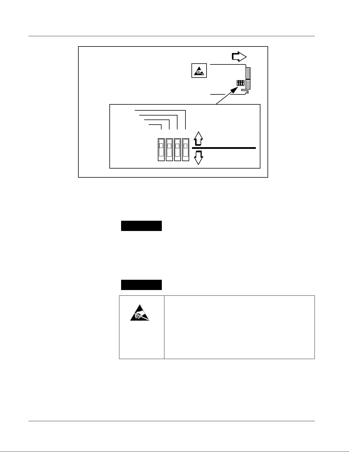
Setting I/O Switches for AES I/O (1-4) Ports
Note: This procedure is applicable only if any of the four AES I/O (1-4) ports on the
9061 are to be used as outputs (the switches are set to input mode by factory
default). The 9061 is equipped with a four-section red DIP switch that sets
AES pairs 1 thru 4 as either inputs or outputs. The factory default position is
the input position for each pair.
• If all of the AES I/O (1-4) ports are to be used as inputs (or not used at all),
omit this procedure.
• If any of the AES I/O (1-4) ports are to be used as outputs, set the switches
as described in this procedure.
Note switch S11 thru S14 settings for AES I/O 1 thru AES I/O 4 mode shown
in Figure 2-1. For p ort to be used as an output, set switch to down position as
shown in Figure 2-1.
Note: Regardless of S11 thru S14 settings for AES I/O 1 thru AES I/O 4, outputs
AES OUT (1-8) are still available on cards equipped with a Rear I/O Module
having dedicated A E S OU T (1 -8) BNC connectors.
9061-OM (V4.9) 9061 PRODUCT MANUAL 2-1
Page 36
2 Installing the 9061 Into a Frame Slot
Rear of Card
AES I/O 4
AES I/O 3
AES I/O 2
AES I/O 1
S11S12S13S14
••••
Figure 2-1 9061 AES I/O (1-4) Mode Switches
Installing the 9061 Into a Frame Slot
CAUTION
Heat and power distribution requirements within a frame may dictate specific
slot placement of cards. Cards with many heat-producing components should
be arranged to avoid areas of excess heat build-up, particularly in frames
using only convection cooling. The 9061 has a moderate power dissipation
(24 W max.). As such, avoiding placing the card adjacent to other cards with
similar dissipation values if possible.
CAUTION
INPUT MODE
(Factory Default)
OUTPUT MODE
This device contains semiconductor devices which are
susceptible to serious damage from Electrostatic
Discharge (ESD). ESD damage may not be immediately
apparent and can affect the long-term reliability of the
device.
Avoid handling circuit boards in high static environments
such as carpeted areas, and when wearing synthetic fiber
clothing. Always use proper ESD handling precautions
and equipment when working on circuit boards and
related equipment.
2-2 9061 PRODUCT MANUAL 9061-OM (V4.9)
Page 37

Installation and Setup Installing the 9061 Into a Frame Slot
Note: • If installing the 9061 in an 8310-C-BNC or 8310-BNC frame (which is
pre-equipped with a 100-BNC rear I/O module installed across the entire
backplane) or a slot already equipped with a suitable I/O module, proceed to
card installation steps below.
• If installing the 9061 in a a slot with no rear I/O module, a Rear I/O Mod-
ule is required before cabling can be connected. Refer to Installing a
Rear I/O Module (p. 2-4) for rear I/O module installation procedure.
CAUTION
If required, make certain Rear I/O Module(s) is installed before installing the
9061 into the frame slot. Damage to card and/or Rear I/O Module can occur if
module installation is attempted with card already installed in slot.
Note: Check the packaging in which the 9061 was shipped for any extra items such
as a Rear I/O Module connection label. In some cases, this label is shipped
with the card and to be installed on the Rear I/O connector bank corresponding to the slot location of the card.
Install the 9061 into a frame slot as follows:
1. Determine the slot in which the 9061 is to be installed.
2. Open the frame front access panel.
3. While holding the card by the card edges, align the card such that the
plastic ejector tab is on the bottom.
4. Align the card with the top and bottom guides of the slot in which the
card is being installed.
5. Gradually slide the card into the slot. When resistance is noticed, gently
continue pushing the card until its rear printed circuit edge terminals
engage fully into the rear I/O module mating connector.
CAUTION
If card resists fully engaging in rear I/O module mating connector, check for
alignment and proper insertion in slot tracks. Damage to card and/or rear I/O
module may occur if improper card insertion is attempted.
Verify that the card is fully engaged in rear I/O module mating connector.
6.
7. Close the frame front access panel.
8. Connect the input and output cables in accordance with the appropriate
diagram shown in Table 2-1, “9061 Rear I/O Modules” (p. 2-6).
9. Repeat steps 1 through 8 for other 9061 cards.
9061-OM (V4.9) 9061 PRODUCT MANUAL 2-3
Page 38

2 Installing a Rear I/O Module
Note: External frame sync reference signals are received by the card over a refer-
ence bus on the card frame, and not on any card rear I/O module connectors.
The frame has BNC connectors labeled REF 1 and REF 2 which receive the
reference signal from an external source such as a house distribution.
Note: The 9061 BNC inputs are internally 75-ohm terminated. It is not necessary to
terminate unused BNC inputs or outputs.
Note: To remove a card, press down on the ejector tab to unseat the card from the
rear I/O module mating connector. Evenly draw the card from its slot.
10. If network rem ote control is to be used for the fram e and the frame has
not yet been set up for remote control, perform setup in accordance with
Setting Up 9061 Network Remote Control (p. 2-10).
Note: If installing a card in a frame already equipped for, and connected to
DashBoard™, no network setup is required for the card. The card will be discovered by DashBo ard™ and be ready for use.
Installing a Rear I/O Module
Note: This procedure is applicable only if a Rear I/O Module is not currently
installed in the slot where the 9061 is to be installed.
The full assortment of 9061 Rear I/O Modules is shown and described in
9061 Rear I/O Modules (p. 2-6). Install a Rear I/O Module as follows:
1. On the frame, determine the slot in which the 9061 is to be installed.
2. In the mounting area corresponding to the slot location, install
Rear I/O Module as shown in Figure 2-2.
2-4 9061 PRODUCT MANUAL 9061-OM (V4.9)
Page 39

Installation and Setup Installing a Rear I/O Module
Align and engage mounting tab on Rear
I/O Module with the module seating slot
1
on rear of frame chassis.
DSCN3483A.JPG
Hold top of Rear I/O Module flush against
frame chassis and start the captive screw.
2
Lightly tighten captive screw.
Note: Rear I/O Modules RM20-9061-C thru RM20-9061-F occupy
two rear module slot mounting locations and use two captive
screws.
Rear I/O Module RM20-9061-G occupies three rear module
slot mounting locations and uses three captive screws.
DSCN3487A.JPG
Figure 2-2 Rear I/O Module Installation
9061-OM (V4.9) 9061 PRODUCT MANUAL 2-5
Page 40
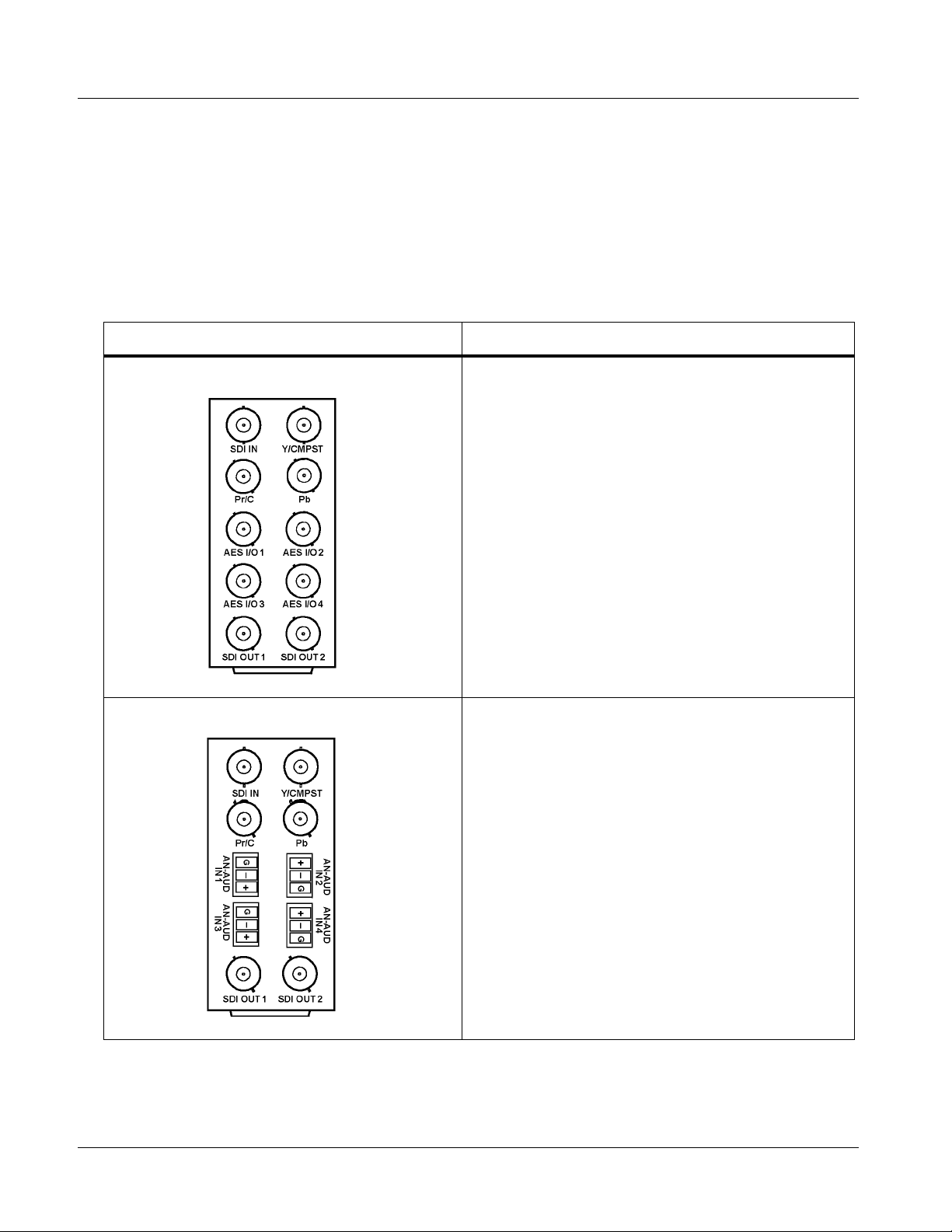
2 Installing a Rear I/O Module
9061 Rear I/O Modules
Table 2-1 shows and describes the full assortment of Rear I/O Modules
specifically for use with the 9061.
Notes: • Rear I/O Modules equipped with 3-wire Phoenix connectors are supplied
with removable screw terminal block adapters. For clarity, the adapters are
omitted in the drawings below.
Table 2-1 9061 Rear I/O Modules
9061 Rear I/O Module Description
RM20-9061-A Provides the following conne cti on s:
• HD/SD-SDI coaxial input (SDI IN)
• Analog Y/composite, Pr/C, and Pb coaxial inputs
(Y/Cmpst, Pr/C, and Pb, respectively)
• Four AES I/O coaxial input/outputs (AES I/O 1 thru
AES I/O 4; I/O function of each connection is
user-configurable)
• Two buffered SDI coaxial outputs (SDI OUT)
RM20-9061-B Provides the following conne cti on s:
• HD/SD-SDI coaxial input (SDI IN)
• Analog Y/composite, Pr/C, and Pb coaxial inputs
(Y/Cmpst, Pr/C, and Pb, respectively)
• Four analog balanced audio inputs (AN-AUD IN 1
thru AN-AUD IN 4)
• Two buffered SDI coaxial outputs (SDI OUT)
2-6 9061 PRODUCT MANUAL 9061-OM (V4.9)
Page 41

Installation and Setup Installing a Rear I/O Module
Table 2-1 9061 Rear I/O Modules — continued
9061 Rear I/O Module Description
RM20-9061-C Provides the following connections:
• HD/SD-SDI coaxial input (SDI IN)
• Ana lo g Y/co mpo si te, Pr /C, and Pb co axi al inputs
(Y/Cmpst, Pr/C, and Pb, respectively)
• Four AES I/O coaxial input/outputs (AES I/O 1 thru
AES I/O 4; I/O function of each connection is
user-configurable)
• Two dedicated AES coaxial audio inputs (AES IN 5
and AES IN 6)
• Eight analog balanced audio inputs (AN-AUD IN 1
thru AN-AUD IN 8)
• Two buffered SDI coaxial outputs (SDI OUT)
RM20-9061-D Provides the following connections:
• HD/SD-SDI coaxial input (SDI IN)
• Four AES I/O coaxial input/outputs (AES I/O 1 thru
AES I/O 4; I/O function of each connection is
user-configurable)
• Four dedicated AES coaxial audio inputs (AES IN 5
thru AES IN 8)
• Eight dedicated AES coaxial audio outputs
(AES OUT 1 thru AES OUT 8)
• Two buffered SDI coaxial outputs (SDI OUT)
Note: AES OUT 1 thru AES OUT 4 on
RM20-9061-D Rear I/O Module always
function as outputs regardless of whether AES
I/O 1 thru AES I/O 4 are used as inputs or
outputs.
9061-OM (V4.9) 9061 PRODUCT MANUAL 2-7
Page 42

2 Installing a Rear I/O Module
Table 2-1 9061 Rear I/O Modules — continued
9061 Rear I/O Module Description
Provides the following conne cti on s:
RM20-9061-E
• HD/SD-SDI coaxial input (SDI IN)
• Analog Y/composite, Pr/C, and Pb coaxial inputs
(Y/Cmpst, Pr/C, and Pb, respectively)
• Four AES I/O coaxial input/outputs (AES I/O 1 thru
AES I/O 4; I/O function of each connection is
user-configurable)
• Four dedicated AES coaxial audio inputs (AES IN 5
thru AES IN 8)
• Six dedicated AES coaxial audio outputs
(AES OUT 1 thru AES OUT 6)
• Two buffered SDI coaxial outputs (SDI OUT)
Note: AES OUT 1 thru AES OUT 4 on
RM20-9061-E Rear I/O Module always
function as outputs regardless of whether AES
I/O 1 thru AES I/O 4 are used as inputs or
outputs.
RM20-9061-F Provides the following conne cti on s:
• HD/SD-SDI coaxial input (SDI IN)
• Analog Y/composite, Pr/C, and Pb coaxial inputs
(Y/Cmpst, Pr/C, and Pb, respectively)
• Eight analog balanced audio inputs (AN-AUD IN 1
thru AN-AUD IN 8)
• Four AES I/O coaxial input/outputs (AES I/O 1 thru
AES I/O 4; I/O function of each connection is
user-configurable)
• Two buffered SDI coaxial outputs (SDI OUT)
• Dolby
Note: On card with +LTC option, this connector
®
RS-485 metadata output (DOLBY META)
provides RS-485 LTC I/O as well as Dolby
metadata output (selectable using card
control).
2-8 9061 PRODUCT MANUAL 9061-OM (V4.9)
Page 43

Installation and Setup Installing a Rear I/O Module
Table 2-1 9061 Rear I/O Modules — continued
9061 Rear I/O Module Description
RM20-9061-G Provides the following connections:
• HD/SD-SDI coaxial input (SDI IN)
• Ana lo g Y/co mpo si te, Pr /C, and Pb co axi al inputs
(Y/Cmpst, Pr/C, and Pb, respectively)
• Four dedicated AES coaxial audio inputs
(AES IN 5 thru AES IN 8)
• Eight dedicated AES coaxial audio outputs
(AES OUT 1 thru AES OUT 8)
• Four AES I/O coaxial input/outputs (AES I/O 1 thru
AES I/O 4; I/O function of each connection is
user-configurable)
• Eight analog balanced audio inputs (AN-AUD IN 1
thru AN-AUD IN 8)
• Two buffered SDI coaxial outputs (SDI OUT)
Note: AES OUT 1 thru AES OUT 4 on
RM20-9061-G Rear I/O Module always
function as outputs regardless of whether AES
I/O 1 thru AES I/O 4 are used as inputs or
outputs.
RM20-9061-E-DIN-HDBNC
High-density rear modules provides the following
connections:
• HD/SD-SDI coaxial input (SDI IN)
• Ana lo g Y/co mpo si te, Pr /C, and Pb co axi al inputs
(Y/Cmpst, Pr/C, and Pb, respectively)
• Four dedicated AES coaxial audio inputs
(AES IN 5 thru AES IN 8)
• Four AES I/O coaxial input/outputs (AES I/O 1 thru
AES I/O 4; I/O function of each connection is
user-configurable)
• Six dedicated AES coaxial audio outputs
(AES OUT 1 thru AES OUT 6)
• Two buffered SDI coaxial outputs (SDI OUT)
Note: Available equipped with High-Density BNC
(HDBNC) or DIN1.0/2.3 connectors as:
RM20-9061-E-HDBNC or RM20-9061-E-DIN,
respectively.
9061-OM (V4.9) 9061 PRODUCT MANUAL 2-9
Page 44

2 Setting Up 9061 Network Remote Control
Setting Up 9061 Network Remote Control
Perform remote control setup in accordance with Cobalt® reference guide
“Remote Control User Guide” (PN 9000RCS-RM).
Note: • If network remote control is to be used for the frame and the frame has not
yet been set up for remote control, Cobalt
Control User Guide (PN 9000RCS-RM) provides thorough information and
step-by-step instructions for setting up network remote control of
COMPASS
OGCP-9000/CC Remote Control Panel product manuals have complete
instructions for setting up remote control using a Remote Control Panel.)
Download a copy of this guide by clicking on the
Support>Documents>Reference Guides link at www.cobaltdigital.com
and then select DashBoard Remote Control Setup Guide as a download, or
contact Cobalt
• If installing a card in a frame already equipped for, and connected to
DashBoard™, no network setup is required for the card. The card will be discovered by DashBoard™ and be ready for use.
®
cards using DashBoard™. (Cobalt® OGCP-9000 and
®
as listed in Contact Cobalt Digital Inc. (p. 1-30).
®
reference guide Remote
2-10 9061 PRODUCT MANUAL 9061-OM (V4.9)
Page 45

Overview
Chapter 3
Chapter 3 Operating Instructions
This chapter contains the following information:
If you are already familiar
with using DashBoard or a
Cobalt Remote Control
Panel to control Cobalt
cards, please skip to 9061
Function Submenu Li st and
Descriptions (p. 3-9).
• Control and Display Descriptions (p. 3-1)
• Accessing the 9061 Card via Remote Control (p. 3-5)
• Checking 9061 Card Information (p. 3-7)
• Ancillary Data Line Number Locations and Ranges (p. 3-8)
• 9061 Function Submenu List and Descriptions (p. 3-9)
• Troubleshooting (p. 3-64)
Control and Display Descriptions
This secti on describes the user interface controls, indicators, and displays for
using the 9061 card. The 9061 function s can be acces sed and contr olle d using
any of the user interfaces described here.
The format in which the 9061 functional controls, indicators, and displays
appear and are used varies depending on the user interface being used.
Regardless of the user interface being used, access to the 9061 functions (and
the controls, ind icato rs, an d disp lays r elat ed to a particul ar f uncti on) fo llows a
general arrangement of Function Submenus under which related controls can
be accessed (as described in Function Submenu/Parameter Submenu
Overview below).
Note: DashBoard™ and the Remote Control Panel provide greatly simplified user
interfaces as compared to using the card edge controls. For this reason, it is
strongly recommended that DashBoard™ or a Remote Control Panel be
used for all card applications other than the most basic cases. Card edge
control codes are not included in this manual. If card-edge control is to be
used, obtain a copy of “Manual Supplement – Card-Edge Control Reference
Master List and Instructions for Using Compass
Codes” (989CEC-MS.pdf) at
www.cobaltdigital.com>Support>Documents>Reference Guides.
9061-OM (V4.9) 9061 PRODUCT MANUAL 3-1
®
Card-edge (Local) Control
Page 46

3 Control and Display Descriptions
Note: When a setting is changed, settings displayed on DashBoard™ (or a Remote
Control Panel) are the settings as effected by the 9061 card itself and
reported back to the remote control; the value displayed at any time is the
actual value as set on the card.
Function Submenu/Parameter Submenu Overview
The functions and related pa rameters avai lable on the 9061 car d are organ ized
into function submenus, which consist of parameter groups as shown below.
Figure 3-1 shows how the 9061 card an d its submenus ar e orga nized, and also
provides an overview of how navig ation is performed be tween cards, func tion
submenus, and parameters.
If using DashBoard™ or a Remote Control Panel, the
desired 9061 card is first selected.
9061
Submenu a Submenu b
Individual Parameters
Each submenu consists of groups of parameters
related to the function submenu. Using the “Video
Proc” function submenu example, the individual
parameters for this function consist of various v ideo
processor parameters such as Luma Gain, Saturation,
and so on.
Figure 3-1 Function Submenu/Parameter Submenu Overvie w
• • •
The desired function submenu is next
selected.
Function Submenus consist of parameter
groups related to a particular 9061 card
function (for example, “Video Proc”).
Submenu z
3-2 9061 PRODUCT MANUAL 9061-OM (V4.9)
Page 47

Operating Instructions Control and Display Descriptions
DashBoard™ User Interface
(See Figure 3-2.) Th e 9061 fu nction submenus are or gani zed i n DashBoa rd™
using tabs. When a tab is selected, each parametric control or selection list
item associated with the function is displayed. Scalar (numeric) parametric
values can then be adjusted as desired using the GUI slider controls. Items in
a list can then be selected using GUI drop-down lists. (In this manner, the
setting effected using controls and selection lists displayed in DashBoard™
are comparable to the su bmenu ite ms access ed and commi tted using the 9061
card edge c ontrols.)
Typical On/Off
Control
Typical Parametric
Control
Typical Selection
List
DashBoard Tabs
Figure 3-2 Typical DashBoard Tabs and Controls
9061-OM (V4.9) 9061 PRODUCT MANUAL 3-3
Page 48

3 Control and Display Descriptions
Cobalt® Remote Control Panel User Interfaces
(See Figure 3-3.) Similar to the function submenu tabs using DashBoard™,
the Remote Control Panels have a Select Submenu key that is used to dis p la y
a list of function submenus. From this list, a control knob on the Control
Panel is used to select a function from the list of displayed function submenu
items.
When the desired function submenu is selected, each parametric control or
selection list item associated with the function is displayed. Scalar (numeric)
parametric values can then be adjusted as desired using the control knobs,
which acts like a potentiometer. Items in a list can then be selected using the
control knobs which correspondingly acts like a rotary switch. (In this
manner, t he se ttin g effected using controls and selec tion l ists disp layed on th e
Control Panel are comparable to the submenu items accessed and committed
using the 9061 card edge controls.)
Figure 3-3 shows accessing a function submenu and its parameters (in this
example, “Video Proc”) using the Control Panel.
Video Proc function
(among others) is
accessed using the Control
Panel Select Submenu
key. Video Proc function is
selected from the list of
functions (submenu items)
When the Video Proc
function submenu is
selected, its related
parameters are now
displayed.
Note: Refer to “OGCP-9000 Remote Control Panel User Manual” (PN
OGCP-9000-OM) or “OGCP-9000/CC Remote Control Panel User Manual”
(PN OGCP-9000/CC-OM) for complete instructions on using the Control
Panels.
3396B_3346B.JPG
In this example, Color Gain
(saturation) is adjusted using
the control knob adjacent to
Color Gain
Figure 3-3 Remote Control Panel Setup of Example Video Proc Function Setup
3370_3372B.JPG
3-4 9061 PRODUCT MANUAL 9061-OM (V4.9)
Page 49
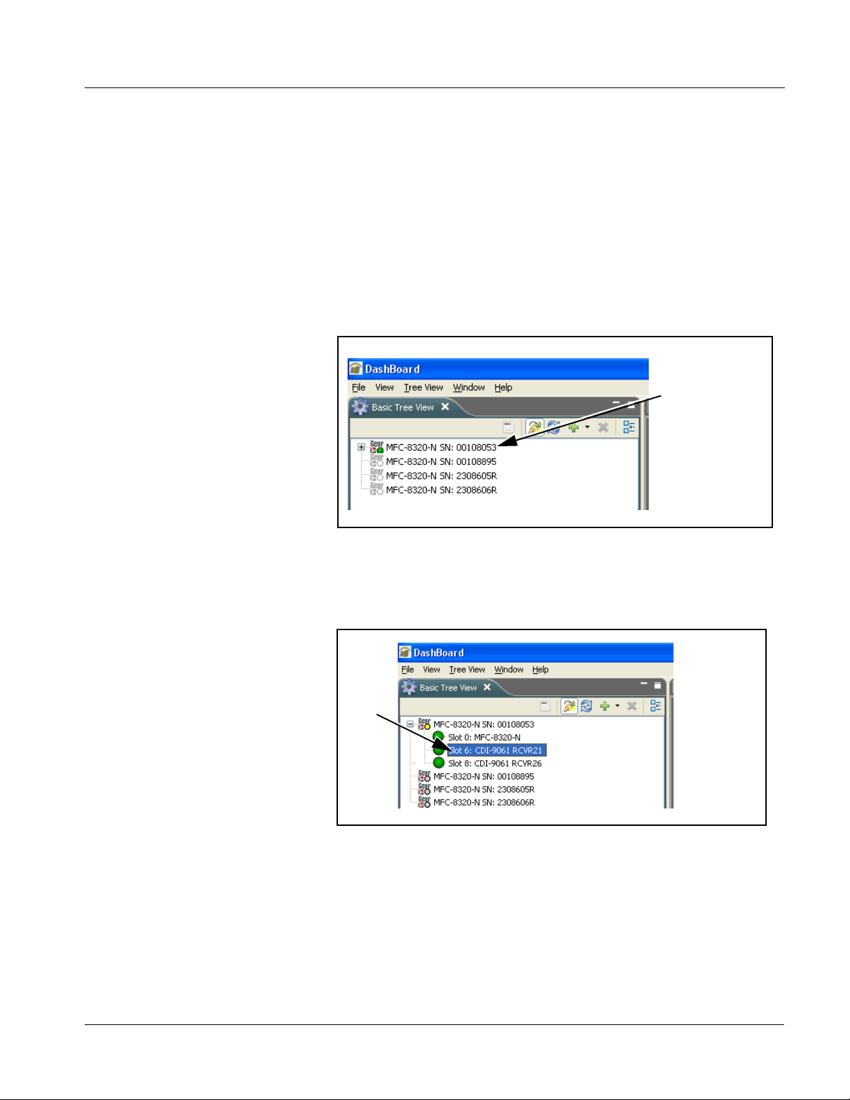
Operating Instructions Accessing the 9061 Card via Remote Control
Accessing the 9061 Card via Remote Control
Access the 9061 card using DashBoard™ or Cobalt® Remote Control Panel
as described below.
Accessing the 9061 Card Using DashBoard™
1. On the computer connected to the frame LAN, open DashBoard™.
2. As shown belo w (in the left side Basic View Tree) locat e the Network
Controller Card asso ci ated wi th th e fra me co ntain ing th e 9061 c ard t o be
accessed (in this example, “MFC-8320-N SN: 00108053”).
DB_ACCESS1.PNG
3. As shown below, expand the tree to access the cards within the frame.
Click on the card to be accessed (in this example,
“Slot 6: CDI-9061 RCVR21”).
.
DB_ACCESS2A.PNG
As shown on the next page, when the card is accessed in DashBoard™
its function submenu scree n showing ta bs for eac h functi on is disp layed.
(The particular submenu screen displayed is the previously displayed
screen from the last time the card was accessed by DashBoard™).
9061-OM (V4.9) 9061 PRODUCT MANUAL 3-5
Page 50

3 Accessing the 9061 Card via Remote Control
Card Access/Navigation
Tree Pane
Card Info
Pane
Card Function Submenu
and Controls Pane
Accessing the 9061 Card Using a Cobalt® Remote Control Panel
Press the Select Device key and select a c ard as shown in the example bel ow.
3366_3392.JPG
This display shows the list
order number of the device that
is ready for selection
This display shows the devices assigned to the Control Panel.
• Rotate any knob to select from the list of devices. The device selected using a knob
is displayed with a reversed background (in this example,
“1 9061 - Receiver 21 Input Processing”).
• Directly enter a device by entering its list number using the numeric keypad, and
then pressing Enter or pressing in any knob).
9061_DB_ACCESS_V4.PNG
3-6 9061 PRODUCT MANUAL 9061-OM (V4.9)
Page 51
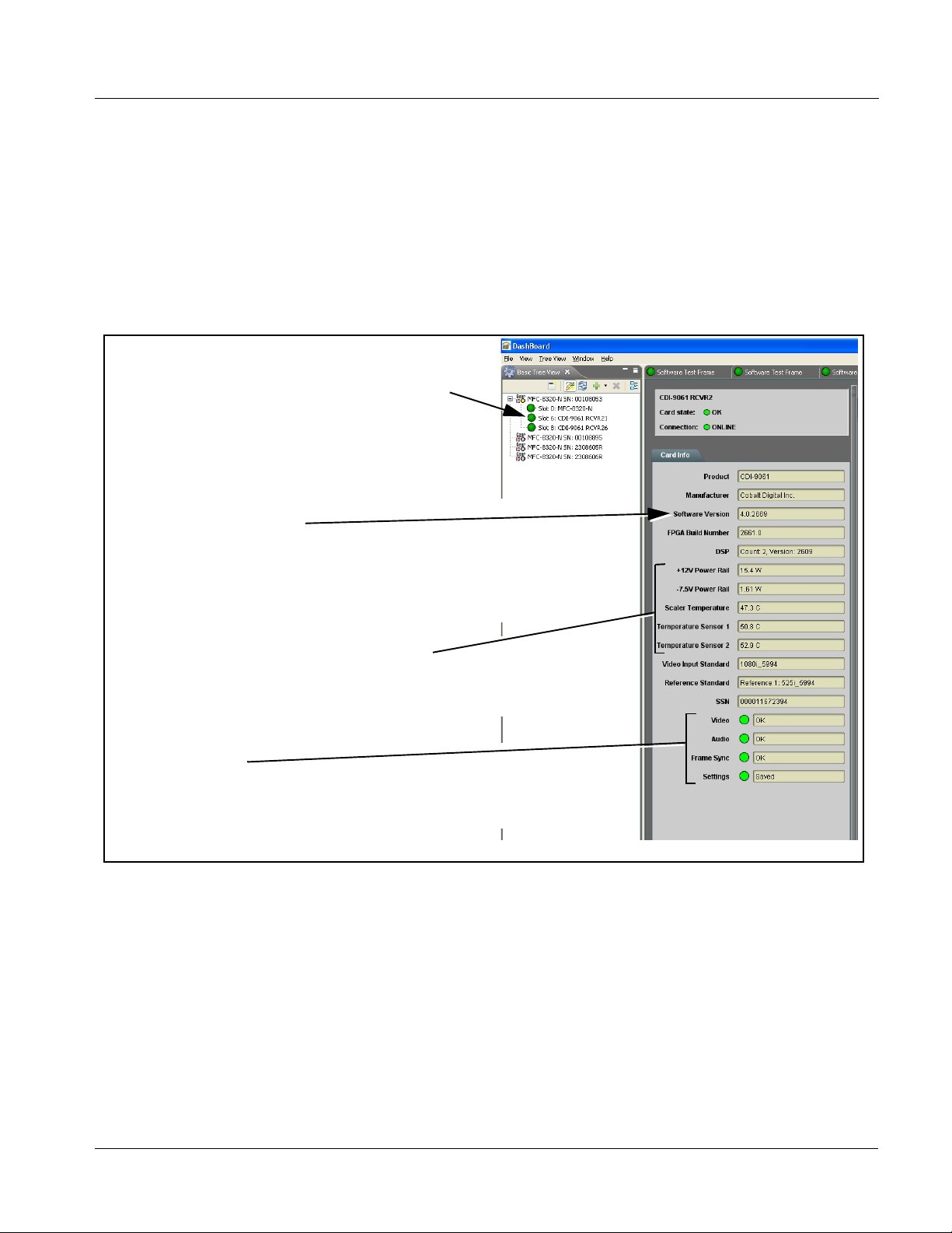
Operating Instructions Checking 9061 Card Information
Checking 9061 Card Information
The operating st atus and s oftwar e ver sion the 9 061 car d can be chec ked us ing
DashBoard™ or the card edge control user interface. Figure 3-4 shows and
describes the 9061 card i nformati on screen usi ng DashBoard™ a nd acces sing
card information using the card edg e control user interfac e.
Note: Proper operating status in DashBoard™ is denoted by green icons for the sta-
tus indicators shown in Figure 3-4. Yellow or red icons respectively indicate
an alert or failure condition. Refer to Troubleshooting (p. 3-64) for corrective
action.
The Tree View shows the cards seen by DashBoard™.
In this example, Network Controller Card is hosting a
9061 card in slot 6.
Software Version Number
Refer to these numbers to check that documentation (such as
this manual) matches the card’s Software Release Number
and Software Build Number. Use these numbers also when
communicating to Cobalt
Power Consumption and Temperature Displays
This display shows the power consumed by the 9061
for both the +12V and -7.5V rails, as well as key device
temperatures.
Status Displays
These displays show the status the signal being received by
the 9061. Green Settings icon shows that any changes made
on DashBoard™ are sucessfully saved on the card’s memory.
®
regarding this card.
Figure 3-4 9061 Card Info Utility
9061-OM (V4.9) 9061 PRODUCT MANUAL 3-7
Page 52
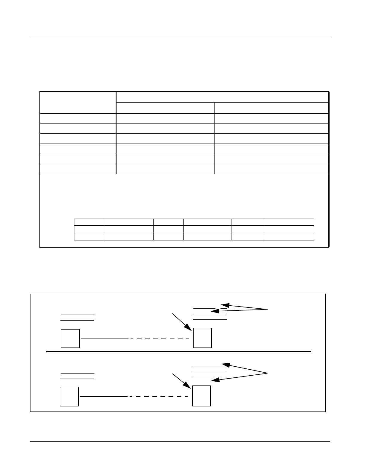
3 Ancillary Data Line Number Locations and Ranges
Ancillary Data Line Number Locations and Ranges
Table 3-1 lists typical default output video VANC line number locations for
various ancillary data items that may be passed or handled by the card.
Table 3-1 Typical Ancillary Data Line Number Locations/Ranges
Default Line No. / Range
Item
SD HD
AFD 12 (Note 2) 9 (Note 2)
ATC_VITC 13 (Note 2) 9/8 (Note 2)
ATC_LTC — 10 (Note 2)
®
Dolby
Metadata 13 (Note 2) 13 (Note 2)
SDI VITC Waveform 14/16 (Note 2) —
Closed Captioning 21 (locked) 10 (Note 2)
Notes:
1. The card does not check for conflicts on a given line number. Make certain the selected line is available
and carrying no other data.
2. While range indicated b y d rop -dow n li st o n G UI m ay al lo w a particular range of choices, the act ual ran ge
is automatically cl amped (limi ted) to c ert ain rang es to preven t inadv ertent con fli ct with a ctive pictu re ar ea
depending on video format. Limiting ranges for various output formats are as follows:
Format Line No. Limiting Format Line No. Limiting Format Line No. Limiting
525i 12-19 720p 9-25 1080p 9-41
625i 9-22 1080i 9-20
Because line number allocation is not standardized for all ancillary items,
consideration should be given to all items when performing set-ups. Figure
3-5 shows an example of improper and corrected VANC allocation within an
HD-SDI stream.
ATC_VITC = 9/8
CC = 10
Dolby Meta data = 13
Card 1
ATC_VITC = 9/ 8
CC = 10
Dolby Metadata = 13
Card 1
AFD Insertion
attempted usin g
VANC line 9
(default)
AFD Insertion
corrected to us e
VANC line 18
ATC_VITC = 9/8
AFD = 9
CC = 10
Dolby Meta data = 13
Card n
ATC_VITC = 9/8
CC = 10
Dolby Metadata = 13
AFD = 18
Card n
Conflict between
ATC_VITC and AFD both
on VANC line 9
Conflict between
ATC_VITC on line 9/8 and
AFD (now on line 18)
resolved
Figure 3-5 Example VANC Line Number Allocation Conflict and Resolution
3-8 9061 PRODUCT MANUAL 9061-OM (V4.9)
Page 53

Operating Instructions 9061 Function Submenu List and Descriptions
9061 Function Submenu List and Descriptions
T able 3 -2 indiv iduall y list s and desc ribes ea ch 9061 fu nctio n submenu (“tab”)
and its related list selections, co ntrols, and parameters . Where helpful,
examples showing usage of a function are also provided. Table 3-2 is
primarily based upon using DashBoard™ to access each function and its
corresponding submenus and parameters.
Note: All numeric (scalar) parameters displayed on DashBoard™ can be changed
using the slider controls, arrows, or by numeric keypad entry in the corresponding numeric field. (When using numeric keypad entry, add a return after
the entry to commit the entry.)
On DashBoard™ itself and in Table 3-2, the function submenu items are
organized using tabs as shown below.
The table below provides a quick-reference to the page numbers where each
function submenu item can be found.
Function Submenu Item Page Function Submenu Item Page
Video Signal Controls
Audio Input Controls
Video Proc
Scaler
AFD
Overlays
Framesync
Embedded Audio Group 1/2
Embedded Audio Group 3/4
AES Audio Out Pairs 1-4
3-10
3-11
3-13
3-14
3-19
3-23
3-27
3-32
3-36
3-38
AES Audio Out Pairs 5-8
Dolby Metadata
Closed Captioning
Timecode
Audio Mixing
Tone Generator
Licensable Features
Presets
Advanced Setup
3-42
3-43
3-44
3-46
3-50
3-55
3-55
3-56
3-58
9061-OM (V4.9) 9061 PRODUCT MANUAL 3-9
Page 54
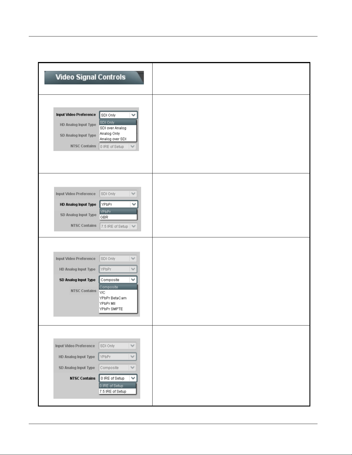
3 9061 Function Submenu List and Descriptions
Table 3-2 9061 Function Submenu List
Sets the 9061 video signal input type and preference
and priority.
Video Signal Controls
• Input Video Preference Sets the input video preference and priority for SDI and analog video
• HD Analog Input Type When receiving analog video input, sets the 9061 HD input video type to
• SD Analog Input Type When receiving analog video input, sets the 9061 SD input video type to
inputs as follows:
• SDI Only: Sets the video input to accept only SDI input. Blocks all
analog video inputs.
• SDI over Analog: Sets the video input to accept SDI over
composite/component analog video inputs. Blocks analog video
inputs when valid signal is received by SDI input.
• Analog Only: Sets the video input to accept only composite and/or
component analog video inputs. Blocks SDI input.
• Analog over SDI: Sets the video input to accept composite/
component analog over SDI video inputs. Blocks SDI input when
valid signal is received by composite and/or component analog
video inputs.
accept received input signal from choices shown.
Note: Input type must be appropriately set for the 9061 to correctly
process the received input.
accept received input signal from choices shown.
Note: Input format must be appropriately set for the 9061 to correctly
lock to the input.
• NTSC Contains This setting tells the 9061 how much setup (pedestal) needs to
be removed from an NTSC-formatted input.
• 0 IRE of Setup: No setup removed.
• 7.5 IRE of Setup: Removes 7.5 IRE of setup. This is typically
preferred when analog signals containing 7.5 IRE pedestal are
converted to SDI.
3-10 9061 PRODUCT MANUAL 9061-OM (V4.9)
Page 55
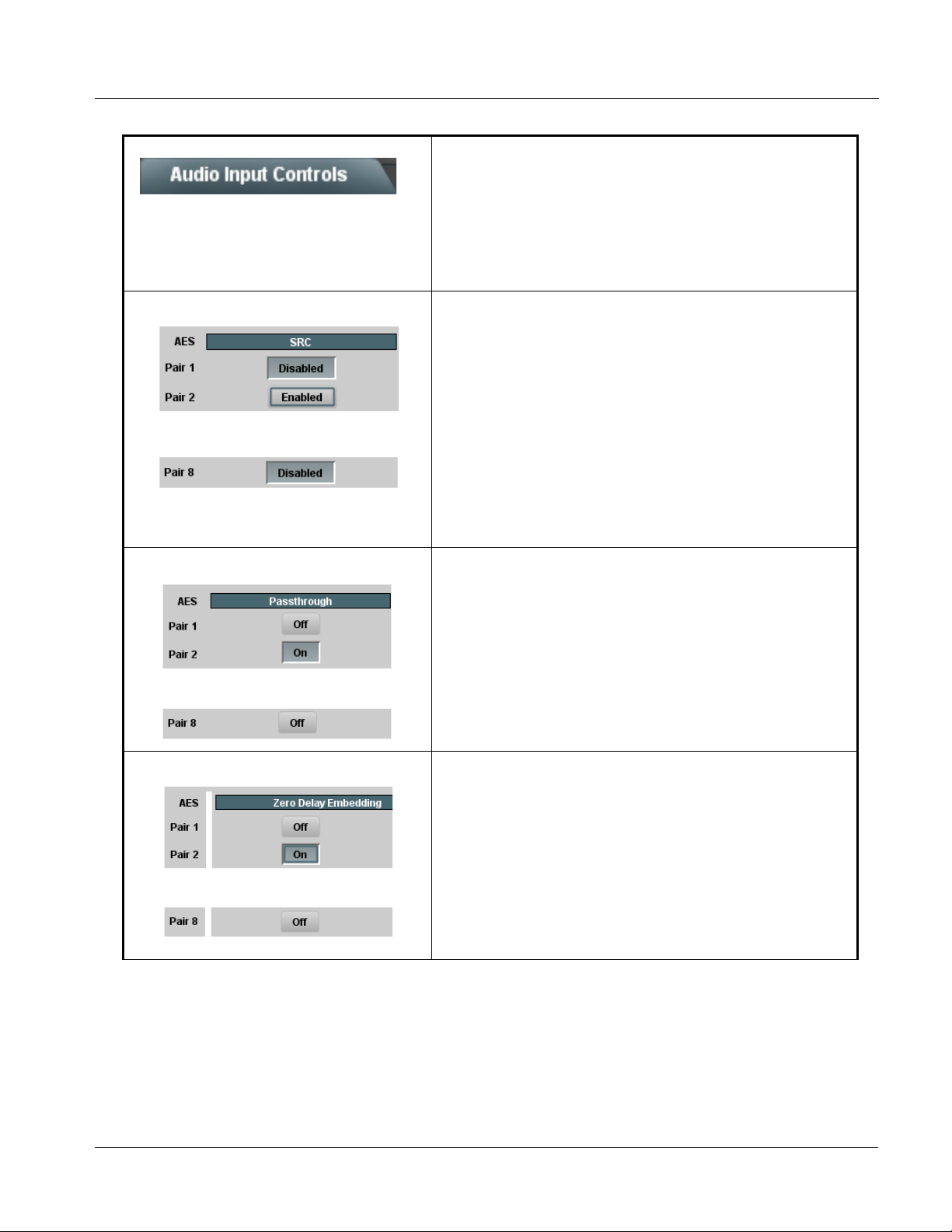
Operating Instructions 9061 Function Submenu List and Descriptions
Table 3-2 9061 Function Submenu List — continued
Controls the AES Audio Input features for the eight AES
pairs, and displays signal status for the AES pairs and
Audio Input Controls
the 16 embedded audio channels. Also provides global
unity routing/par ameter control resets.
Note: Also refer to AES Audio Input Advanced Features (p.
1-19) in Chapter 1,“Introduction” for detailed
information regarding these func ti ons .
• AES SRC Individual SRC Disable control for each AES pair (1 thru 8) disables or
•
•
•
• AES Passthrough Individual AES Passthrough On/Off control for each AES pair (1 thru 8)
•
•
•
enables Sample Rate Conversion (SRC) bypass as follows:
• Disabled: In this mode, AES SRC for the corresponding AES pair is
bypassed. SRC is set to Disabled by default. This mode is
preferred where the AES rate matches the input video rate. This
mode is necessary when embedding non-PCM AES audio such a
®
E or Dolby Digital™ audio streams.
Dolby
Note: In this mode AES rate must match the input video rate or
audio dropouts will occur.
Note: AES audio must be nominally 48 kHz.
• Enabled: In this mode, AES SRC for the corresponding AES input
pair is enabled. SRC enabled allows the 9061 to interface with
asynchronous AES sources (sources in which the AES timing does
not match the video reference timing). SRC can be used to
compensate for minor clock rate differences in the AES stream and
the input video stream.
disables or enables Passthrough as follows:
• Off: Disables AES passthrough for the selected AES input pair.
Passthrough is set to Off by default.
• On: Passthrough is turned on, with the corresponding AES output
pair to act as a bit-for-bit copy with zero delay of the corresponding
AES input pair.
Note: AES Passthrough set to On overrides normal audio routing.
Gain and polarity control is not available when AES
passthrough is enabled.
• Zero Delay Embedding Individual AES Zero-Delay Embedding On/Off control for each AES pair
•
•
•
9061-OM (V4.9) 9061 PRODUCT MANUAL 3-11
(1 thru 8) disables or enables Zero-Delay Embedding as follows:
• Off: Disables Zero-Delay Embedding for the selected AES input
pair. Zero-delay embedding is set to Off by default.
• On: The selected pair directly embeds into its corresponding group
(AES Pair 1 embeds into embedded channels 1 and 2; AES pair 2
embeds into embedded channels 3 and 4, and so on) with the
normal frame sync audio delay being bypassed.
Note: Zero Delay Embedding overrides the standard audio routing
system. For example, if AES Pair 1 is selected, then the
controls to route into embedded channels 1 and 2 will not
apply. Gain and polarity control is not available when
zero-delay embedding is enabled.
Page 56
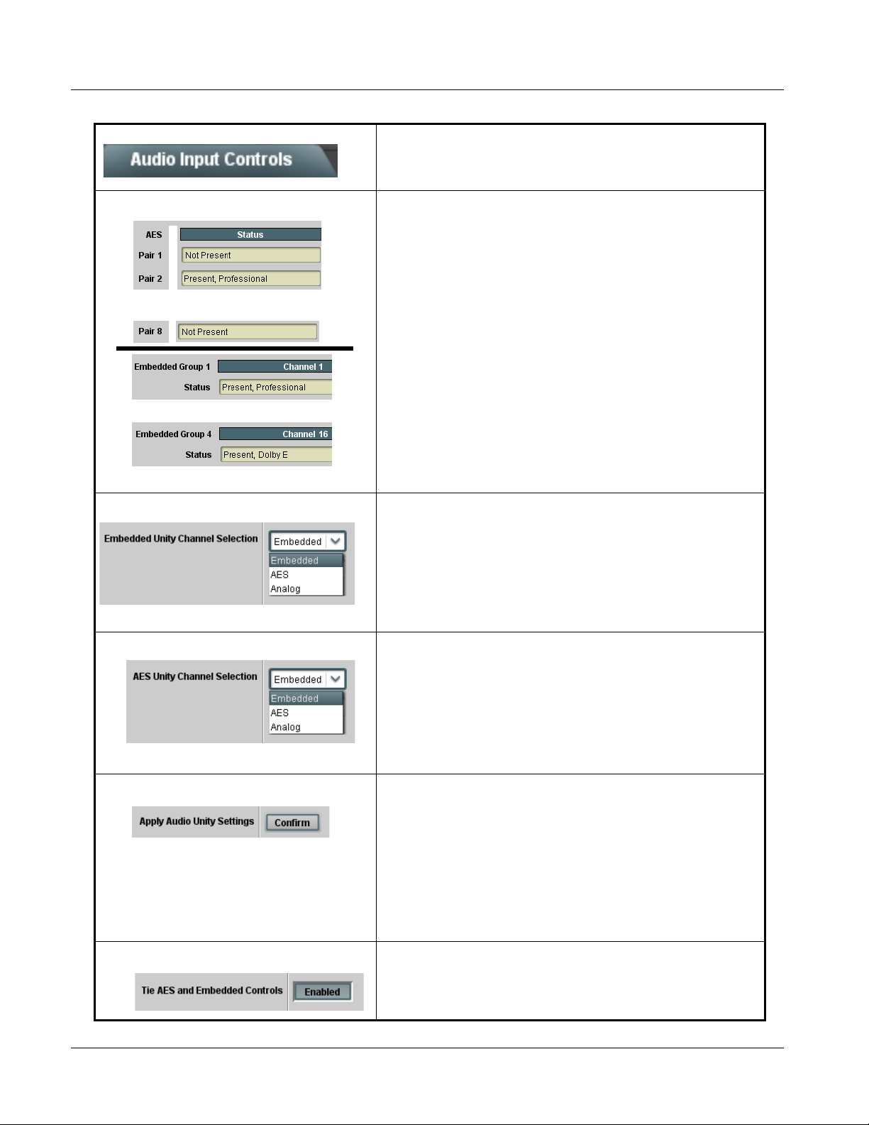
3 9061 Function Submenu List and Descriptions
Table 3-2 9061 Function Submenu List — continued
(continued)
• Status Displays Individual signal status displays for AES pairs 1-8, and embedded audio
•
•
•
•
•
•
• Embedded Unity Channel Selection Selects unity reset of Embedded Audio Group 1/2 and 3/4 controls and
channels 1-16 as follows:
• Not Present: Indicates AES pair or embedded channel does not
contain recognized audio PCM data.
Note: Channel displaying Not Present may still carry usable audio
data with Not Present being displayed due to invalid
headers.
• Present, Professional: Indicates AES pair or embedded channel
contains recognized AES audio PCM data.
• Present, Consumer: Indicates AES pair or embedded channel
contains audio PCM data other than AES (for example, S/PDIF).
• Present, Dolby E: Indicates AES pair or embedded channel
contains Dolby
• Present, Dolby Digital: Indicates AES pair or embedded channel
contains Dolby
Note:Dolby status displays shown to the left only occur for valid
re-establishes default 1-to-1 routing as follows:
• Embedded: Routes Embedded Ch 1 thru Ch 16 as sources to
destination channels Embedded Ch 1 thru Embedded Ch 16.
• AES: Routes AES Ch 1 thru Ch 16 as sources to destination
channels Embedded Ch 1 thru Embedded Ch 16.
• Analog: Routes Analog Ch 1 thru Ch 8 as sources to destination
channels Embedded Ch 1 thru Embedded Ch 8. Sets Embedded
Ch 9 thru Ch 16 to Silence.
®
E encoded data.
®
Digital encoded data.
®
signals meeting SMPTE 337M standard.
Dolby
The 9061 card does not perform Dolby® processing on the
signal. Although the 9061 controls will appear to be usable
for this signal tag, the signal is passed with 1-to-1 routing
and all related gain and polarity controls set to unity .
• AES Unity Channel Selection Selects unity reset of AES Outputs Pairs 1-4 and 5-8 controls and
• Apply Audio Channel Selection Applies embedded and AES unity channel selection (as set in the above
• Tie AES and Embedded Controls When set to Enabled, gangs Gain, Phase, and Mute controls for
re-establishes default 1-to-1 routing as follows:
• Embedded: Routes Embedded Ch 1 thru Ch 16 as sources to
destination channels AES Ch 1 thru AES Ch 16.
• AES: Routes AES Ch 1 thru Ch 16 as sources to destination
channels AES Ch 1 thru AES Ch 16.
• Analog: Routes Analog Ch 1 thru Ch 8 as sources to destination
channels AES Ch 1 thru AES Ch 8. Sets AES Ch 9 thru Ch 16 to
Silence.
drop-down lists). To apply the selections, click the Confirm button. When
Confirm is clicked, a Confirm? pop-up appears, requesting confirmation.
• Click Yes to proceed with the unity reset.
• Click No to reject unity reset.
For any selection following confirm, the destination channel controls are
default reset as follows:
• Gain is to unity
• Phase control is set to Normal
• Channel is set to Unmuted
same-numbered Embedded and AES channels. Ganging is bilateral, with
embedded channel control settings affecting corresponding AES channel
controls, and vice-versa.
3-12 9061 PRODUCT MANUAL 9061-OM (V4.9)
Page 57
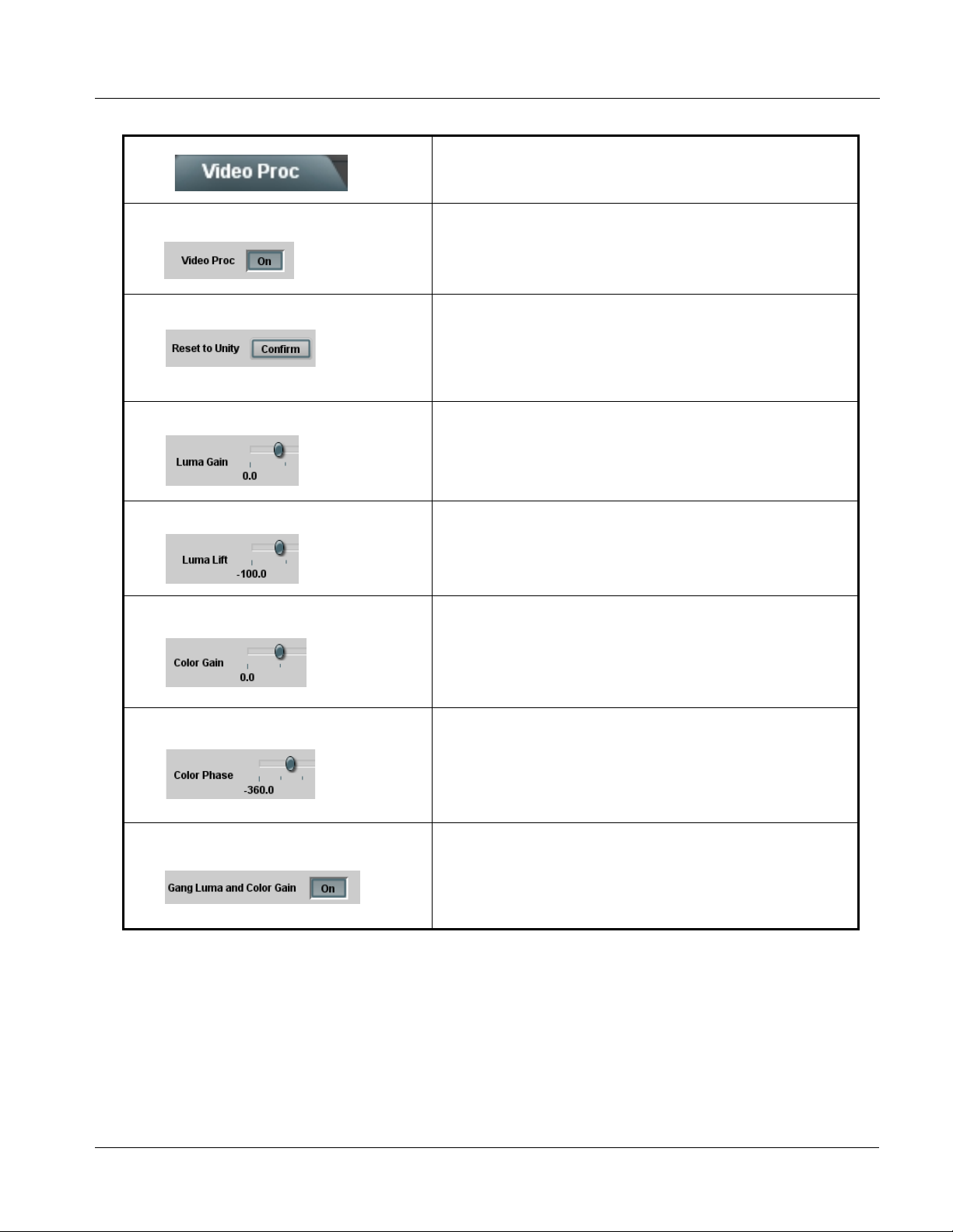
Operating Instructions 9061 Function Submenu List and Descriptions
Table 3-2 9061 Function Submenu List — continued
Provides the following Video Proc parametric controls.
• Video Proc Video Proc (On/Off) provides master on/off control of all Video Proc
• Reset to Unity Reset to Unity provides unity reset control of all Video Proc functions.
• Luma Gain Adjusts gain percentage applied to Luma (Y channel).
functions.
• When set to Off, Video Proc is bypassed.
• When set to On, currently displayed parameter settings take effect.
When Confirm is clicked, a Confirm? pop-up appears, requesting
confirmation.
• Click Yes to proceed with the unity reset.
• Click No to reject unity reset.
(0% to 200% range in 0.1% steps; unity = 100%)
Video Proc
• Luma Lift Adjusts lift applied to Luma (Y-channel).
(-100% to 100% range in 0.1% steps; null = 0.0%)
• Color Gain Adjusts gain percentage (saturation)
applied to Chroma (C-channel).
(0% to 200% range in 0.1% steps; unity = 100%)
• Color Phase Adjusts phase angle applied to Chroma.
(-360° to 360° range in 0.1° steps; null = 0°)
• Gang Luma and Color Gain When set to On, changing either the Luma Gain or Color Gain controls
9061-OM (V4.9) 9061 PRODUCT MANUAL 3-13
increases or decreases both the Luma and Chroma levels by equal
amounts.
Page 58

3 9061 Function Submenu List and Descriptions
Table 3-2 9061 Function Submenu List — continued
Provides video format up/down/cross-conversions and
aspect ratio controls.
Note: Scaling and/or format conversion removes Dolby
and needs to be preserved, use the Dolby Metadata function tab to preserve and re-apply the metadata on the output
SDI. Refer to Dolby Metad ata function on page 3-43 for more information.
• Scaler enable Enables or bypasses Scaler function as follows:
®
metadata and A TC packets (if present). If Dolby® metadata is present
• Enabled: Provides Scaler functions for the received video input.
• Bypassed: Received video input bypasses the Scaler functions.
Scaler
• Current Input Format Displays the input format of the video currently being received by the 9061
(for example, 1080p at 29.97 Hz frame rate as shown here).
Note: Rates displayed for progressive formats are frame rates; rates
displayed for interlaced formats are field rates.
Current Input Format
• Current Output Format Displays the currently selected output format of the video currently being
processed by the 9061 (for example, 1080p at 29.97 Hz frame rate as
shown here). The output format displayed is the output present on the
card’s SDI OUT BNC connectors.
Current Output Format
Note: Output format shown in this display tracks with selection made in
display only tracks with changes applicable to the currently
received input format (for example, when currently receiving HD
video, changes made in the drop-down list have no
effect on the Output Format display). Output forma t al so tracks
with any applicable Scaler functions that affect output format.
Note: Rates displayed for progressive formats are frame rates; rates
displayed for interlaced formats are field rates.
or drop-down lists. Output Format
Note: S D: controls described below affect SD inputs; HD: controls described below affect HD inputs.
• SD: Convert To When SD video input is received by the 9061, provides output format
conversions, or re-aspecting to SD when SD is the detected input format
as described below.
• SD (Same as input): Output follows currently received video input
format, with Current Input Format and Current Output Format
displays showing same selection.
• 720p: Output is converted to 720p
• 720 film: Output is converted to corresponding 720p film frame rate
• 1080i: Output is converted to 1080i
• 1080p: Output is converted to 1080p
• 1080 film: Output is converted to corresponding 1080i film
frame rate
• Output Follows Reference In: Output tracks with format set in
Reference Video Input
Note: Output Follows Reference In selection automatically sets
the output format to that of the received reference signal
input (this signal is distributed to the 9061 and other cards
via a frame bus). In addition to extracting a frame sync and
rate, this function determines the type of black burst (i.e.,
black burst or tri-level) and sets the output format to match.
SD: Convert To
3-14 9061 PRODUCT MANUAL 9061-OM (V4.9)
Page 59

Operating Instructions 9061 Function Submenu List and Descriptions
Table 3-2 9061 Function Submenu List — continued
Scaler Video Format Conversions
(continued)
Scaler Video Format Conversions
Scaler Video Format Conversions
The Scaler HD: Convert to: a nd SD: Conver t to: drop-down lists (as shown and de scribed in
the following pages) allows selection of up/down/cross-conversions (or no conversion) for
various input forma ts. The table below lists the conversion choic es available for various input
formats and frame rates provided by the Scaler Convert to: function. Also shown are the
resulting frame rates for the converted outputs.
Input
Format
525i 59.94 525i 59.94 720p 59.94 720p 29.97 720p 23.98
SD
(NTSC/
PAL)
720p
720p
half-rate
720p
(film rates)
(4)
1080i 1080p
1080p
(film rates)
1080i 59.94 1080p 29.97 1080p 23.98
(4)
1080PsF
(film rates)
1080PsF 23.98
(4)
625i 50 625i 50 720p 50 720p 25 X 1080i 50 1080p 25 X X
720p 60 X 720p 60 720p 30 720p 24
720p 59.94 525i 59.94 720p 59.94 720p 29.97 720p 23.98
1080i 60 1080p 30 1080p 24
(4)
1080i 59.94 1080p 29.97 1080p 23.98
(4)
(4)
1080PsF 24
(4)
1080PsF 23.98
(4)
(4)
720p 50 625i 50 720p 50 720p 25 X 1080i 50 1080p 25 X X
720p 30 X 720p 60 720p 30 720p 24
720p 29.97 525i 59.94 720p 59.94 720p 29.97 720p 23.98
1080i 60 1080p 30 1080p 24
(5)
1080i 59.94 1080p 29.97 1080p 23.98
(5)
(5)
1080PsF 24
(5)
1080PsF 23.98
(5)
(5)
720p 25 625i 50 720p 50 720p 25 X 1080i 50 1080p 25 X X
720p 24 X 720p 60 720p 30 720p 24 1080i 60 1080p 30 1080p 24 1080PsF 24
720p 23.98 525i 59.94 720p 59.94 720p 29.97 720p 23.98 1080i 59.94 1080p 29.97 1080p 23.98 1080PsF 23.98
1080i 60 X 720p 60 720p 30 720p 24
1080i 59.94 525i 59.94 720p 59.94 720p 29.97 720p 23.98
1080i 60 1080p 30 1080p 24
(4)
1080i 59.94 1080p 29.97 1080p 23.98
(4)
(4)
1080PsF 24
(4)
1080PsF 23.98
(4)
(4)
1080i 50 625i 50 720p 50 720p 25 X 1080i 50 1080p 25 X X
1080p 30 X 720p 60 720p 30 720p 24
1080p 29.97 525i 59.94 720p 59.94 720p 29.97 720p 23.98
1080i 60 1080p 30 1080p 24
(5)
1080i 59.94 1080p 29.97 1080p 23.98
(5)
(5)
1080PsF 24
(5)
1080PsF 23.98
(5)
(5)
1080p 25 625i 50 720p 50 720p 25 X 1080i 50 1080p 25 X X
1080p 24 X 720p 60 720p 30 720p 24 1080i 60 1080p 30 1080p 24 1080PsF 24
1080p 23.98 525i 59.94 720p 59.94 720p 29.97 720p 23.98 1080i 59.94 1080p 29.97 1080p 23.98 1080PsF 23.98
1080PsF 24 X 720p 60 720p 30 720p 24 1080i 60 1080p 30 1080p 24 1080PsF 24
1080PsF 23.98 525i 59.94 720p 59.94 720p 29.97 720p 23.98 1080i 59.94 1080p 29.97 1080p 23.98 1080PsF 23.98
Notes:1. The drop-down list choice of “Same as Input” is used when no conversion is desired. For clarity, it is not redundantly
listed here.
2. “X” denotes conversions not available or invalid conversions.
3. Interlaced formats rates listed are field rates. Progressive format rates listed are frame rates.
4. If the original material does not have a proper 3-2 cadence suitable for conversion to film rates, the conversion
reverts to standard de-interlacing. While this video can be converted to film rates, the resulting image motion will
lack smoothness. Therefore, make certain interlaced video is appropriately constructed for 3-2 reverse pulldown
when converting video to film rates. (See 3-2 Pulldown Conversion and Considerations (p. 1-12) for more
information.)
5. Formats using a 30/29.97 Hz progressive frame rate can be converted to a 24/23.98 Hz progressive frame rate,
however some image motion irregularity will appear in the converted output.
9061-OM (V4.9) 9061 PRODUCT MANUAL 3-15
Page 60

3 9061 Function Submenu List and Descriptions
Table 3-2 9061 Function Submenu List — continued
(continued)
• SD: Output Half-rate 720p When drop-down list is set to 720p, converts output to
• SD: Output PsF When enabled (and with the output video is set to 1080 film), converts the
• SD: Aspect Ratio Conversion Selects between the standard preset Aspect Ratio Conversions (ARC)
720p half-rate.
Yes/No control functions as follows:
• No: Do not apply half-rate; leave output at standard frame rate
• Yes: Output set at half- rate
Note: Half-rate outputs are available for the 720p frame rates listed under
“720p” in the “Scaler Video Format Conversions” table on the
previous page.
output to1080PsF (segmented frame progressive).
shown here, as well as User Defined and Follow AFD Settings.
• User Defined settings allow custom user-defined H and V aspect
ratio control.
• Follow AFD Settings sets the output aspect ratio to track with AFD
settings performed in AFD (p. 3-19).
Note: This function is intended for aspect ratio adjustment of a particular
signal without AFD considerations.
• If ARC is being used on a case-by-case basis for a particular
signal, it is easier to use the Scaler ARC tools described here.
• If AFD is to be used to set and apply a standard AFD code label
for ARC, use Follow AFD Settings. Do not perform ARC here;
instead, perform ARC as described in the AFD function
description on page 3-19.
• SD: User-defined aspect ratio (Horizon tal) and (Vertical) controls adjust horizontal and vertical zoom
• SD: Top line suppression Selects the number of lines suppressed at the beginning of video. In this
• SD: Side pixel suppression Selects the number of pixels at the left and right horizontal margins within
percentage. Settings less than (<) 100% provide zoom-out; settings
greater than (>) 100% provide zoom-in.
(50% to 200% range in 0.1% steps; null = 100.0)
manner, the image is scaled proportionally to replace the top few lines
suppressed using this control. When upconverting from SD to HD, using
this control can hide unwanted closed caption or timecode data.
(Range is 0 thru 10 lines.)
the SAV and EAV portions of each line.
(Range is 0 thru 20 pixels.)
3-16 9061 PRODUCT MANUAL 9061-OM (V4.9)
Page 61

Operating Instructions 9061 Function Submenu List and Descriptions
Table 3-2 9061 Function Submenu List — continued
(continued)
• HD: Convert To When HD video input is received by the 9061, provides output format
• HD: Output Half-rate 720p When drop-down list is set to 720p, converts output to 720p
conversions listed below.
• HD (Same as input): Output follows currently received video input
format, with Current Input Format and Current Output Format
displays showing same selection.
• SD (NTSC or PA L): Output is converted to 525i at 59.94 Hz frame
rate or 625i at 50 Hz rate, as applicable.
• 720p: Output is converted to 720p
• 720 film: Output is converted to corresponding 720p film frame rate
• 1080i: Output is converted to 1080i
• 1080p: Output is converted to 1080p
• 1080 film: Output is converted to corresponding 1080i film
frame rate
• Output Follows Reference In: Output tracks with format set in
Reference Video Input
Note: Output Follows Reference In selection automatically sets
the output format to that of the received reference signal input
(this signal is distributed to the 9061 and other cards via a
frame bus). In addition to extracting a frame sync and rate,
this function determines the type of black burst (i.e., black
HD: Convert To
half-rate.
burst or tri-level) and sets the output format to match.
Yes/No control functions as follows:
• No: Do not apply half-rate; leave output at standard frame rate
• Yes: Output set at half-rate
Note: Half-rate outputs are available for the 720p frame rates listed under
“720p” in the “Scaler Video Format Conversions” table on page
3-15.
• HD: Output PsF When enabled (and with the output video is set to 1080 film) converts
• HD: Aspect Ratio Conversion Selects between the standard preset Aspect Ratio Conversions (ARC)
output to 1080PsF (segmented frame progressive).
shown here, as well as User Defined and Follow AFD Settings.
• User Defined settings allow custom user-defined H and V aspect
ratio control.
• Follow AFD Settings sets the output aspect ratio to track with AFD
settings performed in AFD (p. 3-19).
Note: This function is intended for aspect ratio adjustment of a particular
signal without AFD considerations.
• If ARC is being used on a case-by-case basis for a particular
signal, it is easier to use the Scaler ARC tools described here.
• If AFD is to be used to set and apply a standard AFD code label
for ARC, use Follow AFD Settings. Do not perform ARC here;
instead, perform ARC as described in the AFD function
description on page 3-19.
9061-OM (V4.9) 9061 PRODUCT MANUAL 3-17
Page 62

3 9061 Function Submenu List and Descriptions
Table 3-2 9061 Function Submenu List — continued
(continued)
• HD: User-defined aspect ratio (Horizontal) and (Vertical) controls adjust horizontal and vertical zoom
• HD: Top line suppression Selects the number of lines suppressed at the beginning of video. In this
• HD:Side pixel suppression Selects the number of pixels at the left and right horizontal margins within
• Detail Enhancement Controls Sharpness Level, Threshold, and Noise Reduction controls (individually
percentage. Settings less than (<) 100% provide zoom-out; settings
greater than (>) 100% provide zoom-in.
(50% to 200% range in 0.1% steps; null = 100.0)
manner, the image is scaled proportionally to replace the top few lines
suppressed using this control. When upconverting from SD to HD, using
this control can hide unwanted closed caption or timecode data.
(Range is 0 thru 10 lines.)
the SAV and EAV portions of each line.
(Range is 0 thru 20 pixels.)
described below) which can be used to tailor output video sharpness per
program material and aesthetic preferences.
Note: Detail Enhancement Controls apply to both SD and HD
conversions.
• S h arpness Level Control Adjusts the aggressiveness of sharpening applied to MPEG video.
• S h arpness Threshold Control Adjusts the point at which sharpening rules become active. Data below
• Noise Reduction Control Adjusts the amount of statistical low-pass filtering applied to the data.
Optimum setting results in overall perception of increased sharpness,
while avoiding pattern noise artifacts.
(Range is 0 thru 255)
the threshold setting is passed unaffected.
Higher settings allow for a more subtle sharpness enhancement
(especially with content showing motion). Lower settings allow more
content in general to be acted upon by the enhancement process.
(Range is 0 thru 255)
Using this control, regular pattern noise artifacts from the sharpening
process can be reduced, resulting in subjectively smoother raster
backgrounds and detail boundaries.
(Range is 0 thru 63)
3-18 9061 PRODUCT MANUAL 9061-OM (V4.9)
Page 63

Operating Instructions 9061 Function Submenu List and Descriptions
Table 3-2 9061 Function Submenu List — continued
Allows assignment of AFD (Active Format Description)
codes to the SDI output video, and allows unique ARC
AFD
Without AFD
settings to be applied for each AFD code.
When an appropriate AFD code is received by this card,
this function can be used to apply the AFD-directed
re-aspecting, resulting in a properly scaled and cropped
image area.
NTSC-Coded
(4:3) 1080i
Video Signal
NTSC-Coded
image on 16:9
display shows
letterbox cropping
With AFD
NTSC-Coded
(4:3) 1080i
Video Signal
with 1010
AFD Code
NTSC-Coded
image on 16:9
display shows
letterbox cropping
9061 with 1010
AFD Code
Received and
Applied
Up-Conversion
to 16:9
Uncorrected
up-conversion
results in “postage
stamp” effect with
both letterbox and
sidebars visible on
16:9 display
Up-Conversion
to 16:9
AFD Corrected
up-conversion
results in intended
image area
properly visible on
16:9 display
1080i Video Signal
with 16:9
uncorrected signal
1080i Video Signal
with 16:9
corrected signal
9061-OM (V4.9) 9061 PRODUCT MANUAL 3-19
Page 64

3 9061 Function Submenu List and Descriptions
Table 3-2 9061 Function Submenu List — continued
(continued)
• Incoming AFD Displays incoming AFD setting as follows:
• If AFD code is present, one of the 1 1, four-bit AFD codes is displayed (as
shown in the example to the left). Also displayed is the VANC line
number of the incoming AFD code.
• I f no AFD setting is present in the video signal, No AFD Present is
displayed.
AFD
• 16:9 Controls Individual user (custom) H Zoom, V Zoom, and AFD Output Code tools
for the following 12 AFD codes/formats suited for 16:9 sources:
AFD Code
•
•
•
1: AFD codes numbering and definitions conform to SMPTE 2016-1-2007.
2: Image Prot ecte d impl ies pictu re cont ent that must not be cropped by
(1)
Description AFD Code
– No code present 1001 4:3 (center)
0000 Undefined 1010
0010 Full frame 1011 14:9 (center)
0011 4:3 (center) 1101
0100
1000 Full frame 1111
conversion processes or display devices. Alternate center formats may
have protected center areas, with areas outside of the protected area not
containing mandatory content. Refer to SMPTE 2016-1-2007 for more
information if needed.
Box > 16:9
(center)
1110
(1)
4:3 (with alternate
16:9 (with alternate
14:9 center)
16:9 (with alternate
4:3 center)
Description
16:9 (image
protected)
14:9 center )
(2)
(2)
(2)
• 4:3 Controls Individual user (custom) H Zoom, V Zoom, and AFD Output Code tools
for the following 12 AFD codes/formats suited for 4:3 sources:
AFD Code
•
•
•
1: AFD codes numbering and definitions conform to SMPTE 2016-1-2007.
2: Image Protected implies picture content that must not be cropped by
(1)
Description AFD Code
– No code present 1001 Full frame
0000 Undefined 1010 16:9 (center)
0010 Box 16:9 (top) 1011 14:9 (center)
0011 Box 14:9 (top) 1101 4:3 (with alternate
0100 Box > 16:9
1000 Full frame 1111 16:9 (with alternate
conversion processes or display devices. Alternate center formats may
have protected center areas, with areas outside of the protected area not
containing mandatory content. Refer to SMPTE 2016-1-2007 for more
information if needed.
(center)
(1)
1110 16:9 (with alternate
Description
14:9 center)
14:9 center )
4:3 center)
(2)
(2)
3-20 9061 PRODUCT MANUAL 9061-OM (V4.9)
Page 65
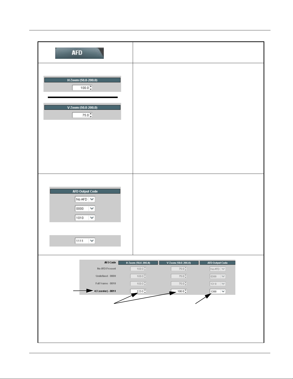
Operating Instructions 9061 Function Submenu List and Descriptions
Table 3-2 9061 Function Submenu List — continued
(continued)
• H Zoom and V Zoom Controls Individual H Zoom and V Zoom controls for each of the 12 AFD code
• AFD Output Code Twelve drop-down lists that allow assignment of AFD codes to the 12
choices for both 4:3 and 16:9 coded input frames described above allow
adjustment of horizontal and vertical zoom percentage for each AFD
code.
(50% to 200% range in 0.1% steps)
Note: To apply H and V settings for a given AFD code using this card,
Scaler Aspect Ratio Conversion must be set to Follow AFD
Settings.
Note: Default zoom percentages use the following rules:
• The default zoom percentages displayed when this function is
accessed are the default percentages corresponding to the
respective AFD standard ratio definitions (for example, default
horizontal and vertical zoom percentages for 4:3 ratios are
correspondingly 133% and 100%, yielding a 4:3 aspect ratio). In
these cases, the null values for this definition are the default values
shown.
• In cases where a different aspect ratio is to be used for a given
received aspect ratio, the default ratio displayed is the null value
that results (assuming no H or V zoom modification). For example,
for a 16:9 signal and settings set for a 1111 (15) AFD code (“16:9
with 4:3 protected image”), the respective displayed default H and V
zoom settings of 100% and 75% protect the Protected Image Area.
individual H Zoom and V Zoom tools described above.
Note: • The default AFD codes displayed when this function is accessed
show the SMPTE AFD code most closely reflecting the aspect
ratio when the corresponding default settings are applied.
• An AFD Output Code setting has no effect on aspect on ARC
performed by this card; it merely applies a selected AFD code to
the output video.
•
•
•
In this example, if a “0011” AFD code is received, the entered
H Zoom and V Zoom values corresponding to AFD code 0011
are applied to the image (133.0% and 100.0%, respectively, in
this example). The H Zoom and V Zoom values for any AFD code
can be changed as desired. When the card Scaler Aspect Ratio
Conversion is set to Follow AFD Settings, the H and V zoom
values set here are applied to the output video.
9061-OM (V4.9) 9061 PRODUCT MANUAL 3-21
In this example, with the AFD Output Code
drop-down set to 1000, if a 0011 code is received
on the input, an AFD code of 1000 is ouputted by
the card. (Note that the assigned output code has
no effect on ARC performed within this card.)
Page 66
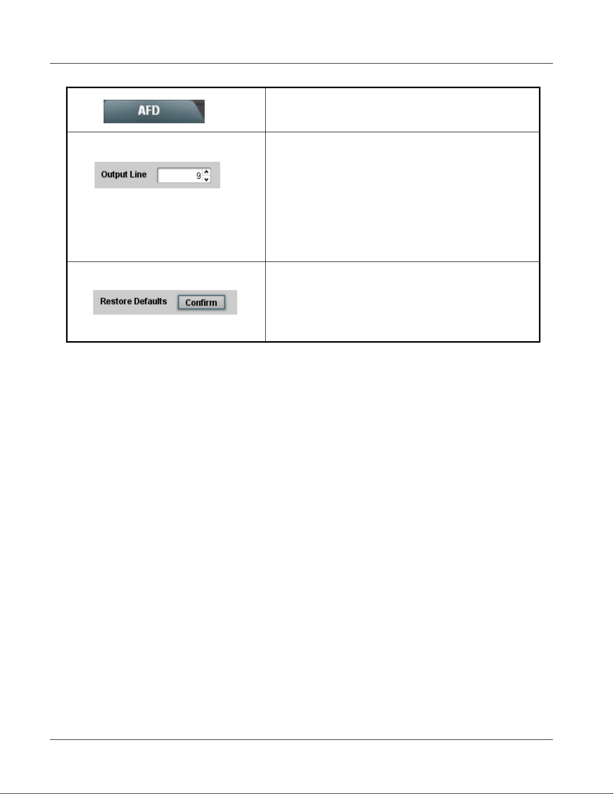
3 9061 Function Submenu List and Descriptions
Table 3-2 9061 Function Submenu List — continued
(continued)
• Output Line Allows selecting the line location of the AFD data within the video signal
• Restore Defaults Restore Defaults provides default restore of all user settings described in
Ancillary Data space.
(Range is 9 thru 41)
Note: • Although the output line drop-down will allow any choice within the
9 thru 41 range, the actual range is automatically clamped (limited)
to certain ranges to prevent inadvertent conflict with active picture
area depending on video format. See Ancillary Data Line Number
Locations and Ranges (p. 3-8) for more information.
• The card does not check for conflicts on a given line number.
Make certain the selected line is available and carrying no other
data.
the remainder of the AFD function description.
When Confirm is clicked, a Confirm? pop-up appears, requesting
confirmation.
• Click Yes to proceed with restore defaults.
• Click No to reject restore defaults.
3-22 9061 PRODUCT MANUAL 9061-OM (V4.9)
Page 67

Operating Instructions 9061 Function Submenu List and Descriptions
Table 3-2 9061 Function Submenu List — continued
Allows Safe Action and/or Safe Title overlays to be
added to the image. The overlays can be used to
identify safe action and safe title areas within the image.
Note: • Overlay markers using this function are for setup only. When enabled, these markers are embedded in the SDI video
output signal and may appear in the image. Use this function only on preview video and not on-air video. Make certain
any overlay tools are turned off when done.
• Overlays are functional only when Scaler is enabled.
• Multiple overlay markers described below can be simultaneously enabled as desired.
• Safe Action Area
When enabled (On), turns on the Safe Action Area overlay.
Overlays
OVERLAY_SAFACT1.0.PNG
When enabled (On), outline shows Safe Action Area boundary.
Color of boundary is selected using Color drop-down list.
• Safe Title Area When enabled (On), turns on the Safe Title Area overlay.
OVERLAY_SAFTLE1.0.PNG
When enabled (On), outline shows Safe Title Area boundary. Color
of boundary is selected using Color drop-down list.
9061-OM (V4.9) 9061 PRODUCT MANUAL 3-23
Page 68
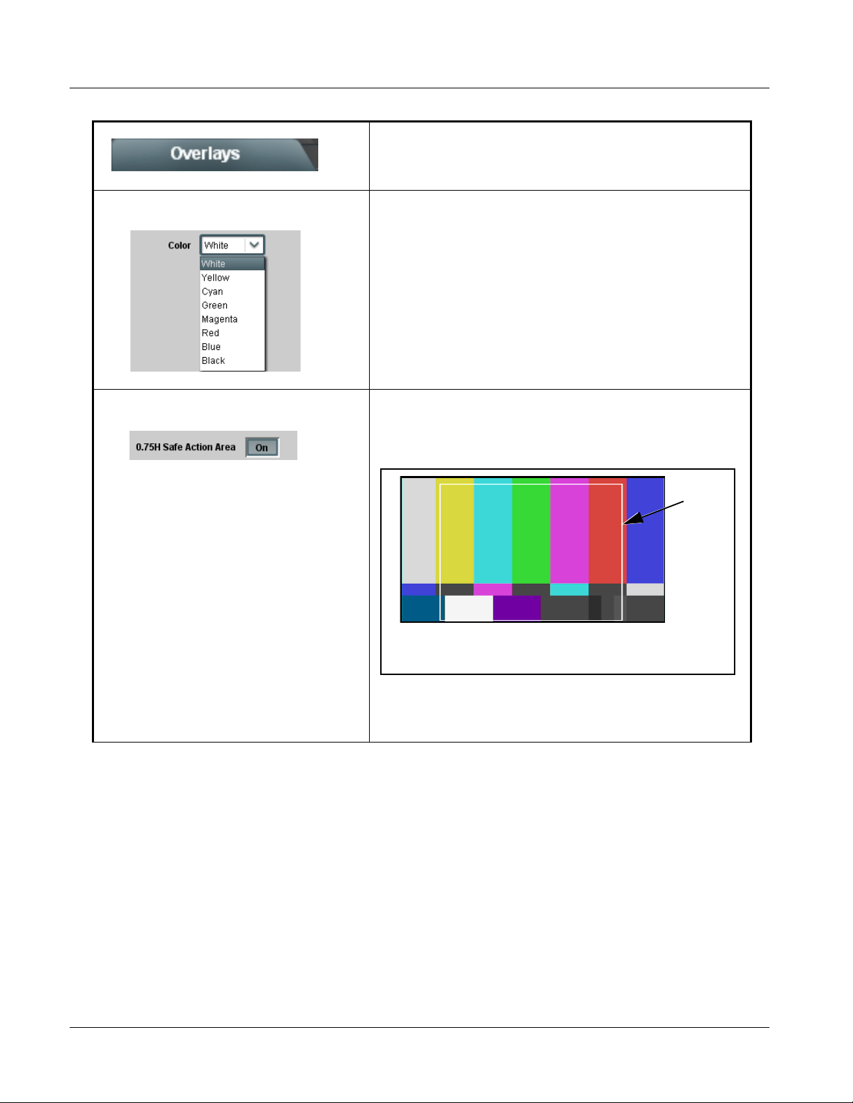
3 9061 Function Submenu List and Descriptions
Table 3-2 9061 Function Submenu List — continued
(continued)
• Safe Action/Title Area Color Selects the Safe Action and Safe Title overlay color from choices shown
• 0.75H Safe Action Area W hen enabled (On), turns on the 0.75H Safe Action Area overlay that
to the left.
shows the 4:3 safe area on a 16:9 image (i.e., the resulting safe area
when the image is converted to 4:3).
OVERLAY_SAFACT_NORMW075.PNG
Outline shows 0.75H Safe Action Area boundary. Color of boundary
is selected using Color drop-down list.
Note: If 0.75H (Pillar Box) is selected using the Aspect Ratio Conversion
tool in the Scaler function, and Overlays Follow ARC is selected
for this function, the overlays will be additionally reduced 0.75H
beyond the standard 4:3 safe areas.
3-24 9061 PRODUCT MANUAL 9061-OM (V4.9)
Page 69
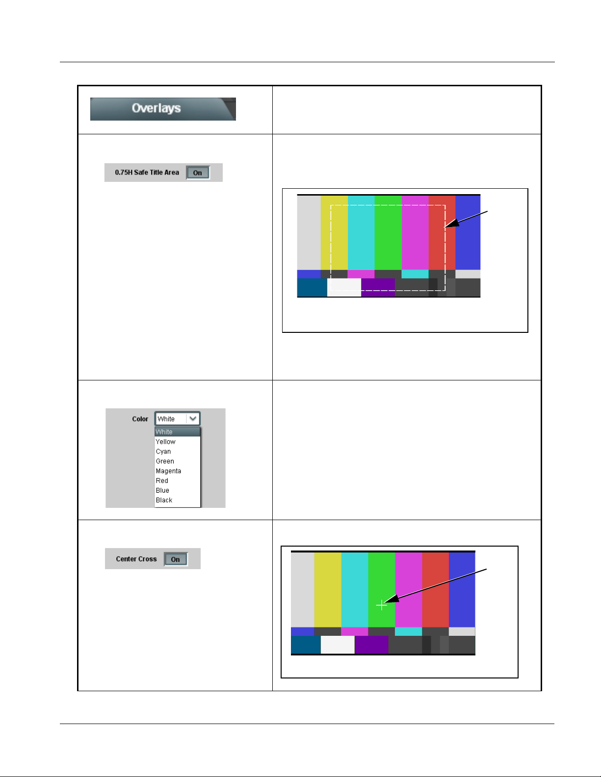
Operating Instructions 9061 Function Submenu List and Descriptions
Table 3-2 9061 Function Submenu List — continued
(continued)
• 0.75H Safe Title Area When enabled (On), turns on the 0.75H Safe Title Area overlay that
shows the 4:3 safe title area on a 16:9 image (i.e., resulting safe title area
when the image is converted to 4:3).
OVERLAY_SAFTLENORMW075.PNG
Outline shows 0.75H Safe Title Area boundary. Color of boundary
is selected using Color drop-down list.
Note: If 0.75H (Pillar Box) is selected using the Aspect Ratio Conversion
tool in the Scaler function, and Overlays Follow ARC is selected
for this function, the overlays will be additionally reduced 0.75H
beyond the standard 4:3 safe areas
• 0.75H Safe Action/Title Area Color Selects the 0.75H Safe Action and 0.75H Safe Title overlay color from
choices shown to the left.
• Center Cross When enabled (On), turns on the Center Cross overlay.
OVERLAY_CTRX.PNG
Color of marker is selected using Color drop-down list.
9061-OM (V4.9) 9061 PRODUCT MANUAL 3-25
Page 70
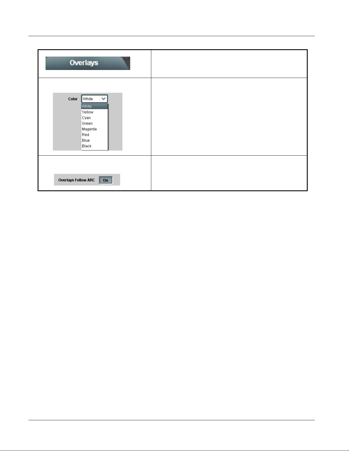
3 9061 Function Submenu List and Descriptions
Table 3-2 9061 Function Submenu List — continued
(continued)
• Center Cross Color Selects the Center Cross overlay color from choices shown to the left.
• Overlays Follow ARC When enabled (On), overlays are resized along with the image in
accordance with any ARC settings.
Note: This choice functions only when a zoom-out is applied (settings
less than 100%).
3-26 9061 PRODUCT MANUAL 9061-OM (V4.9)
Page 71
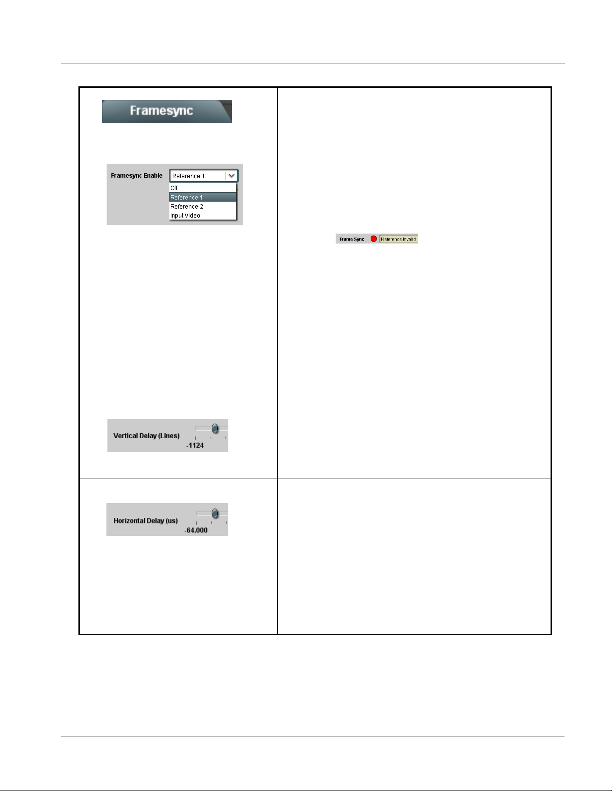
Operating Instructions 9061 Function Submenu List and Descriptions
Table 3-2 9061 Function Submenu List — continued
Provides video Frame Sync delay control and audio
Framesync
• Framesync Enable Disables the Frame Sync function, or selects from choices below.
re-sync tools.
• Off: Video path bypasses frame sync entirely; output video timing
tracks with input video timing.
• Reference 1: Allows Frame Sync function to use external
Reference 1 as the reference (“house”) standard.
• Reference 2: Allows Frame Sync function to use external
Reference 2 as the reference (“house”) standard.
Note: If Reference 1 or Reference 2 is selected and an
appropriate external reference is not received, the
status portion of DashBoard™, indicating invalid frame sync
reference error. (Additionally, the card edge ERR indicator
illuminates indicating the same.) External reference signals
Reference 1 and Reference 2 are distributed to the card
and other cards via a frame bus.
• Input Video: Allows full framesync functionality (such as delay
offset), but instead uses the input video signal as the reference
standard.
Note: • If Input Video is used for framesync, any timing instability
on the input video will result in corresponding instability on
the output video. This setting should only be used where
syncing to input video is known to be reliable.
• Negative vertical or horizontal delay values (using the
controls below) should not be used when using Input
Video mode. This may result in image motion “jerkiness”.
T o add an of fset in t his case, instead apply a positive value
that results in the desired net offset.
indication appears in the Card Info
• Vertical Delay Control When Framesync is enabled, sets vertical delay (in number of lines of
• Horizontal Delay Control When Framesync is enabled, sets (in µsec of output video timing)
output video timing) between the output video and the frame sync
reference.
(Range is -1124 thru 1124 lines.)
Note: Lines refer to lines in the output video format, and not to the
reference format.
horizontal delay between the output video and the frame sync reference.
(Range is -64.000 thru 64.000 µsec)
Note: When an external framesync reference is used, the card will not
produce a framesync reset until the variance between framesync
reference and output video exceeds ± 2 clock periods. Therefore, a
framesync reset will not result if offsets within this window are
applied.
To apply an offset/framesync reset within this window, first apply a
relatively large offset, then apply the target smaller off set.
Example: T o apply a 1-period offset, first apply a 10-period positive
offset and then apply a 9-period negative offset. This results in the
target 1-period offset being applied to the output video.
9061-OM (V4.9) 9061 PRODUCT MANUAL 3-27
Page 72
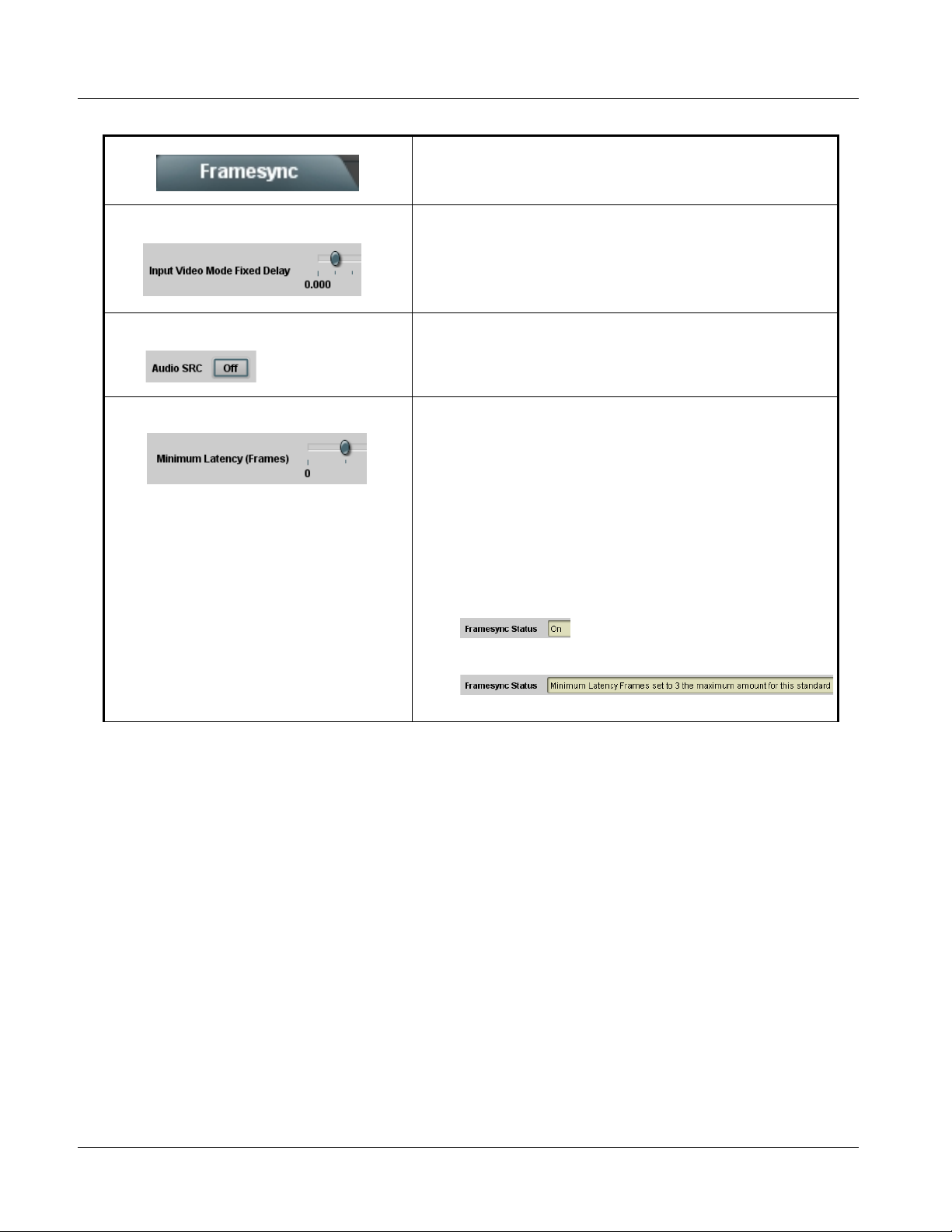
3 9061 Function Submenu List and Descriptions
Table 3-2 9061 Function Submenu List — continued
(continued)
• Input Video Mode Fixed Delay Control When Framesync is enabled and set to Input Video, allows adding video
• Framesync Audio SRC On/Off Control When Framesync is enabled and set to Input Video, allows disabling
• Minimum Latency Frames Control
Minimum Latency Frames Control
delay. This is useful when compensating for processes which result in
large audio delays.
(Range is 0.0000 thru 300.0 msec.)
audio SRC. This is required if the card is to pass non-PCM audio such as
Dolby® audio to downstream devices.
When Framesync is enabled, specifies the smallest amount of latency
allowed by the frame sync (latency measurement in output video frames).
The frame sync will not output a frame unless the specified number of
frames are captured in the buffer. The operational latency of the frame
sync is always between the specified minimum latency and
minimum latency plus one fra m e (not one field).
(Maximum range is 0 to 32.)
Note: Due to card memory limits, the maximum available Minimum
Latency Frames is related to the output video format selected.
For example, with a 525i59.94 output, the practical maximum limit
is 13.
When using this control, be sure to check the Framesync Status
display as follows:
• Latency frames selection within limits.
• Latency frames selection exceeds limits.
3-28 9061 PRODUCT MANUAL 9061-OM (V4.9)
Page 73

Operating Instructions 9061 Function Submenu List and Descriptions
Table 3-2 9061 Function Submenu List — continued
(continued)
• Audio Hard Resync Threshold Control Sets threshold at which hard resync is applied if audio-video offset
With offset less than selected hard resync threshold, resync is progressively applied in many small
steps to provide a seamless, glitch-free retiming. After the successive steps, the audio is synchronized
with the video (in this example, 40 msec). (Progressive correction is applied at 1 msec/sec appr. rate.)
6
Video:
40 msec
With offset greater than selected hard resync
threshold, resync is immediately applied.
Video:
40 msec
Audio:
240 msec
exceeds threshold (see below). Hard resync provides fastest snyc-up
suitable for off-air manipulation. Conversely, a threshold setting high
enough to accommodate normal on-air offsets allows on-air resync that is
glitch-free.
(Range is 1.5 to 13.0 frames in 0.1 frame increments)
9
t
In this example, initial offset of 200 msec (appr. 6 frames) is
below 9 frame threshold and results in soft resync being
progressively applied.
9
In this example, initial offset of 400 msec (appr. 12 frames) is
above 9 frame threshold and results in immediate hard resync.
12
t
Audio:
440 msec
• Audio Offset Control Adds or reduces (offsets) audio delay from the matching video delay
9061-OM (V4.9) 9061 PRODUCT MANUAL 3-29
(audio delay offset setting adds or removes delay in addition to any delay
included by other actions). This control is useful for correcting lip sync
problems when video and audio paths in the chain experience differing
overall delays.
(-575.0 msec to 575.0 msec range; null = 0.0 msec)
Note: Delay offset values of less than approximately 1 frame are
progressively applied by the card to provide a seamless, glitch-free
retiming. However, delay off set values exceeding 1-1/2 f rames may
result in a slight audio discontinuity at the moment when the offset
is applied using this control if the Audio Hard Resync Threshold
control is not at a setting greater than the delay offset.
To prevent this condition during an on-air manipulation, it is
recommended that the Audio Hard Resync Threshold control be
set high enough such that expected delay offsets exceeding 1-1/2
frames are progressively applied.
Note: If using Audio Offset control to perform off-air corrections, it is
recommended to temporarily set the Audio Hard Resync
Threshold control to its minimum setting, thereby allowing the
offset to be assessed and corrected as fast as possible.
Page 74

3 9061 Function Submenu List and Descriptions
Table 3-2 9061 Function Submenu List — continued
(continued)
• Current Audio Delay Display Displays the current input-to-output audio delay (in msec units) as well as
• Video Delay Display Displays the current input-to-output video delay (in msec units) as well as
• Framesync Status Display Displays the current framesync status as follows:
• Loss of Input Signal Selection In the event of input video Loss of Signal (LOS), determines action to be
in terms of Frames/fractional frame (in number of lines).
in terms of Frames/fractional frame (in number of lines).
• Framesync status OK.
• Framesync Enable set to Off.
• I mpr oper or missing framesy nc refere nce.
• Latency frames selection exceeds limits.
Note: See Minimum Latency Frames Control ( p. 3-28) for more
information about this message.
taken as follows:
• Disable Outputs: Disab le all outputs.
• Freeze Last Frame: Freeze image to last good frame (for SDI, last
frame having valid SAV and EAV codes; for analog, last frame free
of timing errors).
• Freeze to Color: Freeze image to a color raster (as selected using
Framesync LOS Freeze Color control).
Note: Freeze Last Frame and Freeze to Color choices are functional only
when frame sync is set to lock to valid reference.
• Framesync LOS Freeze Color In the event of LOS with Freeze to Color enabled above, sets the image
raster color from choices shown to the left.
3-30 9061 PRODUCT MANUAL 9061-OM (V4.9)
Page 75

Operating Instructions 9061 Function Submenu List and Descriptions
Table 3-2 9061 Function Submenu List — continued
(continued)
• Custom Color Hue Adjusts raster hue (phase angle) for custom LOS color.
(-360° to 360° range in 0.1° steps; null = 0°)
• Custom Color Saturation Adjusts raster saturation level for custom LOS color.
(0% to 100% range in 0.1% steps)
• Custom Color Y Level Adjusts raster luma level for custom LOS color.
(64 to 940 range)
• Reset/Resync Framesync
Reset Framesync
Reset Framesync resets the frame sync, clearing any buffered audio and
video.
Resync Video and Reference reset s the input processing paths for video
and reference.
When Confirm is clicked, a Confirm? pop-up appears, requesting
confirmation.
• Click Yes to reset the frame sync.
• Click No to reject reset.
Note: These controls are not normally used or required when the card is
receiving a stable, continuous frame sync reference.
9061-OM (V4.9) 9061 PRODUCT MANUAL 3-31
Page 76

3 9061 Function Submenu List and Descriptions
Table 3-2 9061 Function Submenu List — continued
Selects the audio source for each embedded audio
Embedded Audio Group 1/2
channel 1 thru 8 (Embedded Audio Groups 1 and 2).
Also provides Gain, Phase Invert, and Muting controls
for each channel.
+
Embedded
Audio Group 1
CH1
CH2
CH3
CH4
CH5
CH6
CH7
CH8
Embedded
Audio Group 2
The example above shows
various Source selections and
individual audio control settings
for various audio sources fed to
the Destination channels
Embedded Ch 1 thru
Embedded Ch 8 in Embedded
Audio Groups 1 and 2, with the
resulting setup (right).
The source-to-destination
correlation shown here is only an
example; any of the sources on
the left can connect to any of the
destinations on the right, or to
Embedded Audio Groups 3 and
4 (not shown here). Additional
sources not shown here are also
available. These are described
on the following pages.
The controls shown here are
described in detail on the
following pages.
Embedded
Channels 1 – 16
AES I/O (1-4)
AES IN (5-8)
AN-AUD
IN (1-8)
Embed Ch 12
Embed Ch 14
AES Ch 1
AES Ch 3
AES Ch 5
AES Ch 8
Analog Ch 3
TG1
0 dB
-10 dB
0 dB
+
+
0 dB
+
+
0 dB
+
20 dB
20 dB
15 dB
–
3-32 9061 PRODUCT MANUAL 9061-OM (V4.9)
Page 77

Operating Instructions 9061 Function Submenu List and Descriptions
Table 3-2 9061 Function Submenu List — continued
(continued)
• SD Audio Depth Allows option of using 24-bit audio data structure per SMPTE 272M,
• Group Enable When enabled (On), enables the embedding of the corresponding
§3.10 (default is 20-bit per SMPTE 272M, §3.5).
Note: • If 24-bit depth is desired, make certain downstream equipment is
compatible with 24-bit SD audio data.
• Depth control setting applied here affects both Embedded Audio
Group 1/2 and 3/4.
embedded audio group (Embedded Audio Group 1 or Embedded Audio
Group 2).
• Embedded Audio Group 1 consists of embedded channels 1 thru 4.
• Embedded Audio Group 2 consists of embedded channels 5 thru 8.
Two Group Enable buttons correspondingly enable or disable Embedded
Audio Group 1 and Embedded Audio Group 2.
Disabling a group removes the entire group of embedded audio channels
while preserving the settings of the channels belonging to the group.
Note: • Embedded Ch 2 th ru Embedded Ch 8 have controls identical to the Source, Gain, Mute, and Phase controls
described here for Embedded Ch 1. Therefore, only the Embedded Ch 1 controls are shown here.
• For each channel, its source and destination should be considered and appropriately set. Unused destination
channels should be set to the Silence selection.
• Embedded Channel Sourc e Using the Source drop-down list, selects the audio input source to be
embedded in the corresponding embedded channel from the choices
described below.
• Embedded Ch 1 thru Ch 16 as Source Embed Ch 1 thru Embed Ch 16 range in Source drop-down list enables
•
•
•
• AES Ch 1 thru AES Ch 16 as Source AES Ch 1 thru AES Ch 16 range in Source drop-down list enables a
•
•
•
an embedded channel (Ch 1 thru Ch 16) to be the source for the selected
destination Embedded Audio Group channel.
(In this example, Embed Ch 1 (embedded Ch 1) is the source for
destination Embedded Ch 1)
discrete AES channel (Ch 1 thru Ch 16) to be the source for the selected
destination Embedded Audio Group channel.
(In this example, AES Ch 1 is the source for destination Embedded Ch 1)
9061-OM (V4.9) 9061 PRODUCT MANUAL 3-33
Page 78

3 9061 Function Submenu List and Descriptions
Table 3-2 9061 Function Submenu List — continued
(continued)
• An alog Ch 1 thru Ch 8 as Source Analog Ch 1 thru Analog Ch 8 range in Source drop-down list enables a
•
•
•
• Do wn Mix Left or Right as Source Down Mix Left and Down Mix Right selections in Source drop-down list
• M o no Mi x as Source Mono selection in Source drop-down list allows mono mix content to be
balanced-input analog channel (Ch 1 thru Ch 8) to be the source for the
selected destination Embedded Audio Group channel.
(In this example, Analog Ch1 is the source for destination
Embedded Ch 1)
allow either downmixer left or right channel to be the source for the
selected destination Embedded Audio Group channel.
(In this example, the Down Mix Left channel is the source for destination
Embedded Ch 1)
Note: Down Mix Left and Down Mix Right channels are a stereo pair
derived from the L, C, R, Ls, and Rs channel inputs selected using
the Audio Mixing function. The stereo pair consists of basic L/R
PCM signals with no additional encoded information.
Refer to Audio Mixing function description on page 3-50 for more
information.
the source for the selected destination Embedded Audio Group channel.
(In this example, the mono content is the source for destination
Embedded Ch 1)
Note: Mono mix content is set up using Mono Mixer Selection in the
Audio Mixing function). Refe r to Audio Mixing function
description on page 3-50 for more information.
• Audio LTC as Source LTC selection in Source drop-down list allows any timecode format
• Tone Generator 1 thru 4 as Source Tone Generato r 1 thru Tone Generator 4 range in Source drop-down list
received by the card to be outputted as audio LTC over an embedded
audio output (destination) channel.
(In this example, audio LTC is the source for destination Embedded Ch 1)
Note: • When LTC is selected as source, Gain and Mute controls are
disabled.
• Refer to Timecode function description on page 3-46 for mor e
information.
enables one of four tone generators (Tone 1 thru Tone 4) to be the source
for the selected destination Embedded Audio Group channel.
(In this example, Tone 1 (tone generator 1) is the source for destination
Embedded Ch 1)
Note: Tone generator frequencies can be independently set for the four
tone generator sources.
Refer to Tone Generator function description on page 3-55 for
more information.
3-34 9061 PRODUCT MANUAL 9061-OM (V4.9)
Page 79

Operating Instructions 9061 Function Submenu List and Descriptions
Table 3-2 9061 Function Submenu List — continued
(continued)
• Silence (Mute) as Source Silence selection in Source drop-down list mutes the selected destination
• Gain (dB) Control Adjusts and displays relative gain (in dB) applied to the corresponding
• Mute Control Allows pushbutton On/Off channel muting while saving all other settings.
Embedded Audio Group channel. Use this setting for unused
destination channels.
(In this example, silence (muting) is applied to Embedded Ch 1)
destination Embedded Audio Group channel.
(-80 to +40 dB range in 0.1 dB steps; unity = 0.0 dB)
• Phase Control Selects between Normal and Invert phase (relative to source original
phase) for the destination Embedded Audio Group channel.
9061-OM (V4.9) 9061 PRODUCT MANUAL 3-35
Page 80
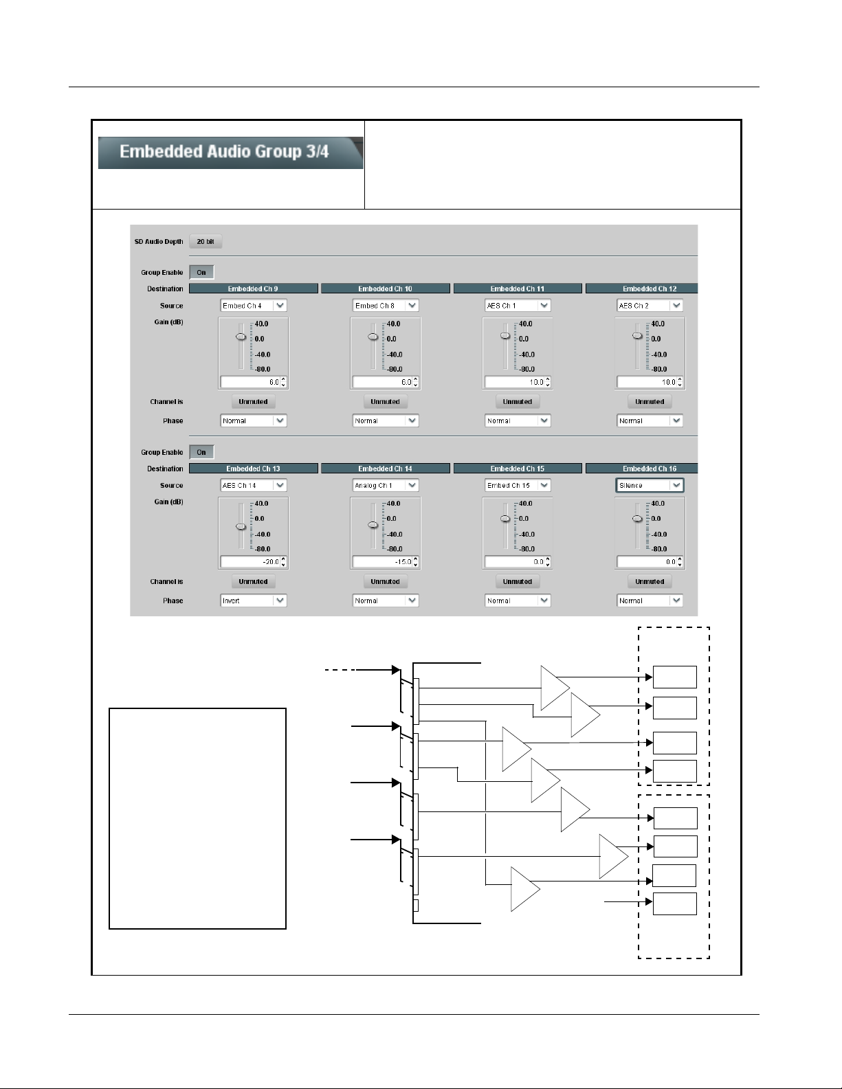
3 9061 Function Submenu List and Descriptions
Table 3-2 9061 Function Submenu List — continued
Selects the audio source for each embedded audio
Embedded Audio Group 3/4
channel 9 thru 16 (Embedded Audio Groups 3 and 4).
Also provides Gain, Phase Invert, and Muting controls
for each channel.
+
Embedded
Audio Group 3
CH9
CH10
CH11
CH12
CH13
CH14
CH15
CH16
Embedded
Audio Group 4
The example above shows
various Source selections and
individual audio control settings
for various audio sources fed to
the Destination channels
Embedded Ch 9 thru
Embedded Ch 16 in Embedded
Audio Groups 3 and 4, with the
resulting setup (right).
The source-to-destination
correlation shown here is only
an example; any of the sources
on the left can connect to any of
the destinations on the right, or
to Embedded Audio Groups 1
and 2 (not shown here).
Additional sources not shown
here are also available.
Embedded
Channels 1 – 16
AES I/O (1-4)
AES IN (5-8)
AN-AUD
IN (1-8)
Embed Ch 4
Embed Ch 8
Embed Ch 15
AES Ch 1
AES Ch 2
AES Ch 14
Analog Ch 1
+
6 dB
+
6 dB
+
10 dB
+
10 dB
–20 dB
–
–15 dB
+
0 dB
Silence
3-36 9061 PRODUCT MANUAL 9061-OM (V4.9)
Page 81

Operating Instructions 9061 Function Submenu List and Descriptions
Table 3-2 9061 Function Submenu List — continued
(continued)
• SD Audio Depth Allows option of using 24-bit audio data structure per SMPTE 272M,
• Group Enable
§3.10 (default is 20-bit per SMPTE 272M, §3.5).
Note: • If 24-bit depth is desired, make certain downstream equipment is
compatible with 24-bit SD audio data.
• Depth control setting applied here affects both Embedded Audio
Group 1/2 and 3/4.
When enabled (On), enables the embedding of the corresponding
embedded audio group (Embedded Audio Group 3 or Embedded Audio
Group 4).
• Embedded Audio Group 3 consists of embedded channels 9 thru 12.
• Embedded Audio Group 4 consists of embedded channels 13 thru 16.
Two Group Enable buttons correspondingly enable or disable Embedded
Audio Group 3 and Embedded Audio Group 4.
Disabling a group removes the entire group of embedded audio channels
while preserving the settings of the channels belonging to the group.
Note: • Embedded Ch 9 thru Embedded Ch 16 have controls that are identical to the Source, Gain, Mute, and Phase controls
described for Embedded Ch 1. Refer to Embedded Audio Group 1/2 on page 3-32 for descriptions of these controls.
• For each channel, its source and destination should be considered and appropriately set. Unused destination channels
should be set to the Silence selection.
9061-OM (V4.9) 9061 PRODUCT MANUAL 3-37
Page 82
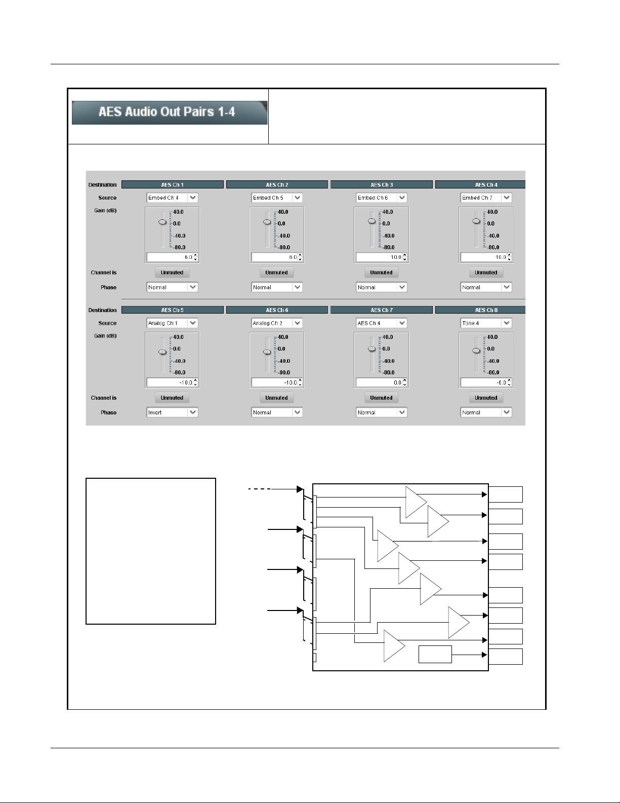
3 9061 Function Submenu List and Descriptions
Table 3-2 9061 Function Submenu List — continued
Routes audio sources to discrete AES output channels
1 thru 8 (AES Audi o Out Pai rs 1-4 ). Al so pr ovid es Ga in,
AES Audio Out Pairs 1-4
Phase Invert, and Muting controls for each channel.
The example above shows
various Source selections and
individual audio control settings
for various audio sources fed to
the Destination channels
AES Ch 1 thru AES Ch 8, with
the resulting setup (right).
The source-to-destination
correlation shown here is only
an example; any of the sources
on the left can connect to any of
the destinations on the right.
The controls shown here are
described in detail on the
following pages.
Embedded
Channels 1 – 16
AES I/O (1-4)
AES IN (5-8)
AN-AUD
IN (1-8)
Embed Ch 4
Embed Ch 5
Embed Ch 6
Embed Ch 7
AES Ch 4
Analog Ch 1
Analog Ch 2
10 dB
0 dB
+
10 dB
+
6 dB
AES Audio Out
Pairs 1-4
(Ch 1-8)
+
+
6 dB
+
–10 dB
–
–10 dB
–6 dB
TG4
AES Ch 1
AES Ch 2
AES Ch 3
AES Ch 4
AES Ch 5
+
AES Ch 6
AES Ch 7
AES Ch 8
3-38 9061 PRODUCT MANUAL 9061-OM (V4.9)
Page 83
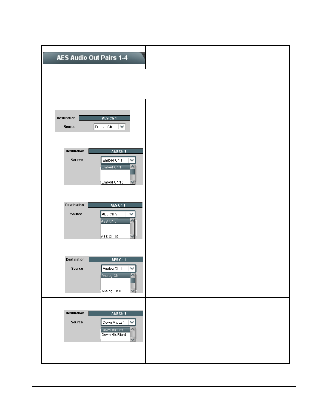
Operating Instructions 9061 Function Submenu List and Descriptions
Table 3-2 9061 Function Submenu List — continued
(continued)
Note: • AES Ch 2 thru AES Ch 8 have controls that are identical to the Source, Gain, Mute, and Phase controls described
here for AES Ch 1. Therefore, only the AES Ch 1 controls are shown here.
• For each channel, its source and destination should be considered and appropriately set. Unused destination channels
should be set to the Silence selection.
• AES Channel Source Using the Source drop-down list, selects the audio source to be routed to
• Embedded Ch 1 thru Ch 16 as Source
•
•
•
• AES Ch 1 thru AES Ch 16 as Source AES Ch 1 thru AES Ch 16 range in Source drop-down list enables a
•
•
•
• Analog Ch 1 thru Ch 8 as Source Analog Ch 1 thru Analog Ch 8 range in Source drop-down list enables a
the corresponding AES output channel from the choices described below.
Embed Ch 1 thru Embed Ch 16 range in Source drop-down list enables
an embedded channel (Ch 1 thru Ch 16) to be the source for the selected
destination AES channel.
(In this example, Embed Ch 1 (embedded Ch 1) is the source for
destination AES Ch 1)
discrete AES channel (Ch 1 thru Ch 16) to be the source for the selected
destination AES channel.
(In this example, AES Ch 5 is the source for destination AES Ch 1)
balanced-input analog channel (Ch 1 thru Ch 8) to be the source for the
selected destination AES channel.
(In this example, Analog Ch1 is the source for destination AES Ch 1)
•
•
•
• Down Mix Left or Right as Source Down Mix Left and Down Mix Right selections in Source drop-down list
9061-OM (V4.9) 9061 PRODUCT MANUAL 3-39
allow either downmix left or right channel to be the source for the selected
destination AES channel.
(In this example, the Down Mix Left channel is the source for destination
AES Ch 1)
Note: Down Mix Left and Down Mix Right channels are a stereo pair
derived from the L, C, R, Ls, and Rs channel inputs selected using
the Audio Mixing function. The stereo pair consists of basic L/R
PCM signals with no additional encoded information.
Refer to Audio Mixing function description on page 3-50 for more
information.
Page 84
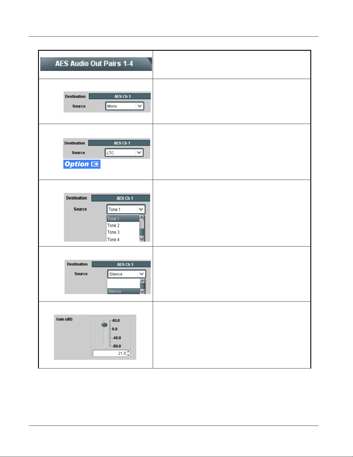
3 9061 Function Submenu List and Descriptions
Table 3-2 9061 Function Submenu List — continued
(continued)
• M o no Mi x as Source Mono selection in Source drop-down list allows mono mix content to be
• Audio LTC as Source LTC selection in Source drop-down list allows any timecode format
• Tone Generator 1 thru 4 as Source Tone Generato r 1 thru Tone Generator 4 range in Source drop-down list
the source for the selected destination AES channel.
(In this example, the mono content is the source for destination AES Ch 1)
Note: Mono mix content is set up using Mono Mixer Selection in the
Audio Mixing function). Refe r to Audio Mixing function
description on page 3-50 for more information.
received by the card to be outputted as audio LTC over an AES audio
output (destination) channel.
(In this example, audio LTC is the source for destination AES Ch 1)
Note: • When LTC is selected as source, Gain and Mute controls are
disabled.
• Refer to Timecode function description on page 3-46 for mor e
information.
enables one of four tone generators (Tone 1 thru Tone 4) to be the source
for the selected destination AES channel.
(In this example, Tone 1 (tone generator 1) is the source for destination
AES Ch 1)
Note: Tone generator frequencies can be independently set for the four
tone generator sources.
Refer to Tone Generator function description on page 3-55 for
more information.
• Silence (Mute) as Source Silence selection in Source drop-down list mutes the selected destination
• Gain (dB) Control Adjusts and displays relative gain (in dB) applied to the corresponding
AES channel. Use this setting for unused destination channels.
(In this example, silence (muting) is applied to AES Ch 1)
destination AES channel.
(-80 to +40 dB range in 0.1 dB steps; unity = 0.0 dB)
3-40 9061 PRODUCT MANUAL 9061-OM (V4.9)
Page 85
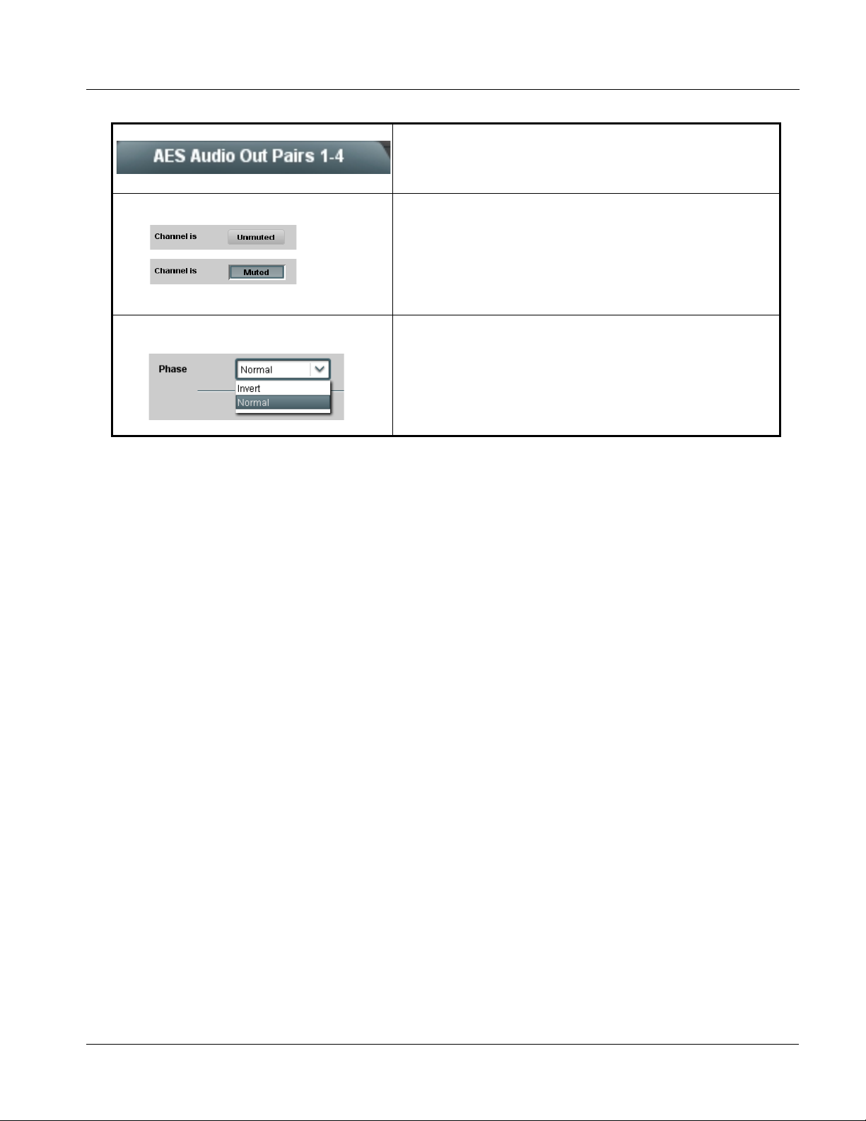
Operating Instructions 9061 Function Submenu List and Descriptions
Table 3-2 9061 Function Submenu List — continued
(continued)
• Mute Control Allows pushbutton On/Off channel muting while saving all other settings.
• Phase Control Selects between Normal and Invert phase (relative to source original
phase) for the destination AES output channel.
9061-OM (V4.9) 9061 PRODUCT MANUAL 3-41
Page 86
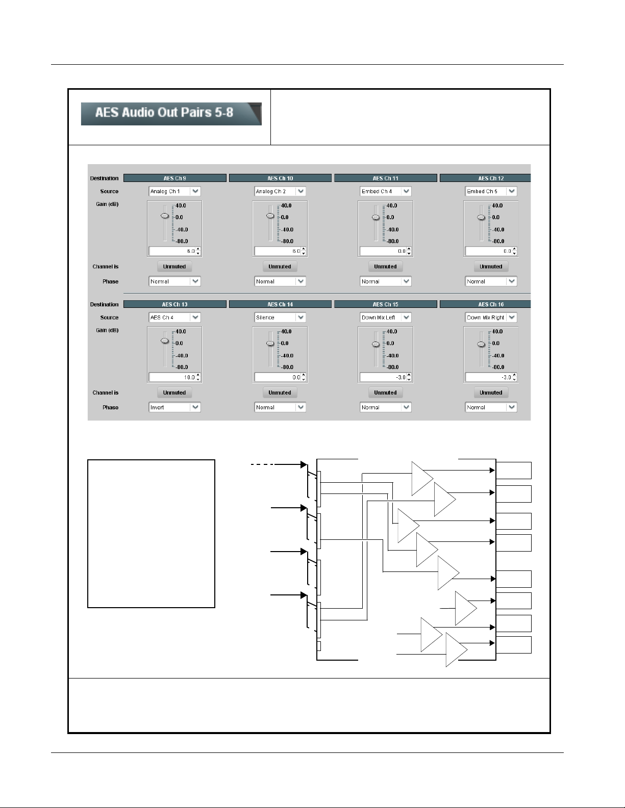
3 9061 Function Submenu List and Descriptions
Table 3-2 9061 Function Submenu List — continued
Routes audio sources to AES output channels 9 thru 16
(AES Audi o Ou t Pa ir s 5 -8 ). A lso provides Gain, Muti n g,
AES Audio Out Pairs 5-8
and Phase Invert controls for each channel.
+
AES Audio Out
Pairs 5-8
(Ch 9-16)
AES Ch 9
AES Ch 10
AES Ch 11
AES Ch 12
AES Ch 13
AES Ch 14
AES Ch 15
AES Ch 16
The example above shows
various Source selections and
individual audio control settings
for various audio sources fed to
the Destination channels AES
Ch 9 thru AES Ch 16, with the
resulting setup (right).
The source-to-destination
correlation shown here is only
an example; any of the sources
on the left can connect to any of
the destinations on the right, or
receive sources. Available
sources also include up to four
tone generators (not shown
here).
Embedded
Channels 1 – 16
AES I/O (1-4)
AES IN (5-8)
AN-AUD
IN (1-8)
Embed Ch 4
Embed Ch 5
AES Ch 4
Analog Ch 1
Analog Ch 2
Down Mix L
Down Mix R
0 dB
6 dB
+
0 dB
Silence
–3 dB
+
+
6 dB
+
10 dB
–
0 dB
+
+
–3 dB
Note: • AES Ch 9 thru AES Ch 16 have controls that are identical to the Source, Gain, Mute, and Phase controls described
for AES Ch 1. Refer to AES Audio Out Pairs 1-4 on page3-38 for descriptions of these controls.
• For each channel, its source and destination should be considered and appropriately set. Unused destination channels
should be set to the Silence selection.
3-42 9061 PRODUCT MANUAL 9061-OM (V4.9)
Page 87
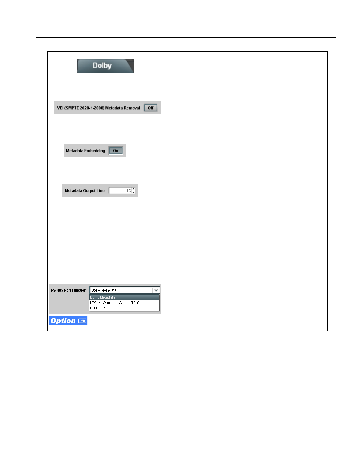
Operating Instructions 9061 Function Submenu List and Descriptions
Table 3-2 9061 Function Submenu List — continued
Extracts and preserves Dolby® metadata from the input
SDI, and in turn allows the metadata to be re-inserted in
Dolby Metadata
the output SDI. This allows scaling and/or format
conversions without losing Dolby
®
metadata.
• VBI Metadata Removal VBI Metadata Removal (On/Off) allows metadata to be removed (On)
• Metadata Embedding Metadata Embedding (On/Off) controls SMPTE 2020-1 metadata
• Metadata Output Line
even if the Scaler is not enabled. (This control is default set to Off, with
metadata being passed when Scaler is disabled)
Note: When the Scaler is enabled, Dolby metadata is automatically
removed. Set the Metadata Embedding control to On to re-insert
metadata as described above.
embedding in the SDI video output.
• When set to On, metadata is extracted from the SDI input video,
buffered, and re-directed to the output SDI video.
• When set to Off, metadata is not embedded in the output SDI video.
Allows selection of SMPTE 2020-1 metadata
space for re-inserted Dolby® metadata.
(Range is 9 thru 41)
Note: • Although the output line drop-down will allow any choice within the
9 thru 41 range, the actual range is automatically clamped (limited
to) certain ranges to prevent inadvertent conflict with active
picture area depending on video format. See Ancillary Data Line
Number Locations and Ranges (p. 3-8) for more information.
• The card does not check for conflicts on a given line number.
Make certain the selected line is available and carrying no other
data unless existing metadata is to be intentionally overwritten.
line location within the VANC
Note: The Metada ta Output Source button in DashBoard™ is locked to Input Video for this card. With this function enabled,
the extracted metadata is always available in the SDI video output and on cards equipped with an appropriate Rear I/O
Module having a Dolby
®
metadata RS-485 connector.
• RS-485 Port Function Select Selects function for shared RS-485 on card with +LTC option. For Dolby
metadata output on port, make sure control is set as shown here.
9061-OM (V4.9) 9061 PRODUCT MANUAL 3-43
®
Page 88
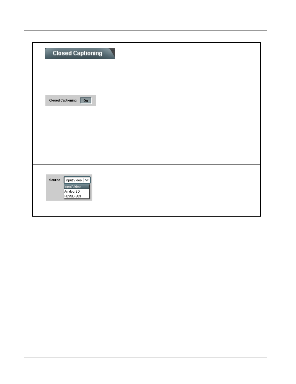
3 9061 Function Submenu List and Descriptions
Table 3-2 9061 Function Submenu List — continued
Provides support for closed captioning setup.
Note: When receiving HD-SDI, both CEA 608 and CEA 708 are supported, with CEA 608 and CEA 708 (containing CEA 608
packets) converted to line 21 closed captioning on outputs down-converted to SD (on up-convert of SD, only CEA 608
closed captioning is generated).
• Closed Captioning On/Off T urns on or turns off the Closed Captioning on the output.
Note: • When set to On, closed captioning is set to standard default line
number. See Ancillary Data Line Number Locations and Ranges
(p. 3-8).
• The card does not check for conflicts on a given line number.
Make certain selected line is available and carrying no other data.
• Closed captioning line may contain active unintended data even if
closed captioning is set to Off. If closed captioning is not to be
used, it is recommended to use the Top Line Suppression
control to eliminate the possibility of this unintended data from
appearing in the active video area. (See Scaler tab (p. 3-14) Top
line suppression control for more details.)
• Closed captioning On/Off will not remove existing packets unless
the Scaler is enabled. To remove packets without changing output
format, set Scaler to Enabled and HD:Convert to: to Same as
Input. (See Scaler tab (p. 3-14) T op line suppression control f or
more details.)
• Closed Captioning Source
Closed Captioning
Selects the video format that carries the Closed Captioning (CC) video
stream as follows:
• Input Video: Sets the 9061 to receive CC stream from the currently
selected input format (as selected using the Video Signal Controls
functions.
• Analog SD: Sets the 9061 to receive analog SD CC stream on the
analog inputs (Y/composite, Pr/C, and Pb inputs) regardless of
video input source.
• HD/SD-SDI: Sets the 9061 to receive either HD or SD CC stream on
the SDI input regardless of video input source.
3-44 9061 PRODUCT MANUAL 9061-OM (V4.9)
Page 89
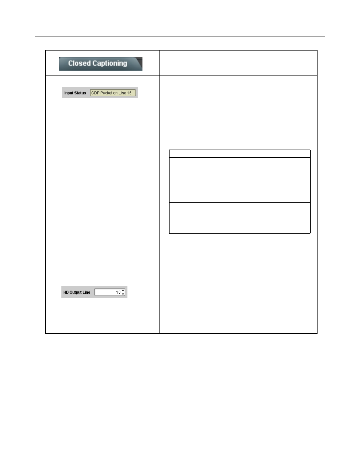
Operating Instructions 9061 Function Submenu List and Descriptions
Table 3-2 9061 Function Submenu List — continued
(continued)
• Closed Cap t i oning Input Status Displays incoming Closed Captioning status as follows:
• If closed captioning is present, a message similar to the example shown
left is displayed. Also displayed is the VANC line number of the incoming
closed captioning packet (or SD waveform-based VANC line number).
• If no closed captioning is present in the video signal, Not Present or
Disabled is displayed.
Note: • Packet closed captioning status Captioning Rejected Due To
message can appear due to the items described below. The
closed captioning function assesses cdp_identifier,
cdp_frame_rate, ccdata_present, and caption_service_active
items contained in the packet header to make the determinations
listed below. Refer to CEA-708-B for more information.
Message Description
Unsupported Frame Rate F ilm rate closed-capt ioning
Data Not Present Packet is marked from closed
No Data ID Packet from closed captioning
(either as pass-through or up/
down conversion) is not
supported by the card.
captioning source external to the
card that no data is present.
source external to the card is not
properly identified with 0x9669
as the first word of the header
(unidentified packet).
• caption service is marked as inactive display indicates bit in
packet from upstream source may inadvertently be set as
inactive. In this case, closed captioning data (if present) is still
processed and passed by the card as normal.
• The closed captioning function does not support PAL closed
captioning standards.
• Closed Captioning HD Output Line Selects the VANC line number (9 thru 41) for the closed caption data
when the output is HD.
Note: • Although the output line drop-down will allow any choice within the
9 thru 41 range, the actual range is automatically clamped (limited
to) certain ranges to prevent inadvertent conflict with active
picture area depending on video format. See Ancillary Data Line
Number Locations and Ranges (p. 3-8) for more information.
• The card does not check for conflicts on a given line number.
Make certain the selected line is available and carrying no other
data unless existing metadata is to be intentionally overwritten.
9061-OM (V4.9) 9061 PRODUCT MANUAL 3-45
Page 90

3 9061 Function Submenu List and Descriptions
Table 3-2 9061 Function Submenu List — continued
Provides timecode data extraction from various
sources, and provides formatting and re-insertion
Timecode
Shown below is an example in which received 525i 5994 SDI video is being converted to 720p 5994. To preserve and re-insert
the timecode data, the following can be performed using the Timecode function. Each Timecode control is fully described on
the pages that follow.
controls for inserting the timecode into the output video.
525i 5994
w/ VITC
Waveform
A
Noting that the incoming video contains VITC
9061
720p 5994
w/ ATC_VITC
w/ ATC_LTC
waveform timecode data (as shown in the status
display), set the Source Priority drop-down lists to
include VITC Waveform timecode data (SDI VITC) as
a choice. This extracts VITC Waveform timecode
data from the incoming video.
In this example, it is desired to provide both SDI
B
ATC_VITC and ATC_LTC timecode data in the
converted HD output video. As such, set both
HD ATC VITC Insertion and HD ATC LTC Insertion
to Enabled.
In the example here, the line numbers are set to the
default SMPTE 12M-2-2008 recommended values.
Analog VITC
Detect/Extract
525i SDI
w/ VITC
Waveform
SDI VITC
Detect/Extract
A
A
Priority/
Select
Buffer/
Format
SDI VITC
Timecode
Proc/Embed
ATC_VITC
Timecode
Proc/Embed
B
SDI ATC_VITC
Detect/Extract
SDI ATC_LTC
Detect/Extract
LTC Detect/
Extract
Insert
Control
Number
Control
Line
ATC_LTC
Timecode
Proc/Embed
ATC_VITC Insertion = Enabled
ATC_LTC Insertion = Enabled
ATC_VITC1 = Line 9 (default SMPTE 12M-2)
ATC_VITC2 = Line 8 (571) (default SMPTE 12M-2)
ATC_LTC = Line 10 (default SMPTE 12M-2)
B
720p SDI
w/ATC_VITC
w/ATC_LTC
3-46 9061 PRODUCT MANUAL 9061-OM (V4.9)
Page 91

Operating Instructions 9061 Function Submenu List and Descriptions
Table 3-2 9061 Function Submenu List — continued
(continued)
Audio LTC and RS-485 LTC controls described below only appear on cards with +LTC licensed optional
feature. This feature allows bidirectional conversion between VBI-based timecode and LTC timecode on audio and RS-485
interfaces.
Refer to Examples Using Audio LTC and RS-485 LTC Features (p. 3-62) for more information and examples of setting card to
receive or send audio LTC and RS-485 LTC.
• Timecode Source Status Displays Displays the current status and contents of the supported timecode
• RS-485 Port LTC Control Allows RS-485 port to be used to receive LT C, or send LTC over RS-485
formats shown to the left.
• If a format is receiving timecode data, the current content (timecode
running count and line number) is displayed.
• If a format is not receiving timecode data, Unlocked is displayed.
• If Audio LTC is being received, the timecode running count is
displayed.
• Audio LTC Source selects audio source to be used by card audio
LTC function as listed below.
• Emb Ch 1 thru Ch 16
• AES Ch 1 thru Ch 16
• Analog audio Ch 1 thru Ch 8
Note: Audio LTC Source must be appropriately set for card to receive
and process audio LTC.
port as follows:
• If RS-485 L TC is to be received via the shared RS-485 port, set the
RS-485 Port Function control to LTC In.
• If RS-485 LTC is to be outputted via the shared RS-485 port, set
the RS-485 Port Function control to LTC Output. The timecode
string carried on the LTC output is that selected using the Source
Priority controls described on the next page.
• Incoming ATC Packet Removal Control Enables or disables removal of existing input video ATC timecode packets
9061-OM (V4.9) 9061 PRODUCT MANUAL 3-47
from the output. This allows removal of undesired existing timecodes from
the output, resulting in a “clean slate” where only desired timecodes are
then re-inserted into the output. (For example, if both SDI ATC_VITC and
ATC_LTC are present on the input video, and only ATC_LTC is desired,
using the Removal control will remove both timecodes from the output.
The ATC_LTC timecode by itself can then be re-inserted on the output
using the other controls discussed here.)
Note: When the Scaler is enabled, ATC packets are automatically
removed. The Timecode function must be used to re-insert the
timecode data into the output video.
Page 92

3 9061 Function Submenu List and Descriptions
Table 3-2 9061 Function Submenu List — continued
(continued)
• Source Priority As described here, provides 4-level prioritization of timecode format
choices from choices shown to the left.
Source Priority 1 thru Source Priority 4 select the preferred format to be
used in descending order (i.e., Source Priority 2 selects the second-most
preferred format, and so on. See example below.)
Analog VITC
SDI VITC
ATC_LTC HD SDI ATC_LTC
ATC_VITC SD/HD SDI ATC_VITC
Audio LTC
VITC waveform from analog
video input
VITC waveform from SD SDI
video input
Audio-based LTC from
selected c ard audio input
channel
HD/SD
525i
SDI VITC
(1st priority)
525i
ANLG VITC
(2nd priority)
In this exam ple, SDI VITC 1st priority selection selects SDI VITC (received on SDI
input) over analog VITC (received on analog input) regardless of video input
material source to be processed by the card.
The selected timecode source is embedded on the SDI video output (in this
example, 720p) using the selected line number. In this example, if the SDI VITC
on the SDI input becomes unavailable, the card then uses the 525i analog VITC
data received on the card analog video input.
Note: If analog VITC timecode source contains 7.5 IRE of setup, make certain
Video Signal Control s –> NTSC Contains is set to 7.5 IRE of Setup. If
this is not done, analog VITC waveform may not be received and
processed by the card.
SDI IN
TC
ANLG IN
SDI
OUT
720p
(w/ ATC_VITC)
• Output Stat us Dis play Di splays the current content and source being used for the timecode data
as follows:
• O utput status OK (in this example, SDI VITC timecode received and
outputted).
• Timecode Insertion button set to Disabled; output insertion disabled.
Note: • If timecode is not available from Source Priority selections
performed, timecode on output reverts to Free Run (internal
count) mode.
• Because the 1’s digit of the display Frames counter goes from 0 to
29, the fractional digit (along with the 1’s digit) indicates frame
count as follows:
0.0 Frame 0
0.1 Frame 1
1.0 Frame 2
1.1 Frame 3
•
•
•
29.1 Frame 59
• Offset Contr ols Allows the current timecode count to be advanced or delayed on the
output video.
• Offset Advance or Delay selects offset advance or delay.
• Offset Field delays or advances or delays timecode by one field.
• Offset Frame delays or advances or delays timecode by up to 5
frames.
Note: Default settings are null, with both controls set at zero as shown.
3-48 9061 PRODUCT MANUAL 9061-OM (V4.9)
Page 93

Operating Instructions 9061 Function Submenu List and Descriptions
Table 3-2 9061 Function Submenu List — continued
(continued)
Note:
• Although the output line drop-down on the controls described below will allow a particular range of choices, the actual
range is automatically clamped (limited) to certain ranges to prevent inadvertent conflict with active picture area
depending on video format. See Ancillary Data Line Number Locations and Ranges (p. 3-8) for more information.
• The card does not check for conflicts on a given line number. Make certain the selected line is available and carrying
no other data.
• Insertion controls described below enable or disable insertion on output video only when the Scaler is enabled.
Existing waveform or packet-based data on an unscaled stream are not affected by these controls and are passed on
the SDI output.
• SD VITC Waveform Insertion Controls For SD output, enables or disables SD VITC waveform timecode insertion
• SD ATC Insertion Control For SD output, enables or disables SD ATC_VITC timecode insertion into
• HD ATC_LTC Insertion Control For HD output, enables or disables ATC_LTC timecode insertion into the
• HD ATC_VITC Insertion Control
into the output video, and selects the VITC1 and VITC2 line numbers (6
thru 22) where the VITC waveform is inserted.
Note: • If only one output line is to be used, set both controls for the same
line number.
• SD VITC Waveform Insertion control only affects VITC
waveforms inserted (or copied to a new line number) by this
function.
the output video, and selects the line number for ATC_VITC.
output video, and selects the line number for ATC_LTC timecode data.
For HD output, enables or disables ATC_VITC timecode insertion into the
output video, and selects the line number for ATC_VITC1 and
ATC_VITC2.
Note: If only one output line is to be used, set both controls for the same
line number.
• ATC_VITC Legacy Support Control When enabled, accommodates equipment requiring ATC_VITC packet in
9061-OM (V4.9) 9061 PRODUCT MANUAL 3-49
both fields as a “field 1” packet (non-toggling).
Note: Non-toggling VITC1 and VITC2 packets do not conform to
SMPTE 12M-2-2008 preferences. As such, ATC_VITC Legacy
Support should be enabled only if required by downstream
equipment.
Page 94

3 9061 Function Submenu List and Descriptions
Table 3-2 9061 Function Submenu List — continued
Provides down-mix audio routing selections that
multiplexes any five embedded, AES, or analog audio
Audio Mixing
channel sources into a stereo pair (Down Mix Left and
Down Mix Right), or selection of any two audio sources
to be mono-mixed to serve as a monaural source.
With an optional upmixer licensable feature activated,
any normal PCM stereo pair can be fed to the upmixer to
generate 5.1 surround sound audio which in turn can be
applied to six user-selectable channels.
• Down Mixer Selection Separate drop-down lists for Left, Right, Center, Left Surround (Ls),
and Right Surround (Rs) inputs allow embedded, AES, or analog
channel audio source selection for each of the five inputs as shown below.
•
•
•
•
•
•
•
•
•
The example below shows selection from various sources and the
resulting stereo pair DM-L and DM-R. The two signals comprising the pair
can be routed and processed the same as any other audio input source.
Embed Ch 1 - Ch 16
AES Ch 1 - Ch 16
AN-AUD Ch 1- Ch 8
Embedded Ch 1
Embedded Ch 2
AES Ch 6
Embedded Ch 4
Embedded Ch 5
L
R
C
Ls
Rs
DM-L
DM-R
Note: The stereo pair consists of basic L/R PCM signals with no
additional encoded information.
• Center Mix Ratio Control
Adjusts the attenuation ratio of center-channel content from 5-channel
source that is re-applied as Lt and Rt content to the DM-L and DM-R
stereo mix.
• Minimum attenuation setting (-0.0 dB) applies no ratiometric reduction.
Center channel content is restored as in-phase center-channel content
with no attenuation, making center-channel content more predominate in
the overall mix.
• M aximum attenuation setting (-10.0 dB) applies a -10 dB ratiometric
reduction of center-channel content. Center-channel content is restored
as in-phase center-channel content at a -10 dB ratio relative to overall
level, making center-channel content less predominate in the overall
mix.
(0.0 dB to -10.0 dB range in 0.1 dB steps; default = -3 dB)
Note: Default setting of -3.0 dB is recommended to maintain
center-channel predominance in downmix representative to that of
the original source 5-channel mix.
3-50 9061 PRODUCT MANUAL 9061-OM (V4.9)
Page 95

Operating Instructions 9061 Function Submenu List and Descriptions
Table 3-2 9061 Function Submenu List — continued
(continued)
• Surround Mix Ratio Control
Adjusts the attenuation ratio of surround-channel content from 5-channel
source that is re-applied as Lo and Ro content to the DM-L and DM-R
stereo mix.
• Minimum attenuation setting (-0.0 dB) applies no ratiometric reduction.
Surround-channel content is restored with no attenuation, making Lo
and Ro content more predominate in the overall mix.
• Maximum attenuation setting (-10.0 dB) applies a -10 dB ratiometric
reduction of surround-channel content. Surround-channel content is
restored at a -10 dB ratio relative to overall level, making
surround-channel content less predominate in the overall mix.
(0.0 dB to -10.0 dB range in 0.1 dB steps; default = -3 dB)
Note: Default setting of -3.0 dB is recommended to maintain
surround-channel predominance in downmix representative to that
of the original source 5-channel mix.
• Mono Mixer Selection Separate drop-down lists for Left and Right inputs allow selected
embedded, AES, analog, or the DM-L / DM-R input channels to provide
an additional mono-mixed channel.
The resulting mono mix (Mono) is available as an audio source for any of
the 32 destination embedded or AES output channels as shown below.
Emb Ch 1 - Ch 16
AES Ch 1 - Ch 16
AN-AUD Ch 1- Ch 8
Emb Ch 12
Emb Ch 16
L
Σ
R
MONO
Note: Selection of any two channels for mono mixing in no way affects the
source channels themselves.
9061-OM (V4.9) 9061 PRODUCT MANUAL 3-51
Page 96
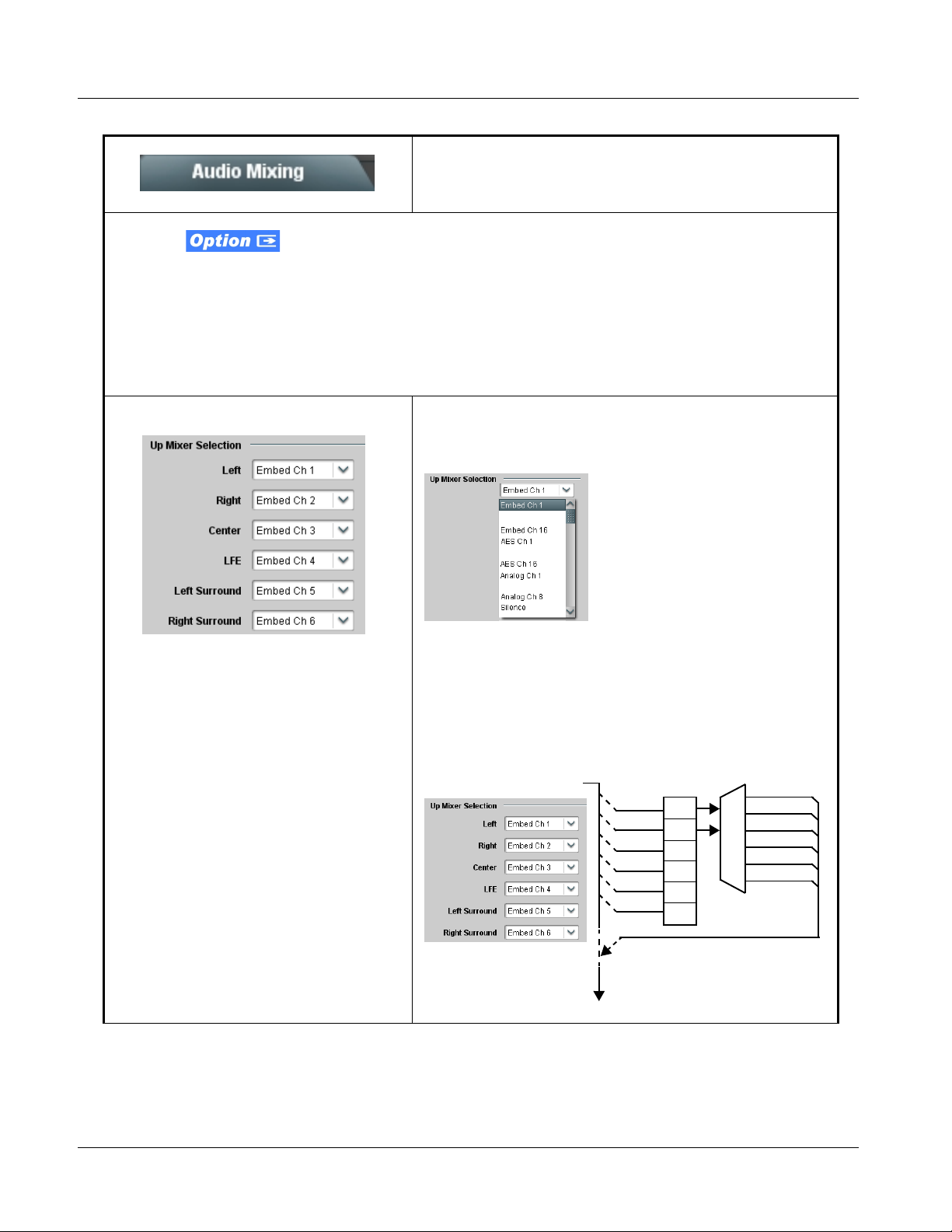
3 9061 Function Submenu List and Descriptions
Table 3-2 9061 Function Submenu List — continued
(continued)
Note: • 2.0-to-5.1 upmixer function is an optional licensable feature. This function and its controls appear only when a license
key is entered and activated. Refer to Licensable Features function description on page 3-55 for mor e information.
• Channel sources used by the upmixer are post-processed signals received from the Audio Routing/Gain Control
function. When active, the channel selections made using this function are directly embedded in the output SDI or
AES discrete pairs. Refer to 2.0-to-5.1 Upmix Function (p. 1-15) in Chapter 1, “Introduction” for detailed functional
description and signal flow.
• For any six channels selected for this function, the Left and Right channel selections always serve as the stereo input
pair.
• 2.0-to-5.1 Up Mixer Selection Separate drop-down lists for Left, Right, Center, LFE, Left Surround,
and Right Surround allow embedded, AES, or analog channel audio
source selection, and embedded or AES discrete channel assignments
for the six generated 5.1 channels.
•
•
•
•
•
•
•
•
•
The example below shows selection of embedded channels 1 and 2 as
the received stereo source (Embed Ch1 and Ch 2 for Left and Right
drop-down list selections in the Up Mixer Selection tool).
Using the setup shown in the example, when upmix is active the
embedded channel 1/2 stereo pair is overwritten with the new stereo pair
L/R on channels 1/2. As selected in the example, the additional 5.1
channels C, LFE, Left Surround (Ls), and Right Surround (Rs) overwrite
Emb Ch 3 – Ch 6, respectively.
Emb Ch 1 –
Ch 16
>
Emb Ch 1
Emb Ch 2
Emb Ch 3
Emb Ch 4
Emb Ch 5
Emb Ch 6
L
R
(C)
(LFE)
(Ls)
(Rs)
L – Emb Ch 1
R – Emb Ch 2
C – Emb Ch 3
LFE – Emb Ch 4
Ls – Emb Ch 5
Rs – Emb Ch 6
3-52 9061 PRODUCT MANUAL 9061-OM (V4.9)
Page 97
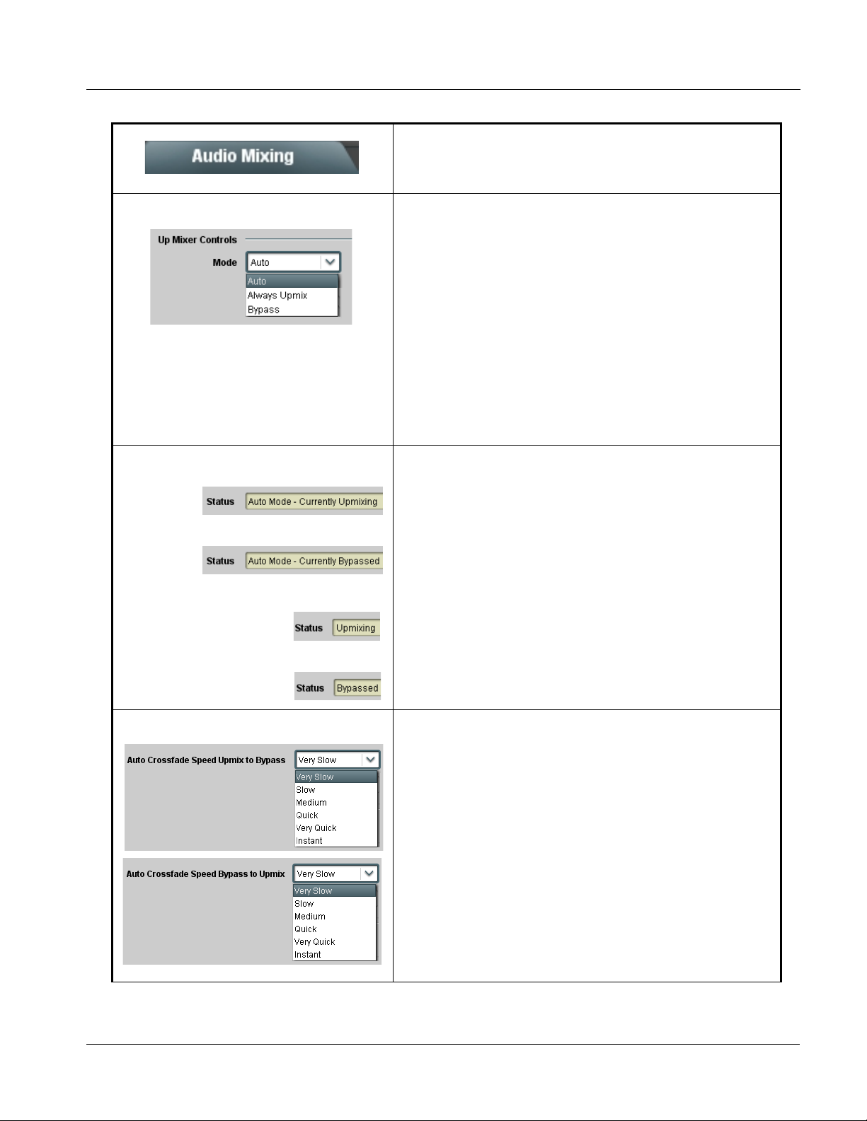
Operating Instructions 9061 Function Submenu List and Descriptions
Table 3-2 9061 Function Submenu List — continued
(continued)
• Up Mixer Mode Control Enables or bypasses upmixer as follows:
• Auto: Automatic enable/bypass of 5.1 upmix function as follows:
• If detected signal level on all four of the selected channels
designated as Center, LFE, Left Surround, and Right Surround
are below the level threshold set using the 5.1 Detection Threshold
control, upmixer overwrites all six selected channels with the new 5.1
content generated by the upmixer.
• If detected signal level on any of the four of the selected channels
designated as Center, LFE, Left Surround, and Right Surround is
above the level threshold set using the 5.1 Detection Threshold
control, upmixer is bypassed and the original channels pass
unaffected.
• Always Upmix: Manual enable turns on upmixer and overwrites content
on all six selected channels with new 5.1 content generated by the
upmixer regardless of original signal level or content.
• Bypass: Manual disable bypasses the upmixer. When bypassed, the six
embedded audio channels pass unaffected.
• Up Mixer Status Display Shows activity status of upmixer processing as follows:
• Auto Mode - Currently Upmixing: With upmixer enable set to
Auto, indicates selected channels designated as Center, LFE, Left
Surround, and Right Surround are clear for use (as described
above); upmixer is currently up-mixing received stereo pair and
overwriting the six selected channels with new 5.1 upmix.
• Auto Mode - Currently Bypassed: With upmixer enable set to
Auto, indicates selected channels designated as Center, LFE, Left
Surround, and Right Surround have content (such as existing
original 5.1 or other content); upmixer is bypassed (disabled) and
allows normal passage of six selected channels.
• Upmixing: Indicates upmixer is manually enabled (set to Always
Upmix) and is currently up-mixing received stereo pair and
overwriting the six selected channels with new 5.1 upmix.
• Bypassed: Indicates upmixer is manually disabled (set to Bypass)
and is currently passing all selected channels unaffected.
• Auto Crossfade Speed Controls Individual controls select the relative crossfade transition speed between
9061-OM (V4.9) 9061 PRODUCT MANUAL 3-53
Upmix to Bypass (going to inactive; from 5.1 to 2.0) and Bypass to Upmix
(going to active; from 2.0 to 5.1) when upmixer enable is set to Auto and
the active threshold (as set by the 5.1 Detection Threshold control) is
crossed in either direction.
To suit program material and production aesthetic preferences, several
choices are available as shown to the left. Slower settings allow for a
more gradual transition between modes, however with a longer interval
before levels stabilize. Faster settings conversely allow for a smaller
interval before levels stabilize, however with greater perceived
abruptness.
Page 98
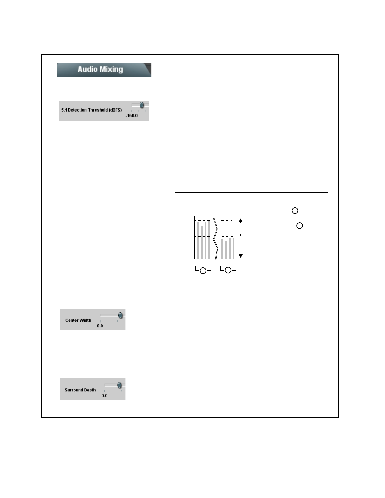
3 9061 Function Submenu List and Descriptions
Table 3-2 9061 Function Submenu List — continued
(continued)
• 5.1 Detection Threshold Control Adjusts the threshold at which selected channels designated as C, LFE,
Ls, and Rs are considered to have viable content, or at which signal levels
can be considered insignificant when upmixer enable is set to Auto.
Setting affects automatic enable/bypass of 5.1 upmix function as follows:
• I f detected signal level on all four of the selected channels designated
as Center, LFE, Left Surround, and Right Surround are below the level
threshold set using the 5.1 Detection Threshold control, upmixer allows
overwrite of all six selected channels with the new 5.1 signal
complement.
• I f detected signal level on any of the four of the selected channels
designated as Center, LFE, Left Surround, and Right Surround is above
the level threshold set using the 5.1 Detection Threshold control,
upmixer is bypassed, thereby releasing the selected six channels and
allowing the original channels to pass unaffected.
(Range is -150 dB to 0 dB in 0.1dB steps;
0 dB equivalent to +24 dBu=> 0 dBFS)
Typically, the 5.1 Detection Threshold control should be set to provide
a usable threshold that maintains a threshold at which valid levels large
enough over the threshold disable the auto upmix ( , left), while
- 20 dBFS
- 60 dBFS
s
s
E
C
L
R
F
L
A
E
C
L
F
L
B
Above Threshold
(Bypass)
Below Threshold
(Overwrite)
s
s
R
nuisance levels
considerably below the
threshold ( , left) are
rejected, allowing the
upmixer to stay locked in
the enabled mode and
overwrite these signals
with the new signals.
Optimum setting is
dependent on program
material general overall
levels. A -60 dB setting is
A
B
recommended for material closely adhering to the SMPTE -20 dBFS
Alignment level for normal material such as dialog.
• Center Width Control
Adjusts center channel content (in terms of percentage) applied to L and
R channels.
• Minimum setting keeps all L+R (mono) content confined to center (C)
channel, with any center channel content removed from L and R
channels.
• Higher settings progressively blend respective L and R mono content
back into L and R channels, with 100% setting resulting in center
channel level going to zero and L/R channels becoming normal L/R
channels containing some mono content.
(0% to 100% range in 0.1% steps; default = 0%)
• Surround Depth Control
Adjusts surround channel content (in terms of percentage) applied to Ls
and Rs channels.
• M aximum setting results in greatest surround channel levels.
• Lower settings progressively diminish surround channel levels, with 0%
setting resulting in no Ls or Rs level, with Ls and Rs content
progressively folded back into L and R, respectively.
(0% to 100% range in 0.1% steps; default = 100%)
3-54 9061 PRODUCT MANUAL 9061-OM (V4.9)
Page 99
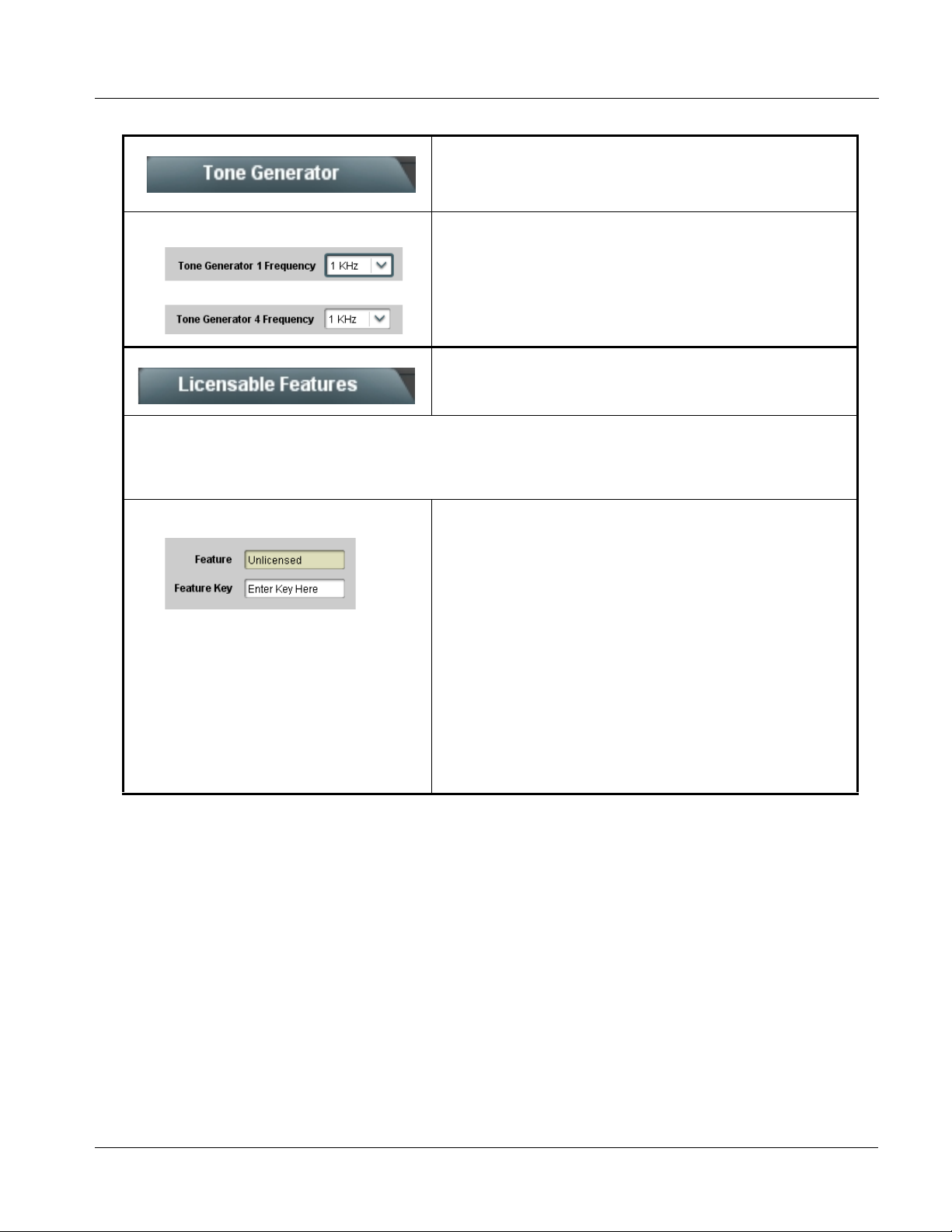
Operating Instructions 9061 Function Submenu List and Descriptions
Table 3-2 9061 Function Submenu List — continued
Sets the test tone frequency for each of four tone
Tone Generator
generators (T one Generator 1 thru 4).
• Frequency Selection Lists Selects the frequency for each of the four tone generators. 18 discrete
•
•
•
Licensable Features
sine wave frequencies are available, ranging from 50 Hz to 16 kHz
(default frequency is 1.0 kHz).
Note: Unity-gain signal level is equivalent to -20 dBu.
Allows activation of optional licensed features.
Note: For card pre-ordered with licensed feature(s), the activation steps described below are not required; the feature will
already be installed activated. To order features and obtain a license key, contact Cobalt
sales@cobaltdigital.com or at the contact information in Contact Cobalt Digital Inc. in Chapter 1, “Introduction”. Please
provide the “SSN” number of your card (displayed in the Card Info pane) when contacting us for your key.
• License Feature and Key Entry window Activate licensable feature as described below.
1. Enter the feature key string in the F eature Key box. Press return or
click outside of the box to acknowledge entry.
Note: Entry string is case sensitive. Do not enter any spaces.
2. In the DashBoard™ Card Info pane, wait for the feature identification to
be shown for the card product number (for example, “-UM” appearing
after the card part number) and V a lid Key Entered to be displayed.
This indicates the key was correctly entered and recognized by the
card.
Note: If DashBoard™ card function submenu/control pane does not
re-appear, close the card and re-open it.
3. Click and confirm Reboot. When the card function submenu/control
pane appears again, the licensable feature will be available.
Note: Applying the licensable feature and its reboot has no effect on
prior settings. All control settings and drop-down selections are
retained.
®
sales at
9061-OM (V4.9) 9061 PRODUCT MANUAL 3-55
Page 100

3 9061 Function Submenu List and Descriptions
Table 3-2 9061 Function Submenu List — continued
Allows up to 16 card user set tin gs co nfi gur at ion pres et s
to be saved in a Preset and then recalled (loaded) as
Presets
desired. All current settings (including list selections
and scalar (numeric) control settings such as Gain, etc.)
are saved when a Preset Save is invoked.
The Preset Name field and Preset Save button
allow custom user setting configurations to be
labeled and saved to a Preset for future use.
The Preset Load button and the Selected Preset
drop-down list allow saved presets to be selected
and loaded as desired. When a preset is loaded, it
immediately becomes active with all user settings
now automatically set as directed by the preset.
Saved presets can be uploaded to a computer for
use with other same-model COMPASS® cards.
Each of the items to the left are described in detail on
the following pages.
• Preset Save and Load • Preset Save stores all current card control settings to the currently
• Selected Preset Selected Preset 1 thru Selected Preset 16 range in drop-down list
•
•
•
selected preset.
(For example, if Preset 1 is selected in the Selected Preset drop-down
list, clicking and confirming Preset Save will then save all current card
control settings to Preset 1)
• Preset Load loads (applies) all card control settings defined by
whatever preset (Preset 1 thru Preset 16) is currently selected in the
Selected Preset drop-down list.
(For example, if Preset 3 is selected in the Selected Preset drop-down
list, clicking and confirming Preset Load will then apply all card control
settings defined in Preset 3)
The above buttons have a Confirm? pop-up that appears, requesting
confirmation.
Note: Applying a change to a preset using the buttons described above
rewrites the previous preset contents with the invoked contents.
Make certain change is desired before confirming preset change.
selects one of 16 stored presets as ready for Save (being written to) or for
Load (being applied to the card).
Note: The preset names shown to the left are the default (unnamed)
preset names. All 16 presets in this case are loaded identically with
the factory default settings.
• Card Name Text entry field provides for optional entry of card name, function, etc. (as
shown in this example).
Note: Card name can be 31 ASCII characters maximum.
3-56 9061 PRODUCT MANUAL 9061-OM (V4.9)
 Loading...