

Page 1

9931-EMDE
3G/HD/SD-SDI
Embedder/De-Embedder
Product Manual
Cobalt Digital Inc.
2406 E. University Ave.
Urbana, IL 61802
Voice 217.344.1243 • Fax 217.344.1245
www.cobaltdigital.com
9931-EMDE-OM (V1.15)
Page 2

Copyright
©Copyright 2014, Cobalt Digital Inc. All Rights Reserved.
Duplication or distribution of this manual and any information contained within is strictly prohibited without the express written
permission of Coba lt Digital Inc. This manual and a ny information contained within, may not be re produced, distribute d, or
transmitted in any form, or by any means, for any purpose, without the express written permission of Cobalt Digital Inc.
Reproduction or reverse engineering of software used in this device is prohibited.
Disclaimer
The information in this document has been carefully examined and is believed to be entirely reliable. However, no responsibility
is assumed for inaccuracies. Furthermore, C obalt Digit al Inc. res erves the right to ma ke changes to any pro ducts herein to improve
readability, function, or design. Cobalt Digital Inc. does not assume any liability arising out of the application or use of any
product or circuit described herein.
Trademark Information
Cobalt® is a registered trademark of Cobalt Digital Inc.
FUSION3G
openGear
encoder technology on this card is manufa cture d unde r licens e from Dol by Labo rat ories. Dolby
Dolby Laboratories, Inc. Other produ ct nam es or tr adema rks ap peari ng in thi s manua l are the property of t heir re spect ive ow ners.
Linear Acoust ic
licensed feature uses the AutoMAX-II™ upmix algorithm provided under license from Linear Acoustic Inc. Loudness processor
licensed feature uses AEROMAX
symbol, AutoMAX, and AutoMAX-II are trademarks of Linear Acoustic Inc. All Rights Reserved.
®
and COMPASS® are registered trademarks of Cobalt Digital Inc.
®
is a registered trademark of Ross Video Limited. DashBoard™ is a trademark of Ross Video Limited. Dolby®
®
, AEROMAX®, and UPMAX® are registered trademarks of Linear Acoustic, Inc. 2.0-to-5.1 audio upmixer
®
algorithms provided under license from Linear Acoustic Inc. Linear Acoustic, the "LA"
®
is a registered trademark of
Congratulations on choosing the Cobalt
part of a full line of modular processing and conversion gear for broadcast TV environments. The Cobalt Digital Inc.
line includes video decoders and encoders, audio embedders and de-embedders, distribution amplifiers, format
converters, remote control systems and much more. Should you have questions pertaining to the installation or
operation of your 9931-EMDE, ple ase cont act us at the cont act info rmat ion on t he front cove r.
®
9931-EMDE 3G/HD/SD-SDI Embedd er/De-Embedder. The 9931-EMDE is
Manual No.: 9931-EMDE-OM
Document Version: V1.15
Release Date: January 27, 2014
Applicable for card
7039
firmware version:
(or greater)
Description of
product/manual
changes:
- Revise manual to reflect product functional changes of latest firmware
release. Refer to Support > Firmware Downloads link at
www.cobaltdigital.com for latest firmware and corresponding functional
description changes and additions.
- Include additional Troubleshooting information.
9931-EMDE-OM (V1.15)
Page 3

Table of Contents
Chapter 1 Introduction . . . . . . . . . . . . . . . . . . . . . . . . . . . . . . . . . . . . . . . . . . . 1-1
Overview ................................................................................................................ 1-1
9931-EMDE Card Software Versions and this Manual ......................................... 1-2
Cobalt Reference Guides........................................................................................ 1-2
Manual Conventions............................................................................................... 1-3
Warnings, Cautions, and Notes .................................................................. 1-3
Labeling Symbol Definitions...................................................................... 1-4
Safety Summary ..................................................................................................... 1-4
Warnings..................................................................................................... 1-4
Cautions...................................................................................................... 1-4
9931-EMDE Base Model and Options................................................................... 1-5
9931-EMDE Functional Description...................................................................... 1-6
9931-EMDE Video/Audio Signal Types.................................................... 1-6
9931-EMDE Video and Audio Options ..................................................... 1-7
Video Subsystem Description .................................................................... 1-8
Audio Subsection Description.................................................................. 1-13
Control and Data Input/Output Interfaces ................................................ 1-21
User Control Interface .............................................................................. 1-22
9931-EMDE Rear Modules...................................................................... 1-24
Audio and Video Formats Supported by the 9931-EMDE....................... 1-26
Technical Specifications....................................................................................... 1-26
Warranty and Service Information ....................................................................... 1-31
Cobalt Digital Inc. Limited Warranty....................................................... 1-31
Contact Cobalt Digital Inc.................................................................................... 1-32
Chapter 2 Installation and Setup . . . . . . . . . . . . . . . . . . . . . . . . . . . . . . . . . . . 2-1
Overview ................................................................................................................ 2-1
Setting I/O Switches for Analog Audio (1-8) Ports ............................................... 2-1
Installing the 9931-EMDE Into a Frame Slot......................................................... 2-2
Installing a Rear Module ........................................................................................ 2-4
9931-EMDE Rear Modules........................................................................ 2-7
Connecting To Phoenix Terminal Connectors ..................................................... 2-15
Setting Up 9931-EMDE Network Remote Control.............................................. 2-15
9931-EMDE-OM (V1.15) 9931-EMDE PRODUCT MANUAL i
Page 4

Chapter 3 Operating Instructions . . . . . . . . . . . . . . . . . . . . . . . . . . . . . . . . . . . 3-1
Overview................................................................................................................. 3-1
Control and Display Descriptions........................................................................... 3-1
Function Submenu/Parameter Submenu Overview .................................... 3-2
9931-EMDE Card Edge Controls, Indicators, and Display........................ 3-3
DashBoard™ User Interface ....................................................................... 3-4
Cobalt® Remote Control Panel User Interfaces .......................................... 3-5
Accessing the 9931-EMDE Card via Remote Control............................................ 3-6
Accessing the 9931-EMDE Card Using DashBoard™............................... 3-6
®
Accessing the 9931-EMDE Card Using a Cobalt
Control Panel............................................................................................. 3-7
Checking Card Information..................................................................................... 3-8
Ancillary Data Line Number Locations and Ranges .............................................. 3-9
9931-EMDE Function Submenu List and Descriptions........................................ 3-10
Video Proc/Color Correction ................................................................... 3-11
Timecode .................................................................................................. 3-15
Closed Captioning .................................................................................... 3-19
Framesync ................................................................................................ 3-20
AFD/WSS/VI ARC Controls ................................................................... 3-23
Video Output Crosspoint Control ............................................................ 3-29
Input Audio Status .................................................................................... 3-30
Audio Bus Input Routing/Controls .......................................................... 3-31
Output Audio Routing/Controls ............................................................... 3-41
Upmixing .................................................................................................. 3-46
COM and Metadata Routing .................................................................... 3-49
GPIO Controls .......................................................................................... 3-51
Presets ...................................................................................................... 3-53
Event Based Preset Loading ..................................................................... 3-54
Audio Routing with GPI Control Example............................................... 3-57
Troubleshooting .................................................................................................... 3-62
Remote
Error and Failure Indicator Overview....................................................... 3-62
Basic Troubleshooting Checks.................................................................. 3-66
9931-EMDE Processing Error Troubleshooting....................................... 3-66
Troubleshooting Network/Remote Control Errors.................................... 3-69
What To Do If Your Card Locks Up......................................................... 3-69
In Case of Problems .................................................................................. 3-70
ii 9931-EMDE PRODUCT MANUAL 9931-EMDE-OM (V1.15)
Page 5

Overview
Chapter 1
Chapter 1 Introduction
This manual provides installati on and o per at ing instr uct ions for the
9931-EMDE 3G/HD/SD-SDI Embedder/De-Embedder card (also referred to
herein as the 9931-EMDE).
Note: This manual is also applicable for reduced functionality versions:
• 9931-DE (De-embed only)
• 9931-EM (Embed only)
In all other facets, the three cards function identically. (The 9931-DE and
9931-EM can be field-upgraded to full 9931-EMDE functionality using a software upgrade which is performed without removing the card from its frame.)
This manual consists of the following chapters:
• Chapter 1, “Introduction” – Provid es informa tion about this manual
and what is covered. Als o pr ovi des general information re gar di ng the
9931-EMDE.
• Chapter 2, “Installation and Setup” – Provides instructions for
installing the 9931-EMDE in a frame, and optionally installing
9931-EMDE Rear Modules.
• Chapter 3, “Operating Instructions” – Provides overviews of
operating controls and instructions for using the 9931-EMDE.
This chapter contains the following information:
• 9931-EMDE Card Software Versions and this Manual (p. 1-2)
• Manual Conventions (p. 1-3)
• Safety Summary (p. 1-4)
• 9931-EMDE Base Model and Options (p. 1-5)
• 9931-EMDE Functional Description (p. 1-6)
• Technical Spe cification s (p. 1-26)
• Warranty and Service Information (p. 1-31)
• Contact Cobalt Digital Inc. ( p. 1-32)
9931-E MDE-O M (V1.15) 9931-EMDE PRODUCT MANUAL 1-1
Page 6

1 9931-EMDE Card Software Versions and this Manual
9931-EMDE Card Software Versions and this Manual
When applicable, Cobalt Digital Inc. provides for continual product
enhancements through software updates. As such, functions described in this
manual may pertain specifically to cards loaded with a particular software
build. Cards loaded with initial software builds may not reflect all
functionality described in “9931-EMDE Functional Description” of this
chapter. Also note that some functions described here are options, and
may not appear on all 9931 cards.
The Software Version of your card can be checked by viewing the Ca r d I n fo
menu in DashBoard™. See Checking Car d I nfo rmat ion (p. 3-8) in Chapter 3,
“Operating Instructi ons” for mor e information. You can then ch eck our
website for the latest software version currently released for the card as
described below.
Check our website and proceed as follows if your card’s software does not
match the latest versi on:
Card Software earlier than
latest version
Card Software newer than
version in manual
Card is not loaded with the latest software. Not all
functions and/or specified performance described in
this manual may be available.
You can update your card with the new Update
software by going to the Support>Firmware
Download link at www.cobalt digital.com. Download
“Firmware Update Guide”, which provides simple
instructions for downloading the latest firmware for
your card onto your computer, and then uploading it
to your card through DashBoard™.
Software updates are field-installed without any
need to remove the card from its frame.
A new manual is expediently released whenever a
card’s software is updated and specifications
and/or functionality have changed as compared
to an earlier version (a new manual is not
necessarily released if specifications and/or
functionality have not changed). A manual earlier
than a card’s software version may not completely
or accurately describe all functions available for
your card.
If your card shows features not described in this
manual, you can check for the latest manual (if
applicable) and download it by going to the
Support>Documents>Product Information and
Manuals link at www.cobaltdigital.com.
Cobalt Reference Guides
From the Cobalt® web home page, go to Support>Documents>Reference
Guides
updates, and other topics.
1-2 9931-EMDE PRODUCT MANUAL 9931-EMDE-OM (V1.15)
for easy to use guide s covering network remot e control , card fir mware
Page 7

Introduction Manual Conventions
Manual Conventions
In this manual, display messages and connectors are shown using the exact
name shown on the 9931-EMDE itself. Examples are provided below.
• Card-edge display messages are shown like this:
Ch01
• Connector and control names are shown like this: AES I/O 8
In this manual, the terms below are applicable as follows:
• 9931-EMDE refers to the 9931-EMDE 3G/HD/SD-SDI Embedder/
De-Embedder card.
• Frame refers to the 20-slot frame that houses the Cobalt
COMPASS
• Device and/or Card refers to a COMPASS
®
and/or FUSION3G® cards.
®
and/or FUSION3G®
card.
®
Warnings, Cautions, and Notes
Certain items in this manual are highlighted by special messages. The
definitions are provided bel ow.
Warnings
Warning messages indicate a possible hazard which, if not avoided, could
result in pe rsonal injury or death.
Cautions
• System and/or Video System refers to the mix of interconnected
production and terminal equipment in which the 9931-EMDE and
other COMPASS
• Functions and/or features that are available only as an option are
®
and/or FUSION3G® cards operate.
denoted in th is manual like this:
Not all options are covered in this manual. In these cases, Manual
Supplement(s) for the option(s) ordered have been included in the
binder containing this manual.
Caution messages indicate a problem or incorrect practice which, if not
avoided, could result in improper operation or damage to the product.
Notes
Notes provide supplemental information to the accompanying text. Notes
typically precede the text to which they apply.
9931-EMDE-OM (V1.15) 9931-EMDE PRODUCT MANUAL 1-3
Page 8
1 Safety Summary
Labeling Symbol Definitions
Attention, consult accompanying documents.
Electronic device or as sembly is susceptible to damage from an ESD event.
Handle only using appropriate ESD prevention practices.
If ESD wrist strap is not available, handle card only by edges and avoid contact
with any connectors or components.
Symbol (WEEE 2002/96/EC)
For product disposal, ensure the following:
• Do not dispose of this product as unsorted municipal waste.
• Collect this product separately.
• Use collection and return systems available to you.
Safety Summary
Warnings
! WARNING !
! WARNING !
Cautions
CAUTION
CAUTION
CAUTION
T o redu ce risk of electr ic shock do not remove line voltage service barrier cover on frame
equipment containing an AC power supply. NO USER SERVICEABLE PARTS INSIDE.
REFER SERVICING TO QUALIFIED SERVICE PERSONNEL.
Adhere to GPO port maximum voltage/current limits. This port is specified for
low-voltage/low-current control circuits only. Using this port for any other purpose may
result in an unsafe condition and can damage the card.
CLASS 1 LASER PRODUCT - IEC 60825-1:2007. Never look into fiber connector or cable
end of device transmitting an optical signal. The transmitted light is not visible and can
cause permanent eye damage. Do not perform connection/disconnection with sending or
receiving device powered.
This device is intended for environmentally controlled use only in appropriate video
terminal equipment operating environments.
This product is intended to be a component product of an openGear® frame. Refer to the
openGear® frame Owner's Manual for important safety instructions regarding the proper
installation and safe operation of the frame as well as its component products.
Heat and power distribution requirements within a frame may dictate specific slot
placement of cards. Cards with many heat-producing components should be arranged to
avoid areas of excess heat build-up, particularly in frames using only convection cooling.
The 9931-EMDE has a moderate power dissipation (20 W max.). As such, avoiding placing
the card adjacent to other cards with similar dissipation values if possible.
CAUTION
CAUTION
If required, make certain Rear Module(s) is installed before installing the 9931-EMDE into
the frame slot. Damage to card and/or Rear Module can occur if module installation is
attempted with card already installed in slot.
If card resists fully engaging in Rear Module mating connector, check for alignment and
proper insertion in slot tracks. Damage to card and/or Rear Module may occur if improper
card insertion is attempted.
1-4 9931-EMDE PRODUCT MANUAL 9931-EMDE-OM (V1.15)
Page 9
Introduction 9931-EMDE Base Model and Options
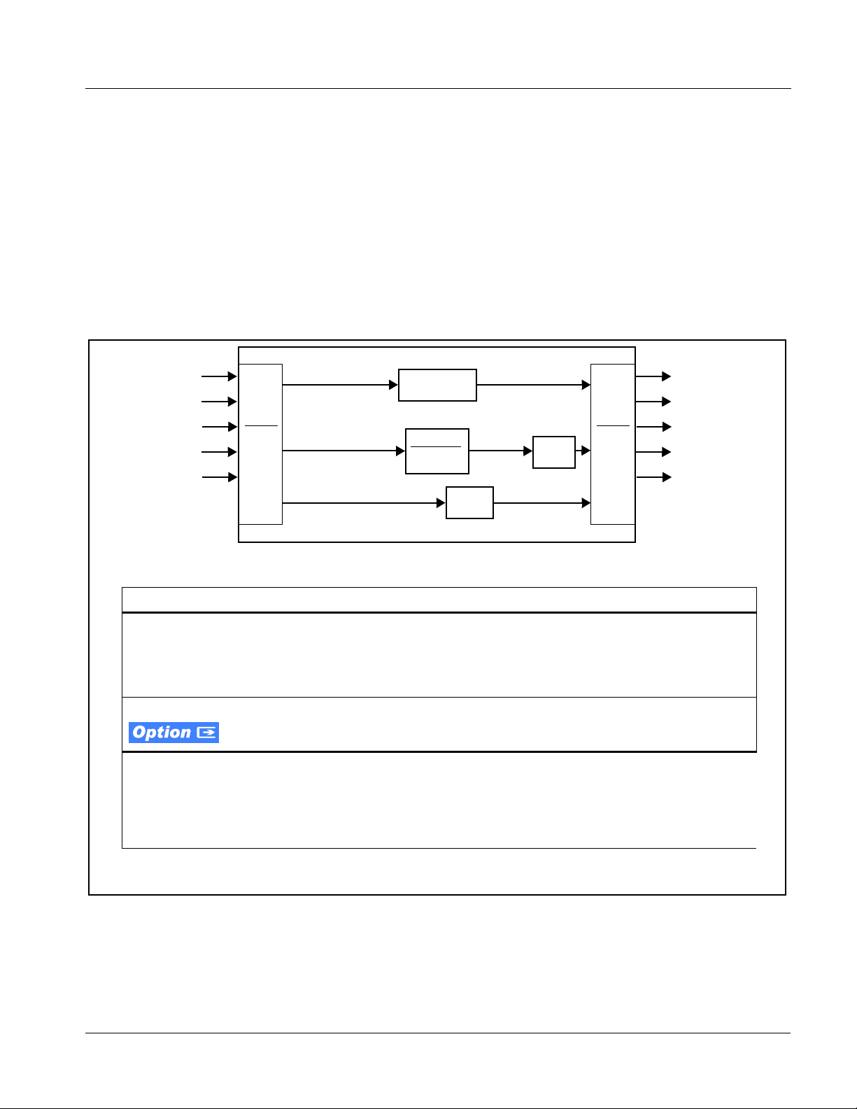
9931-EMDE Base Model and Options
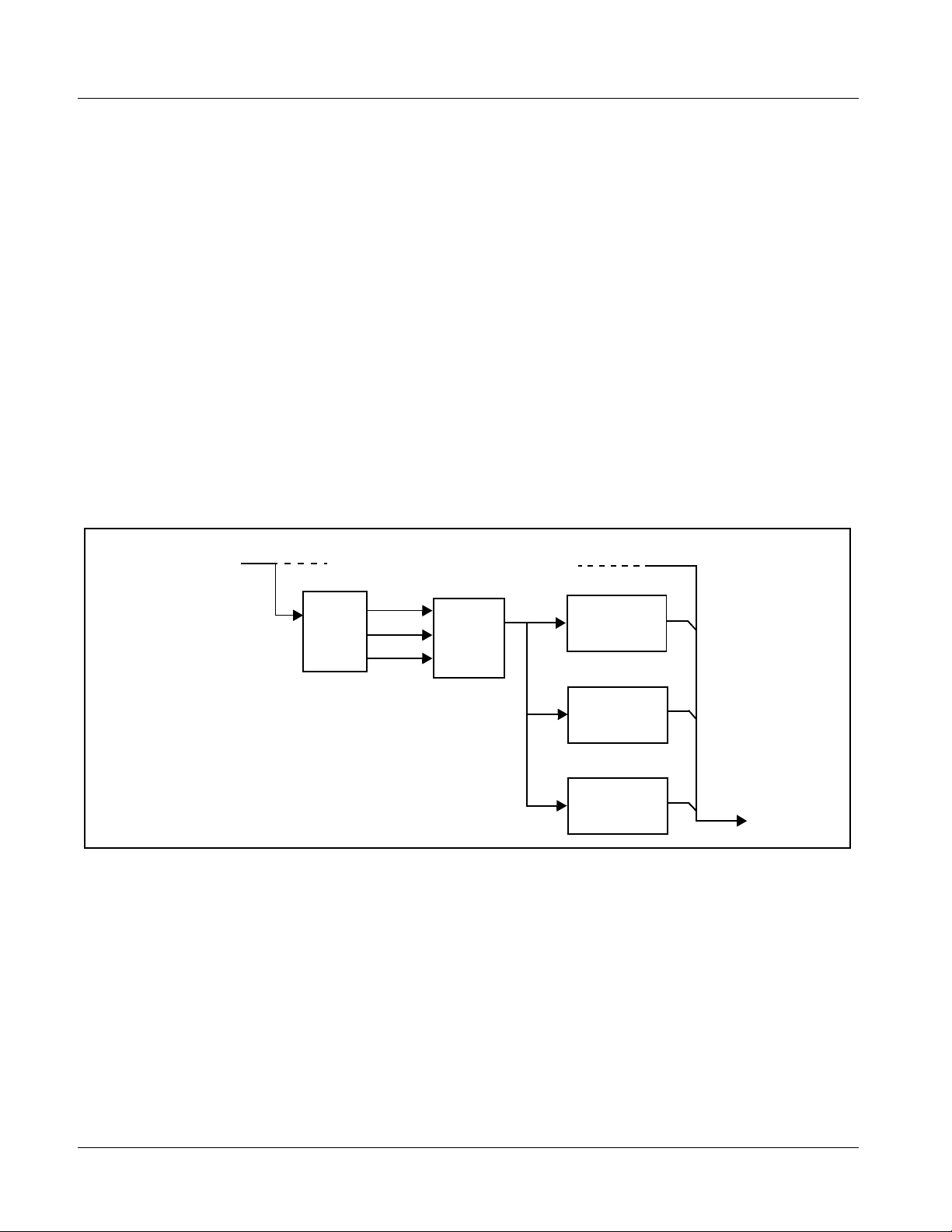
(See Figure 1-1.) The base model 9931-EMDE provides video processing,
embedded and discrete audio support, and timecode/closed captioning
support. Options add various I/O, video, and audio expanded capabilities to
the base model as shown in Figure 1-1 and described below. The various
options are describe d in detail in 9931-EMDE Video and Audio Options (p.
1-7), and as applicable throughout this manual.
As such, the 9931-EMDE is highl y sui te d as a un iv ers al processing card with
comprehensive audio and video support for environments requiring legacy,
current, and advanced platform support.
3G/HD/SD-SDI (BNC)
3G/HD/SD Fiber*
AES Audio
Analog Audio*
Analog Video*
Base Features/Functions
• 3G/HD/SD-SDI coax (BNC) input/
output
• Advanced audio processing with
full routing, gain, and delay control
• Video Proc controls
Option Features/Functions
• 3G/HD/SD-SDI Fiber input/output.
Blind mate interface allows card
swapping with no cable
disconnection.
• Linear Acoustic® loudness
processing and automatic upm ixin g
Input
Video
Routing
Audio
Mux/
De-mux/
Routing
* denotes option
• Per-channel audio-video delay
control
• AES ports GUI-selectable as input
or output. Independent SRCs for
each input.
• Universal HD/SD analog video
input. 3D comb decoder on analog
video input. Composite video
output is color-framed to match
reference burst, plus user offset.
• Frame sync with reference
selectable from multiple sources
VANC Data
Video Proc
Correction*
16-Channel Internal Audio Bus
Controls
Color
Audio
Proc
• SMPTE timecode support, with
translation across formats
• Analog audio inp uts and outpu ts.
Full 24-bit conversion.
• Complete Dolby
and decoder options
®
Frame
Sync*
E / AC-3 encoder
3G/HD/SD-SDI (BNC)
Output
Video
Routing
Audio
Mux/
De-mux/
Routing
• GPI ports with user-definable
functions
• Centralized GUI remote control
using DashBoard™ softwa re and
Cobalt OGCP-9000 Remote
Control Panels
3G/HD/SD Fiber*
AES Audio
Analog Audio*
Analog Video*
Figure 1-1 9931-EMDE Simplified Overview of Base and Option Features/Functions
9931-EMDE-OM (V1.15) 9931-EMDE PRODUCT MANUAL 1-5
Page 10

1 9931-EMDE Functional Description
9931-EMDE Functional Description
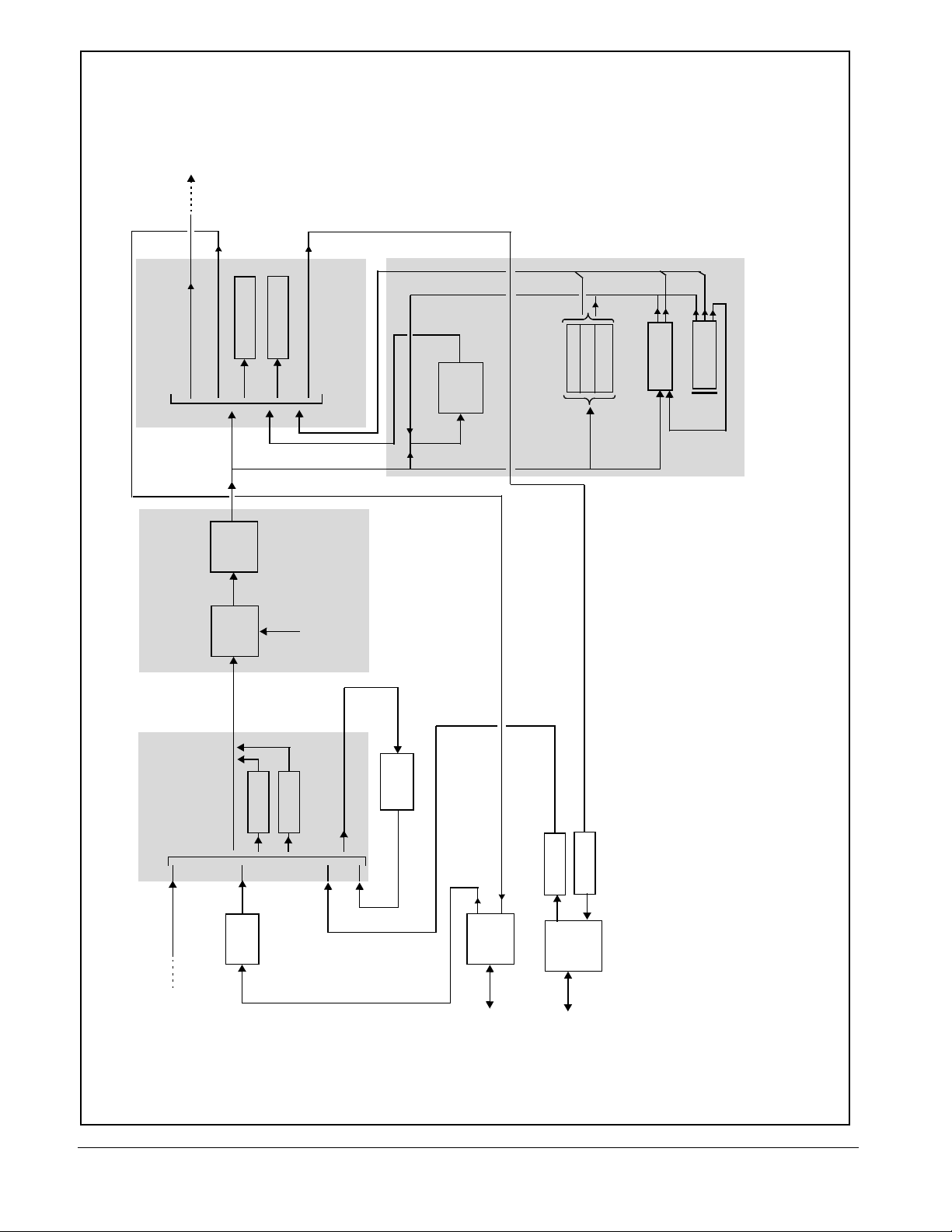
Figures 1-2 and 1-5 show functional block diagrams of the 9931-EMDE
video/control and audio subsystems, respectively.
The base 9931-EMDE provides video processing, embedded audio support,
and AFD/timecode/closed-captioning support. Various I/O, video, and audio
options add expanded capabilities to the base model as described below.
9931-EMDE Video/Audio Signal Types
Table 1-1 lists the video/audio inputs and outputs (available via rear module
connections) provided by the 9931-EMDE. Note that some signal types are
supported through the use of options, and also require a rear module that
supports the connections described here; the complete option/rear module
requirement is specified in Table 1-1.
Table 1-1 9931-EMDE Video/Audio Signal Types
Option/Rear Module
Signal ID Description
Package Required
SDI IN A
Fiber Rx-A I/O,
Fiber Rx-B I/O
AES Audio IN/OUT (1-16)
Analog Video/Audio I/O
3G/HD-SD-SDI BNC video input Standard
❑ Various Rear Modules offer various
SDI BNC input complement s. Se e
9931-EMDE Rear Modules (p.
2-7) for more information.
Up to two 3G/HD-SD-SDI fiber LC
video inputs; routable to card
processing via input crosspoint
Eight AES 3-id BNC pairs; each pair
user GUI-selectable as either input
or output.
Up to eight balanced analog audio
channels (using Phoenix™ 3-wire
terminati ons); each channel
switch-selectable as either input or
output.
HD/SD composite and component
analog I/O
• Option +FRx (1 Fiber input)
• Option +FRx/Tx (1 Fiber input; 1
Fiber output)
• Option +FRx/Rx (2 Fiber inputs)
❑ Requires Expansion Rear Module
supporting fiber I/O. See
9931-EMDE Rear Modules (p.
2-7) for more information.
Standard
❑ Various Rear Modules offer various
number of AES pairs supported.
See 9931-EMDE Rear Modules
(p. 2-7) for more information.
Refer to option Manual Supplement
OPT-F3GAN-MS for descriptions of
analog video/audio I/O options
available.
1-6 9931-EMDE PRODUCT MANUAL 9931-EMDE-OM (V1.15)
Page 11

Introduction 9931-EMDE Functional Description
Table 1-1 9931-EMDE Video/Audio Signal Types — continued
Option/Rear Module
Signal ID Description
Package Required
SDI OUT A
Note: The input/output complement listed above and shown in Figures 1-2 and 1-5 represents the maximum capability of the
9931-EMDE. The practical input/output complement is determined by the particular Rear Module used with the 9931-EMDE.
Not all options are available concurrently on a single card.
3G/HD-SD-SDI BNC video output Standard
❑ V arious Rear Modules of fer vario us
SDI BNC output complements.
See 9931-EMDE Rear Modules
(p. 2-7) for more information.
9931-EMDE Video and Audio Options
In addition to the I/O options described in Table 1-1 above, the 9931-EMDE
offers several video and audio options described in Table 1-2. Note that
several options also require a rear I/O option that supports the video and/or
audio options described here; the complete option requirement is specified in
Table 1-2.
Table 1-2 9931-EMDE Video/Audio Options
Option/Rear Module Package
Option Description
Note: Options are perio dically a dded for th is card . Chec k for lat est opti ons on the card web pag e at cob altd igit al.c om. Mo st
options, in addition to licensing, require that card be loaded with the latest available firmware.
Required
Video Options
Color Correction In addition to standard video proc controls,
provides independent RGB channel controls
for luma, black, and gamma.
Audio Options
Linear Acoustic® Loudness
Processing software
OGCP Loudness Meter
software
(Note 1)
Linear Acoustic
software
(Note 2)
®
Upmixing
Automatic Downmixing
Linear Acoustic® AEROMAX® 5.1-channel or
stereo audio output loudness processing;
several combinations available
5.1-channel loudn ess meter i n accordance with
EBU R128, ATSC A/85 and ITU BS.1770.
Allows OGCP-9000 to provide user interface.
Linear Acoustic® AUTOMAX™ converts legacy
stereo program audio (from any source
received by the card) to 5.1-channel audio.
Provides a stereo downmix from selected
alternate multi-channel sources if selected
primary L/R channels lose signal.
• Option +COLOR
• Option +LP51 (5.1-Ch loudness
processing)
• Option +2LP20 (dual independent
stereo loudness processing)
• Option +LP20 (stereo loudness
processing)
• Option +LM
• Option +UM
• Option +ADM
9931-EMDE-OM (V1.15) 9931-EMDE PRODUCT MANUAL 1-7
Page 12

1 9931-EMDE Functional Description
Table 1-2 9931-EMDE Video/Audio Options — continued
Option/Rear Module Package
Option Description
Required
Automatic Audio Failover Provides failover to alternate (“secondary”)
®
Dolby
E/AC-3 Decoding Provides Dolby® E and/or AC-3 decoding from
Dolby® Digital (AC-3),
Digital Plus™ Encoding
®
E Encoding Provides Dolby® E encoding from any audio
Dolby
Notes: 1. This option must be used in conjunction with a Cobalt® OGCP-9000 Remote Control Panel. The control panel serves as the
control/display portal.
2. Option +UM can be used in conjunction with Loudness Processing options.
channels to substitute for the primary channels
in the event of audio signal loss.
embedded and AES sources.
Provides Dolby® AC-3 encoding from any
audio source used by the card (inc luding m ixed
and loudness-processed audio).
Accommodates internally generated and
external metadata.
source used by the card (including mixed and
loudness-processed audio). Accommodates
internally generated and external metadata.
• Option +AFO
• Option +DEC
❑ If serial metadat a R x /Tx su ppo rt is
needed, requires Rear Module
with RS-485 port
• Option +ENCD
❑ If serial metadat a R x /Tx su ppo rt is
needed, requires Rear Module
with RS-485 port
• Option +ENCE
❑ If serial metadat a R x /Tx su ppo rt is
needed, requires Rear Module
with RS-485 port
Video Subsystem Description
Note: Descriptions below include some functions and features that are available
only as options.
Video Processor
The 9931-EMDE provides full color processing control (luma gain and lift,
chroma saturation, and color phase) of the output video. The color correction
option (
black, and gamma. The color correction function converts the YCbCr SDI
input video to the 4:4:4 RGB color space (where the color correction is
applied), and then back to YCbCr SDI on the output of the function. Controls
are available to adjust each RGB level independently for both white levels
(gain) and black levels (offset). Gamma can also be independently adjusted
for each RGB channels. Various controls can be ganged to provide adjustmen t
for all three color channels simultaneously.
+COLOR) provides independent RGB channel controls for luma,
1-8 9931-EMDE PRODUCT MANUAL 9931-EMDE-OM (V1.15)
Page 13
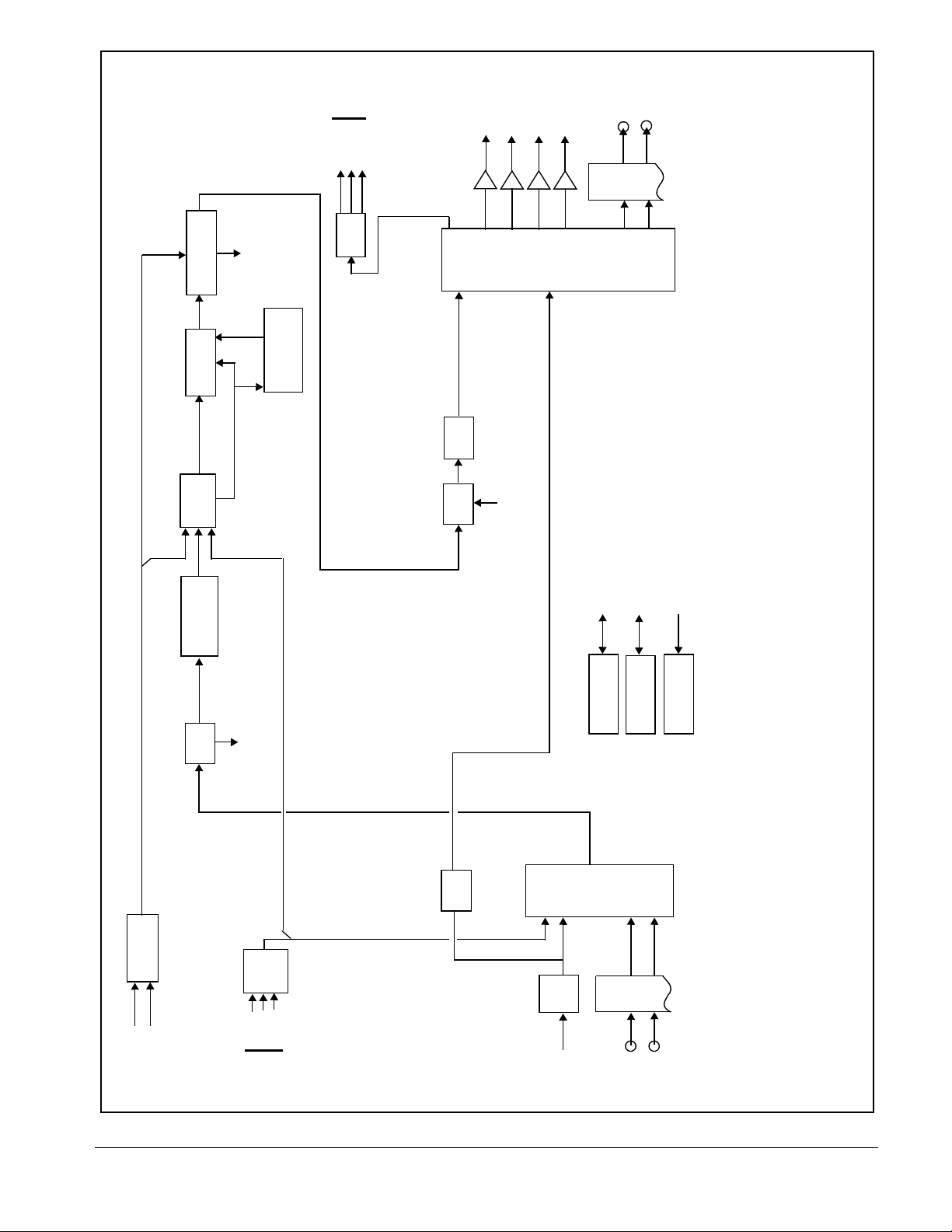
HD/SD
Analog
Video
Y/Cmpst OUT
Pb/C OUT
Video
OUT
SDI OUT A
SDI OUT B
SDI OUT C
SDI OUT D
Pr OUT
Cable
(NOTE 4)
Drivers
FIBER Tx-A OUT
Tx A
Tx
Fiber
DAC
F9931-EMDE_VID4_ 11
FIBER Tx-B OUT
Tx B
Program
ANC
H-V Offset
Video Framesync/
Re-Insert
ANC Control/
to audio subystem
Audio offset control
TC/CC ANC
Data Out
Processors
Timecode and
Closed Captioning
Data In
TC/CC ANC
Crosspoint
Output Video
(NOTE 4)
PROGRAM VIDEO
RCLK INPUT VID
Serialize
Video
ANC
Extract/
Processing
Video Proc/
Color Correction
Audio
Demux
audio subystem
De-embed audio to
Mux
Audio
Audio from audio
subsystem
crosspoint is reserved feature.
Ethernet 10/100 (on fra me)
GPI 1,2
COM 1, 2 (Metadata I/O; RS-485 LTC I/O)
2. Some functional blocks shown are available only as options. Refer to text.
3. Refer to 9931 Audio Block Diagram for audio embed/de-embed/routing audio subsystem.
options package, and card firmware version.
4. Reclocked input video fed to the Output Video Crosspoint is available only from SDI IN A input. Output SDI video
5. Input/output complement shown depicts full capacity. Practical I/O complement is determined by I/O module(s),
Notes: 1. All video input/outputs are 3G/HD/SD-SDI coaxial unless otherwise specified.
Serial Rx/Tx
Interface
GPIO
Control
Network Remote
PGM VID IN
Input
Select
Crosspoint
Deserialize/
EQ
SDI IN A
Rx
Fiber
Rx B
Rx A
FIBER Rx-A IN
FIBER Rx-B IN
Figure 1-2 9931-EMDE Video/Control Block Diagram
Frame Ref
Select/Failover
FRAME REF IN 2
FRAME REF IN 1
Y-channel analog VANC
Reclock
ADC
Video
Filter/
Pr IN
Pb/C IN
Y/Cmpst IN
HD/SD
Analog
Video IN
9931-EMDE-OM (V1.15) 9931-EMDE PRODUCT MANUAL 1-9
Page 14

1 9931-EMDE Functional Description
Frame Sync Function
This function provides for frame sync control using either one of two external
FRAME REF IN (1,2) reference signals distributed with the card frame, or the
input video as a frame sync reference.
This function also allows horizontal and/or vertical offset to be added
between the output video and the frame sync reference.
Frame sync can select from ei ther of two card frame reference sources, input
vdeo, or free-run (internal clock) video sync. Selectable failover allows
alternate reference selection should the init ial reference source become
unavailable or invali d. In the event of input video loss of signal, the output
can be set to disable video, go to black, go to an internal test signal generator
pattern, or freeze to the last intact frame (last frame having valid SAV and
EAV codes).
An internal test signal generator provides a selection of 10 standard patterns
such as color bars, sweep pa tterns, an d other tech nical pat terns. The gen erator
output can be invoked upon loss of program video input, or applied to the
program video output via user controls.
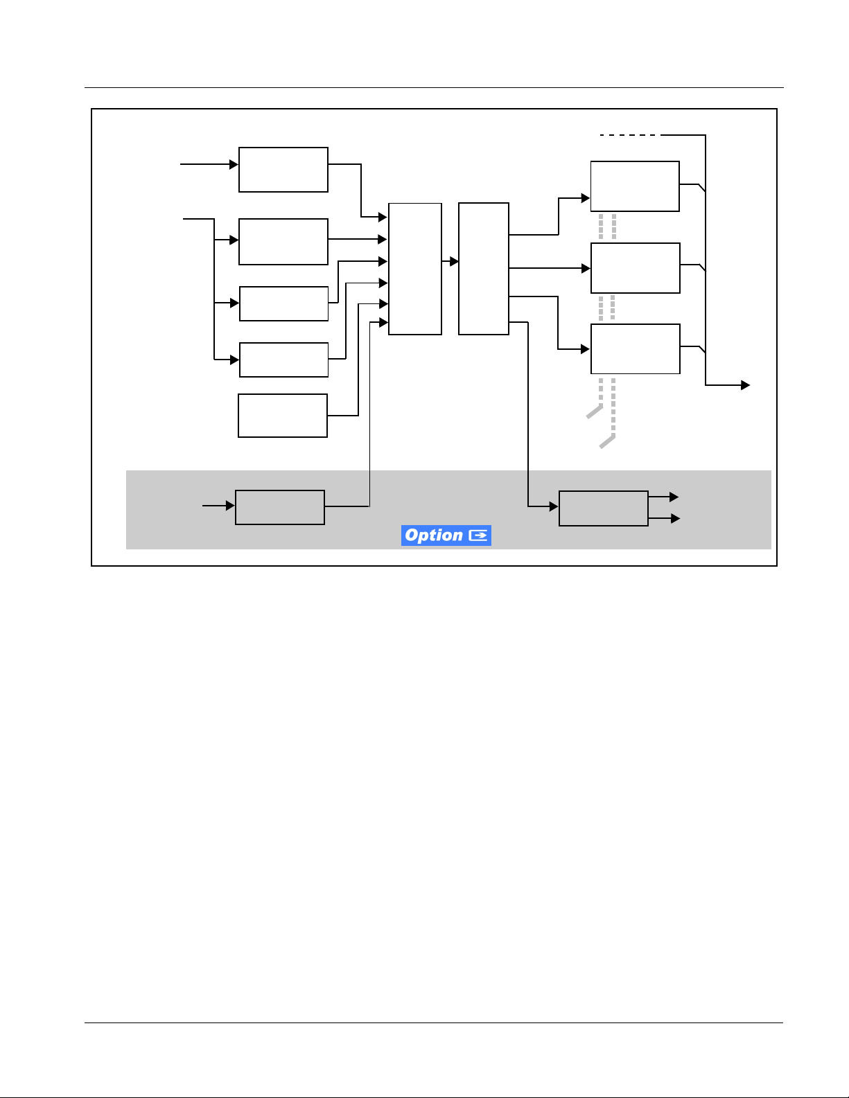
Timecode Processor
(See Figure 1-3.) This function uses extracted ti mecode data from the input
video (waveform or ATC), reference VITC waveform, or internal (free run)
and in turn re-inserts selected timecode data into the program video signal.
The function can monitor video input and reference input for supported
timecode formats, and t hen s el ect and prioritize among SDI VITC waveform,
SDI ATC_VITC, and SDI ATC_LTC timecode sources. If the preferred
format is detected, the preferred format is used by the card; if the preferred
format is not detected, the card uses other formats (where available) as
desired.
The function also provi des conv ersio n bet ween var ious t imecode format s and
provides independent insertion and line number controls for each SDI
timecode output format.
When licensed with option
receive, send and tra nsl at e between audio/RS-485 LTC timecode formats and
the VBI formats described above. Refer to catalog or Fusion3G
supplement OPT-F3GLTC-MS for more information.
+LTC, this function also can
®
manual
1-10 9931-EMDE PRODUCT MANUAL 9931-EMDE-OM (V1.15)
Page 15
Introduction 9931-EMDE Functional Description
3G/HD/SD–SDI
Frame
Reference
Program
Video
Input
Ref VITC
Waveform
Detect/Extract
SDI VITC
Waveform
Detect/Extract
SDI ATC_VITC
Detect/Extract
SDI ATC_LTC
Detect/Extract
Priority/
Select
Buffer/
Format
(From video proc)
SDI VITC
Timecode
Proc/Embed
ATC_VITC
Timecode
Proc/Embed
ATC_LTC
Timecode
Proc/Embed
Audio/
RS-485 LTC
Free Run
(Internal Count)
Audio LTC
Select/Extract
Figure 1-3 Timecode Processor
Insert
Control
Line
Number
Control
Audio/RS-485
LTC Generate
Audio LTC Out
RS-485 LTC Out
9931-EMDE-OM (V1.15) 9931-EMDE PRODUCT MANUAL 1-11
Page 16
1 9931-EMDE Functional Description
ARC Processor
(See Figure 1-3.) This function uses extracted Aspect Ratio Control (ARC)
data from the input video (in either AFD, WSS, or VI formats) and provides:
• Format translation between AFD, WSS, and VI ARC formats.
• H/V cross-conversion matri x in which a re ceived code dire cts a same
or other user-selectable alternate H/V ratio on the output for any of
several H/V ratios.
The input video is checked for ARC formats and can be set to provide a
trigger upon when a selected ARC format is received, the code associated
with the received format can be app lied to the o utput as a translated format
(for, example, fr om WSS to AFD). Received H/V codes can also be applied
through an H/V convers ion mat rix t hat al lo ws alte rnate H/V rat ios f or a gi ven
received input code. The ARC code format priority works in that AFD has
highest priority, with WSS or VI selectable as the next priority. In conjunction
with a user-accessible cross-matrix table, the received code then in turn
directs any of severa l use r -sel ec table H/V set ting s to be ins ert ed on the o utp ut
video as AFD, WSS, and/or VI codes. AFD, WSS and/or VI can be rejected
for input consideration.
Program
Video
Input
Format
Detect/
Select
Note: 1. Line number control available only for AFD
format. WSS and VI use fixed line numbers per
applicable standards.
2. Some AFD codes are not supported in VI and
WSS formats.
Closed Captioning Processor
This function provides support for closed captioning setup. When enabled,
the function allows passage of timecode data. The function also allows the
selection of the ancillary data line number where the ancillary closed caption
data is outputted when the output is HD.
AFD
WSS
VI
Figure 1-4 ARC Processor
Output
ARC
CrossMatrix
AFD Generate/
Insert Control
WSS Generate /
Insert Control
VI Generate/
Insert Control
Program
Video
Output
1-12 9931-EMDE PRODUCT MANUAL 9931-EMDE-OM (V1.15)
Page 17

Introduction 9931-EMDE Functional Description
Audio Subsection Description
Note: Descriptions below include some functions and features that are available
only as options.
(See Figure 1-5.) The 9931-EMDE audio processing subsection is built
around a card internal 16-channel bus. This 16-channel bus receives inputs
from an input routing crosspoint that routes de-embedded and discrete AES
signals over the 16-channel bus. Correspondingly, at the output end of the
16-channel bus is an output routing crosspoint that in turn distributes the
16-channel bus signals to embedded and discrete AES audio outputs.
An Input Audio Status display shows the presence and peak level of each
input audio channel received by the card. For digital audio inputs, payload is
identified (PCM or data such as Do lby
for discrete AES inputs. Disc rete AES inputs can hav e sample rate conve rsion
applied to align these inputs with the output timing (received sample rates
from 32 kHz to 96 kHz are supported).
An Audio DSP function (which interfaces with the output routing block)
provides eight tone generators and advanced functions such as loudness
processing and upmixing . The routi ng and Audio DSP fu nctions are described
in detail later in this section.
®
Digital or E), as well as sample rate
As such, the audio subsecti on provides a full cr osspoint betwee n all supported
audio inputs and output formats.
The audio subsection allows choices from the following audio inputs:
• 16 channels of de-embedded audio from the SDI program video path
• Up to 16 channels (8 pairs) of discrete AES input
• Up to 8 channels of balanced analog audio input
• Up to 10 channels of decoded Dolby
• Digital silence (mute) setting
®
E or AC-3 audio
The audio subsection allows routing to the following audio outputs:
• 16 channels of embedded audio on the SDI output
• Up to 16 channels of discrete AES output on eight AES pairs
• Up to 8 channels of balanced analog audio output
Note: Practical AES channel count handled by the card is 8 pairs, of which each
pair can be user GUI-selectable as an input or output.
All embedded and AES channels have st atus displays that show the fol lowing
for each channel pair:
• PCM signal presence
• Dolby E signal presence
• Dolby Digital signal presence
• Missing (no signal detected)
9931-EMDE-OM (V1.15) 9931-EMDE PRODUCT MANUAL 1-13
Page 18
Emb OUT 1-16
(to Program
Video Embed)
Output Routing
Internal Bus Controls
AES Out
A/V Delay
Gain/Mute
1-16
Offset
1-8
ANLG Out
DSP
AC-3
Loudness Meter 2
Loudness Meter 1
Control
Control
Ref
Encoded
Dolby E or
®
Dolby
Encode
Audio
PCM IN
Program
Input Output
5.1-Ch LP
2-Ch LP-A
2-Ch LP-B
Input Output
Upmixer
Output
Tone Gen
F99XXR-UDX_AUD 10-11
Input Routing
De-Embed IN 1-16
(from Program
Video De-Embed)
encoder option available as
®
Program Audio
Encoded Audio
Dolby E or AC-3
®
Dolby
Decode
Flex Mix
Downmix (4)
Internal Bus
AES
Rcvr/SRC
Decoded
PCM Audio
AES IN 1-16
AES OUT 1-16
Control
AES Port
Direction
AES IN/OUT
1-16
ANLG AUD IN 1-8
Analog
Analog
Audio A/D
Audio
ANLG AUD OUT 1-8
Direction
ANLG AUD
Analog
Audio D/A
Control
DIP Bank
decoder option supports both Dolby E and AC-3 streams. Dolby
®
Dolby E and/or Dolby Digital. Dolby Digital option supports multiple AC-3 stream encoding.
Module(s) and options package.
IN/OUT 1-8
2. Input/output complement shown depicts full capacity. Practical I/O complement is determined by Rear
LP=Loudness Processor; LM=Loudness Meter; Tone Gen=Tone Generators.
4. Audio DSP block shows full capacity. Practical complement is determined by ordered options package.
3. Dolby
Figure 1-5 9931-EMDE Audio Block Diagram
Notes:1. Refer to 9931-EMDE Video Block Diagram for video, reference, and control subsystem.
1-14 9931-EMDE PRODUCT MANUAL 9931-EMDE-OM (V1.15)
Page 19
Introduction 9931-EMDE Functional Description
Embedded, AES, and analog input channel pairs also have displays showing
slow-ballistics tr ue peak levels for each pair. Embedded and AES channels at
digital silence s ignal level show Mute; analog channels wi th levels below -96
dBFS digital equivalent show Silence.
Output audio rates are always 48 kHz locked to output video, but discrete
AES inputs can pass through the sample rate converters to align these inputs
with the output timi ng. Output AES is always pre cisely s ynchroniz ed with the
output video. The balanced analog audio input is sampled at 48 kHz with a
+24 dBu clipping level (+24 dBu => 0 dBFS).
Note: AES Dolby-encoded inputs routed directly to card optional Dolby decoder are
detected and use a special path that automatically bypasses SRC.
Audio Input Routing/Mixing Function
(See Figure 1-5.) The input routing function provides gain and mute controls
for each input signal. Following these controls, selected inputs can directly
exit the input routing function and be applied to the internal bus, or first be
applied to one of four downmixers or flex mixers.
Downmixers. (See Figure 1-6.) Four independent downmixers (
thru
Downmix-D) provides for the selection of any five embedded, AES
discrete, Dolby
(
R), Center (C), Left Surround (Ls ), and Right Surround (Rs) individual
®
decoded, or analog audio sources serving as Left (L), Right
signals to be multiplexed into a stereo pair. The resulting stereo pairs
Downmix-A(L/R) thru Downmix-D(L/R) c an in tur n be routed and processed just
like any of the other audio sources describe d earlier.
Embed Ch 1 - Ch 16
AES Ch 1 - Ch 16
AN-AUD Ch 1- Ch 8
Embedded Ch 1
Embedded Ch 2
AES Ch 6
Embedded Ch 4
Embedded Ch 5
Figure 1-6 Downmixing Functional Block Diagram with Example Sources
Ls
L
C
R
Rs
A
Downmix-A(L)
Downmix-A(R)
To Internal Bus
Automati c D o w n mixer. Automatic downmixing (option
+ADM) allows monitoring a selected stereo pair for a user-configura b le sign al
level threshold. I f thi s threshold is not achieved within a co nfi gur abl e holdoff
time, the automatic downmixing develops a stereo downmix from selected
alternate multi-chann el sour ce s (deve loping an automatic downmix as
described for Downmixers above).
Downmix-A
9931-EMDE-OM (V1.15) 9931-EMDE PRODUCT MANUAL 1-15
Page 20
1 9931-EMDE Functional Description
Flex Mixer. The flex mixer is a flexible-structure mixer in which any of 16
summing nodes (
the 16 inputs, thereby allowing several customizable mixing schemes. Any
individual input row can be assigned to any of the Flex Mix buses.
Using this scheme, full cross-point mixing of PCM signals can be achieved
within the limit of availab le Flex Mix bus es, and eventually applied to any of
the internal bus channels. Figure 1-7 shows an example of two independent
3-to-1 mono mixers availe d by setting inputs (rows) 1 thru 3 to use virtual
flex mix bus
mix bus
Flex Mix Bus B . The Flex Mix A and Flex Mix B virtual outputs can then
be routed over any of the i nterna l bus channe ls. In thi s example, bec ause ro ws
1 thru 3 are all applied in common to mixer node
Bus A
output is the mono-mixed sum of these inputs. The mono mix on the
Flex Mix Bus B node similarly produces a mono mix of input rows 4 thru 6.
Flex Mix Bus A thru Flex Mix Bus P) can be applied to any of
Flex Mix Bus A, and by setting inputs 4 thru 6 to use virtual flex
Flex Mix Bus A, the Flex Mix
Flex Mix A
Emb Ch 1
Emb Ch 2
Emb Ch 3
Emb Ch 7
Emb Ch 8
Emb Ch 9
Row 1
Row 2
Row 3
Row 4
Row 5
Row 6
Flex Mix Bus A
Flex Mix Bus A
Flex Mix Bus A
Flex Mix B
Flex Mix Bus B
Flex Mix Bus B
Flex Mix Bus B
Figure 1-7 Flex Mixer with Dual Mono Mixer Example
Internal Bus
(See Figure 1-5.) The internal bus receives its audio inputs from the input
routing function and accommodates a maximum of 16 concurrent channels.
This conduit serves as a centralized point for managing audio delay offset
from video and master gain controls for outputs from the input routing
function.
To Internal Bus
In this example, rows 1 thru 3 all set to
feed to Flex Mix Bus A node results in
a mono mix on Flex Mix A.
A second, independent mono mixer is
facilitated similarly, with rows 4 thru 6
all feeding to Flex Mix Bus B node
resulting in mono mix output
Flex Mix B.
A bulk (master) video/audio delay function allows adding or reducing audio
delay from the video delay. The 9931-EMDE re-establishe s vid eo/ audio sync
following framesync changes by applying an offset in small, progressive
amounts to provide a seamless, glitch-free retiming.
In addition to the master sync/delay controls, each bus channel has its own
independent delay and gain control.
1-16 9931-EMDE PRODUCT MANUAL 9931-EMDE-OM (V1.15)
Page 21

Introduction 9931-EMDE Functional Description
As shown in Figure 1-5, the internal bus receives inputs directly from card
external sources or Dolby
• Emb Ch 1-16
• AES Ch 1-16
• Analog audio Ch 1 - 8
• Dolby
• Silence
®
decode Ch 1-10
®
decoder outputs as listed below.
Automatic Audio Failover. Au tomatic audio failover
(option
+AFO) allows monitoring each of the card’s internal bus channels for a
user-configurable signal level threshold. If this threshold is not achieved
within a configurable holdoff time, the failover function allows an alternate
(“secondary”) channel to substitute for the primary channel.
Audio Output Routing Function
(See Figure 1-5.) The output routing function provides routing to card
outputs. This function can also direct internal bus signals to further mixing
capabilities or advanced Audio DSP functions. This function also provides
gain and mute controls for each signal.
Audio DSP functions inclu de 5.1-chan nel and stere o loudness pro cessing, and
upmixing.
Audio DSP Functions Overview. The Audio DSP block provides the
function complement (selected via user controls) listed below. Because this
block is entirely software-based, it can provide the Audio DSP combinations
listed below (depending on ordered options).
• 5.1-Ch Loudness Processor + Dual Stereo Loudness Processors
• Dual 5.1-Ch Loudness Processors
• 5.1-Ch Loudness Processor + Upmixer
• Dual Stereo Loudness Processors + Dual Stereo Loudness Processors
• Dual Stereo Loudness Processors + Upmixer
• Dual Upmixers
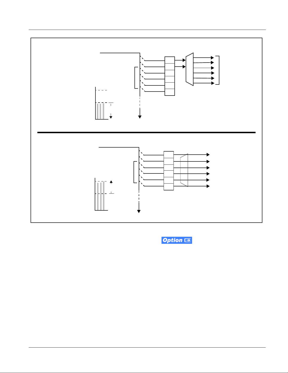
2.0-to-5.1 Upmixer. The 2.0-to-5.1 upmixer function
receives a normal PCM stereo pair from any internal bus channel pair. The
stereo pair is upmi xed to prov ide 5.1 chan nels (Lef t (
Low Frequency Effects (
LFE), Left Surround (Ls), and Right Surround (Rs)).
L), Right (R), Center (C),
Whenever the upmixer is active, it overwrites the six selected 5.1 output
channels with the new 5.1 upmix signals (including replacing the original
source stereo
L and R inputs with new L and R signals).
9931-EMDE-OM (V1.15) 9931-EMDE PRODUCT MANUAL 1-17
Page 22

1 9931-EMDE Functional Description
The 2.0-to-5.1 upmixer can be set to upmix in any of three modes: Always
upmix, Bypass upmix, or Auto enable/bypass upmixing. The Auto upmixing
mode looks at the s ignal le vels on t he selec ted ch annels an d compar es them to
a selectab le level threshold. It the n determines whether or not to generate 5.1
upmixing from the ster eo pair as follows:
• If the upmixer detects signal level below a selected threshold on all
three of the selected channels designated as
indicates to the upmixer that these channels are not carrying 5.1. In
this case, the upmixer produces new 5.1 content generated by the
upmixer.
• If the upmixer detects signal level above a selected threshold on any
of the three selected channels designated as
indicates t o the upmixe r that the ch annel(s) ar e already carrying
viable 5.1 content. In this case, the upmixer is bypassed and the
channels fed to the upmixer pass unaffected to the upmixer outputs.
The examples in Figure 1-8 show t he automatic enable/di sable upmixing
function applied to example selected channels
shown and described, the processing is contingent upon the signal levels of
the channe ls selected to carry the new 5.1 upmix relative to the selected
threshold (in this example, -60 dBFS).
C, Ls, and Rs, this
C, Ls, and Rs, this
Bus Ch 1 thru Bus Ch 6. As
1-18 9931-EMDE PRODUCT MANUAL 9931-EMDE-OM (V1.15)
Page 23
Introduction 9931-EMDE Functional Description
From
Internal
With all detected signal levels on
Bus Ch 3, 5 and 6 below
threshold, upmixer is active and
generates new 5.1 content.
- 20 dBFS
- 60 dBFS
From
Internal
With any detected signal levels
on Bus Ch 3, 5 or 6 above
threshold, upmixer is bypassed.
- 20 dBFS
- 60 dBFS
Bus
Bus
>
C
>
Bus Ch 1 – Ch 16
Below Threshold
(Overwrite)
s
s
L
R
Bus Ch 1 – Ch 16
Above Threshold
(Bypass)
Bus Ch 1
Bus Ch 2
Bus Ch 3
Bus Ch 4
Bus Ch 5
Bus Ch 6
Bus Ch 1
Bus Ch 2
Bus Ch 3
Bus Ch 4
Bus Ch 5
Bus Ch 6
Threshold
Detect
L
R
(C)
(LFE)
(Ls)
(Rs)
Threshold
Detect
L
R
(C)
(LFE)
(Ls)
(Rs)
5.1 Upmix
Upmix L
Upmix R
Upmix C
LFE
Upmix Ls
Upmix Rs
Upmix outputs
consist of new
upmix content
Because the selected
channels are already carrying
viable content, upmixing is
bypassed, allowing the six
original Bus Ch 1 – Ch 6 to
pass through upmix outputs
Upmix L thru Upmix Rs
unmodified.
s
s
C
L
R
Figure 1-8 Upmixing Auto Enable/Bypass wit h Example So urces
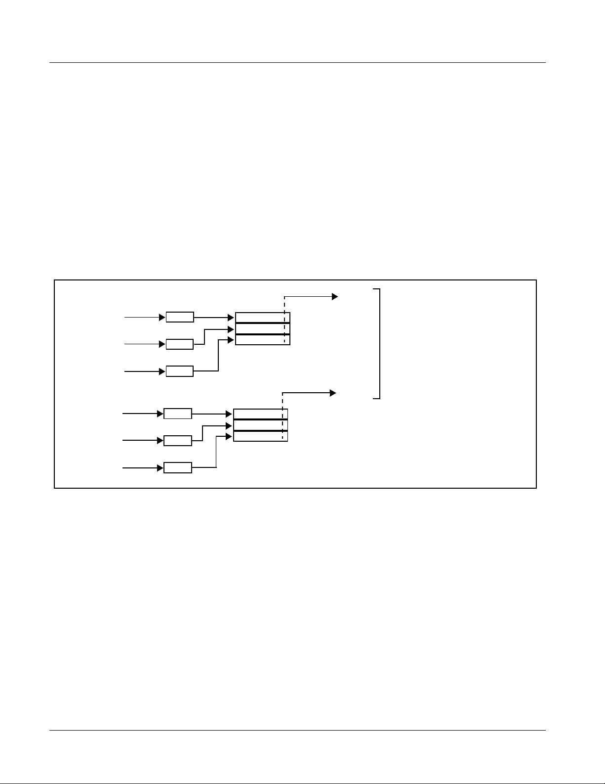
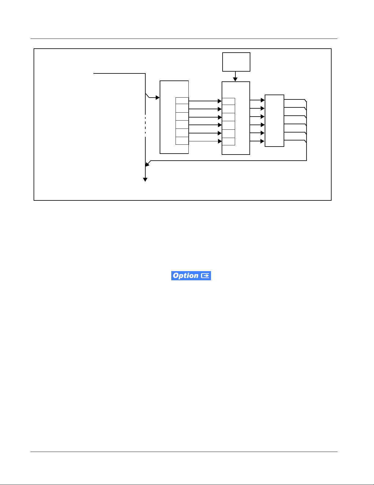
Loudness Processor. (See Figure 1-9.) The loudness
processor function receives up to six selected channels from the internal bus
and performs loudness processing on the selected channels. A loudness
processing profile best suited for the program material can be selected from
several loudness processing presets. Refer to catalog or Fusion3G
®
supplement OPT-SW-F3GLP-MS for more information.
Note: Discussion and example here describes 5.1-channel loudness processor.
Stereo and dual-stereo processors operate similar to described here.
The example in Figure 1-9 shows routing of embedded output channels Emb
Out Ch 1 thru Ch 6 fed through the loudness processor. A master output gain
control is provided which allows fine adjustment of the overall output level.
manual
9931-EMDE-OM (V1.15) 9931-EMDE PRODUCT MANUAL 1-19
Page 24
1 9931-EMDE Functional Description
Processing
Preset
Select
From Internal Bus
Bus Ch 1– Ch 6
>
Loudness processor provides loudness-processed outputs LP51 - L thru LP51 - Rs,
which are available as source selections for card audio output routing.
To Output Audio
Routing/Controls
Input/Output
Select
L
R
(C)
(LFE)
(Ls)
(Rs)
Bus Ch 1
Bus Ch 2
Bus Ch 3
Bus Ch 4
Bus Ch 5
Bus Ch 6
Loudness
Processing
L
R
(C)
(LFE)
(Ls)
(Rs)
Control
Figure 1-9 5.1-Channel Loudness Processor with Example Sources
Tone Generators. The 9931-EMDE contains eight built-in tone generators
of frequencies from 50 Hz to 16 kHz. Eac h of the eight tone generator s can be
routed to the upmixer or directly to card audio outputs.
(Default output is -20 dBFS.)
Master
Output
Gain
LP51-L
LP51-R
LP51-C
LP51-LFE
LP51-Ls
LP51-Rs
DashBoard Dual Audio Loudness Meter
Description.
Note: This function provides DashBoard loudness metering and is typically fur-
nished with cards licensed for loudness processing. OGCP-9000 Loudness
Meter Option (+LM) is an OGCP-9000 Control Panel option that provides
advanced loudness metering functions such as graphing and statistics. +LM
option is separate and independent of this function; refer to catalog or website
for more information.
This function allows two independent 5.1-channel PCM groups to be routed
to two independent DashBoard loudness meters that provide short-term
loudness measurement in accorda nce with ITU-R BS.1770- 1 – ATSC A/85.
The function can monitor any combination of channels on the card internal
bus, or audio DSP output channels such as upmixed and loudness-processed
channels (channel routing to the meters is independent of any other card
routing and does not af fect the channe ls in any way). The two lo udness meters
readily allow pre and post-processed loudness processing comparison when
loudness processing is being performed by the card.
The function provides a configurable short term window for tailoring the
measurement to suit various program material conditions.
1-20 9931-EMDE PRODUCT MANUAL 9931-EMDE-OM (V1.15)
Page 25

Introduction 9931-EMDE Functional Description
Control and Data Input/Output Interfaces
GPI Interface
Two independent ground-closure sensing GPI inputs (GPI 1 and GPI 2; each
sharing common ground connection as chassis potential) are available.
Associated with each GPI use r control is a s elect io n of one o f 64 use r -def ined
card presets in which GPI activation invokes a card control prese t. Because
the GPI closure invokes a user-defined preset, the result ing setup is highly
flexible and totall y user-defined. Invoking a user preset to effect a change
involves card setup communication limited only to the items being changed;
the card remains on-line during the setup, and the called preset is rapidly
applied.
GPI triggering can be user selected to consider the activity on discrete GPI
ports, or combinations of logic states considering both GPI inputs. This
flexibility allows multistage, progressive actions to be invoked if desired.
Indication is provided showing whenever a GPI input has been invoked.
GPO Interface
Two independent SPST NO electromechanical non-referenced (floating)
contact pairs (
GPO 1/1 and GPO 2/2) are available. A GPO can be invoked by
setting a GPO to be enabled when a card pres et is in tur n appli ed (i.e., when a
preset is invoked (either manually or via event-based loading), the GPO is
correspondingly also activated.
Serial (COMM) Ports
The 9931-EMDE is equipped with two, 3-wire serial ports (COM 1 - Serial
Port 1, COM 2 - Serial Port 2). The ports allow serial metadata import and
export between optional Dolby
provide for SMPTE 2020 de-embedding to an output port, and provide
RS-485 LTC I/O (when licensed with option +LTC).
®
encoders and decoders. The ports also
9931-EMDE-OM (V1.15) 9931-EMDE PRODUCT MANUAL 1-21
Page 26
1 9931-EMDE Functional Description
User Control Interface
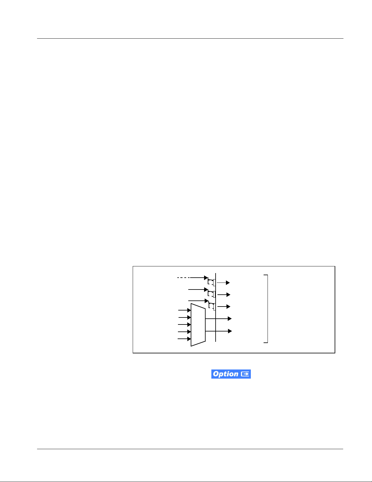
Figure 1-10 shows the user control interface options for the 9931-EMDE.
These interfaces are individually described below.
Note: All user control interfaces described here are cross-compatible and can oper-
ate together as desired. Where applicable, any control setting change made
using a particular user interface is reflected on any other connected interface.
OGCP-9000 Control Panel
OGCP-9000/CC Control Panel
Computer
with NIC
or
DashBoard™ Remote Control
Using a computer with
DashBoard™ installed,
9931-EMDE card can be
remotely controlled over a LAN
Remote Control Panel
Using the Control Panel,
9931-EMDE card can be
remotely controlled over a LAN
LAN
20-Slot Frame with Network Controller Card
In conjunction with a frame equipped
with a Network Controller Card,
9931-EMDE card can be remotely
controlled over a LAN
Note: • To communicate with DashBoard™ or a Remote Control Panel, the frame must have the optional
MFC-8320-N network controller card installed.
• DashBoard™ and the Remote Control Panels provide network control of the 9931-EMDE as
shown. The value displayed at any time on the card, or via DashBoard™ or a Control Panel is the
actual value as set on the card, with the current value displayed being the actual value as effected
by the card. Parameter changes made by any of these means are universally accepted by the
card (for example, a change made using DashBoard™ controls will change the setting displayed
on both DashBoard™ and a Control Panel; a change made using a Control Panel will similarly
change the setting displayed on the Control Panel and DashBoard™).
Figure 1-10 9931-EMDE User Control Interface
1-22 9931-EMDE PRODUCT MANUAL 9931-EMDE-OM (V1.15)
Page 27

Introduction 9931-EMDE Functional Description
• DashBoard™ User Interface – Using DashBoard™, the
9931-EMDE and other cards i nst al le d i n openGear®
the Cobalt
®
HPF-9000 or 8321 Frame can be controlled from a
1
frames such as
computer and monitor.
DashBoard™ allows users to view all frames on a network with
control and monitoring for all populated slots inside a frame. This
simplifies the setup and use of numerous modules in a large
installation and offers the ability to centralize monitoring. Cards
define thei r controllable parameters to DashBoard™, so the control
interface is always up to date.
The DashBoard™ software can be downloaded from the Cobalt
Digital Inc. website: www.cobaltdigital.com
(enter “DashBoard” in
the search window). The DashBoard™ user interface is describe d in
Chapter 3,“Operating Instructions”.
Note: If network remote control is to be used for the frame and the frame has not yet
been set up for remote control, Cobalt
User Guide (PN 9000RCS-RM) provides thorough information and
step-by-step instructions for setting up network remote control of COMPASS
and FUSION3G
OGCP-9000/CC Remote Control Panel product manuals have complete
instruct ions for setting up remote control using a Remote Control Panel.)
Download a copy of this guide by clicking on the Support>Documents>
Reference Guides link at www.cobaltdigital.com and then select DashBoard
Remote Control Setup Guide as a download, or contact Cobalt
Contact Cobalt Digital Inc. (p. 1-32).
®
cards using DashBoard™. (Cobalt® OGCP-9000 and
®
reference guide Remote Control
®
as listed in
®
• Cobalt
®
OGCP-9000 and OGCP-9000/CC Remote Control
Panels – The OGCP-9000, OGCP-9000/CC, and WinOGCP Remote
Control Panels conveniently and intuitively provide parameter
monitor and control of the cards within the 20-slot frame.
The remote control panels allow quick and intuitive access to
hundreds of cards in a facility, and can mo nit or and a ll ow adj us tment
of multiple parameters at one time.
The remote contro l panels are totally compatible wit h the openGear
®
control software DashBoard™; any changes made with either system
are reflected on the oth er.
1. openGear® is a registered trademark of Ross Video Limited. DashBoard™ is a trademark of Ross
Video Limit e d .
9931-EMDE-OM (V1.15) 9931-EMDE PRODUCT MANUAL 1-23
Page 28
1 9931-EMDE Functional Description
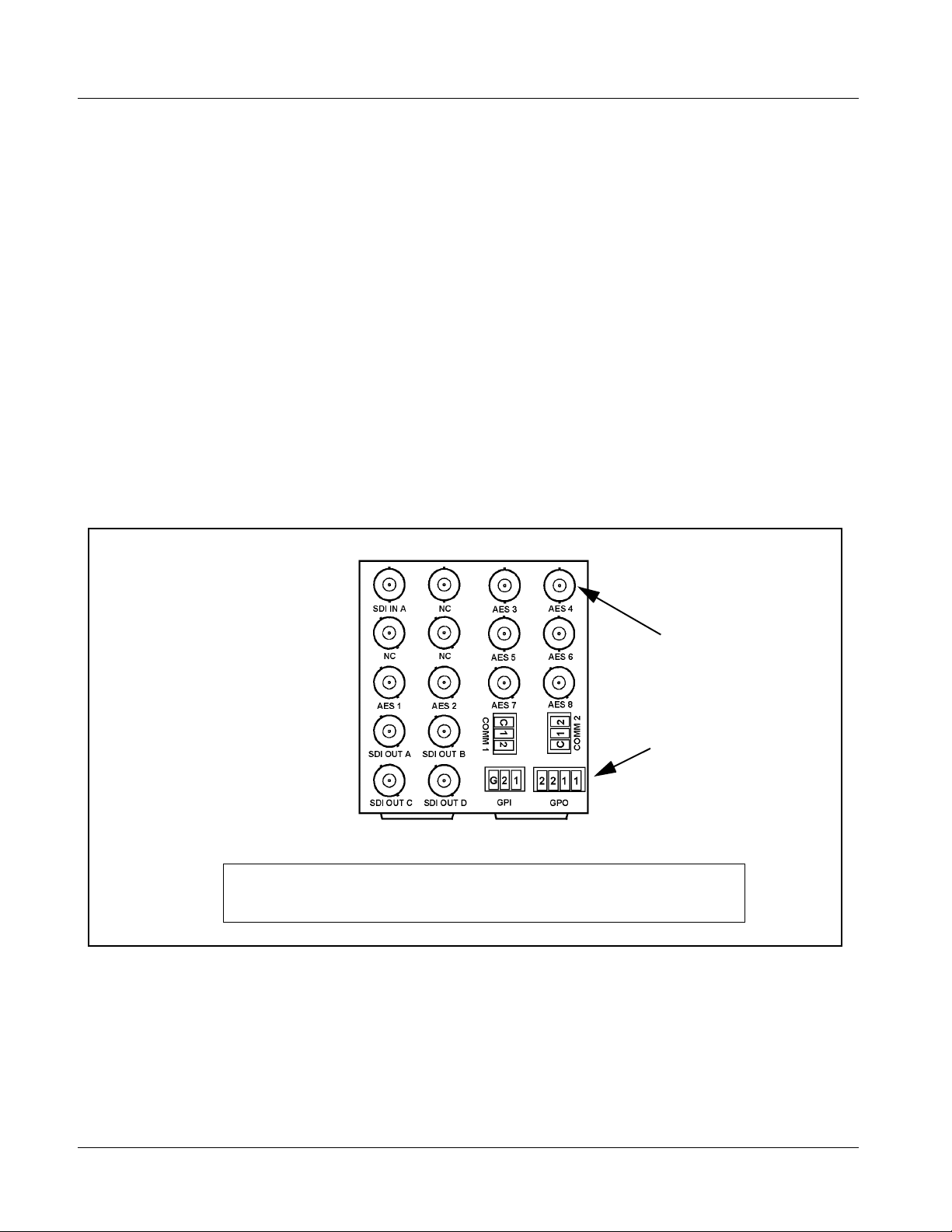
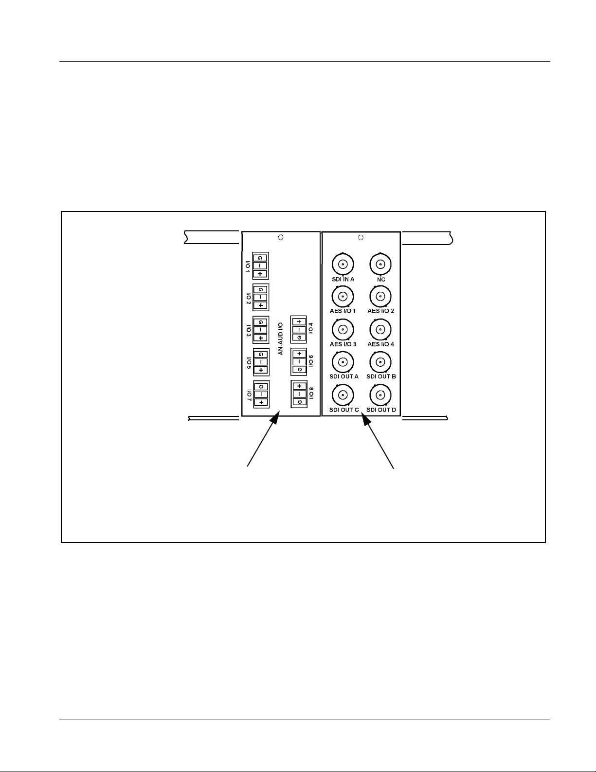
9931-EMDE Rear Modules
The 9931-EMDE physically inte rfaces to syste m video and audio connect ions
using a Rear Module. Figure 1-11 shows a typical 9931-EMDE Rear Module.
All inputs and outputs shown in the video and audio block diagr ams (Fi gur es
1-2 and 1-5, respectively) enter and exit the card via the card edge backplane
connector. The Rear Module breaks out the 9931-EMDE card edge
connections to industry standard connections that interface with other
components and systems in the signal chain.
In this manner, the particular inputs and outputs required for a particular
application can be accommodated using a Rear Module that best suits the
requirements. The required input and outputs are broken out to the industry
standard connectors on the Rear Module; the unused inputs and outputs
remain unterminated and not available for use.
The full assortment of 9931-EMDE Rear Modules is shown and described in
9931-EMDE Rear Modules (p. 2-7) in Chapter 2, “Installation and S etu p”.
BNC connectors for coaxial
video and AES audio signals
Multi-terminal Phoenix terminal
block connectors (for balanced
analog audio signals and other
unterminated wiring)
In this example, an RM20-9931-E Rear Module provides a connection interface for the signal
types shown here.
Figure 1-11 Typical 9931-EMDE Rear Module
1-24 9931-EMDE PRODUCT MANUAL 9931-EMDE-OM (V1.15)
Page 29
Introduction 9931-EMDE Functional Description
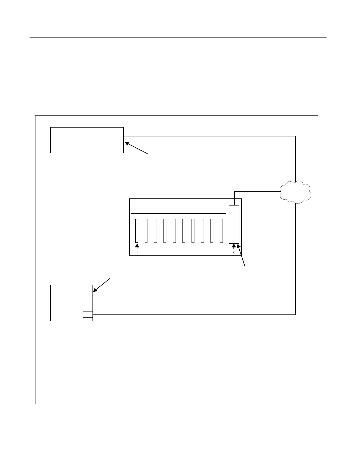
For some card options, a piggyb ack car d is mount ed to t he main 99 31-E MDE
card. Occupying two card slots, the connections for the functions offered by
the piggyback card are broken out using an expansion module (which is
installed adjacent to the base card rear module slot). When an expansion rear
module is used, the base rear module mates with the base Fusion3G
and the expansion rear module mates with the expansion piggyback card that
is piggyback-installed on the base card.
Figure 1-12 shows a 9931-EMDE card using an RM20-9931-B base rear
module along with an analog audio expansion rear module.
®
card,
REAR VIEW OF FRAME
Expansion Rear Module installs on slot directly to the left
of base Rear Module, and interfaces with the piggyback
card. In this example, an expansion rear module breaks
out analog audio connections provided by analog audio
options.
Figure 1-12 9931-EMDE with Expansion Rear Module
RM20-9931-B Rear Module provides connection
break-out for base card functions.
9931-EMDE-OM (V1.15) 9931-EMDE PRODUCT MANUAL 1-25
Page 30

1 Technical Specifications
Audio and Video Formats Supported by the 9931-EMDE
Table 1-3 lists and provides details regarding the audio and video formats
supported by the 9931-EMDE.
Table 1-3 Supported Audio and Video Formats
Item Description/Specification
Input / Output Video Raster Structure: Frame Rate:
1080p 23.98; 24; 29.97; 25; 30
(1)
(1)
(1)
(2)
50; 59.94; 60
25; 29.97; 30
59.94; 60
29.97
25
1080p 3G
1080i
720p 23.98; 24; 25; 29.97; 30; 50;
486i
575i
Embedded Audio The 9931-EMDE supports all four groups (16 channels) of embedded
audio at full 24-bit resolution in both SD (with extended data packets)
and HD.
Analog Audio The 9931-EMDE supports 8 channels of balanced (differential) analog
audio (maximum total of inputs and outputs). The analog audio is
encoded such that a +24 dBu input is equivalent to digital 0 dBFS.
Discrete AES Audio The 9931-EMDE can accept 16 channels (8 pairs) of discrete AES
audio on 75Ω BNC connections (maximum total of inputs and outputs).
Sample rate conversion can be employed to accommodate sample rate
differences in the AES stream and the input video stream.
(1) All rates displayed as frame rates; interlaced (“i”) field rates are two times the rate value shown.
(2) Not supported as analog video I/O formats.
Technical Specifications
Table 1-4 lists the technical specifications for the 9931-EMDE 3G/HD/
SD-SDI Embedder/De-Embedder card.
Note: Input/output types and number of input/outputs in some cases are a function
of option(s) and/or rear module installed. Input/outputs requiring options are
specified below. Refer to Table 1-1, “9931-EMDE Video/Audio Signal Types”
for detailed information on available input/output complements and corresponding options/rear module requirements.
1-26 9931-EMDE PRODUCT MANUAL 9931-EMDE-OM (V1.15)
Page 31

Introduction Technical Specifications
Table 1-4 Technical Specifica tions
Item Characteristic
Part number, nomenclature • 9931-EMDE 3G/HD/SD-SDI Embedder/De-Embedde r
• 9931-EM 3G/HD/SD-SDI Embedder
• 9931-DE 3G/HD/SD-SDI De-Embedder
Installation/usage environment Intended for installation and usage in frame meeting openGear
Power cons umption 28 Watts (nominal)
Environmental:
Operating temperature:
Relative humidity (operating or storage):
Frame communication 10/100 Mbps Ethernet with Auto-MD IX.
Internal Tone Generators Eight built-in tone generators, each configurable for 18 discrete sine
Standards Supported (SDI) 3G: SMPTE 425 level A
BNC SDI Video Inputs/Outputs Input/Output Complement:
modular system definiti on.
The following options add power consumption as follows:
• +DEC (Dolby
• +ANA, +ANV (analog audio/video I/O) options: 15 Watts (typical)
32° – 104° F (0° – 40° C)
< 95%, non-condensing
wave frequencies ranging from 50 Hz to 16 kHz.
Generator source signal level is equivalent to -20 dBu.
1080p60, 1080p59.94, 1080p50
HD: 1080i60, 1080i59.94, 1080i50, 1080p29.97, 1080p25, 1080p24;
1080p23.98
720p60, 720p59.94, 720p50, 720p29.97, 720p25, 720p24,
720p23.98
SD: 486i59094, 576i50
• One BNC input connector
• Four BNC output connectors
Data Rates Supported:
SMPTE 425 level A and B: 3 Gbps
SMPTE 292 HD-SDI: 1.485 Gbps or 1.485/1.001 Gbps
SMPTE 259M-C SD-SDI: 270 Mbps
BNC Connector Input/Output Impedance:
75 Ω terminating
Cable Equal ization (3G) :
394 ft (120 m) Belden 1694A
Cable Equalization (HD):
591 ft (180 m) Belden 1694A
Cable Equalization (SD):
1050 ft (320 m) Belden 1694A
Return Loss:
> 15 dB up to 1.485 GHz
®
decoder) option: 2 Watts
®
9931-EMDE-OM (V1.15) 9931-EMDE PRODUCT MANUAL 1-27
Page 32

1 Technical Specifications
Table 1-4 Technical Specifications — continued
Item Characteristic
Fiber Inputs/Outputs
(option required)
Analog Video Input
(option required)
Input/Output Complemen t:
Up to two inputs/outputs (maximum total between inputs and outputs)
Connectors:
Dual LC, standard polish
Fiber Type:
9/125 micron, single mode
Mating System:
Blindmate
Tx Power:
-5 dBm @ 1310 nm
Rx Power:
-16 to -3 dBm @ 1260 to 1620 nm
Input Complement:
Separate compone nt and com posite in put s on 75 Ω BNC connectors.
Supports component HD/SD and com ponent, compos ite, and Y/C SD
inputs.
Video Input Types:
HD: Component YPbPr and RGB SMPTE
SD: Composite, Component YPbPr (BetaCam™, MII™,
SMPTE/N10), RGB, and Y/C
ADC Bit Depth:
12 bit
Sampling:
54 MHz (4x oversampling)
Frequency Response:
Y/CVBS: ± 0.25 dB to 30 MHz
Pb/Pr: ± 0.25 dB to 15 MHz
Noise:
< -60 dB to 30 MHz (unweighted)
Differential Phase:
<1.5°
Differential Gain:
<1.0%
Analog Video Output
(option required)
Output Complement:
Separate component and composite outputs on 75 Ω BNC
connectors. Support s compon ent HD/SD an d component, composite,
and Y/C SD outputs.
Video Output Types:
HD: Component YPbPr and RGB SMPTE
SD: Composite, Component YPbPr (BetaCam™, MII™,
SMPTE/N10), RGB, and Y/C
1-28 9931-EMDE PRODUCT MANUAL 9931-EMDE-OM (V1.15)
Page 33

Introduction Technical Specifications
Table 1-4 Technical Specifica tions — continued
Item Characteristic
Analog Video Output
(option required)
(cont.)
AES Audio Inputs/Outputs Standard:
DAC Bit Depth:
12 bit
Frequency Respon se:
Y/CVBS: ± 0.25 dB to 30 MHz
Pb/Pr: ± 0.25 dB to 15 MHz
Noise:
< -60 dB to 30 MHz (unweighted)
Differential Phase:
<1.5°
Differential Gain:
<1.0%
SMPTE 276M
Number of inputs/outputs (maximum total between inputs and outputs):
8 pairs (16-channel) on BNC connectors per AES3-id; 75 Ω
impedance
Input Level:
0.2 to 2.0 Vp-p
Output Level:
1.0 Vp-p
Return Loss:
> 15 dB @ up to 6.144 MHz
Input SRC Range:
32 kHz to 96 kHz
Input SRC Performance:
>130 dB THD+N
Analog Audio Inputs/Outputs
(option required)
Audio Delay Configurable Audio Delay:
Number of inputs/outputs (maximum total between inputs and outputs):
Eight, 3-wire balanced analog audio using Phoenix connectors with
removable screw te rminal blocks (Phoenix PN 1803581; Cobalt PN
5000-0013-000R)
Input Impedance:
>10 kΩ
Input Clip Level:
+24 dBu (eq. 0 dBFS)
Max. Output Level:
+24 dBu (eq. 0 dBFS)
Frequency Respon se:
± 0.12 dB (20 Hz to 20 kHz)
SNR:
115 dB (A-weighted)
THD+N:
-96 dB (20 Hz to 10 kHz)
Crosstalk:
-106 dB (20 Hz to 20 kHz)
16-channel; independent delay per channel; 1 sample step size
Up to 5 sec delay for each channel
9931-EMDE-OM (V1.15) 9931-EMDE PRODUCT MANUAL 1-29
Page 34

1 Technical Specifications
Table 1-4 Technical Specifications — continued
Item Characteristic
Serial Ports Two ports, each 3-wire RS-485 using Phoenix connectors with
GPI Ports Two opto - isola t ed po rt s with s elf-s ou rci ng cu rrent on 3-w i re (I N 1, IN 2,
GPO Ports Two, indepe nde nt non -refe renc ed (floati ng) SPST relay closure
removable screw terminal blocks (Phoenix PN 1803581; Cobalt PN
5000-0013-000R)
Rx Functions:
Closed captioning input, Dolby
Tx Functions:
Closed captioning output, Dolby
GND) Phoenix connector with removable screw terminal blocks
(Phoenix PN 1803581; Cobalt PN 5000-0013-000R)
Triggering:
User-configurable. GPI activation invokes a selected user preset.
Response:
GPI acknowledge upon falling-edge input triggered
by R ≤ 10 kΩ (or Vin ≤ 2.0 V)
GPI release upon rising-edge input triggered
by R ≥ 10 kΩ (or Vin ≥ 2.0 V)
“G” (GND) terminal at chassis-ground potential
Suitable for use with 3.3V LVCMOS logic
Maximum Recommended Logic Control Voltage Range:
0 to 5 VDC
indicating input path selected (either via manual or failover selection).
GPO can be selected to trigger upon engagement of a specified user
preset.
Response:
Closure effected for duration of true status condition; closure release
upon false status condition
Maximum Recommended Voltage / Current:
12 VDC @ 100mA max.
Connector: 4-terminal Phoenix; GPO1/GPO1C / GPO2/GPO2C
®
metadata input, RS-485 LTC IN
®
metadata output, RS-485 LTC OUT
1-30 9931-EMDE PRODUCT MANUAL 9931-EMDE-OM (V1.15)
Page 35

Introduction Warranty and Service Information
Warranty and Service Information
Cobalt Digital Inc. Limited Warranty
This product is warranted to be free from defects in material and workmanship for a period of five (5)
years from the date of shipment to the original purchaser, except that 4000, 5000, 6000, 8000 series
power supplies, and Dolby
material and workmanship for a period of one (1) year.
Cobalt Digital Inc.'s (“Cobalt”) sole obligation under this warranty sh all be limited to, at its option, (i)
the repair or (ii) replacement of the produc t, and the det ermination of whether a defect is covered under
this limited warranty shall be made at the sole discretion of Cobalt.
This limited warrant y appl ies on ly t o the origi nal end-pu rchaser of the produ ct, and i s not assign able o r
transferrable therefrom. This warr ant y i s li mited to defects in material and workmanship, and shall not
apply to acts of God, accidents, or negligence on behalf of the purchaser, and shall be voided upon the
misuse, abuse, alteration, or modification of the product. Only Cobalt authorized factory
representatives are authorized to make repairs to the product, and any unauthorized attempt to repair
this product shall immediately void the warranty. Please contact Cobalt Technical Support for more
information.
®
modules (where applicable) are warranted to be free from defects in
To facilitate the resolut ion of warranty related issues, Cobalt recommends registering the product by
completing and returning a product registration form. In the event of a warrantable defect, the
purchaser shall notify Cobalt with a descripti on of the problem, and Cobalt shall provide the purchaser
with a Re turn Mate rial Auth oriz ation (“RMA”). For retu rn, defective product s should be double boxed,
and sufficiently protecte d, in the original packa ging, or equivalent, a nd shipped to the Coba lt Factory
Service Center, postage prepaid and insured for the purchase price. The purchaser should include the
RMA number, description of the problem encountered, date purchased, name of dealer purchased
from, and serial number with the shipment.
Cobalt Digital Inc. Factory Service Center
2406 E. University Avenue Office: (217) 344-1243
Urbana, IL 61802 USA Fax: (217) 344-1245
www.cobaltdigital.com Email: info@cobaltdigital.com
THIS LIMITED WARRANTY IS EXPRESSLY IN LIEU OF ALL OTHER WARRANTIES
EXPRESSED OR IMPLIED, INCLUDING THE WARRANTIES OF MERCHANTABIL ITY AND
FITNESS FOR A PARTICULAR PURPOSE AND OF ALL OTHER OBLIGATIONS OR
LIABILITIES ON COBALT'S PART. ANY SOFTWARE PROVIDED WITH, OR FOR USE WITH,
THE PRODUCT IS PROVIDED “AS IS.” THE BUYER OF THE PRODUCT ACKNOWLEDGES
THAT NO OTHER REPRESENTATIONS WERE MADE OR RELIED UPON WITH RESPECT TO
THE QUALITY AND FUNCTION OF THE GOODS HEREIN SOLD. COBALT PRODUCTS ARE
NOT AUTHORIZED FOR USE IN LIFE SUPPORT APPLICATIONS.
COBALT'S LIABILITY, WHETHER IN CONTRACT, TORT, WARRANTY, OR OTHERWISE, IS
LIMITED TO THE REPAIR OR REPLACEMENT, AT ITS OPTION, OF ANY DEFECTIVE
PRODUCT, AND SHALL IN NO EVENT INCLUDE SPECIAL, INDIRECT, INCIDENTAL, OR
CONSEQUENTIAL DAMAGES (INCLUDING LOST PROFITS), EVEN IF IT HAS BEEN
ADVISED OF THE POSSIBILITY OF SUCH DAMAGES.
9931-EMDE-OM (V1.15) 9931-EMDE PRODUCT MANUAL 1-31
Page 36

1 Contact Cobalt Digital Inc.
Contact Cobalt Digital Inc.
Feel free to contact our thorough and professional support representative s for
any of the following:
• Name and address of your local dealer
• Product information and pricing
• Technical support
• Upcoming trade show in formation
Phone: (217) 344-1243
Fax: (217) 344-1245
Web: www.cobaltdigital.com
General Information: info@cobaltdigital.com
Technical Support: support@cobaltdigital.com
1-32 9931-EMDE PRODUCT MANUAL 9931-EMDE-OM (V1.15)
Page 37

Overview
Chapter 2
Chapter 2 Installation and Setup
This chapter contains the following information:
• Setting I/O Switches for Anal og Audio (1-8) Ports (p. 2-1)
• Installing the 9931-EMDE Into a Frame Slot (p. 2-2)
• Installing a Rear Module (p. 2-4)
• Connecting To Phoenix Terminal Connectors (p. 2-15)
• Setting Up 9931-EMDE Network Remote Control (p. 2-15)
Note: The 9931-EMDE is suitable for installation only in a 20-slot frame (Cobalt® PN
HPF-9000, OG3-FR, or 8321-CN or equivalent).
Setting I/O Switches for Analog Audio (1-8) Ports
Notes: • This procedure is applicable only for 9931-EMDE equipped with analog
audio options (for example, option +ANAIO). Refer to catalog or Fusion3G
manual supplement Analog Audio/Video Options OPT-F3GAN-MS for more
information.
• All switches are set as inputs as factory default.
Analog audio options allow the 9931-EMDE to be used with analog audio
inputs and/or outputs. The option provides for eight analog audio channel IN
or OUT, with each channel configurable as an input or output using DIP
switches S1 thru S8). The switches are located on the option piggyback card.
Note switch S1 thru S8 locat ions f or
Figure 2-1. For port to be used as an output, set switch to down position as
shown in Figure 2-1.
AN-AUD I/O 1 thru AN-AUD I/O 8 shown in
®
9931-E MDE-O M (V1.15) 9931-EMDE PRODUCT MANUAL 2-1
Page 38

2 Installing the 9931-EMDE Into a Frame Slot
AN-AUD I/O 4
AN-AUD I/O 3
AN-AUD I/O 2
AN-AUD I/O 1
S1
S2 S3 S4
IN
OUT
IN
OUT
IN
OUT
IN
OUT
Rear of Card
S5
AN-AUD I/O 5
AN-AUD I/O 6
AN-AUD I/O 7
AN-AUD I/O 8
S6 S7 S8
IN
OUT
IN
OUT
IN
OUT
IN
OUT
Figure 2-1 9931-EMDE AN-AUD I/O (1-8) Mode Switches
Installing the 9931-EMDE Into a Frame Slot
CAUTION
Heat and power distribution requirements within a frame may dictate specific
slot placement of cards. Cards with many heat-producing components should
be arranged to avoid areas of excess heat build-up, particularly in frames
using only convection cooling. The 9931-EMDE has a moderate power
dissipation (20 W max.). As such, avoiding placing the card adjacent to other
cards with similar dissipation values if possible.
CAUTION
This device contains semiconductor devices which are
susceptible to serious damage from Electrostatic
Discharge (ESD). ESD damage may not be immediately
apparent and can affect the long-term reliability of the
device.
Avoid handling circuit boards in high static environments
such as carpeted areas, and when wearing synthetic fiber
clothing. Always use proper ESD handling precautions
and equipment when working on circuit boards and
related equipment.
CAUTION
If required, make certain Rear Module(s) is installed before installing the
9931-EMDE into the frame slot. Damage to card and/or Rear Module can occur
if module installation is attempted with card already installed in slot.
2-2 9931-EMDE PRODUCT MANUAL 9931-EMDE-OM (V1.15)
Page 39

Installation and Setup Installing the 9931-EMDE Into a Frame Slot
Notes: • Check the packaging in which the 9931-EMDE was shipped for any extra
items such as a Rear Module connection label. In some cases, this label is
shipped with the card and to be installed on the Rear I/O connector bank
corresponding to the slot location of the card.
• Depending on option(s) ordered, the 9931-EMDE unit may consist of a main
card and a piggyback option card. If equipped with a piggyback card, both
cards as a unit will require simultaneous alignment with slot guides and
rear modules in the following steps.
Install the 9931-EMDE into a frame slot as follows:
1. Determine the slot in which the 9931-EMDE is to be installed.
2. Open the frame front access panel.
3. While holding the card by the card edges, align the card such that the
plastic ejector tab is on the bottom.
4. Align the card with the top and bottom guides of the slot in which the
card is being installed.
5. Gradually slide the card into the slot. When resistance is noticed, gently
continue pushing the card until its rear printed circuit edge terminals
engage fully into the Rear Module mating connector.
CAUTION
If card resists fully engaging in Rear Module mating connector, check for
alignment and proper insertion in slot tracks. Damage to card and/or Rear
Module may occur if improper card insertion is attempted.
Verify that the card is fully engaged in Rear Module mating connector.
6.
7. Close the frame front access panel.
8. Connect cabling in accordance with the appropriate diagram shown in
Table 2-1, “9931-EMDE Rear Modules” (p. 2-7).
9. Repeat steps 1 through 8 for other 9931-EMDE cards.
Notes: • The 9931-EMDE BNC inputs are internally 75-ohm terminated. It is not nec-
essary to terminate unused BNC inputs or outputs.
• To remove a card, press down on the ejector tab to unseat the card from the
Rear Module mating connector. Evenly draw the card from its slot.
10. If network remote control is to be us ed for the frame and the frame has
not yet been set up for remote control, perform setup in accordance with
Setting Up 9931-EMDE Network Remote Control (p. 2-15).
Note: If installing a card in a frame already equipped for, and connected to
DashBoard™, no network setup is required for the card. The card will be discovered by DashBoard™ and be ready for use.
9931-EMDE-OM (V1.15) 9931-EMDE PRODUCT MANUAL 2-3
Page 40

2 Installing a Rear Module
Installing a Rear Module
Notes: • This procedure is applicable only if a Rear Module is not currently
installed in the slot where the 9931-EMDE is to be installed.
• Where options are furnished using a piggyback card mounted to
9931-EMDE main card, base Rear Module must be installed in frame
location such that Rear Module interfaces with base card. Expansion Rear
Module must be installed in frame location such that Rear Module interfaces
with expansion (piggyback) card (see Figure 2-3).
• Note that some Rear Modules and labels have several ventilation holes. To
allow maximum ventilation, it is recommended to place the label fully over
connectors such that label is flush with rear module and holes are not
obscured. Also, when a card is not installed in a slot, it is recommended that
the supplied blank cover be used to preserve proper forced ventilation
flow-through.
The full assortment of 9931-EMDE Rear Modules is shown and described in
9931-EMDE Rear Modules (p. 2-7). Install a Rear Module as follows:
1. On the frame, determine the slot in which the 9931-EMDE is to be
installed.
2. In the mounting area corresponding to the slot location, install
Rear Module as shown in Figure 2-2.
3. If an expansion Rear Module is to be i nstalled, install it adjacent to the
base Rear Module a s shown in F igure 2-3.
2-4 9931-EMDE PRODUCT MANUAL 9931-EMDE-OM (V1.15)
Page 41

Installation and Setup Installing a Rear Module
Align and engage mounting tab on Rear
I/O Module with the module seating slot
1
on rear of frame chassis.
DSCN3483A.JPG
Hold top of Rear Module flush against
frame chassis and start the captive screw.
2
Lightly tighten captive screw.
Note: Rear Modules RM20-9931-E occupies two rear module slot
mounting locations and use two captive screws.
DSCN3487A.JPG
Figure 2-2 Rear Module Installation
9931-EMDE-OM (V1.15) 9931-EMDE PRODUCT MANUAL 2-5
Page 42

2 Installing a Rear Module
REAR VIEW OF FRAME
Expansion Rear Module Base Rear Module
Fusion3G expansion
card and Exp an s i on
Rear Module
Fusion3G bas e
card and Bas e
Rear Module
Expansion Rear Module always mates to expansion piggyback card. Expansion Rear Module installs on slot directly to the left of
base Rear Module.
Note: Where a base -HV rear module is to be used in conjunction with an expansion rear module, a companion -HV expansion
rear module must also be used. Both base and expansion HV rear modules use card positioning that optimizes air flow across
the component surface of the card PCB.
Figure 2-3 9931-EMDE with Expansion Rear Module
2-6 9931-EMDE PRODUCT MANUAL 9931-EMDE-OM (V1.15)
Page 43

Installation and Setup Installing a Rear Module
9931-EMDE Rear Modules
Table 2-1 shows and describes the full assortment of Rear Modules
specifical ly for use with the 9931-EMDE.
Notes: • Rear Modules equipped with multi-wire Phoenix connectors are supplied
with removable screw terminal block adapters. For clarity, the adapters are
omitted in the drawings below. Refer to Connecting To Phoenix Terminal
Connectors (p. 2-15) for connector polarity orientation details.
• The Rear Modules shown here are standard production items. Other signal
combinations may be available as custom items. Consult Product Support
with requests. Also, please check our web site pages for this product; new
Rear Modules may be available that are not listed here.
• AES and AN-AUD connectors function only as outputs on 9931-DE
De-Embedder. AES and AN-AUD connectors function only as inputs on
9931-EM Embedder.
• Some connections types described here on Expansion Rear
Modules are functional only on cards equipped with corresponding options.
Base Rear I/O Modules provide connections for standard card BNC video
and audio connections, with the rear module mating directly with the
Fusion3G
and audio options, such as analog audio/video and fiber connections. These
rear modules mate with an Expansion piggyback card that is mounted to the
base Fusion3G
®
card. Expansion Rear I/O Modules are required for some video
®
card when equipped with these options.
Table 2-1 9931-EMDE Rear Modules
9931-EMDE Rear Module Description
RM20-9931-B Base Rear Module Provides the following connections:
• 3G/HD/SD-SDI video input BNC
(
SDI IN A)
• Four AES I/O BNC (AES-3id) input/outputs
(
AES I/O 1 thru AES I/O 4; I/O function of each
connection is software-configurable)
• Four 3G/HD/SD-SDI video output BNCs
(
SDI OUT A thru SDI OUT D)
9931-EMDE-OM (V1.15) 9931-EMDE PRODUCT MANUAL 2-7
Page 44

2 Installing a Rear Module
Table 2-1 9931-EMDE Rear Modules — continued
9931-EMDE Rear Module Description
RM20-9931-D Base Rear Module Provides the followi ng conne cti on s:
• 3G/HD/SD-SDI video input BNC (
• Four AES I/O BNC (AES-3id) input/outputs
(
AES I/O 1 thru AES I/O 4; I/O function of each
connection is software-configurable)
• Two opto-isolated GPI inputs (terminals GPI 1-G
and GPI 2-G)
• Two SPST NO GPO relay closure contacts
(floating) (terminals 1/1 and 2/2)
• Two 3G/HD/SD-SDI video output BNCs
(
SDI OUT A and SDI OUT B)
SDI IN A)
RM20-9931-E Base Rear Module Provides the following connections:
• 3G/HD/SD-SDI video input BNC (
• Eight AES I/O BNC (AES-3id) input/outputs
AES I/O 1 thru AES I/O 8; I/O function of each
(
connection is software-configurable)
• Two opto-isolated GPI inputs (terminals GPI 1-G
and GPI 2-G)
• Two SPST NO GPO relay closure contacts
(floating) (terminals 1/1 and 2/2)
• Two RS485 serial ports; GUI configurable for
function (COMM1 and COMM2)
• Four 3G/HD/SD-SDI video output BNCs
(
SDI OUT A thru SDI OUT D)
SDI IN A)
2-8 9931-EMDE PRODUCT MANUAL 9931-EMDE-OM (V1.15)
Page 45

Installation and Setup Installing a Rear Module
Table 2-1 9931-EMDE Rear Modules — continued
9931-EMDE Rear Module Description
RM20-9931-F Base Rear Module Provides the following connections:
• 3G/HD/SD-SDI video input BNC (
• Ei ght AE S I/O BNC (A ES -3i d ) input/outputs
(
AES 1 thru AES 8; I/O function of each connection
is software-configurable)
• 3G/HD/SD-SDI video output BNC
(
SDI OUT A)
SDI IN A)
RM20-9931-G Base Rear Module Provides the following connections:
• 3G/HD/SD-SDI video input BNC (
• Ei ght AE S I/O BNC (A ES -3i d ) input/outputs
AES I/O 1 thru AES I/O 8; I/O function of each
(
connection is software-configurable)
• Eight additional AES BNC (AES-3id) outputs
(
AES OUT 1 thru AES OUT 8)
• Two 3G/HD/SD-SDI video output BNCs
(
SDI OUT A and SDI OUT B)
Note: Operational only in conjunction with ca rd op tio n
+AESOUT16. Rear module mates with base
Fusion3G
®
card and option expansion ca rd.
SDI IN A)
9931-EMDE-OM (V1.15) 9931-EMDE PRODUCT MANUAL 2-9
Page 46

2 Installing a Rear Module
Table 2-1 9931-EMDE Rear Modules — continued
9931-EMDE Rear Module Description
RM20-9931-H Base Rear Module Provides the followi ng conne cti on s:
• 3G/HD/SD-SDI video input BNC (
• Two opto-isolated GPI inputs (terminals GPI 1-G
and GPI 2-G)
• Two SPST NO GPO relay closure contacts
(floating) (terminals 1/1 and 2/2)
• Two RS485 serial ports; GUI configurable for
function (COMM1 and COMM2)
• Four 3G/HD/SD-SDI video output BNCs
(
SDI OUT A thru SDI OUT D)
Note: When using Y/C (“S-video”) analog in put or output, connec tions are as sh own belo w and not as shown on label
(which correspond to YPbPr and composite mode connections).
SDI IN A)
Label Y/C Input Mode Y/C Output Mode
Pr C C
Pb/C Y Y
Y/Cmpst NC Composite
C
Y
See table
RM20-9931-XB Expansion Rear Module Used in conjunction with a base Rear Module to
provide the following additional connections:
• Four analog balanced audio I/O (
AN-AUD I/O 4; I/O function of each connection is
AN-AUD I/O 1 thru
switch-configurable)
• Analog Y/composite, Pr/C, and Pb coaxial inputs
(Y IN, Pr IN, and Pb/C IN, respectively)
• Analog Y/composite, Pr/C, and Pb coaxial outputs
(Y OUT, Pr OUT, and Pb/C OUT, respectively)
2-10 9931-EMDE PRODUCT MANUAL 9931-EMDE-OM (V1.15)
Page 47

Installation and Setup Installing a Rear Module
Table 2-1 9931-EMDE Rear Modules — continued
9931-EMDE Rear Module Description
RM20-9931-XC Expansion Rear Module Used in conjunction with a base Rear Module to
provide the following additi ona l connec tio ns :
• Eight analog balanced audio I/O (
thru
AN-AUD I/O 8; I/O function of each connection
AN-AUD I/O 1
is switch-configurable)
• Two fiber I/O (GUI configurable as I/O)
RM20-9931-XD Expansion Rear Module Used in conjunction with a base Rear Module to
provide the following additi ona l connec tio ns :
• Six analog balanced audio I/O (
AN-AUD I/O 8; I/O function of each connection is
AN-AUD I/O 1 thru
switch-configurable)
• Ana lo g Y/co mpo si te, Pr /C, and Pb co axi al inputs
(Y IN, Pr IN, and Pb/C IN, respectively)
• Analog composite output (Cmpst OUT)
9931-EMDE-OM (V1.15) 9931-EMDE PRODUCT MANUAL 2-11
Page 48

2 Installing a Rear Module
Table 2-1 9931-EMDE Rear Modules — continued
9931-EMDE Rear Module Description
RM20-9931-XE Expansion Rear Module Used in conjunction with a base Rear Module to
provide the following additional connections:
• Eight analog balanced audio I/O (
thru
AN-AUD I/O 8; I/O function of each connection
is switch-configurable)
• Two fiber I/O (GUI configurable as I/O)
• Four expansion 3G/HD/SD-SDI coaxial outputs
(reserved function)
• Analog Y/composite, Pr/C, and Pb coaxial inputs
(Y IN, Pr IN, and Pb/C IN, respectively)
• Analog Y/composite, Pr/C, and Pb coaxial outputs
(Y OUT, Pr OUT, and Pb/C OUT, respectively)
RM20-9931-XF Expansion Rear Module Used in conjunction with a base Rear Module to
provide the following additional connections:
• Two analog balanced audio I/O (
AN-AUD I/O 2; I/O function of each connection is
switch-configurable)
• Two fiber I/O (GUI configurable as I/O)
• Analog Y/composite, Pr/C, and Pb coaxial inputs
(Y IN, Pr IN, and Pb/C IN, respectively)
• Analog Y/composite, Pr/C, and Pb coaxial outputs
(Y OUT, Pr OUT, and Pb/C OUT, respectively)
AN-AUD I/O 1
AN-AUD I/O 1 and
2-12 9931-EMDE PRODUCT MANUAL 9931-EMDE-OM (V1.15)
Page 49

Installation and Setup Installing a Rear Module
Table 2-1 9931-EMDE Rear Modules — continued
9931-EMDE Rear Module Description
High-Vent ilation Rear Modules
High Ventilation (HV) Rear Modules offer coaxial connections using miniaturized connectors (HDBNC or
DIN 1.0/2.3), thereby freeing-up area for openings to increase ventilation. This is helpful where normal
above-frame ventilation space cannot be accommodated, or in cases where the frame is fitted with a large
amount of high-power cards (such as the 9931-EMDE, and especially when equipped with options
requiring a piggyback card such as option +ANAIO).
Where a base HV rear module is to be used in conjunction with an expansion rear module, a companion
expansion rear module of the -HV type must also be used. (For example, base module RM20-9931-B-HV
can be used with expansion module RM20-9931-XB-HV. RM20-9931-B-HV cannot be used with “normal”
expansion module RM20-9931-XB.) See Figure 2-3 for other considerations regarding HV rear modules.
RM20-9931-B-HV Base High-Ventilation
Rear Module
RM20-9931-F-HV Base High-Ventilation
Rear Module
Provides the following connections:
• 3G/HD/SD-SDI video inputs
(
SDI IN A)
• Four AES I/O BNC (AES-3id) input/outputs
(
AES I/O 1 thru AES I/O 4; I/O function of each
connection is software-configurable)
• Four 3G/HD/SD-SDI video outputs
(
SDI OUT A thru SDI OUT D)
Note: • AES inputs and outputs operat ion al on ly with c ard
option +AES installed.
• Available equipped with High-Density BNC
(HDBNC) or DIN1.0/2.3 connectors as:
RM20-9931-B-HV-HDBNC or
RM20-9931-B-HV-DIN, respectively.
Provides the following connections:
• 3G/HD/SD-SDI video input
SDI IN A)
(
• Ei ght AE S I/O BNC (A ES -3i d ) input/outputs
AES I/O 1 thru AES I/O 8; I/O function of each
(
connection is software-configurable)
• Four 3G/HD/SD-SDI video outputs
(
SDI OUT A thru SDI OUT D)
Note: • AES inputs and outputs operat ion al on ly with c ard
option +AES installed.
• Available equipped with High-Density BNC
(HDBNC) or DIN1.0/2.3 connectors as:
RM20-9931-F-HV-HDBNC or
RM20-9931-F-HV-DIN, respectively.
9931-EMDE-OM (V1.15) 9931-EMDE PRODUCT MANUAL 2-13
Page 50

2 Installing a Rear Module
Table 2-1 9931-EMDE Rear Modules — continued
9931-EMDE Rear Module Description
RM20-9931-XB-HV Expansion High-Ventilation
Rear Module
RM20-9931-XF-HV Expansion High-Ventilation
Rear Module
Used in conjunction with high-ventilation base Rear
Module RM20-9931-B-HV to provide the following
additional connections:
• Four analog balanced audio I/O (
AN-AUD I/O 4; I/O function of each connection is
AN-AUD I/O 1 thru
switch-configurable)
• Analog Y/composite, Pr/C, and Pb coaxial inputs
(Y IN, Pr IN, and Pb/C IN, respectively)
• Analog Y/composite, Pr/C, and Pb coaxial outputs
(Y OUT, Pr OUT, and Pb/C OUT, respectively)
Note: • Analog inputs and outputs operational only with
appropriate card option +ANA and +ANV
installed.
• Available equipped with High-Density BNC
(HDBNC) or DIN1.0/2.3 connectors as:
RM20-9931-XB-HV-HDBNC or
RM20-9931-XB-HV-DIN, respectively.
Used in conjunction with high-ventilation base Rear
Module RM20-9931-F-HV to provide the following
additional connections:
• Two analog balanced audio I/O (
AN-AUD I/O 2; I/O function of each connection is
AN-AUD I/O 1 and
switch-configurable)
• Analog Y/composite, Pr/C, and Pb coaxial inputs
(Y/CVBS IN, Pr IN, and Pb/C IN, respectively)
• Analog Y/composite, Pr/C, and Pb coaxial outputs
(Y/CVBS OUT, Pr OUT, and Pb/C OUT,
respectively)
• Two fiber I/O (GUI configurable as I/O)
Note: • Analog inputs and outputs operational only with
appropriate card option +ANA and +ANV
installed.
• Available equipped with High-Density BNC
(HDBNC) or DIN1.0/2.3 connectors as:
RM20-9931-XF-HV-HDBNC or
RM20-9931-XF-HV-DIN, respectively.
2-14 9931-EMDE PRODUCT MANUAL 9931-EMDE-OM (V1.15)
Page 51

Installation and Setup Connecting To Phoenix Terminal Connectors
Connecting To Phoenix Terminal Connectors
Figure 2-4 shows connections to the card Phoenix™ terminal b l ock
connectors. These connectors are used for card analog audio, serial comm,
and GPIO connections. These terminal bl ocks use a re movable screw t erminal
binding post block which allows easier access to the screw terminals.
Note: It is preferable to wire connections to Phoenix plugs oriented as shown in
Figure 2-4
that the orientation of rear module connectors is not necessarily consistent
within a rear module, or between different rear modules. If wiring is first connected to Phoenix plug oriented as shown here, the electrical orientation will
be correct regardless of rear module connector orientation.
rather than assessing polarity on rear module connectors. Note
Setting Up 9931-EMDE Network Remote Control
Perform remote control setup in accordance with Cobalt® reference guide
“Remote Control User Guide” (PN 9000RCS-RM).
Note: • If network rem ote control is to be used for the frame and the frame has not
yet been set up for remote control, Cobalt
Control User Guide (PN 9000RCS-RM) provides step-by-step instructions
for setting up network remote control of COMPASS™ cards using
DashBoard™. (Cobalt
Panel product manuals have complete instructions for setting up remote
control using a Remote Control Panel.) Download a copy of this guide by
clicking on the Support>Documents>Reference Guides link at
www.cobaltdigital.com and then select DashBoard Remote Control Setup
Guide as a download.
• If installing a card in a frame already equipped for, and connected to
DashBoard™, no network setup is required for the card. The card will be discovered by DashBoard™ and be ready for use.
®
OGCP-9000 and OGCP-9000/CC Remote Control
®
reference guide Remote
9931-EMDE-OM (V1.15) 9931-EMDE PRODUCT MANUAL 2-15
Page 52

Rear module
PCB connector
Note: Unbalanced connections can be
connected across the + and G
terminals. Note that this connection
will experience a 6 dB voltage gain
loss. Adjust input gain for these
connections accordingly.
+- G
Balanced Analog Audio Port Connections
Removable Phoenix plug view oriented
with top (screw terminals) up
Rear module
PCB connector
RS-485
GPI Port Connections
+ –
21C
This page intentionally blank
A (-) B (+) G
12G
G
COMM Port Connections
Removable Phoenix plug view oriented
with top (screw terminals) up
Note: RS-485 communication will not work if
any of the connections are reversed from
that shown here.
GP0 Port Connections
Rear module
PCB connector
C12C
Rear module
PCB connector
GPI 1
IN 1
IN 2
G
G
Removable Phoenix
plug view oriented
with top (screw
terminals) up
GPI 2
GPO 1
GPO controlled circuit
must not exceed
voltage/current ratings.
See Technical
Specifications (p. 1-28)
in Chapter 1,
Introduction.
GPO 2
Figure 2-4 Phoenix Terminal Connections
2-16 9931-EMDE PRODUCT MANUAL 9931-EMDE-OM (V1.15)
Page 53

Overview
Chapter 3
Chapter 3 Operating Instructions
This chapter contains the following information:
If you are already familiar with
using DashBoard or a Cobalt
Remote Control Panel to cont rol
Cobalt cards, please skip to
9931-EMDE Function Subme nu
List and Descriptions (p. 3-10).
• Control and Display Descriptions (p. 3-1)
• Accessing the 9931-EMDE Card via Remote Control (p. 3-6)
• Checking Card Information (p. 3-8)
• Ancillary Data Line Number Locations and Ranges (p. 3-9)
• 9931-EMDE Function Submenu List and Descriptions (p. 3-10)
• Troubleshooting (p. 3-62)
Control and Display Descriptions
Note: When you are familiar with the card functions and controls described in this
chapter, please go to the Support>Documents>Reference Guides link at
www.cobaltdigital.com for Fusion3G
sive setup of practical processing applications.
This secti on describes the user interface co ntrols, indicators, and displays
(both on-card and remote controls) for using the 9931-EMDE card. The
9931-EMDE functions can be accessed and controlled using any of the user
interfaces described here.
The format in which the 9931-EMDE functional controls, indicators, and
displays appear and are used varies depending on the user interface being
used. Regardless of the user interface being used, access to the 9931-EMDE
functions (and the controls, indicators, and displays related to a particular
function) follows a general arrangement of Function Submenus under which
related controls can be accessed (as described in Function Submenu/
Parameter Submenu Overview below).
®
application notes covering comprehen-
9931-E MDE-O M (V1.15) 9931-EMDE PRODUCT MANUAL 3-1
Page 54

3 Control and Display Descriptions
After familiarizing yo urself with the arrangement described in Function
Submenu/Parameter Submenu Overview, proceed to the subsection for the
particular user interface being used. Descriptions and general instructions for
using each user interface are individually described in the following
subsections:
• DashBoard™ User Interfac e (p. 3-4)
• Cobalt
Note: When a setting is changed, settings displayed on DashBoard™ (or a Remote
Control Panel) are the settings as effected by the 9931-EMDE card itself and
reported back to the remote control; the value displayed at any time is the
actual value as set on the card.
Function Submenu/Parameter Submenu Overview
The functions and related parameters available on the 9931-EMDE card are
organized into function submenus, which consist of parameter groups as
shown below.
Figure 3-1 shows how the 9931-EMDE card and its submenus are organized,
and also provides a n overvie w of how na vigation is perfo rmed between cards,
function submenus, and parame ters.
®
Remote Control Panel User Interfaces (p. 3-5)
9931-EMDE
Submenu a Submenu b
Individual Parameters
Each submenu consists of groups of parameters
related to the function submenu. Using the “Video
Proc” function submenu example, the individual
parameters for this function consist of various v ideo
processor parameters such as Luma Gain, Saturation,
and so on.
• • •
If using DashBoard™ or a Remote Control Panel, the
desired 9931-EMDE card is first selected.
The desired function submenu is next
selected.
Function Submenus consist of parameter
groups related to a particular 9931-EMDE
card function (for example, “Video Proc”).
Submenu z
Figure 3-1 Function Submenu/Parameter Submenu Overvie w
3-2 9931-EMDE PRODUCT MANUAL 9931-EMDE-OM (V1.15)
Page 55

Operating Instructions Control and Display Descriptions
9931-EMDE Card Edge Controls, Indicators, and Display
Figure 3-2 shows and describes the 9931-EMDE card edge controls,
indicators, and display.
4-Character Alphanumeric Display
3G
REF
Card Edge Manual Controls
9931-EMDE
RMT
Status
Indicators
HD
ERR
LOCK
MENU DEPTH
SD
Input Format
Indicators
Menu Depth
Indicators
Item Function
Display Displays 4-digit abbreviated code showing menu and submenu selections. When in a menu displaying a
Card Edge
Manual
Controls
Input Format
Indicators
Menu Depth
Indicators
RMT LED Blue LED flashes when 9931-EMDE is receiving control message from remote network control (e.g.,
parameter setting, the display shows parametric scalar value (and +/- sign where applicable).
This function is currently reserved.
Three blue LEDs indicate the input signal format being received and locked onto by the 9931-EMDE:
• 3G
• HD
• SD
Continuous cycling of the LEDs indicates the 9931-EMDE has not locked onto a particular format (as in the case
of no signal input).
This function is currently reserved.
DashBoard™ or Cobalt
®
Remote Control Panel)
LOCK LED Blue LED illuminates when 9931-EMDE unable to lock to input standard.
ERR LED This function is currently reserved.
Figure 3-2 9931-EMDE Card Edge Controls, Indicators, and Display
9931-EMDE-OM (V1.15) 9931-EMDE PRODUCT MANUAL 3-3
Page 56

3 Control and Display Descriptions
DashBoard™ User Interface
(See Figure 3-3.) The 9931-EMDE function submenus are organized in
DashBoard™ using tabs (for example, “Video Proc” in Figure 3-3). When a
tab is selected, each parametric control or selection list item associated with
the function is displayed. Scalar (numeric) parametric values can then be
adjusted as desired using the GUI slider controls. Items in a list can then be
selected using GUI drop-down lists.
Select top-level menu item
Video Proc
Set Video Proc
enable to On
Set Luma Gain to 120 using direct
numeric entry or slider control
9931-EMDE_VIDPROC_EX.PNG
Main Tab
Set Color Gain to 90
Sub Tabs
Some 9931-EMDE tabs have sub-tabs at
the bottom of the pane which allow access
to additional functions without the clutter of
all controls appearing in a single pane.
In this example, Color Correction controls in
addition to the Video Proc controls shown
here can be accessed by clicking the Color
Correction sub-tab.
Figure 3- 3 DashBoard™ Setup of Example Video Proc Function
3-4 9931-EMDE PRODUCT MANUAL 9931-EMDE-OM (V1.15)
Page 57

Operating Instructions Control and Display Descriptions
Cobalt® Remote Control Panel User Interfaces
(See Figure 3-4.) Similar to the function submenu tabs using DashBoard™,
the Remote Control Panels have a Sel ect Submenu key that is used to display
a list of function submenus. From this list, a control knob on the Control
Panel is used to select a function from the list of displayed function submenu
items.
When the desired function submenu is selected, each parametric control or
selection list item associated with the function is displayed. Scalar (numeric)
parametric values can then be adjusted as desired using the control knobs,
which act like a potentiometer. Items in a list can then be selected using the
control knobs which corr espondingly act like a rotary selector.
Figure 3-4 shows accessing a function submenu and its parameters (in this
example, “Video Proc”) using the Control Panel.
Note: Refer to “OGCP-9000 Remote Control Panel User Manual” (PN
OGCP-9000-OM) or “OGCP-9000/CC Remote Control Panel User Manual”
(PN OGCP-9000/CC-OM) for complete instructions on using the Control
Panels.
Video Proc function
(among others) is
accessed using the Control
Panel Select Submenu
key. Video Proc function is
selected from the list of
functions (submenu items)
When the Video Proc
function submenu is
selected, its related
parameters are now
displayed.
In this example, Color Gain
(saturation) is adjusted using
the control knob adjacent to
Color Gain
Figure 3-4 Remote Control Panel Setup of Example Video Proc Function Setup
9931-EMDE_3396B_3346B
3370_3372B.JPG
9931-EMDE-OM (V1.15) 9931-EMDE PRODUCT MANUAL 3-5
Page 58

3 Accessing the 9931-EMDE Card via Remote Control
Accessing the 9931-EMDE Card via Remote Control
Access the 9931-EMDE card using Das hBoard™ or Cobal t® Remote Control
Panel as described below.
Accessing the 9931-EMDE Card Using DashBoard™
1. On the computer connected to the frame LAN, open DashBoard™.
2. As shown be low (in the left side Ba sic View Tree) locate the Network
Controller Card associated with the frame containing the 9931-EMDE
card to be accessed (in this example, “MFC-8320-N SN: 00108053”).
DB_ACCESS1.PNG
3. As shown below, expand the tree to access the cards within the frame.
Click on the card to be accessed (in this exampl e, “slot 6: 9931-EMDE”).
.
DB_ACCESS2A.PNG
As shown on the next page, when the card is accessed in DashBoard™
its function s ubmen u s cr een showing tabs for each function is displayed.
(The particular submenu screen displayed is the previously displayed
screen from the last time the card was accessed by DashBoard™).
3-6 9931-EMDE PRODUCT MANUAL 9931-EMDE-OM (V1.15)
Page 59

Operating Instructions Accessing the 9931-EMDE Card via Remote Control
Card Access/Navigation
Tree Pane
Card Info
Pane
Card Function Submenu
and Controls Pane
Accessing the 9931-EMDE Card Using a Cobalt® Remote Control Panel
Press the Select Device key and select a card as shown in the example below.
3366_3392.JPG
This display shows the list
order number of the device that
is ready for selection
This display shows the devices assigned to the Control Panel.
• Rotate any knob to select from the list of devices. The device selected using a knob
is displayed with a reversed background (in this example,
“1 9931-EMDE - Receiver 21 Input Processing”).
• Directly enter a device by entering its list number using the numeric keypad, and
then pressing Enter or pressing in any knob).
DB_ACCESS.PNG
9931-EMDE-OM (V1.15) 9931-EMDE PRODUCT MANUAL 3-7
Page 60

3 Checking Card Information
Checking Card Information
The operating status and software version the 9931-EMDE card can be
checked using DashBoard™. Figure 3-5 shows and describes the
9931-EMDE card information screen using DashBoard™.
Note: Proper operating status in DashBoard™ is denoted by green icons for the sta-
tus indicators shown in Figure 3-5. Yellow or red icons respectively indicate
an alert or failure condition. Refer to Troubleshooting (p. 3-62) for corrective
action.
The Tree View shows the cards seen by DashBoard™.
In this example, Network Controller Card MFC-8320-N
(serial number ...8053) is hosting a 9931 card in slot 6.
Status Displays
Clicking the Status sub-tab shows the status the signal being
received by the 9931, and other card conditions. Green
Settings icon shows that any changes made on DashBoard™
are sucessfully saved on the card’s memory.
Clicking the Product sub-tab shows product information such
as card model, options installed, and firmware versions. Use
this information when communicating to Cobalt
card.
®
regarding the
9931_CARD_INFO.PNG
Figure 3-5 9931-EMDE Card Info Utility
3-8 9931-EMDE PRODUCT MANUAL 9931-EMDE-OM (V1.15)
Page 61

Operating Instructions Ancillary Data Line Number Locations and Ranges
Ancillary Data Line Number Locations and Ranges
Table 3-1 lists typical default output video VANC line number locations for
various ancillary data items that may be passed or handled by the card.
Table 3-1 Typical Ancillary Data Line Number Locations/Ranges
Default Line No. / Range
Item
SD HD
AFD 12 (Note 2) 9 (Note 2)
ATC _ VITC 13 (Note 2) 9/8 (Note 2)
ATC_LTC — 10 (Note 2)
®
Dolby
Metadata 13 (Note 2) 13 (Note 2)
SDI VITC Waveform 14/16 (Note 2) —
Closed Captioning 21 (locked) 10 (Note 2)
Notes:
1. The card does not check for conflicts on a given line number. Make certain the selected line is available
and carrying no other data.
2. While range indicated by drop-down list on GUI may allo w a particular range of choices, the ac tual ran ge
is automatically c lampe d (limi ted) to cer tain ranges to pre vent in adver tent confli ct with activ e pict ure a rea
depending on video format. Limiting ranges for various output formats are as follows:
Format Line No. Limiting Format Line No. Limiting Format Line No. Limiting
525i 12-19 720p 9-25 1080p 9-41
625i 9-22 1080i 9-20
Because line number allocation is not standardized for all ancillary items,
consideration should be given to all items when performing set-ups. Figure
3-6 shows an example of improper and corrected VANC allocation within an
HD-SDI stream.
ATC_VITC = 9/8
CC = 10
Dolby Meta data = 13
Card 1
ATC_VITC = 9/ 8
CC = 10
Dolby Metadata = 13
Card 1
AFD Insertion
attempted usin g
VANC line 9
(default)
AFD Insertion
corrected to us e
VANC line 18
ATC_VITC = 9/8
AFD = 9
CC = 10
Dolby Meta data = 13
Card n
ATC_VITC = 9/8
CC = 10
Dolby Metadata = 13
AFD = 18
Card n
Conflict between
ATC_VITC and AFD both
on VANC line 9
Conflict between
ATC_VITC on line 9/8 and
AFD (now on line 18)
resolved
Figure 3-6 Example VANC Line Number Allocation Example
9931-EMDE-OM (V1.15) 9931-EMDE PRODUCT MANUAL 3-9
Page 62

3 9931-EMDE Function Submenu List and Descriptions
9931-EMDE Function Submenu List and Descriptions
Table 3-2 individually lists and descri bes each 9931-EMDE function
submenu (“tab”) and its related list selections, controls, and parameters.
Where helpful, examples showing usage of a function are also provided.
T abl e 3-2 i s pri maril y ba sed upo n using DashBoar d™ to access each function
and its corresponding submenus and parameters.
Note: • All numeric (scalar) parame ters di splaye d on Dash Board™ can be changed
using the slider controls, arrows, or by numeric keypad entry in the corresponding numeric field. (When using numeric keypad entry, add a return
after the entry to commit the entry.)
• Some options are not described here. Refer to the option Manual Supplement(s) to this manual that have been shipped with your card. Please consult Product Support for more information.
On DashBoard™ itself and in Table 3-2, the function submenu items are
organized using ta bs as shown below.
Some functions use sub-tabs to help maintain clarity and organization. In these instances,
Table 3-2 shows the ordinate tab along with its sub-tabs. Highlighted sub-tabs indicate that
controls described are found by selecting this sub-tab (in this example, the Encoder Input
sub-tab).
Functions and/or features that are available only as an option are denoted in this section using this icon. When
an option is not installed, tabs and controls for the function do not appear in the card DashBoard GUI.
Card options installed on a particular card are shown in the Product Options
display on the Card Info page. Not all options are covered in this manual. In
these cases, Manual Supplement(s) for the option(s) ordered have been
included in the binder containing this manual.
The table below provides a quick-reference to the page numbers where each
function submenu item can be found.
Function Submenu Item Page Function Submenu Item Page
Video Proc/Color Correcti on
Timecode
Closed Captioning
Framesync
AFD/WSS/VI ARC Controls
3-11
3-15
3-19
3-20
3-23
Audio Bus Input Routing/Controls
Output Audio Routing/Contro ls
Upmixing
COM and Metadata Routing
GPIO Controls
3-31
3-41
3-46
3-49
3-51
Video Output Crosspoint Control
Input Audio Status
3-29
3-30
Presets
Event Based Preset Loading
3-53
3-54
3-10 9931-EMDE PRODUCT MANUAL 9931-EMDE-OM (V1.15)
Page 63

Operating Instructions 9931-EMDE Function Submenu List and Descriptions
Table 3-2 9931-EMDE Function Submenu List
Provides the following Video Proc and Color Correction
parametric controls.
• Video Proc Video Proc (On/Off) provides master on/off control of all Video Proc
• Reset to Unity Reset to Unity provides unity reset control of all Video Proc functions.
• Luma Gain Adjusts gain percentage applied to Luma (Y channel).
functions.
• When set to Off, Video Proc is bypassed.
• When set to On, currently displayed parameter settings take effect.
When Confirm is clicked, a Confirm? pop-up appears, requesting
confirmation.
• Click Yes to proceed with the unity reset.
• Click No to reject unity reset.
(0% to 200% range in 0.1% steps; unity = 100%)
Video Proc/Color Correction
• Luma Lift Adjusts lift applied to Luma (Y-channel).
(-100% to 100% range in 0.1% steps; null = 0.0%)
• Color Gain Adjusts gain percentage (saturation)
applied to Chroma (C-channel).
(0% to 200% range in 0.1% steps; unity = 100%)
• Color Phase Adjusts phase angle applied to Chroma.
(-360° to 360° range in 0.1° steps; null = 0°)
• Gang Luma/Color Gain When set to On, changing either the Luma Gain or Color Gain controls
9931-EMDE-OM (V1.15) 9931-EMDE PRODUCT MANUAL 3-11
increases or decreases both the Luma and Color gain levels by equal
amounts.
Page 64

3 9931-EMDE Function Submenu List and Descriptions
Table 3-2 9931-EMDE Function Submenu List — continued
(continued)
• Detail Enhancem ent Controls Sharpness Level, Threshold, and Noise Reduction controls (individually
• Sharpness Level Control Adjusts the aggressiveness of sharpening applied to MPEG video.
• Sharpness Threshold Control Adjusts the point at which sharpening rules become active. Data below
• Noise Reduction Control Adjusts the amount of statistical low-pass filtering applied to the data.
described below) which can be used to tailor output video sharpness per
program material and aesthetic preferences.
Optimum setting results in overall perception of increased sharpness,
while avoiding pattern noise artifacts.
(Range is 0 thru 255)
the threshold setting is passed unaffected.
Higher settings allow for a more subtle sharpness enhancement
(especially with content showing motion). Lower settings allow more
content in general to be acted upon by the enhancement process.
(Range is 0 thru 255)
Using this control, regular pattern noise artifacts from the sharpening
process can be reduced, resulting in subjectively smoother raster
backgrounds and detail boundaries.
(Range is 0 thru 63)
3-12 9931-EMDE PRODUCT MANUAL 9931-EMDE-OM (V1.15)
Page 65

Operating Instructions 9931-EMDE Function Submenu List and Descriptions
Table 3-2 9931-EMDE Function Submenu List — continued
Provides color corrector functions for the individual RGB
channels for the card program video path. (Option +COLOR)
• Color Corrector Color Corrector (On/Off) provides master on/off control of all Color
• Reset to Unity Reset to Unity provides unity reset control of all Color Corrector
• Luma Gain R-G-B controls
• Black Gain R-G-B controls
Corrector functions.
• When set to Off, all processing is bypassed.
• When set to On, currently displayed parameters settings take effect.
functions.
When Confirm is clicked, a Confirm? pop-up appears, requesting
confirmation.
• Click Yes to proceed with the unity reset.
• Click No to reject unity reset.
Separate red, green, and blue channels controls for Luma Gain, Black
Gain, and Gamma curve adjustment.
Gain controls provide gain adjustment from 0.0 to 200.0% range in 0.1%
steps (unity = 100.0)
Gamma controls apply gamma curve adjustment in 0.125 to 8.000 range
in thousandths steps (unity = 1.000)
Each of the three control groups (Luma, Black, and Gamma have a
Gang Column button which allows settings to be proportionally changed
across a control group by changing any of the group’s controls.
• Gamma Factor R-G-B controls
9931-EMDE-OM (V1.15) 9931-EMDE PRODUCT MANUAL 3-13
Page 66

3 9931-EMDE Function Submenu List and Descriptions
Table 3-2 9931-EMDE Function Submenu List — continued
(continued)
• Black Hard Clip Applies black hard clip (limiting) at specified percentage.
(-6.8% to 50.0%; null = -6.8%)
• White Hard Clip Applies white hard clip (limiting) at specified percentage.
(50.0% to 109.1%; null = 109.1%)
• White Soft Clip Applies white soft clip (limiting) at specified percentage.
(50.0% to 109.1%; null = 109.1%)
• Chroma Saturation Clip Applies chroma saturation clip (limiting) chroma saturation at specified
percentage.
(50.0% to 160.0%; null = 160.0%)
3-14 9931-EMDE PRODUCT MANUAL 9931-EMDE-OM (V1.15)
Page 67

Operating Instructions 9931-EMDE Function Submenu List and Descriptions
Table 3-2 9931-EMDE Function Submenu List — continued
Provides timecode data extract ion from va rious
sources, and provides formatting and re-insertion
Timecode
Shown below is an example in which received SDI video with SDI VITC waveform timecode is to be converted to SDI
ATC_VITC timecode data. Each Timecode control is fully described on the pages that follow.
controls for inserting the timecode into the output video.
525i 5994
w/ VITC
9931-EMDE
Waveform
A
Noting that the incoming video contains VITC
525i 5994
w/ ATC_VITC
waveform timecode data (as shown in the status
display), set the Source Priority drop-down lists to
include VITC Waveform timecode data (SDI VITC) as
a choice. This extracts VITC Waveform timecode
data from the incoming video.
In this example, it is desired to provide SD ATC_VITC
B
timecode data in the output video. As such, set
SD ATC VITC Insertion to Enabled.
In the example here, the line numbers are set to the
default SMPTE 12M-2-2008 recommended value.
Reference VITC
Detect/Extract
525i SDI
w/ VITC
Waveform
SDI VITC
Detect/Extract
A
A
Priority/
Select
Buffer/
Format
SDI VITC
Timecode
Proc/Embed
ATC_VITC
Timecode
Proc/Embed
B
SDI ATC_VITC
Detect/Extract
ATC_LTC
Timecode
Line
Control
Proc/Embed
ATC_VITC Insertion = Enabled
ATC_VITC = Line 13 (default SMPTE 12M-2)
525i SDI
w/ATC_VITC
SDI ATC_LTC
Detect/Extract
Free Run
(Internal Co unt)
9931-EMDE-OM (V1.15) 9931-EMDE PRODUCT MANUAL 3-15
Insert
Control
Number
Page 68

3 9931-EMDE Function Submenu List and Descriptions
Table 3-2 9931-EMDE Function Submenu List — continued
(continued)
• Timecode Source Status Displays Displays the current status and contents of the four supported external
timecode formats shown to the left.
• If a format is receiving timecode data, the current content (timecode
running count and line number) is displayed.
• If a format is not receiving timecode data, Not Present is displayed.
• Incoming ATC Packet Removal Control Enables or disables removal of existing input video ATC timecode packets
from the output. This allows removal of undesired existing timecodes from
the output, resulting in a “clean slate” where only desired timecodes are
then re-inserted into the output. (For example, if both SDI ATC_VITC and
ATC_LTC are present on the input video, and only AT C_LTC is desired,
using the Removal control will remove both timecodes from the output.
The ATC_LTC timecode by itself can then be re-inserted on the output
using the other controls discussed here.)
• Source Priority Selects the priority assigned to each of the four supported external
formats, and internal Free Run in the event the preferred source is
unavailable.
Source Priority 1 thru Source Priority 4 select the preferred format to be
used in descending order (i.e., Source Priority 2 selects the second-most
preferred format, and so on. See example below.)
HD/SD
525i
Input VITC
•
•
•
(1st priority)
Reference VITC
(2nd priority)
In this example, Inpu t VI TC 1st priority selection selects SDI VITC (received on
SDI input) over reference VITC (received on frame reference) regardless of video
input material source to be proce ssed by the card.
The selected timecode source is embedded on the SDI video output (in this
example, 720p) using the selected line number. In this example, if the SDI VITC
on the SDI input becomes unavailable, the card then uses the reference VITC
data received on the frame reference.
SDI IN
TC
FRAME REF
SDI
OUT
525i
(w/ ATC_VITC)
Note: Disable Output setting should be used with care. If Disable Output is selected with alternate intended format(s) set as a
lower priority, the card will indeed disable all timecode output should the ordinate preferred format(s) become unavailable.
Typically, choices other than Disable should be used if a timecode output is always desired, with Disable only being used to
remove all timecode data.
In this example, even though
and ATC_LTC could be
available to substitute for
ATC_VITC not being present,
the card will revert to no
The choices shown here
will allow ATC_LTC to
“out-prioritize” Disable
Output if ATC_VITC is
not available.
timecode output since the
choice of Disable Output
“out-prioritizes” ATC_LTC
with these settings.
3-16 9931-EMDE PRODUCT MANUAL 9931-EMDE-OM (V1.15)
Page 69

Operating Instructions 9931-EMDE Function Submenu List and Descriptions
Table 3-2 9931-EMDE Function Submenu List — continued
(continued)
• Reference Source Select For Reference VITC timecode choice used for Source Priority above,
• Output Status Display Displays the current content and source being used for the timecode data
selects reference VITC source from the choices shown to the left.
as follows:
• Output status OK (in this example, SDI VITC timecode received and
outputted).
• Timecode Insertion button set to Disabled; output insertion disabled.
Note: • If timecode is not available from Source Priority selections
performed, timecode on output reverts to Free Run (internal
count) mode.
• Because the 1’s digit of the display Frames counter goes from 0 to
29, the fractional digit (along with the 1’s digit) indicates frame
count as follows:
0.0 Frame 0
0.1 Frame 1
1.0 Frame 2
1.1 Frame 3
•
•
•
29.1 Frame 59
• Offset Controls Allows the current timecode count to be advanced or delayed on the
output video.
• Offset Advance or Delay selects offset advance or delay.
• Offset Field delays or advances or delays timecode by one field.
• Offset Frame delays or advances or delays timecode by up to 5
frames.
Note: Default settings are null, with both controls set at zero as shown.
Note: • Although the output line drop-down on the controls described below will allow a particular range of choices, the actual
range is automatically clamped (limited) to certain ranges to prevent inadvertent conflict with active picture area
depending on video format. See Ancillary Data Line Number Locations and Ranges (p. 3-9) for more information.
• The card does not check for conflicts on a given line number. Make certain the selected line is available and carrying
no other data.
9931-EMDE-OM (V1.15) 9931-EMDE PRODUCT MANUAL 3-17
Page 70

3 9931-EMDE Function Submenu List and Descriptions
Table 3-2 9931-EMDE Function Submenu List — continued
(continued)
• SD VITC Waveform Insertion Controls For SD output, enables or disables SD VITC waveform timecode insertion
• SD ATC Insertion Control F or SD output, enables or disables SD ATC_VITC timecode insertion into
• HD ATC_LTC Insertion Control For HD output, enables or disables ATC_LT C timecode insertion into the
• HD AT C_VITC Insertion Control
into the output video, and selects the VITC1 and VITC2 line numbers (6
thru 22) where the VITC waveform is inserted.
Note: • If only one output line is to be used, set both controls for the same
line number.
• SD VITC Waveform Insertion control only affects VITC
waveforms inserted (or copied to a new line number) by this
function. An existing VITC waveform on an unscaled SD SDI
stream is not affected by this control and is passed on an SDI
output.
the output video, and selects the line number for ATC_VITC.
output video, and selects the line number for ATC_LTC timecode data.
For HD output, enables or disables ATC_VITC timecode insertion into the
output video, and selects the line number for ATC_VITC1 and
ATC_VITC2.
Note: If only one output line is to be used, set both controls for the same
line number.
• ATC _VITC Legacy Support Control When enabled, accommodates equipment requiring ATC_VITC packet in
• Free Run Timecode Controls Allows an initial (starting) count to be applied to output video timecode
both fields as a “field 1” packet (non-toggling).
Note: Non-toggling VITC1 and VITC2 packets do not conform to
SMPTE 12M-2-2008 preferences. As such, ATC_VITC Legacy
Support should be enabled only if required by downstream
equipment.
when Free Run insertion is enabled.
Note: • Initialization can only be applied when card is outputting Free Run
timecode (as shown by Output Status displaying “Free Run”).
• If failover to Free Run occurs due to loss of external timecode(s),
the Free Run count assumes its initial count from the last valid
externally supplied count.
Note: Option +LTC provides timecode receive and send as LTC via card audio interfaces and a card
RS-485 COM port. If your card is licensed for option +LTC, refer to Manual Supplement OPT-SW-F3GLTC-MS that is
supplied with this manual.
3-18 9931-EMDE PRODUCT MANUAL 9931-EMDE-OM (V1.15)
Page 71

Operating Instructions 9931-EMDE Function Submenu List and Descriptions
Table 3-2 9931-EMDE Function Submenu List — continued
Provides support for closed captioning setup.
Closed Captioning
• Closed Cap t i oning Input Status Displays incoming Closed Captioning status as follows:
• If closed captioning is present, a message similar to the example shown
left is displayed. Also displayed is the VANC line number of the incoming
HD packet-based display
SD waveform-based display
closed captioning packet (or SD waveform-based VANC line number).
• If no closed captioning is present in the video signal, Not Present or
Disabled is displayed.
Note: • Packet closed captioning status Captioning Rejected Due To
message can appear due to the items described below. The
closed captioning function assesses cdp_identifier,
cdp_frame_rate, ccdata_present, and caption_service_active
items contained in the packet header to make the determinations
listed below. Refer to CEA-708-B for more information.
• The closed captioning function does not support PAL closed
captioning standards.
Message Description
Unsupported Frame Rate F ilm rate closed-capt ioning
(either as pass-through or up/
down conversion) is not
supported by the card.
Data Not Present Packet is marked from closed
Service Inactive Packet is marked from closed
No Data ID Packet from closed captioning
captioning source external to the
card that no data is present.
captioning source external to the
card indicating packet does not
contain active caption service.
source external to the card is not
properly identified with 0x9669
as the first word of the header
(unidentified packet).
• Closed Captioning Output Insertion Control Turns on or turns off the Closed Captioning on the output video.
Note: • When set to On, closed captioning is set to standard default line
number. See Ancillary Data Line Number Locations and Ranges
(p. 3-9). (SD output is locked to line 21.)
• The card does not check for conflicts on a given line number.
Make certain selected line is available and carrying no other data.
• Closed Captioning HD Output Line Selects the VANC line number (9 thru 41) for the closed caption data
9931-EMDE-OM (V1.15) 9931-EMDE PRODUCT MANUAL 3-19
when the output is HD.
Note: • Although the output line drop-down will allow any choice within the
9 thru 41 range, the actual range is automatically clamped (limited
to) certain ranges to prevent inadvertent conflict with active
picture area depending on video format. See Ancillary Data Line
Number Locations and Ranges (p. 3-9) for more information.
• The card does not check for conflicts on a given line number.
Make certain the selected line is available and carrying no other
data unless existing metadata is to be intentionally overwritten.
Page 72

3 9931-EMDE Function Submenu List and Descriptions
Table 3-2 9931-EMDE Function Submenu List — continued
Provides video frame sync/delay control and output
control/loss of program video failover selection controls.
Framesync
• Framesync Enable Selects Frame Sync functions from the choices shown to the left and
• Initial Startup Format Select Selects a synthesized frame sync format/rate to be invoked (from the
described below.
• Free Run: Output video is locked to the card’s internal clock. Output
video is not locked to external reference.
• Lock to Reference: Output video is locked to external reference
received on the frame reference bus. Default uses Ext Ref 1 frame
bus, with failover to Ext Ref 2 in the event valid reference signal is
not present on Ext Ref 1. (External reference signals Reference 1
and Reference 2 are distributed to the card and other cards via an
8320 frame bus.)
Note: If valid reference is not received, the
status portion of DashBoard™, indicating invalid frame sync
reference error.
• Lock to Input: Uses the program video input video signal as the
reference standard.
Note: If Lock to Input is used for framesync, any timing instability
on the input video will result in corresponding instability on
the output video.
choices shown to the left) in the time preceding stable lock to external
reference.
Set this control to that of the intended external reference to help ensure
smoothest frame sync locking.
indication appears in the Card Info
• Program Video Output Mode Select Provides a convenient location to select between card program video
• Loss of Input Signal Selection In the event of program input video Loss of Signal (LOS), determines
output and other technical outputs from the choices shown to the left and
described below.
• Input Video – card outputs input program video (or loss of signal
choices described below).
• Flat Field (Black) – card outputs black flat field.
• Freeze – card outputs last frame having valid SAV and EAV codes.
• Test Pattern – card outputs standard technical test pattern (pattern
is selected using the Pattern drop-down described below).
action to be taken as follows:
• Disable Outputs: Disab le program video SDI outputs.
• Flat Field (Black) – go to black flat field on program video output.
• Freeze – go to last frame having valid SAV and EAV codes on
program video output.
• Test Pattern – go to standard technical test pattern on program
video output (pattern is selected using the Pattern drop-down
described below).
3-20 9931-EMDE PRODUCT MANUAL 9931-EMDE-OM (V1.15)
Page 73

Operating Instructions 9931-EMDE Function Submenu List and Descriptions
Table 3-2 9931-EMDE Function Submenu List — continued
(continued)
• Pattern Select Provides a choice of standard technical patterns (shown to the left) when
• Output Video Reference Offset Controls
Test Pattern is invoked.
With framesync enabled, provides the following controls for offsetting the
output video from the reference:
• Vertical (Lines) – sets vertical delay (in number of lines of output
video) between the output video and the frame sync reference.
(Positive values provide delay; negative values provide advance)
(Range is -1124 thru 1124 lines; null = 0 lines.)
• Horizontal (µs) – sets horizontal delay (in µs of output video) between
the output video and the frame sync reference. (Positive values provide
delay; negative values provide advance)
(Range is -64 thru 64 µsec; null = 0.000 µsec.)
Note: Offset advance is accomplished by hold-off of the
reference-directed release of the frame, thereby effectively
advancing the program video relative to the reference.
• Minimum Latency Frames Control
Minimum Latency Frames Control
When Framesync is enabled, specifies the smallest amount of latency
allowed by the frame sync (latency measurement in output video frames).
The frame sync will not output a frame unless the specified number of
frames are captured in the buffer. The operational latency of the frame
sync is always between the specified minimum latency and
minimum latency plus one frame (not one field).
Note: Due to card memory limits, the maximum available Minimum
Latency Frames is related to the output video format selected.
For example, with a 525i59.94 output, the practical maximum limit
is 13.
When using this control, be sure to check the Framesync Status
display as follows:
• Latency frames selection within limits.
• Latency frames selection exceeds limits.
9931-EMDE-OM (V1.15) 9931-EMDE PRODUCT MANUAL 3-21
Page 74

3 9931-EMDE Function Submenu List and Descriptions
Table 3-2 9931-EMDE Function Submenu List — continued
(continued)
• Video Delay Display Displays the current input-to-output video delay (in msec units) as well as
• Framesync Status Display Displays the current framesync status as follows:
in terms of Frames/fractional frame (in number of lines).
• Framesync status running from indicated frame reference.
• Improper or missing framesync reference.
• Framesync derived using card local clock.
• Latency frames selection exceeds limits.
Note: See Minimum Latency Frames Control in Framesync (p.
3-20) for more information about this message.
Note: Audio timing offset from video is performed using the delay controls on the Audio Bus Input Routing/Controls tab. Refer
to Audio Bus Input Routing/Controls (p. 3-31) for these controls.
3-22 9931-EMDE PRODUCT MANUAL 9931-EMDE-OM (V1.15)
Page 75

Operating Instructions 9931-EMDE Function Submenu List and Descriptions
Table 3-2 9931-EMDE Function Submenu List — continued
Allows assignment of AFD, WSS and/or VI codes to the
SDI output video, and allows custom ARC settings to be
applied for each code. Also allows translations between
WSS, VI, and AFD active ARC formats.
AFD/WSS/VI ARC Controls
Without AFD
(Scaler-equipped cards only) Provides active ARC
re-aspecting, resulting in a properly scaled and cropped
image area.
NTSC-Coded
(4:3) 1080i
Video Signal
NTSC-Coded
image on 16:9
display shows
letterbox cropping
With AFD
NTSC-Coded
(4:3) 1080i
Video Signal
with 1010
AFD Code
NTSC-Coded
image on 16:9
display shows
letterbox cropping
1010 AFD Code
Received and
Applied to
Scaler
Up-Conversion
to 16:9
Uncorrected
up-conversion
results in “postage
stamp” effect with
both letterbox and
sidebars visible on
16:9 display
Up-Conversion
to 16:9
AFD Corrected
up-conversion
results in intended
image area
properly visible on
16:9 display
1080i Video Signal
with 16:9
uncorrected signal
1080i Video Signal
with 16:9
corrected signal
9931-EMDE-OM (V1.15) 9931-EMDE PRODUCT MANUAL 3-23
Page 76

3 9931-EMDE Function Submenu List and Descriptions
Table 3-2 9931-EMDE Function Submenu List — continued
(continued)
Shown below is an example in which received 625i50 SDI video is being up-converted to 720p50. The settings shown in the
example below provide for directing the scaler to re-aspect the 4:3 input video to full, centered 16:9 re-aspecting, and mark the
output video with the AFD code representing the new re-aspected H/V format.
625i50 Video Input
w/ WSS ETSI = 5
(4:3 -> 16:9)
A
Format
Detect/
Select
Note: Active ARC control available only with card equipped with
scaler. On non-scaler card, ARC control/convert function
only manipulates output SDI ARC codes and has no local
effect on card output aspect ratio.
AFD
WSS
VI
Scaler
Scaler ARC
B
Command
Output ARC
Cross-
Matrix
Mapping
AFD Generate/
Insert Control
WSS Generate/
Insert Control
VI Generate/
Insert Control
C
720p50 Video
Output w/
AFD = 0100
(16:9 center)
Noting that the incoming video contains WSS coding, Trigger on
A
WSS is set to ETSI, with other choices set to Off. The settings
here allow ARC to trigger only on an ETSI-coded WSS received
code.
In this example, it is desired to use the H/V re-aspecting inherent in the received
B
video ARC, perform the re-aspecting with no modification, and output an AFD code
representing the re-aspecting performed.
As such, Force Input Mapping is set to Follow Trigger, thereby bypassing the Output
ARC Cross-Matrix Map table and directly perform the re-aspecting defined by the received
code (in this example, Letterbox 16x9). Also in this example, the scaler is directed to apply
the output AFD re-aspecting by setting Scaler Follow AFD to Enabled.
In this example, since only AFD is to be outputted, AFD Output
C
is set to Enabled, with WSS and VI choices set to Disabled.
AFD Status shows AFD code now being outputted.
The insertion line number (using its default value here), can be
set using the AFD Output Line controls (for the progressive
format in this example, the Field 1 control serves as the line
number control).
3-24 9931-EMDE PRODUCT MANUAL 9931-EMDE-OM (V1.15)
Page 77

Operating Instructions 9931-EMDE Function Submenu List and Descriptions
Table 3-2 9931-EMDE Function Submenu List — continued
AFD/WSS/VI sub-tab provides prioritized and gated input monitoring
for AFD, WSS and/or VI formats. Also provides translation between
input and output AFD, WSS, and VI ARC formats.
Note:• Active ARC control available only with card equipped with scaler. On non-scaler card, ARC control/convert function only
manipulates output SDI ARC codes and has no local effect on card output aspect ratio.
• Line number control available only for AFD format. WSS and VI use fixed line numbers per applicable standards.
• Some AFD codes are not supported in WSS and VI formats. Refer to AFD/WSS/VI Translation Matrix on page 327 for more
information.
• Input Format Status Displays Displays the current status and contents of the three supported ARC
• Scaler AFD Enable (Scaler-equipped card only) Enables scaler to apply ARC settings
• Input Mapping When received ARC code is received, applies H/V coding as follows:
•
•
•
formats shown to the left.
• If a format is received, the current formatting code and description is
displayed (as shown in the example).
• If a format is not receiving data, Not Present is displayed.
provided by ARC controls in this function.
• Enabled sets the output aspect ratio to track with AFD settings
performed in this tab, overriding any other scaler manual ARC control
settings.
• Disabled allows ARC coding processing performed in this tab, but does
not apply ARC settings in scaler.
Note: • This control also appears on the Scaler tab and is mutually
ganged with the selection performed on either tab.
• Scaler follows AFD functions only when a valid AFD output
format is being generated and enabled. The scaler only observes
AFD code commands, with the controls on this tab set to generate
an AFD-coded output. WSS and/or VI formats must be translated
to a supported AFD cross-translation for scaler active ARC to
function when using WSS or VI input formats.
• Follow Trigger – Uses the ARC coding inherent in the received
triggering ARC.
• 4x3 ARC Codes – For received triggering formats coded as 4x3, applies
the H/V coding selected in this drop-down.
• 16x9 ARC Codes – For received triggering formats coded as 16x9,
applies the H/V coding selected in this drop-down.
Note: Settings performed here can be applied directly to the output video,
or the settings applied here can be custom modified if desired for
any of the 11 4x3 codes and any of the 11 16x9 codes available
here using the AFD Map sub-tab. Refer to AFD/WSS/VI
Translation Matrix on page 327 for more information and coding
descriptions.
9931-EMDE-OM (V1.15) 9931-EMDE PRODUCT MANUAL 3-25
Page 78

3 9931-EMDE Function Submenu List and Descriptions
Table 3-2 9931-EMDE Function Submenu List — continued
(continued)
• Input Triggering Controls Individual ARC format input controls allow accepting or rejecting received
• Output Enable Controls Individual ARC format input controls allow accepting or rejecting received
ARC formats as follows:
• Trigger on AFD:
• Off rejects AFD-coded triggering.
• On allows trigger on AFD.
• Trigger on WSS:
• Off rejects WSS-coded triggering.
• AFD allows triggering on AFD-coded WSS.
• ETSI allows triggering on ETSI-coded WSS.
• Trigger on VI:
• Off rejects VI-coded triggering.
• AFD allows triggering on AFD-coded WSS.
• SMPTE allows triggering on SMPTE-coded WSS.
Note: If multiple formats are present on the input video, AFD preempts
other formats, followed by WSS or VI (as set by the
WSS/VI Priority cont rol).
ARC formats as follows:
• AFD Output:
• Disable turns off AFD format on output.
• Enable inserts AFD packet on output, and allows changing line
number.
• Follow Input Line inserts AFD packet on same line as received AFD
line number (where applicable).
• WSS Output:
• Disable turns off WSS format on output.
• AFD Enabled inserts AFD-coded WSS on output.
• ETSI Enabled inserts ETS I-coded WS S on output.
• VI Output:
• Disable turns off WSS format on output.
• AFD Enabled inserts AFD-coded VI on output.
• SMPTE Enabled inserts SMPTE-coded VI on output.
• Output Status Displays Displays the current output status, coding, and H/V ratio for AFD, WSS,
• AFD Output Line Control Allows selecting the line location of the AFD data within the video signal
and VI formats.
• If a format is active and enabled (as set with the Output Enable
controls), the code and H/V description is displayed.
• If a format is not outputting data, Disabled is displayed.
Note: • The code displayed shows the outputted code. If the code is
modified by user settings performed in the AFD Map sub-tab,
these changes are shown here. Refer to AFD Map sub-tab for
more information.
• As shown in the example, settings that result in invalid mapping
across format translations will display Disabled. In these cases,
no output is inserted for the format.
Ancillary Data space.
Note: • T he card does not check for conflicts on a given line number.
Make certain the selected line is available and carrying no other
data.
• For progressive formats, the Field 1 control serves as the line
number control.
3-26 9931-EMDE PRODUCT MANUAL 9931-EMDE-OM (V1.15)
Page 79

Operating Instructions 9931-EMDE Function Submenu List and Descriptions
Table 3-2 9931-EMDE Function Submenu List — continued
(continued)
The table below lists valid translations between WSS, VI, and SMPTE 2016 AFD codes for both 4x3 and 16x9-coded frames.
AFD/WSS/VI Translation Matrix
Input Output
AFD
0010 4
0011 2
0100 5 2
0101,
0110,
0111
1000 0 0
1001 4x3 Center
4:3 Coded
1010 3 4x3 16x9 Center
1011 1 4x3 14x9 Center
1100 3, 4, 7 Reserved
1101 6 4x3 Protect 14x9
1110
1111
0010
0011
0100
0101,
0110,
0111
1000 7 1
1001 16x9 4x3 Center
16:9 Coded
1010
1100 Reserved
1101
1110 16x9 Protect 14x9
1111 16x9 Protect 4x3
Note: Shaded cells indicate invalid translation which cannot be used.
WSS
ETSI 625
WSS
ETSI 525
VI Description AFD
4x3 Letterbox 16x9
Top
4x3 Letterbox 14x9
Top
4x3 Letterbox 16x9
Center
Undefined
0
1 (NTSC)
2 (PAL)
0
5 (NTSC)
6 (PAL)
4x3 Coded Frame
4x3 Letterbox 16x9;
Protect 14x9 Center
4x3 Letterbox 16x9;
Protect 4x3 Center
16x9 Letterbox 16x9
Top
16x9 Letterbox 14x9
Top
16x9 Letterbox 16x9
Center
Undefined
16x9 Coded Frame
16x9 Center Protect
16x9
16x9 4x3 Protect
14x9
WSS
ETSI 625
0010 4 0
0011 2 0
0100 5 2
1000 0 0
1001 0 0
1010 3 2
1011 1 0
1100
1101 6 0
1110
1111
0010
0011
0100
1000 7 11
1001
1010 7 1
1100
1101
1110
1111
WSS
ETSI 525
0
2
2
1
1
1
1
1
1
1
1
VI Descripti on
1 (NTSC)
2 (PAL)
1 (NTSC)
2 (PAL)
1 (NTSC)
2 (PAL)
1 (NTSC)
2 (PAL)
1 (NTSC)
2 (PAL)
1 (NTSC)
2 (PAL)
1 (NTSC)
2 (PAL)
1 (NTSC)
2 (PAL)
1 (NTSC)
2 (PAL)
1 (NTSC)
2 (PAL)
1 (NTSC)
2 (PAL)
5 (NTSC)
6 (PAL)
5 (NTSC)
6 (PAL)
5 (NTSC)
6 (PAL)
5 (NTSC)
6 (PAL)
5 (NTSC)
6 (PAL)
5 (NTSC)
6 (PAL)
5 (NTSC)
6 (PAL)
5 (NTSC)
6 (PAL)
5 (NTSC)
6 (PAL)
5 (NTSC)
6 (PAL)
4x3 Letterbox 16x9
Top
4x3 Letterbox 14x9
Top
4x3 Letterbox 16x9
Center
4x3 Coded Frame
4x3 Center
4x3 16x9 Center
4x3 14x9 Center
Reserved
4x3 Protect 14x9
4x3 Letterbox 16x9;
Protect 14x9 Center
4x3 Letterbox 16x9;
Protect 4x3 Center
16x9 Letterbox 16x9
Top
16x9 Letterbox 14x9
Top
16x9 Letterbox 16x9
Center
16x9 Coded Frame
16x9 4x3 Center
16x9 Center Protect
16x9
Reserved
16x9 4x3 Protect 14x9
16x9 Protect 14x9
16x9 Protect 4x3
9931-EMDE-OM (V1.15) 9931-EMDE PRODUCT MANUAL 3-27
Page 80

3 9931-EMDE Function Submenu List and Descriptions
Table 3-2 9931-EMDE Function Submenu List — continued
AFD Map sub-tab allows bidirectionally re-aspecting from 4x3
frames to companion 16x9 frames, and allows customizing aspect
ratio settings for the AFD codes (and the corresponding WSS and
VI translation equivalents) supported by the card.
•
•
•
•
•
•
Separate control groups for 4x3 and 16x9 coded input frames allow custom ARC (as well as pan/tilt) for various coded frames.
• By default, each row is set for its companion re-aspected output, along with output AFD code for the companion output (i.e.,
4x3 frames get re-aspected to a companion 16x9 re-aspecting and AFD code, and similarly 16x9 frames get re-aspected to a
companion 4x3 re-aspecting and AFD code).
In this example, default settings provide the scaling and tilt factors to convert a 16x9-coded 0010 frame to its
companion 4x3 0010 Letterbox 16x9 Top frame.
Scaling and Pan/Tilt factors
effect the re-as pecting and
position offset here that result in
a 4x3 0010 Letterbox 16x9 Top
image when these defaults are
applied.
• On cards with a scaler, when the scaler is set to Scaler follow AFD any V, H, pan, or tilt custom changes made here are
directly applied to the output video.
• On cards without a s caler, only the Output AFD Code column appears (these cards can only mark the output signal with an
AFD code, and do not perform any re-aspecting).
The AFD coding
representing the applied
re-aspecti ng is appl ied to the
output video.
3-28 9931-EMDE PRODUCT MANUAL 9931-EMDE-OM (V1.15)
Page 81

Operating Instructions 9931-EMDE Function Submenu List and Descriptions
Table 3-2 9931-EMDE Function Submenu List — continued
Provides an output video crosspoint between up to four
SDI output ports and the card program video and
Video Output Crosspoint Control
auxiliary streams.
• Output Video Crosspoint For each SDI output port supported by the card, provides a crosspoint for
routing program processed video, reclocked, or other video handled by
the card.
Note: Analog output controls (not shown) appear only on cards
licensed for analog video output. If your card is licensed for
analog video support, refer to Manual Supplement
OPT-F3G-AN-MS that is supplied with this manual.
In this example, reclock of SDI IN A is fed to SDI OUT A port, and
buffered program video is fed to SDI OUT B thru SDI OUT D.
9931-EMDE-OM (V1.15) 9931-EMDE PRODUCT MANUAL 3-29
Page 82

3 9931-EMDE Function Submenu List and Descriptions
Table 3-2 9931-EMDE Function Submenu List — continued
Displays signal status and payload for embedded and
Input Audio Status
Individual signal status and peak level displays for embedded audio input pairs, and AES/analog input pairs (where licensed) as
described below. AES pair status also shows sample rate.
• Unlocked: Indicates AES pair or embedded channel does not contain recognized audio PCM data.
• PCM: Indicates AES pair or embedded channel contains recognized AES audio PCM data.
• Dolby E: Indicates AES pair or embedded channel contains Dolby
• Dolby Digital: Indicates AES pair or embedded channel contains Dolby
Note: • Do lby status disp lays occur only for valid Dolb y
through the card without decoding, the signal is passed with all related gain controls locked out.
• AES Dolby-encoded inputs that are routed directly to card optional Dolby decoder are detected as Dolby and are
then routed via a special path that automatically bypasses SRC. However, AES inputs to other destinations (e.g.,
AES embedding) are first applied through SRC. These paths disable SRC if Dolby-encoded data is detected. To
avoid a possible “Dolby noise burst” if an input on these paths changes from PCM to Dolby, it is recommended to set
the AES SRC control for the pair to SCR Off for an AES input that is expected to carry a Dolby signal.
• With SRC set to Off when receiving a PCM pair over an AES input, Status may display “NULL code 0, Line 0” or
“Data” instead of the expected “PCM” message. The Peak field may also display “Data” instead of the dBFS levels
for the pair. This issue is related only to the DashBoard display; the processing, control, and passthrough of PCM
AES pairs is not affected in any way by this issue.
discrete audio received by the card.
®
E encoded data.
®
®
signals meeting SMPTE 337M standard. If a Dolby pair is passed
Digital encoded data.
Note: After familiarizing yourself with the controls described in the audio routing/control sections that follow, see “Audio
Routing with GPI Control Example” (p. 3-57) for a comprehensive example using these controls for multi-source audio
routing.
3-30 9931-EMDE PRODUCT MANUAL 9931-EMDE-OM (V1.15)
Page 83

Operating Instructions 9931-EMDE Function Submenu List and Descriptions
Table 3-2 9931-EMDE Function Submenu List — continued
Provides routing, gain, and individual/master
audio-video delay controls for embedded, AES, analog,
and downmix/flex mix input audio. These controls route
selected audio sources onto the card 16-channel
Audio Bus Input R outing/Controls
internal bus (which is used for all audio processing).
•
•
•
Input Audio
Emb Ch 1 – 6
AES Ch 1-2
9931-EMDE-OM (V1.15) 9931-EMDE PRODUCT MANUAL 3-31
Crosspoint
Silence
or Mute
Bus Ch 1
Bus Ch 2
Bus Ch 3
Bus Ch 4
Bus Ch 5
Bus Ch 6
Bus Ch 7
Bus Ch 8
Bus Ch 9
Bus Ch 10
•
•
•
Bus Ch 16
Card 16-Ch Internal Bus
(Gain, Mute, Bulk and
Channel Delay Controls)
All audio inputs are transferred through the card
via the 16-channel Internal Bus (Bus Ch 1 thru
Bus Ch 16).
The example above shows various Source
selections that direct Emb Ch 1 thru Ch 6 and
AES Ch 1 and Ch 2 onto the card internal bus
(unused bus channels can be set to Silence or
Mute).
Each bus channel provides Gain, Mute, and
Audio/Video Delay Offset controls. A Bulk
Audio/Video Delay control provides master
control of all 16 internal bus channels.
The source-to-destination correlation shown
here is only an example; any of the sources
described on the following pages can route to
any of the internal bus channels.
Page 84

3 9931-EMDE Function Submenu List and Descriptions
Table 3-2 9931-EMDE Function Submenu List — continued
(continued)
Note: •
Default factory preset routing routes embedded Ch 1 thru Ch 16 to bus channels Bus Ch 1 thru Bus Ch 16.
• Bus Ch 2 thru Bus Ch 16 have controls identical to the controls described here for Bus Ch 1. Therefore, only the
Bus Ch 1 controls are shown here.
• For each bus channel, its source should be considered and appropriately set. Unused bus channels should be set to
the Silence selection.
• Bus Channel Source Using the Source drop-down list, selects the audio input source to be
• Embedded Ch 1 thru Ch 16 as Source Embed Ch 1 thru Embed Ch 16 range in Source drop-down list routes an
•
•
•
• AES Ch 1 thru AES Ch 16 as Source AES Ch 1 thru AES Ch 16 range in Source drop-down list routes an AES
directed to the corresponding bus channel from the choices described
below.
embedded channel (Ch 1 thru Ch 16) to be the source for the selected
destination bus channel.
(In this example, Embed Ch 1 (embedded Ch 1) is the source for
destination Bus Ch 1)
channel (Ch 1 thru Ch 16) to be the source for the selected destination
bus channel.
(In this example, AES Ch 1 is the source for destination Bus Ch 1)
•
•
•
• Analog Ch 1 thru Ch 8 as Source Analog Ch 1 thru Analog Ch 8 range in Source drop-down list routes an
•
•
•
Note: • AES inputs are only available on card equipped with option
+AES (AES audio I/O).
• AES port connectors (channel pairs) on the card rear module
are set as either Input or Output using the AES Port Direction
control on the Output Audio Routing/Controls DashBoard tab.
Make certain an AES channel pair is not being used an output
before assigning it as a source here. (Refer to Output Audio
Routing/Controls (p. 3-41) for more information.)
analog channel (Ch 1 thru Ch 8) to be the source for the selected
destination bus channel.
(In this example, Analog Ch 1 is the source for destination Bus Ch 1)
Note: • Analog audio inputs are only available on card equipped with
option +ANAIO, +ANAVI, or +ANAVO (analog audio I/O).
• Analog audio connectors on the card rear module are set as
either Input or Output using the AN-AUD I/O (1-8) Mode
Switches, located on the 9931 analog audio piggyback PCB.
Make certain an analog channel is not being used an output
before assigning it as a source here. (Refer to Setting I/O
Switches for Analog Audio (1-8) Ports (p. 2-1) for more
information.)
3-32 9931-EMDE PRODUCT MANUAL 9931-EMDE-OM (V1.15)
Page 85

Operating Instructions 9931-EMDE Function Submenu List and Descriptions
Table 3-2 9931-EMDE Function Submenu List — continued
(continued)
• Dolby® Decoded Channel as Source Dolby Decoder Out 1 thru Dolby Decoder Downmix R range in Source
•
•
•
• Downmix A (L/R) thru
Downmix D (L/R) as Source
•
•
•
• Flex Mix Sum Node A thru P as
Source
•
•
•
drop-down list routes a Dolby® decoded channel to be the source for the
selected destination bus channel.
(In this example, Dolby
Bus Ch 1)
Note: Drop-down choices of Ch 1 thru Ch 8 and Mix L / Mix R
represent maximum channels available. Actual active channel
complement is per received Dolby
encoding. Inactive channels should not be used.
Downmix A L thru Downmix D R range in Source drop-down list routes a
downmixer output channel to be the source for the selected destination
bus channel.
(In this example, Downmix A L (L output channel of downmixer A) is the
source for destination Bus Ch 1)
Note: See Input Downmixers sub-tab description in this section for
more information.
Flex Mix A thru Flex Mix P range in Source drop-down list routes 1 of 16
flex mix summing nodes (Flex Mix A thru Flex Mix P) to be the source for
the selected destination bus channel.
(In this example, Flex Mix A (sum node of flex mixer A) is the source for
destination Bus Ch 1)
Note: See Input Flex Mix sub-tab description in this section for more
information.
®
decoded Ch 1 is the source for destination
®
format and upstream
• Gain / Mute Control Provides relative gain (in dB) control and a channel Mute checkbox.
(-80 to +20 dB range in 0.1 dB steps; unity = 0.0 dB)
9931-EMDE-OM (V1.15) 9931-EMDE PRODUCT MANUAL 3-33
Page 86

3 9931-EMDE Function Submenu List and Descriptions
Table 3-2 9931-EMDE Function Submenu List — continued
(continued)
• Channel Audio/Video Delay Control/Display Offset control adds or reduces (offsets) channel audio delay from the
• Bulk (Master) Audio/Video Delay
Control/Display
• ••
matching video delay (audio delay offset setting adds or removes delay in
addition to any delay included by other actions). This control is useful for
correcting lip sync problems when video and audio paths in the chain
experience differing overall delays.
(-800.0 to +800.0 msec range in 0.1 msec steps; null = 0.0 msec)
Delay Status shows current delay from video for the corresponding audio
channel.
Note: Maximum advance/delay offset is dependent on video format.
Refer to Technical Specifications (p. 1-26) for details.
Offset control adds or reduces (offsets) bulk (entire bus) audio delay from
the matching video delay (audio delay offset setting adds or removes
delay in addition to any delay included by other actions). This control is
useful for correcting lip sync problems when video and audio paths in the
chain experience differing overall delays.
(-800.0 to +800.0 msec range in 0.1 msec steps; null = 0.0 msec)
Delay Status shows current delay from video for the audio bus.
Note: Maximum advance/delay offset is dependent on video format.
Refer to Technical Specifications (p. 1-26) for details.
3-34 9931-EMDE PRODUCT MANUAL 9931-EMDE-OM (V1.15)
Page 87

Operating Instructions 9931-EMDE Function Submenu List and Descriptions
Table 3-2 9931-EMDE Function Submenu List — continued
(continued)
• Auto Audio Failover (Option +AFO) Provides conditional failover to any alternate (secondary) audio channel
In the example here, bus channels 1 thru 4 have primary sources as Emb Ch 1, Emb Ch 2, AES Ch 1, and AES Ch 2. In the
example, AES Ch 1 and AES Ch 2 have experienced signal loss and have failed over to selected choices Analog Ch 1 and
Analog Ch 2 (as shown by the Secondary Failover indication for these primary channels).
Audio Failover
master enable/
disable control
received by the card if designated primary channel choice loses signals.
Both source (primary channel) and Secondary Source (failover) choices
offer from the full complement of source choices described on the
previous pages.
•
•
•
Failover controls set the conditions that comprise a loss of audio event, and also a transition back to primary channels.
• If the selected channels maintain levels above the selected Audio Failover Threshold, no triggering is invoked.
• If these channels fall below the selected threshold for period specified by the Primary to Secondary Holdoff control, the
primary channels are replaced with the designated secondary channels.
• Secondary to Primary Holdoff control sets the time in which the trigger is revoked upon resumption of primary channel
signals
Note: Def ault threshold and holdoff settings shown here are recommended for typical use.
9931-EMDE-OM (V1.15) 9931-EMDE PRODUCT MANUAL 3-35
Page 88

3 9931-EMDE Function Submenu List and Descriptions
Table 3-2 9931-EMDE Function Submenu List — continued
Input Downmixers – Provides four independent downmixers that
each multiplex any five embedded, AES, analog, or Dolby decoder
output audio channel sources (as L, R, C, Ls, Rs inputs) into a stereo
pair (Downmix A(L) / Downmix A(R) thr u Downmix D(L) /
Downmix D(R))
Note: • Dow nmixers B thru D have controls identical to the controls described here for Downmixer A. Therefore, only the
Downmixer A controls are shown here.
• For each downmixer input channel, its source should be considered and appropriately set. Unused bus channels
should be set to the Silence selection.
• Downmixer A thru D Input Channel
Selection
•
•
•
The example here shows selection from various sources and the resulting stereo pair Downmix A(L) and Downmix A(R). The
two signals comprising the pair can be routed and processed the same as any other audio input source.
Note: The stereo pair consists of basic L/R PCM signals with no additional encoded information.
Separate L, R, C, Ls, Rs drop-downs for each of the four independent
downmixers (A thru D) that directs any combination of card audio inputs
(listed below) to each downmixer input channel.
• Embed Ch 1 thru Embed Ch 16
• AES Ch 1 thru AES Ch 16
• Analog Ch 1 thru Analog Ch 8
• Dolby Decoder Output Ch 1 thru Dolby Decoder Output Downmix R
• Silence
Embed Ch 1 - Ch 16
AES Ch 1 - Ch 16
Anlg Ch 1- Ch 8
Embedded Ch 1
Embedded Ch 2
Embedded Ch 3
Embedded Ch 5
Embedded Ch 6
L
R
C
Ls
Rs
Downmix A(L)
Downmix A(R)
To Audio Bus
Input Routing
3-36 9931-EMDE PRODUCT MANUAL 9931-EMDE-OM (V1.15)
Page 89

Operating Instructions 9931-EMDE Function Submenu List and Descriptions
Table 3-2 9931-EMDE Function Submenu List — continued
(continued)
• Center Mix Ratio Control Adjusts the attenuation ratio of center-channel content from 5-channel
• Surround Mix Ratio Control Adjusts the attenuation ratio of surround-channel content from 5-channel
source that is re-applied as Lt and Rt content to the DM-L and DM-R
stereo mix.
• Minimum attenuation setting (-0.0 dB) applies no ratiometric reduction.
Center channel content is restored as in-phase center-channel content
with no attenuation, making center-channel content more predominate in
the overall mix.
• Maximum attenuation setting (-80.0 dB) applies a -80 dB ratiometric
reduction of center-channel content. Center-channel content is restored
as in-phase center-channel content at a -80 dB ratio relative to overall
level, making center-channel content less predominate in the overall
mix.
(20.0dB to -80.0 dB range in 0.1 dB steps; default = 0 dB)
Note: Default setting is recommended to maintain center-channel
predominance in downmix representative to that of the original
source 5-channel mix.
source that is re-applied as Lo and Ro content to the DM-L and DM-R
stereo mix.
• Minimum attenuation setting (-0.0 dB) applies no ratiometric reduction.
Surround-channel content is restored with no attenuation, making Lo
and Ro content more predominate in the overall mix.
• Maximum attenuation setting (-80.0 dB) applies a -80 dB ratiometric
reduction of surround-channel content. Surround-channel content is
restored at a -80 dB ratio relative to overall level, making
surround-channel content less predominate in the overall mix.
(20.0 dB to -80.0 dB range in 0.1 dB steps; default = 0 dB)
Note: Default setting is recommended to maintain surround-channel
predominance in downmix representative to that of the original
source 5-channel mix.
9931-EMDE-OM (V1.15) 9931-EMDE PRODUCT MANUAL 3-37
Page 90

3 9931-EMDE Function Submenu List and Descriptions
Table 3-2 9931-EMDE Function Submenu List — continued
(continued)
• Auto Downmix (Option +ADM) Provides an automatic downmix using alternate channels if designated
•
•
•
stereo pair lose signals. If content level drops below configurable
threshold, primary channel content is replaced with content downmixed
from alternate channels.
Auto Downmix monitors designated
primary channels for up to four
downmixers (primary channels Lp
and Rp as Emb 1 and Emb 2 in the
example).
• If these channels maintain levels
above a selected threshold,
primary channels Lp and Rp pass
unaffected (as indicated by
Failover indicator showing
Primary).
• If these channels fall below a
selected threshold for a specified
selected period, downmixed
content replaces the primary
channels (as indicated by Failover
indicator showing Downmix).
• Auto Downmix enables or disables auto downmixing for the four
downmixers.
• Downmix Threshold set s the threshold (in input dBFS) at which content
above the threshold maintains primary channel use.
• Primary to Downmix Holdoff sets the time allowed for below-threshold
primary content before downmix failover is engaged.
• Downmix to Primary Holdoff sets the time allowed, when primary is
noted to be above threshold, before primary content is again engaged
for use.
Note: • Def ault threshold and holdoff settings shown here are
recommended for typical use.
• For Failover indicator to properly function and for automatic
downmix to route to card processing, downmix output channels
from this function must be routed to a pair of card internal bus
channels. (For example, if primary channels Emb1/Emb2 were to
be routed to card internal bus channels Bus1/Bus 2, when using
this function, route Downmix A(L) and Downmix A(R) instead to
Bus 1/Bus 2.)
3-38 9931-EMDE PRODUCT MANUAL 9931-EMDE-OM (V1.15)
Page 91

Operating Instructions 9931-EMDE Function Submenu List and Descriptions
Table 3-2 9931-EMDE Function Submenu List — continued
Input Flex Mix – Provides a 16-channel mixer in which each of the
inputs can be mixed onto up to 16 independent output summing
nodes. Each input channel has independent gain and mute controls.
In this example four, 4-input mono mixers are provided by selecting
Flex Mixer Bus A for the Flex Mix 1 thru Flex Mix 4 inputs, and Flex Mixer Bus B
for the next four inputs, and so on as shown.
Emb Ch 1 - Ch 16
AES Ch 1 - Ch 16
Anlg Ch 1- Ch 8
Emb Ch 1
Emb Ch 2
Emb Ch 3
Emb Ch 4
Emb Ch 5
Emb Ch 6
Emb Ch 11
Emb Ch 12
Flex Mix 1
Flex Mix 2
Flex Mix 3
Flex Mix 4
Flex Mix 5
Flex Mix 6
Flex Mix 7
Flex Mix 8
Flex Mix A
Σ
Flex Mix B
Σ
To Audio Bus
Input Routing
Emb Ch 13
Emb Ch 14
Emb Ch 15
Emb Ch 16
Anlg Ch 1
Anlg Ch 2
Anlg Ch 3
Anlg Ch 4
Flex Mix 9
Flex Mix 10
Flex Mix 11
Flex Mix 12
Flex Mix 13
Flex Mix 14
Flex Mix 15
Flex Mix 16
Flex Mix C
Σ
Flex Mix D
Σ
In this example three, 2-input mono mixers are provided by selecting
Flex Mixer Bus A for the Flex Mix 1 and Flex Mix 2 inputs, and Flex Mixer Bus B
for the next two inputs, and so on as shown.
Emb Ch 1 - Ch 16
AES Ch 1 - Ch 16
Anlg Ch 1- Ch 8
Emb Ch 1
Emb Ch 2
AES Ch 1
•
•
•
AES Ch 2
Anlg Ch 5
Anlg Ch 6
Flex Mix 1
Flex Mix 2
Flex Mix 3
Flex Mix 4
Flex Mix 5
Flex Mix 6
Flex Mix A
Σ
Flex Mix B
Σ
To Audio Bus
Flex Mix C
Σ
Input Routing
9931-EMDE-OM (V1.15) 9931-EMDE PRODUCT MANUAL 3-39
Page 92

3 9931-EMDE Function Submenu List and Descriptions
Table 3-2 9931-EMDE Function Submenu List — continued
(continued)
Note: •
Flex Mix input channels Flex Mix 2 thru Flex Mix 16 have controls identical to that described here for Flex Mix 1.
Therefore, only the Flex Mix 1 controls are shown here.
• For each Flex Mix input channel, its source should be considered and appropriately set. Unused input channels should
be set to the Silence selection.
• Flex Mix Input Channel Source Using the Source drop-down list, selects the audio input source to be
• Gain / Mute Control Provides relative gain (in dB) control and a channel Mute checkbox.
• Flex Mix Summing Node (Bus) Selector Each Flex Mix input channel can be fed as desired to any of 16 summing
directed to the corresponding bus channel from the choices listed below.
• Silence
• Embed Ch 1 thru Embed Ch 16
• AES Ch 1 thru AES Ch 16
• Analog Ch 1 thru Analog Ch 8
• Dolby Decoder Output Ch 1 thru Dolby Decoder Output Downmix R
(-80 to +20 dB range in 0.1 dB steps; unity = 0.0 dB)
node buses (Flex Mix A thru Flex Mix P). The flex mix buses can be
routed and processed the same as any other audio input source.
Note: See the examples on the previous page for providing various types
of mixers by applying a common Flex Mix Bus to various input
channels.
•
•
•
Dolby E Alignment – Provides selectable Dolby E alignment for
embedded Dolby E to position the bitstream utilizing the Dolby E
“guard band”. This helps prevent frame errors that may occur in a
bitstream upon switching or editing.
• Dolby E Embedding Alignment Control For incoming Dolby E data routed to the card audio bus (either over
embedded channels or via AES embedding to the bus), aligns the
embedded Dolby data corresponding to selection. Alignment line as a
result of selection is shown in Status display.
Note: • W here a frame reference is available, it is recommended to use
the Align to Reference selection. This helps ensure that the
correct alignment is achieved even if the video is user delayed or
output format (scaling) is changed.
Refer to “Preferred Alignment for Dolby E in HD Systems”
(http://www.dolby.com/about/news-events/
newsletters-dtvaudio-dolby-e-alignment.html) for more
information regarding Dolby E alignment.
• This control applies only to externally received Dolby E data
streams. Card Dolby E encoder (if used) data is automatically
aligned with video to utilize guard band.
3-40 9931-EMDE PRODUCT MANUAL 9931-EMDE-OM (V1.15)
Page 93

Operating Instructions 9931-EMDE Function Submenu List and Descriptions
Table 3-2 9931-EMDE Function Submenu List — continued
Provides controls to route card audio from card
processing paths to outgoing embedded and AES audio
destinations. Use the corresponding sub-tab to access
embedded or AES output routing.
Output Audio Routing/Controls
The card internal bus, Audio DSP outputs, and
the Dolby encoder output pair are available as
sources for the card embedded audio and AES
audio outputs.
The example here shows various Source
routing selections (using the Emb Audio Out
and AES Audio Out sub-tabs) that direct upmix
outputs L thru Rs to Embedded outputs Ch 1
thru Ch 6, the pre-upmix Bus Ch1 and Ch 2
sources to Embedded outputs Ch 7 and Ch 8,
and a Dolby encoded pair to AES outputs Ch 1
and Ch 2 (unused embedded and AES
channels can be set to Silence or Mute).
Each bus channel provides Gain, Mute, and a
peak level display.
Card 16-Ch Internal Bus
Audio
DSP
Output Audio
Crosspoint
Bus Ch 1, 2
Upmix L thru Rs
Dolby ENC
Embed Out
Ch 7, Ch 8
Embed Out
Ch 1 - Ch 6
AES Out
Ch 1, Ch 2
The source-to-destination correlation shown
Dolby®
AC-3
Encode
9931-EMDE-OM (V1.15) 9931-EMDE PRODUCT MANUAL 3-41
here is only an example; any of the digital audio
output destinations described on the following
pages can receive inputs from any of the
internal bus, DSP, or Dolby encoder sources.
Page 94

3 9931-EMDE Function Submenu List and Descriptions
Table 3-2 9931-EMDE Function Submenu List — continued
(continued)
Note: Default factory preset routing routes bus channels Bus Ch 1 thru Bus Ch 16 to embedded outputs Emb Ch 1 thru
Emb Ch 16.
• Embedded Output Channel Source Select With the Emb Audio Out sub-tab selected, using the Source drop-down
• Bus Ch 1 thru Ch 16 as Source for
Embedded Channel Output
•
•
•
• Upmixer Channels as Source for
Embedded Channel Output
•
•
•
list selects the card audio source to be directed to the corresponding
embedded output channel from the choices described below.
Bus Ch 1 thru Bus Ch 16 range in Source drop-down list routes a card
internal bus channel (Bus Ch 1 thru Bus Ch 16) to be the source for the
selected embedded output channel.
(In this example, Bus Ch 1 is the source for destination Embedded output
Ch 1)
Upmix L thru Upmix Rs range in Source drop-down list routes an
upmixed channel to be the source for the selected embedded output
channel.
(In this example, Upmix L is the source for destination Embedded output
Ch 1)
• Loudness-Processed Channels as
Source for Embedded Ch annel O utput
•
•
•
• Tone as Source for Embedded
Channel Ou t p ut
•
•
•
LP51 L thru LP51 Rs (5.1-channel loudness processor processed
channels L thru Rs) range in Source drop-down list routes a
loudness-processed channel to be the source for the selected embedded
output channel.
(In this example, loudness-processed channel LP51 L is the source for
destination Embedded output Ch 1)
Note: Where stereo loudness processor is available, drop-down
selections for these channels are LP2 L and LP2 R.
T one 5 0 Hz thru T on e 16 kHz range in Source drop-down list routes one
of eight tone frequencies to be the source for the selected embedded
output channel.
(In this example, 50 Hz tone is the source for destination Embedded
output Ch 1)
3-42 9931-EMDE PRODUCT MANUAL 9931-EMDE-OM (V1.15)
Page 95

Operating Instructions 9931-EMDE Function Submenu List and Descriptions
Table 3-2 9931-EMDE Function Submenu List — continued
(continued)
• Dolby® Encoder Output as Source for
Embedded Channel Output
• Silence as Source for Embedded
Channel Output
• Gain / Mute Control Provides relative gain (in dB) control and peak level display for
Encoded Dolby (L) and Encoded Dolby (R) selection in Source
drop-down list routes a Dolby encoded pair from any of the card’s Dolby
encoders (A up to D) to be the source for the selected embedded output
channel.
(In this example, Dolby Digital Encoder B (L) is the source for destination
Embedded output Ch 1)
Note: Encoded channel pairs selected should only be applied to
companion intact pairs (e.g., signals can be applied to embedded
pair 1/2, or embedded pair 3/4 and so on, but not split to route
through fabricated unrelated pairs such as embedded ch 2/ch 3).
Silence selection in Source drop-down list mutes the selected embedded
output channel. Use this setting for any unused embedded output
channels.
(In this example, Silence is the source for destination Embedded output
Ch 1)
corresponding embedded output channel.
Also provides a channel Mute checkbox.
(-80 to +20 dB range in 0.1 dB steps; unity = 0.0 dB)
• Group Enable/Disable Controls Allows enable/disable of embedded audio groups 1 thru 4 on card
•
•
•
9931-EMDE-OM (V1.15) 9931-EMDE PRODUCT MANUAL 3-43
program video output to accommodate some legacy downstream systems
that may not support all four embedded audio groups.
Note: Changing the setting of this control will result in a noise burst in
group adjacent to that being enabled or disabled. This control
should not be manipulated when carrying on-air content.
Page 96

3 9931-EMDE Function Submenu List and Descriptions
Table 3-2 9931-EMDE Function Submenu List — continued
(continued)
• AES Port Direction Select Provides port direction control for each AES port on the card rear module.
Note: • AES port direction selector controls input or output direction on a
channel pair basis.
• ••
Note: Cards with option +AES16 do not share AES input and output BNC ports. 16 channels of AES input
embedding is available using the Audio Bus Input Routing/Controls, with 16 channels of AES output de-embedding using the
AES Ch1 thru AES Ch 16 AES outputs on the AES Audio Out sub-tab. This option is fully utilized only when using rear I/O
module RM20-9931-G.
• When using the AES Port Direction controls for an AES pair, only
the even-channel control of the pair responds to DashBoard
control. (For example, to change AES pair 1 from input to output,
click on the AES Ch 2 AES Output direction radio button.)
• Before assigning a pair as a output here, make certain an AES
channel pair is not being used as an input.
- If a port is to be used as an output, set control for desired pair
to AES Output.
- If a port is to be used as an input, set control for desired pair to
AES Input. Refer to Audio Bus Input Routing/Controls (p.
3-31) to route an AES input into the card.
• AES Output Channel Source Select With the AES Audio Out sub-tab selected, using the Source drop-down
• Bus Ch 1 thru Ch 16 as Source for
AES Channel Output
•
•
•
• Upmixer Channels as Source for AES
Channel Ou t p ut
•
•
•
list selects the card audio source to be directed to the corresponding AES
output channel from the choices described below.
Bus Ch 1 thru Bus Ch 16 range in Source drop-down list routes a card
internal bus channel (Bus Ch 1 thru Bus Ch 16) to be the source for the
selected AES output channel.
(In this example, Bus Ch 1 is the source for destination AES output Ch 1)
Upmix L thru Upmix Rs range in Source drop-down list routes an
upmixed channel to be the source for the selected AES output channel.
(In this example, Upmix L is the source for destination AES output Ch 1)
3-44 9931-EMDE PRODUCT MANUAL 9931-EMDE-OM (V1.15)
Page 97

Operating Instructions 9931-EMDE Function Submenu List and Descriptions
Table 3-2 9931-EMDE Function Submenu List — continued
(continued)
• Loudness-Processed Channels as
Source for AES Channel Output
•
•
•
• Tone as Source for AES Channel
Output
•
•
•
®
• Dolby
Encoder Output as Source for
AES Channel Output
LP51 L thru LP51 Rs (5.1-channel loudness processor processed
channels L thru Rs) range in Source drop-down list routes a
loudness-processed channel to be the source for the selected AES output
channel.
(In this example, loudness-processed channel LP51 L is the source for
destination AES output Ch 1)
Note: W here stereo loudness processor is available, drop-down
selections for these channels are LP2 L and LP2 R.
Tone 50 Hz thru Tone 16 kHz range in Source drop-down list routes one
of eight tone frequencies to be the source for the selected embedded
output channel.
(In this example, 50 Hz tone is the source for destination AES output
Ch 1)
Encoded Dolby (L) and Encoded Dolby (R) selection in Source
drop-down list routes a Dolby encoded pair from any of the card’s Dolby
encoders (A up to D) to be the source for the selected AES output
channel.
(In this example, Dolby Digital Encoder B (L) is the source for destination
AES output Ch 1)
Note: Encoded channel pairs selected should only be applied to
companion intact pairs (e.g., signals can be applied to AES pair
1/2, or AES pair 3/4 and so on, but not split to route through
fabricated unrelated pairs such as AES ch 2/ch 3).
• Silence as Source for AES Channel
Output
• Gain / Mute Control Provides relative gain (in dB) control and peak level display for
9931-EMDE-OM (V1.15) 9931-EMDE PRODUCT MANUAL 3-45
Silence selection in Source drop-down list mutes the selected AES output
channel. Use this setting for any unused AES output channels.
(In this example, Silence is the source for destination Embedded output
Ch 1)
Note: If an AES pair is being used as an input, the channels do not have
be muted here.
corresponding AES output channel.
Also provides a channel Mute checkbox.
(-80 to +20 dB range in 0.1 dB steps; unity = 0.0 dB)
Page 98

3 9931-EMDE Function Submenu List and Descriptions
Table 3-2 9931-EMDE Function Submenu List — continued
Provides upmixing of any normal PCM stereo pair into
5.1 surround sound audio which in turn can be applied
to six user-selectable channels. (Option +UM)
Upmixing
Note: • For any six channels selected for this function, the Left and Right channel selections always serve as the stereo input pair.
• Upmixing induces a 6 msec delay into the audio. This delay can be removed by setting either the bulk or channel Audio/
Video Delay controls to introduce a -6 msec advance. See Audio Bus Input Routing/Controls (p. 3-31).
• Up Mixer Mode Control Enables or bypasses upmixer as follows:
• Auto:Automatic enable/bypass of 5.1 upmix function as follows:
• If detected signal level on all three of the selected channels
designated as Center, Left Surround, and Right Surround are
below the level threshold set using the 5.1 Dete c tion Threshold
control (described below), upmixer produces new 5.1 content
generated by the upmixer.
• If detected signal level on any of the three of the selected channels
designated as Center, Left Surround, and Right Surround is
above the level threshold set using the 5.1 Detection Threshold
control, upmixing is bypassed and the channels fed to the upmixer
pass unaffected to the upmixer outputs.
• Always Upmix: Manual enable turns on upmixer and overwrites content
on all six selected channels with new 5.1 content generated by the
upmixer regardless of original signal level or content.
• Bypass: Manual disable bypasses the upmixer. When bypassed, the six
input audio channels pass unaffected to the upmixer output.
• Upmixer Input Channel Selection Separate drop-down lists for Left, Right, Center, LFE, Left Surround,
and Right Surround allow a stereo pair to be upmixed to 5.1-channel.
•
•
•
The example here shows selection of bus channels 1 and 2 as the
Selects the audio input source to be
directed to the corresponding upmixer input
from the choices listed below.
• Bus Ch 1 thru Bus Ch 16
• LP L thru LP Rs (multiple if equipped with
multiple loudness processing)
•To ne 1 thru Tone 8
• Silence
received stereo source (Bus Ch1 and Ch 2 for Left and Right drop-down
list selections in the Upmixer Selection tool).
Using the setup shown in the example, when upmix is active (either forced
upmix or auto-enabled) the Upmix L thru Upmix Rs channels comprise a
5.1-channel upmix of the input stereo pair. If any content is present on the
monitored C, LFE, Ls, or Rs input channels whose is above a
user-defined level threshold (Bus Ch 3 thru Ch 6 in this example), all six
inputs channels pass through the upmixer, with upmixing bypassed.
Upmixer output channels Upmix L thru Upmix Rs are available as
sources for the card audio output routing.
Bus Ch 1 –
Ch 16
>
Bus Ch 1
Bus Ch 2
Bus Ch 3
Bus Ch 4
Bus Ch 5
Bus Ch 6
L
R
(C)
(LFE)
(Ls)
(Rs)
Upmix L
Upmix R
Upmix C
LFE
Upmix Ls
Upmix Rs
Upmix outputs
(available as
sources for
audio output
routing)
3-46 9931-EMDE PRODUCT MANUAL 9931-EMDE-OM (V1.15)
Page 99

Operating Instructions 9931-EMDE Function Submenu List and Descriptions
Table 3-2 9931-EMDE Function Submenu List — continued
(continued)
• Up Mixer Status Display Shows acti vity status of upmixer processing as follows:
• Auto Mode - Currently Upmixing: With upmixer enable set to
Auto, indicates selected channels designated as Center, LFE, Left
Surround, and Right Surround are clear for use (as described
above); upmixer is currently up-mixing received stereo pair and
overwriting the six selected channels with new 5.1 upmix.
• Auto Mode - Currently Bypassed: With upmixer enable set to
Auto, indicates selected channels designated as Center, LFE, Left
Surround, and Right Surround have content (such as existing
original 5.1 or other content); upmixer is bypassed (disabled) and
allows normal passage of six selected channels.
• Upmixing: Indicates upmixer is manually enabled (set to Always
Upmix) and is currently up-mixing received stereo pair and
overwriting the six selected channels with new 5.1 upmix.
• Bypassed: Indicates upmixer is manually disabled (set to Bypass)
and is currently passing all selected channels unaffected.
• Auto Crossfade Speed Controls Individual controls select the relative crossfade transition speed between
Upmix to Bypass (going to inactive; from 5.1 to 2.0) and Bypass to Upmix
(going to active; from 2.0 to 5.1) when upmixer enable is set to Auto and
the active threshold (as set by the 5.1 Detection Threshold control) is
crossed in either direction.
To suit program material and production aesthetic preferences, several
choices are available as shown to the left. Slower settings allow for a
more gradual transition between modes, however with a longer interval
before levels stabilize. Faster settings conversely allow for a smaller
interval before levels stabilize, however with greater perceived
abruptness.
9931-EMDE-OM (V1.15) 9931-EMDE PRODUCT MANUAL 3-47
Page 100

3 9931-EMDE Function Submenu List and Descriptions
Table 3-2 9931-EMDE Function Submenu List — continued
(continued)
• 5.1 Detection Threshold Control Adjusts the threshold at which selected channels designated as C, LFE,
Ls, and Rs are considered to have viable content, or at which signal levels
can be considered insignificant when upmixer enable is set to Auto.
Setting affects automatic enable/bypass of 5.1 upmix function as follows:
• If detected signal level on all three of the selected channels designated
as Center, Left Surround, and Right Surround are below the level
threshold set using the 5.1 Detection Threshold control, upmixer allows
overwrite of all six selected channels with the new 5.1 signal
complement.
• If detected signal level on any of the three of the selected channels
designated as Center, Left Surround, and Right Surround is above the
level threshold set using the 5.1 Detection Threshold control, upmixer
is bypassed, thereby releasing the selected six channels and allowing
the original channels to pass unaffected.
(Range is -150 dB to 0 dB in 0.1dB steps;
0 dB equivalent to +24 dBu=> 0 dBFS)
Typically, the 5.1 Detection Threshold control should be set to provide
a usable threshold that maintains a threshold at which valid levels large
enough over the threshold disable the auto upmix ( , left), while
nuisance levels
- 20 dBFS
- 60 dBFS
s
s
C
L
R
A
s
C
L
R
B
Above Threshold
(Bypass)
Below Threshold
(Overwrite)
s
recommended for material closely adhering to the SMPTE -20 dBFS
considerably below the
threshold ( , left) are
rejected, allowing the
upmixer to stay locked in
the enabled mode and
overwrite these signals
with the new signals.
Optimum setting is
dependent on program
material general overall
levels. A -60 dB setting is
A
B
Alignment level for normal material such as dialog.
• Center Width Control
Adjusts center channel content (in terms of percentage) applied to L and
R channels.
• Minimum setting keeps all L+R (mono) content confined to center (C)
channel, with any center channel content removed from L and R
channels.
• Higher settings progressively blend respective L and R mono content
back into L and R channels, with 100% setting resulting in center
channel level going to zero and L/R channels becoming normal L/R
channels containing some mono content.
(0% to 100% range in 0.1% steps; default = 0%)
• Surround Depth Control
Adjusts surround channel content (in terms of percentage) applied to Ls
and Rs channels.
• Maximum setting results in greatest surround channel levels.
• Lower settings progressively diminish surround channel levels, with 0%
setting resulting in no Ls or Rs level, with Ls and Rs content
progressively folded back into L and R, respectively.
(0% to 100% range in 0.1% steps; default = 100%)
3-48 9931-EMDE PRODUCT MANUAL 9931-EMDE-OM (V1.15)
 Loading...