

Page 1
9502-DCDA
9502-DCDA
9502-DCDA9502-DCDA
Downconverter / DA
Downconverter with 3G/HD/SD-SDI Input, HD/SD-SDI
Processed Outputs, and SDI Input Reclocking
Product Manual
Cobalt Digital Inc.
2406 E. University Ave.
Urbana, IL 61802
Voice 217.344.1243 • Fax 217.344.1245
www.cobaltdigital.com
9502DCDA-OM (V1.3)
Page 2

Copyright
©Copyright 2014, Cobalt Digital Inc. All Rights Reserved.
Duplication or distribution of this manual and any information contained within is strictly prohibited without the express written
permission of Coba lt Digital Inc. This manual and a ny information contained within, may not be re produced, distribute d, or
transmitted in any form, or by any means, for any purpose, without the express written permission of Cobalt Digital Inc.
Reproduction or reverse engineering of software used in this device is prohibited.
Disclaimer
The information in this document has been carefully examined and is believed to be entirely reliable. However, no responsibility
is assumed for inaccuracies. Furthermore, C obalt Digit al Inc. res erves the right to ma ke changes to any pro ducts herein to improve
readability, function, or design. Cobalt Digital Inc. does not assume any liability arising out of the application or use of any
product or circuit described herein.
Trademark Information
Cobalt® is a registered trademark of Cobalt Digital Inc.
Obsidian 3G
openGear
Dolby
property of their respective owners.
®
is a registered trademark of Cobalt Digital Inc.
®
is a registered trademark of Ross Video Limited. DashBoard™ is a trademark of Ross Video Limited.
®
is a registered trademark of Dolby Laboratories, Inc. Other product names or trademarks appearing in this manual are the
Congratulations o n choosing the Cobalt
SDI Processed Outputs, and SDI Input Reclocking. The 9502 is part of a full line of modular processing and
conversion gear for broadcast TV environments. The Cobalt Digital Inc. line includes video decoders and
encoders, audio embedders and de-embedders, distribution amplifiers, format converters, remote control
systems and much more . Should you have questio ns pertaining to the installa tion or operation of your 950 2,
please contact us at the contact information on the front cover.
®
9502-DCDA Downconverter with 3G/HD/SD-SDI Input, HD/SD-
Manual No.: 9502DCDA-OM
Document Version: V1.3
Release Date: January 23, 2014
Applicable for
Firmware Version
v1.14
(or greater):
Description of
product/manual
changes:
- Update manual for latest card v1.14 functionality.
(This firmware version has significant user
interface changes versus prior firmware versions
and the use of this new Product Manual is strongly
recommended.)
- Correction of minor information-only errata
9502DCDA-OM (V1.3)
Page 3

Table of Contents
Chapter 1 Introduction . . . . . . . . . . . . . . . . . . . . . . . . . . . . . . . . . . . . . . . . . . . 1-1
Overview ................................................................................................................ 1-1
9502 Card Software Versions and this Manual...................................................... 1-2
Cobalt Reference Guides........................................................................................ 1-2
Manual Conventions............................................................................................... 1-3
Warnings, Cautions, and Notes .................................................................. 1-3
Labeling Symbol Definitions...................................................................... 1-4
Safety Summary ..................................................................................................... 1-4
Warnings..................................................................................................... 1-4
Cautions...................................................................................................... 1-4
9502-DCDA Functional Description...................................................................... 1-5
9502-DCDA Input/Output Formats............................................................ 1-5
Video Processor Description ...................................................................... 1-7
Audio Processor Description...................................................................... 1-9
User Control Interface .............................................................................. 1-10
9502-DCDA Rear I/O Modules................................................................ 1-12
Technical Specifications....................................................................................... 1-12
Warranty and Service Information ....................................................................... 1-14
Cobalt Digital Inc. Limited Warranty....................................................... 1-14
Contact Cobalt Digital Inc.................................................................................... 1-15
Chapter 2 Installation and Setup . . . . . . . . . . . . . . . . . . . . . . . . . . . . . . . . . . . 2-1
Overview ................................................................................................................ 2-1
Installing the 9502-DCDA Into a Frame Slot......................................................... 2-1
Installing a Rear I/O Module.................................................................................. 2-3
9502-DCDA Rear I/O Modules.................................................................. 2-4
Setting Up 9502-DCDA Network Remote Control................................................ 2-6
9502DCDA-OM (V1.3) 9502-DCDA PRODUCT MANUAL i
Page 4

Chapter 3 Operating Instructions . . . . . . . . . . . . . . . . . . . . . . . . . . . . . . . . . . . 3-1
Overview................................................................................................................. 3-1
Control and Display Descriptions........................................................................... 3-1
Function Submenu/Parameter Submenu Overview .................................... 3-2
DashBoard™ User Interface ....................................................................... 3-3
Cobalt® Remote Control Panel User Interfaces .......................................... 3-4
Accessing the 9502-DCDA Card via Remote Control............................................ 3-5
Accessing the 9502-DCDA Card Using DashBoard™............................... 3-5
Accessing the 9502-DCDA Card Using a
®
Cobalt
Checking 9502-DCDA Card Information............................................................... 3-7
Ancillary Data Line Number Locations and Ranges .............................................. 3-8
9502-DCDA Function Submenu List and Descriptions.......................................... 3-9
Input Video Controls ................................................................................ 3-10
Scaler ........................................................................................................ 3-10
Video Alignment ...................................................................................... 3-12
Timecode .................................................................................................. 3-13
Video Payload ID ..................................................................................... 3-17
Proc (Video) Control ................................................................................ 3-18
Closed Captioning .................................................................................... 3-19
Reticules ................................................................................................... 3-20
Output Audio Routing/Controls ............................................................... 3-23
Presets/Card Firmware Upgrade .............................................................. 3-26
Log Status/Download ............................................................................... 3-27
Troubleshooting .................................................................................................... 3-28
Remote Control Panel.................................................................. 3-6
Error and Failure Indicator Overview....................................................... 3-28
Basic Troubleshooting Checks.................................................................. 3-32
9502-DCDA Processing Error Troubleshooting....................................... 3-33
Troubleshooting Network/Remote Control Errors.................................... 3-34
In Case of Problems .................................................................................. 3-34
ii 9502- D CDA PRODUCT M A NUAL 9502DCDA-OM (V1.3)
Page 5

Overview
Chapter 1
Chapter 1 Introduction
This manual provides installati on and o per at ing instr uct ions for the
9502-DCDA Downconverter with 3G/HD/SD-SDI Input, HD/SD-SDI
Processed Outputs, and SDI Input Reclocking card (also referred to herein as
the 9502-DCDA).
Note: This manual also is applicable for reduced functionality version -HD which
accepts and processes only SD and HD (SMPTE 259M and SMPTE 292M)
SDI inputs. 3G inputs, controls, and functions described in this manual are not
applicable to 9502-DCDA-HD. In all other aspects, this version function identically as described in this manual.
This manual consists of the following chapters:
• Chapte r 1, “Introduction” – Provides informati on about this manual
and what is covered. Als o pr ovi des general information re gar di ng t he
9502.
• Chapter 2, “Installation and Setup” – Provides instructio ns for
installing the 9502 in a frame, and optionally instal ling a 9502-DCDA
Rear I/O Module.
• Chapter 3, “Operating Instructions” – Provides overviews of
operating controls and instructions for using the 9502-DCDA.
This chapter contains the following information:
• 9502 Card Software Versions and this Manual (p. 1-2)
• Manual Conventions (p. 1-3)
• Safety Summary (p. 1-4)
• 9502-DCDA Functional Description (p. 1-5)
• Technical Sp ecifications (p. 1-12)
• Warranty and Service Information (p. 1-14)
• Contact Cobalt Dig ital Inc. (p. 1-15)
9502DCDA-OM (V1.3) 9502-DCDA PRODUCT MANUAL 1-1
Page 6

1 9502 Card Software Versions and this Manual
9502 Card Software Versions and this Manual
When applicable, Cobalt Digital Inc. provides for continual product
enhancements through software updates. As such, functions described in this
manual may pertain specifically to cards loaded with a particular software
build.
The Software Version of your card can be checked by viewing the Ca r d I n fo
menu in DashBoard™. See Checking 9502-DCDA Card Information (p. 3-7)
in Chapter 3, “Operating Instructions” for more information. You can then
check our website for th e latest soft ware version currently released for the
card as described below.
Note: Not all functionality described in this manual may appear on cards with initial
software versions.
Check our website and proceed as follows if your card’s software does not
match the latest versi on:
Card Software earlier than
latest version
Card Software newer than
version in manual
Card is not loaded with the latest software. Not all
functions and/or specified performance described in
this manual may be available.
You can update your card with new Update software by
going to the Support>Firmware Do wnloads link at
www.cobaltdigital.com. Download “Firmware Update
Guide”, which provides simple instructions for
downloading the latest firmware for your card onto your
computer, and then uploading it to your card through
DashBoard™.
Software updates are field-installed without any
need to remove the card from its frame.
A new manual is expediently released whenever a
card’s software is updated and specifications
and/or functionality have changed as compared to
an earlier version (a new manual is not necessarily
released if specifications and/or functionality have not
changed). A manual earlier than a card’s softw a re
version may not completely or accurately describe all
functions available for your card.
If your card shows features not described in this
manual, you can check for the latest manual (if
applicable) and download it by going to the card’s web
page on www.cobaltdigital.com.
Cobalt Reference Guides
From the Cobalt® web home page, go to Support>Referen ce Docum ents for
easy to use guides covering network remote control, card firmware updates,
example card processing UI setups and other topics.
1-2 9502-DCDA PRODUCT MANUAL 9502DCDA-OM (V1.3)
Page 7
Introduction Manual Conventions
Manual Conventions
In this manual, display messages and connectors are shown using the exact
name shown on the 9502-DCDA itself. Examples are provided below.
• Card-edge display messages are shown like this:
Ch01
• Connector names are shown like this: SDI IN A
In this manual, the terms below are applicable as follows:
• 9502-DCDA refers to the 9502-DCDA Downconverter with 3G/HD/
SD-SDI Input, HD/SD-SDI Processed Outputs, and SDI Input
Reclocking card.
Warnings, Cautions, and Notes
Certain items in this manual are highlighted by special messages. The
definitions are provided bel ow.
Warnings
Warning messages indicate a possible hazard which, if not avoided, could
result in pe rsonal injury or death.
• Frame refers to the HPF-9000, OG3-FR, 8321, or similar 20-slot
frame that houses Cobalt
• Device and/or Card refers to a Cobalt
• System and/or Video System refers to the mix of interconnected
®
or other cards.
®
or other card.
production and terminal equipment in which the 9502-DCDA and
other cards operate.
• Functions and/or features that are available only as an option are
denoted in th is manual like this:
Cautions
Caution messages indicate a problem or incorrect practice which, if not
avoided, could result in improper operation or damage to the product.
Notes
Notes provide supplemental information to the accompanying text. Notes
typically precede the text to which they apply.
9502DCDA-OM (V1.3) 9502-DCDA PRODUCT MANUAL 1-3
Page 8
1 Safety Summary
Labeling Symbol Definitions
Attention, consult accompanying documents.
Electronic device or assembly is susceptible to damage from an ESD
event. Han dle only using appropriate ESD prevention practices.
If ESD wrist strap is not available, handle card only by edges and avoid
contact with any connectors or components.
Symbol (WEEE 2002/96/EC)
For product disposal, ensure the following:
• Do not dispose of this product as unsorted municipal waste.
• Collect this product separately.
• Use collection and return systems available to you.
Safety Summary
Warnings
! WARNING !
Cautions
CAUTION
CAUTION
CAUTION
CAUTION
CAUTION
T o redu ce risk of electr ic shock do not remove line voltage service barrier cover on frame
equipment containing an AC power supply. NO USER SERVICEABLE PARTS INSIDE.
REFER SERVICING TO QUALIFIED SERVICE PERSONNEL.
This device is intended for environmentally controlled use only in appropriate video
terminal equipment operating environments.
This product is intended to be a component product of an openGear® frame. Refer to the
openGear® frame Owner's Manual for important safety instructions regarding the proper
installation and safe operation of the frame as well as its component products.
Heat and power distribution requirements within a frame may dictate specific slot
placement of cards. Cards with many heat-producing components should be ar ranged to
avoid areas of excess heat build-up, particularly in frames using only convection cooling.
The 9502-DCDA has a moderate power dissipation (<18 W). As such, avoiding placing the
card adjacent to other cards with similar dissipation values if possible.
If required, make certain Rear I/O Module(s) is installed before installing the 9502-DCDA
into the frame slot. Damage to card and/or Rear I/O Module can occur if module
installation is attempted with card already installed in slot.
If card resists fully engaging in r ear I/O module mating connector, check for alignment and
proper insertion in slot tracks. Damage to card and/or rear I/O module may occur if
improper card insertion is attempted.
CAUTION
1-4 9502-DCDA PRODUCT MANUAL 9502DCDA-OM (V1.3)
The 9502 FPGA is designed for a normal-range operating temperature around 85° C core
temperature. Operation in severe conditions exceeding this limit for non-sustained usage
are within device operating safe parameters, and can be allowed by setting this control to
Disable. However, the disable (override) setting should be avoided under normal
conditions to ensure maximum card protection.
Page 9

Introduction 9502-DCDA Functional Description
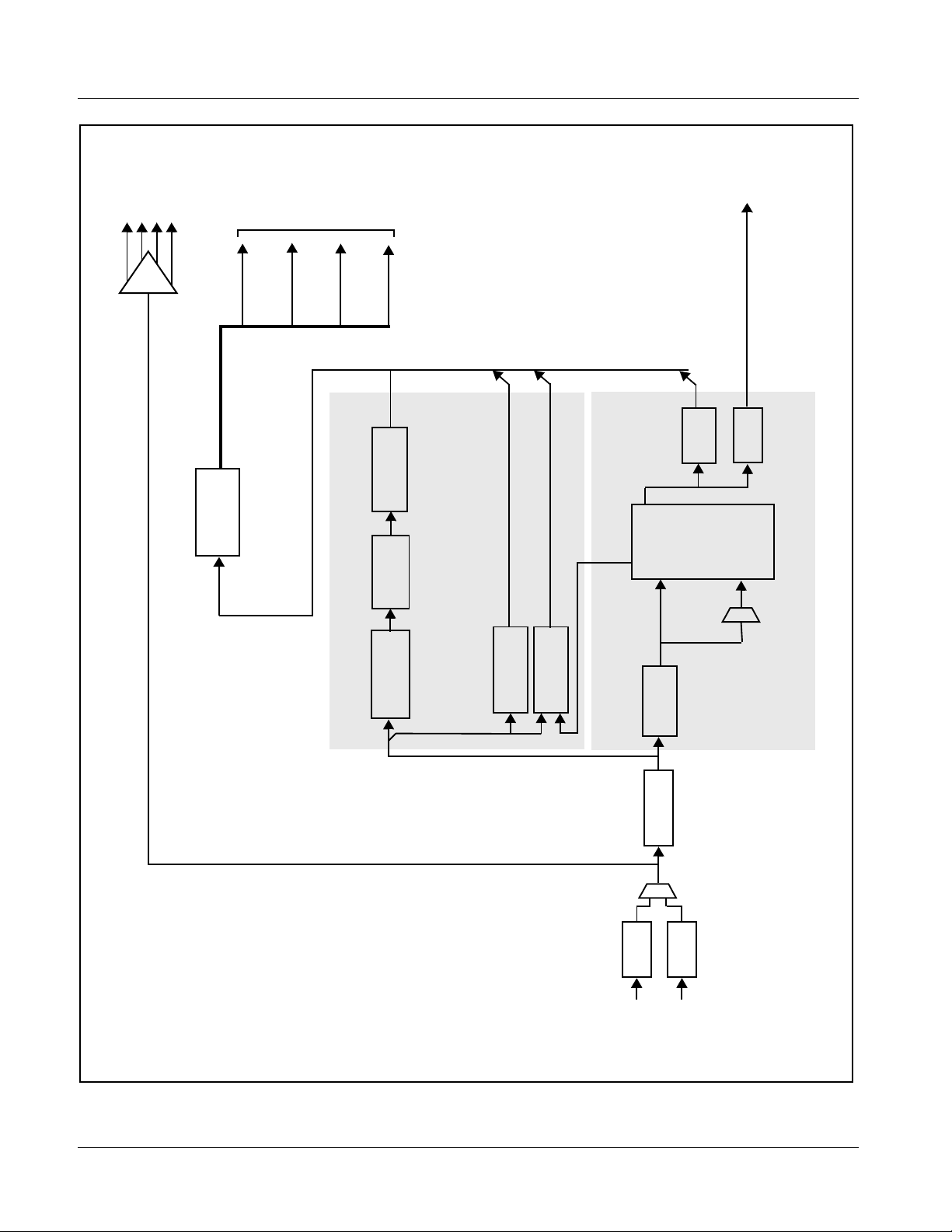
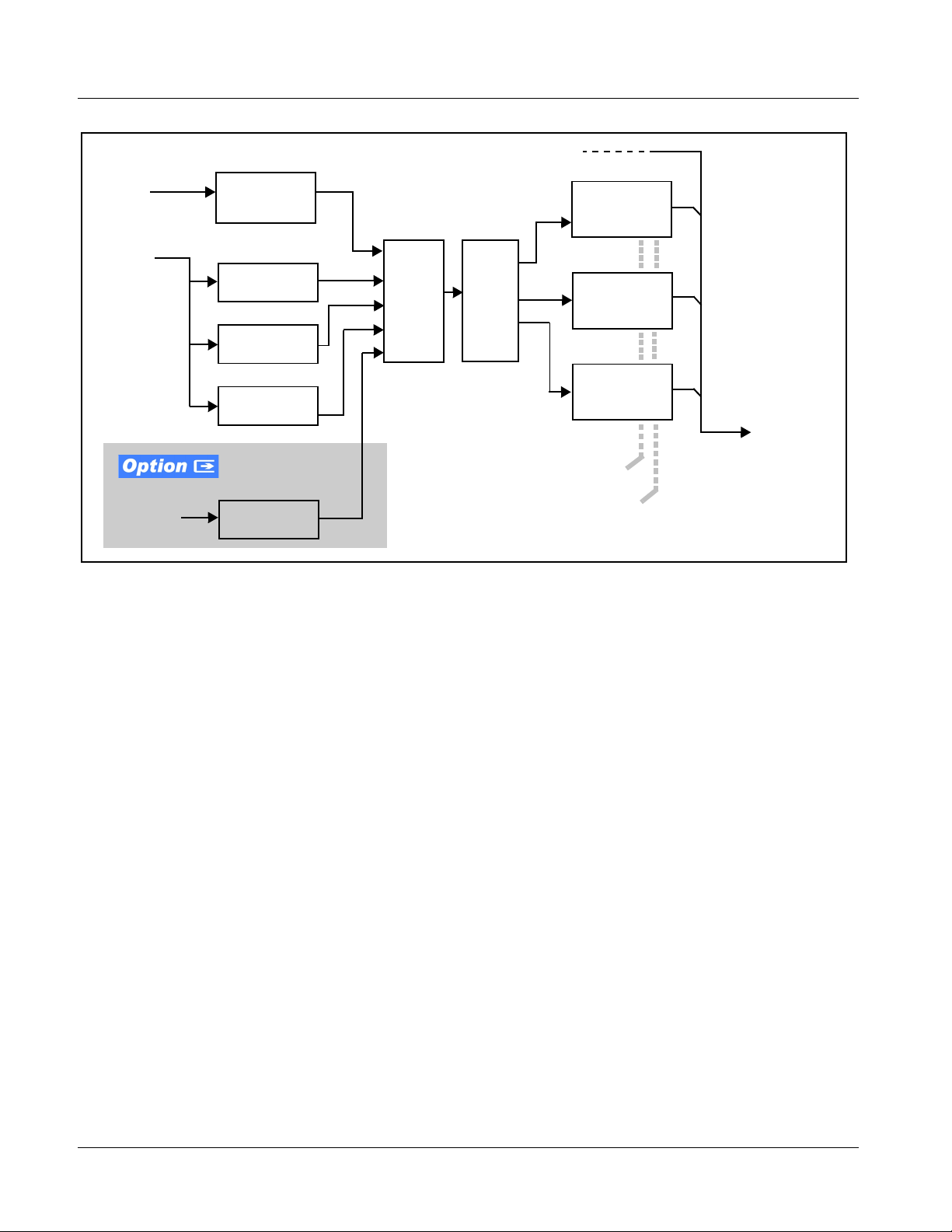
9502-DCDA Functional Description
Figure 1-1 shows a functi onal block diagram of the 9502-DCDA. The
9502-DCDA downconverter also includes embedded audio support and
de-embedding to AES outputs. 4x distribution amplifiers (DAs) are provided
for the card down-converted HD/SD-SDI output.
The 9502-DCDA also provides ARC processing and timecode/
closed-captioning conversion from packet-based timecode formats and
CEA608/708 HD formats to HD ATC, SD_ATC, and SD VITC-based
(waveform) timecode. Closed captioning from CEA708 to HD formats and
line 21 SD closed captioning are available on the processed HD-SD-SDI
outputs.
9502-DCDA Input/Output Formats
The 9502-DCDA provides the following inputs and outputs:
• Inputs:
• 3G/HD/SD SDI IN A / SDI IN B – two dual-rate HD/SD-SDI inputs
(GUI-selectable or basic failover)
• Outputs:
• HD/SD-SDI OUT (1-4) – four dual-rate HD/SD-SDI buffered video
outputs
• RCK OUT (1-4) – four 3G/HD/SD-SDI reclocked buffered video
outputs
• AES OUT (1-8) – eight AES-3id (coaxial 75Ω) outputs (16 AES
channels)
9502DCDA-OM (V1.3) 9502-DCDA PRODUCT MANUAL 1-5
Page 10
1 9502-DCDA Functional Description
3G/HD/SD
RCK OUT
PROCESSED
VIDEO OUT
(HD/SD-SDI)
AES OUT (8 Pair)
supports de-embedding to AES pairs
1 thru 8, current rear module options
support output only to pairs 1 thru 4.
Note: Although card de-embedding
SDI Serializer/
4x DA
Embed
Down
Mixer
Select
Failover Input
AES
Drivers
Audio
/Overlay
ARC/Reticule
Audio
Routing
Video
Processing
Sync Gen
Downconvert/
CEA708/608/VBI
CC
Processing
Video Processor
VBI Waveform/ATC VITC/ATC LTC
TC
Audio LTC
Processing
Audio
Audio Processor
De-Embed
Deserialize
Manual/
EQ/
EQ/
Reclock
Reclock
SDI IN A
3G/HD/SD
SDI IN B
3G/HD/SD
9502BD V1.0LB79
Figure 1-1 9502-DCDA Functional Block Diagram
1-6 9502-DCDA PRODUCT MANUAL 9502DCDA-OM (V1.3)
Page 11

Introduction 9502-DCDA Functional Description
Video Processor Description
The 9502-DCDA features a downconverting scaler, video proc, and
user-adjusta ble aspect ratio cont rol and zo om control. The 9502-DCDA vide o
subsystem also provides the functions described below.
Video Processor
The 9502-DCDA provides full color processing control (luma gain and lift,
chroma saturation, and color phase) of the output video.
Scaler Function
The scaler function provides down-conversion to HD/SD from multiple
standard SD and 3G/HD video formats and multiple frame rates, and
cross-conversion between interlaced and progressive formats, with
auto-format detect/down-conversion of SMPTE 424M/292M/259M formats.
The scaler function also provides aspect ratio conversion that provides a
choice from several st andard aspect ratios. User-defined settings allow
custom user-def ined H and V aspect ratio control. Reticul e i ns ert i on pr ovi des
safe action area marking as well as other reticule functions and patterns.
Timecode Processor
(See Figure 1-2.) This fun ct ion provi de s for ext rac ti on of time code data fro m
the input video, and in turn re-insertion of timecode data into the output SDI.
In this manner, timecode data can be preserved, e ven aft er fo rmat conv ersi on.
The function can monitor the SDI video input of the card for supported
timecode formats and convert the timecode to either or both ATC_LTC or
ATC_VITC for down-conversions to HD, and ATC_VITC or VITC
waveform (with selectable odd/even field line number control) for SD
down-conversions.
When licensed with option
receive and translate audio LTC timecode (from Emb Ch 1-16) for insertion
as SMPTE 12M ATC timecode formats onto the output video as described
above.
+LTC, this function also can
9502DCDA-OM (V1.3) 9502-DCDA PRODUCT MANUAL 1-7
Page 12
1 9502-DCDA Functional Description
HD/SD–SDI
(from scaler)
Frame
Reference
SDI
Video
Input
Audio LTC
(from Emb
Ch 1-16)
Ref VITC
Waveform
Detect/Extract
SDI VITC
Detect/Extract
SDI ATC_VITC
Detect/Extract
SDI ATC_LTC
Detect/Extract
Audio LTC
Select/Extract
Priority/
Select
Buffer/
Format
SDI VITC
Timecode
Proc/Embed
ATC_VITC
Timecode
Proc/Embed
ATC_LTC
Timecode
Proc/Embed
Insert
Control
Line
Number
Control
HD/SD–SDI
Video Output
Figure 1-2 Timecode Processor
Closed Captioning Processor
This function provides support for closed captioning setup. The function
allows the selection of the ancillary data line number where the ancillary
closed caption data is outputted when the output is HD. When receiving
HD-SDI, both CEA 608 and CEA 708 are supported, with CEA 608 and
CEA 708 (containing CEA 608 packets) converted to line 21 closed
captioning on outputs down-converted to SD.
1-8 9502-DCDA PRODUCT MANUAL 9502DCDA-OM (V1.3)
Page 13
Introduction 9502-DCDA Functional Description
Audio Processor Description
The audio processor operates as an internal audio router. This function
chooses from the following inputs:
• 16 channels of embedded audio from the SDI video input (1-to-1
routing to SDI output)
The router function provides the following audio outputs:
• 16 channels of embedded audio on SDI processed outputs
• 16 channels of AES de-embedding on eight AES outputs pairs
Note: Although card de-embedding supports de-embedding to AES pairs 1 thru 8,
current rear module options support output only to pairs 1 thru 4.
The processor function provides group enable/disable and de-embedding of
the 16-channel embedded audio SDI input.
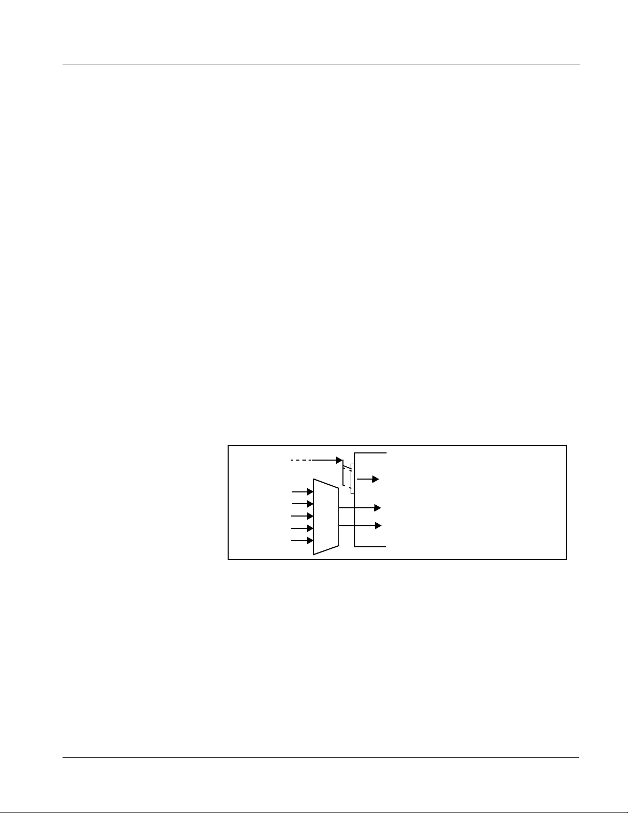
Audio Down Mix Function
(See Figure 1-3.) The Audio Down Mixer function provides for the selection
of any five embedded c hannel s serv ing as Left (
Surround (
into stereo pair Down Mix Left (
resulting stereo pair
Ls), and Right Surround (Rs) individual signals to be multiplexed
DM-L) and Down Mix Right (DM-R). The
DM-L and DM-R can in turn be routed to any embedded
L), Right (R), Center (C), Left
audio pair as desired (or de-embedded to an AES audio output).
Embed Ch 1 - Ch 16
Emb Ch 3
Emb Ch 5
Emb Ch 6
Emb Ch 9
Emb Ch 11
Figure 1-3 Audio Down Mix Functional Block Diagram with Example Sources
L
R
C
Ls
Rs
DM-L
DM-R
9502DCDA-OM (V1.3) 9502-DCDA PRODUCT MANUAL 1-9
Page 14

1 9502-DCDA Functional Description
User Control Interface
Figure 1-4 shows the user control interface options for the 9502-DCDA.
These options are individually described below.
Note: All user control interfaces described here are cross-compatible and can oper-
ate together as desired. Where applicable, any control setting change made
using a particular user interface is reflected on any other connected interface.
• DashB oard™ Us er Interface – Using DashBoard™, the
9502-DCDA and other cards installed in openGear®
1
frames can be
controlled from a computer and monitor.
DashBoard™ allows users to view all frames on a network with
control and monitoring for all populated slots inside a frame. This
simplifies the setup and use of numerous modules in a large
installation and offers the ability to centralize monitoring. Cards
define their controllable parameters to DashBoard™, so the control
interface is always up to date.
The DashBoard™ software can be downloaded from the Cobalt
Digital Inc. website: www.cobaltdigital.com
(enter “DashBoard” in
the search window). The DashBoard™ user interface is described in
Chapter 3,“Operating Instructions”.
• Cobalt
®
OGCP-9000 and OGCP-9000/CC Remote Control
Panels – The OGCP-9000 and OGCP-9000/CC Remote Control
Panels conveniently and intuitively provide parameter monitor and
control of the 9502-DCDA and other video and audio processing
terminal equipment meeting the open-architecture Cobalt
®
cards for
openGear™ standard.
In addition to circumventing the need for a computer to monitor and
control signal processing cards, the Control Panels allow quick and
intuitive access t o hundre ds of cards in a faci lity, and can monitor and
allow adjustment of multiple parameters at one time.
The Remot e Control Pan els are tota lly compatible with the
openGear™ control software DashBoard™; any changes made with
either system are reflected on the other. The Remote Control Panel
user interf ace is descr i bed in Chapter 3,“Operating Instructions”.
1. openGear® is a registered trademark of Ross Video Limited. DashBoard™ is a trademark of Ross
Video Limited.
1-10 9502-DCDA PRODUCT MANUAL 9502DCDA-OM (V1.3)
Page 15
Introduction 9502-DCDA Functional Description
OGCP-9000 Control Panel
OGCP-9000/CC Control Panel
9502-DCDA Card
or
Remote Control Panel
Using the Control Panel,
9502-DCDA card can be remotely
controlled over a LAN
LAN
20-Slot Frame with Network Controller Card
DashBoard™ Remote Control
Using a computer with
DashBoard™ installed,
Computer
with NIC
Note: • To communicate with DashBoard™ or a Remote Control Panel, the frame must have the optional MFC-8320-N network
controller card installed.
• DashBoard™ and the Remote Control Panels provide network control of the 9502-DCDA as shown. The value displayed
at any time on the card, or via DashBoard™ or a Control Panel is the actual value as set on the card, with the current value
displayed being the actual value as effected by the card. Parameter changes made by any of these means are universally
accepted by the card (for example, a change made using the DashBoard™ controls will change the setting displayed on
a Control Panel).
9502-DCDA card can be
remotely controlled over a LAN
In conjunction with a frame equipped
with a Network Controller Card,
9502-DCDA card can be remotely
controlled over a LAN
Figure 1-4 9502-DCDA User Control Interface
Note: If network remote control is to be used for the frame and the frame has not yet
been set up for remote control, Cobalt
®
reference guide Remote Control
User Guide (PN 9000RCS-RM) provides thorough information and
step-by-step instructions for setting up network remote control of Cobalt
cards using DashBoard™. (Cobalt
®
OGCP-9000 and OGCP-9000/CC
Remote Control Panel product manuals have complete instructions for setting
up remote control using a Remote Control Panel.)
Download a copy of this guide by clicking on the Support>Reference
Documents link at www.cobaltdigital.com and then select DashBoard
Remote Control Setup Guide as a download, or contact Cobalt
®
as listed in
Contact Cobalt Digital Inc. (p. 1-15).
®
9502DCDA-OM (V1.3) 9502-DCDA PRODUCT MANUAL 1-11
Page 16
1 Technical Specifications
9502-DCDA Rear I/O Modules
The 9502-DCDA physically inte rfaces to sys tem video connect ions at the rear
of its frame using a Rear I/O Module.
All inputs and outputs shown in the 9502-DCDA Functional Block Diagram
(Figure 1-1) enter and exit the card via the card edge backplane connector.
The Rear I/O Module breaks out the 9502-DCDA card edge connections to
BNC and other connectors that interface with other components and systems
in the signal chain.
The full assortment of 9502-DCDA Rear I/O Modules is shown a nd described
in 9502-DCDA Rear I/O Modules (p. 2-4) in Chapter 2, “Installation and
Setup”.
Technical Specifications
Table 1-1 lists the technical specifications for the 9502-DCDA Up/Down/
Cross Format Converter, Video/Audio In with Frame Sync card.
Table 1-1 Technical Specifications
Item Characteristic
Note: 3G (SMPTE 424M) specifications are applicable for card model 9502-DCDA-3G only.
Part number, nomenclature 9502-DCDA Up/Down/Cross For mat Conver ter, Video/Audio In
with Frame Sync
Installation/usage environment Intended for installation and usage in frame meeting openGear™
modular system definition.
Power consumption < 18 Watts maximum
Installation Density Up to 20 cards per 20-slot frame
Environmental:
Operating temperature:
Relative humidity (operating or storage):
Frame communication 10/100 Mbps Ethernet with Auto-MDIX.
Indicators Card edge display and indicators as follows:
32° – 104° F (0° – 40° C)
< 95%, non-condensing
• 4-character alphanumeric display
• Status/Error LED indicator
• Input Format LED indicator
1-12 9502-DCDA PRODUCT MANUAL 9502DCDA-OM (V1.3)
Page 17

Introduction Technical Specifications
Table 1-1 Technical Specifications — continued
Item Characteristic
Serial Digital Video Input Number of inputs:
Two, with manual select or failover to card processing path
Data Rates Supported:
SMPTE 424M, 292M, SMPTE 259M-C
Impedance:
75 Ω terminating
Return Loss:
> 15 dB up to 1.485 GHz
> 10 dB up to 2.970 GHz
Post-Processor Serial Digital Video
Outputs
Pre-Processor (Reclocked) Serial Digital
Video Outputs
AES Audio Outputs Standard:
Number of Outputs:
Four 3G/HD/SD-SDI BNC
Impedance:
75 Ω
Return Loss:
> 15 dB at 5 MHz – 270 MHz
Signal Level:
800 mV ± 10%
DC Offset:
0 V ± 50 mV
Jitter (SD ) :
< 0.2 UI (all outputs)
Overshoot:
< 0.2% of amplitude
Number of Outputs:
Four 3G/HD/SD-SDI BNC per IEC 60169-8 Amendment 2
Impedance:
75 Ω
SMPTE 276M
Number of Outputs:
4 unbalanced (8-ch); AES-3id
Output Impedance:
75 Ω
9502DCDA-OM (V1.3) 9502-DCDA PRODUCT MANUAL 1-13
Page 18

1 Warranty and Service Information
Warranty and Service Information
Cobalt Digital Inc. Limited Warranty
This product is warranted to be free from defects in material and workmanship for a period of five (5)
years from the date of shipment to the original purchaser, except that 4000, 5000, 6000, 8000 series
power supplies, and Dolby
material and workmanship for a period of one (1) year.
Cobalt Digital Inc. 's (“Cobalt”) sole obligation under this warranty shall be limited to, at its option, (i)
the repair or (ii) replacement of the product, and the determinati on of whether a defect is covered under
this limited warranty shall be made at the sole discretion of Cobalt.
This limited warranty applies onl y to the original end- purchaser of the produc t, and is not assignable or
transferrable therefrom. This warranty is limited to defects i n material a nd workman shi p, and shal l not
apply to acts of God, accidents, or negligence on behalf of the purchaser, and shall be voided upon the
misuse, abuse, alteration, or modification of the product. Only Cobalt authorized factory
representatives are authorized to make repairs to the product, and any unauthorized attempt to repair
this product shall immediately void the warranty. Please contact Cobalt Technical Support for more
information.
®
modules (where applicable) are warranted to be free from defects in
To facilitate the resolution of warranty related issues , Cobalt recommends registering the product by
completing and returning a product registration form. In the event of a warrantable defect, the
purchaser shall notify Cobalt with a description of the problem, and Cobalt shall provide the purchaser
with a Return Material Authorization (“RMA”). For return, defective prod ucts should be double boxed,
and sufficiently protected, in the original packaging, or equivalent, and shipped to the Cobalt Factory
Service Center, postage prepaid and insured for the purchase price. The purchaser should include the
RMA number, description of the problem encountered, date purchased, name of dealer purchased
from, and serial number with the shipment.
Cobalt Digital Inc. Factory Service Center
2406 E. University Avenue Office: (217) 344-1243
Urbana, IL 61802 USA Fax: (217) 344-1245
www.cobaltdigital.com Email: info@cobaltdigital.com
THIS LIMITED WARRANTY IS EXPRESSLY IN LIEU OF ALL OTHER WARRANTIES
EXPRESSED OR IMPLIED, INCLUDING THE WARRANTIES OF MERCHANTABILITY AND
FITNESS FOR A PARTICULAR PURPOSE AND OF ALL OTHER OBLIGATIONS OR
LIABILITIES ON COBALT'S PART. ANY SOFTWARE PROVIDED WITH, OR FOR USE WITH,
THE PRODUCT IS PROVIDED “AS IS.” THE BUYER OF THE PRODUCT ACK NOWLEDGES
THAT NO OTHER RE PRESENTATIONS WERE MADE OR RELIED UPON WIT H RESPECT TO
THE QUALITY AND FUNCTION OF THE GOODS HEREIN SOLD. COBALT PRODUCTS ARE
NOT AUTHORIZED FOR USE IN LIFE SUP PORT APPLICATIONS.
COBALT'S LIABILITY, WHETHER IN CONTRACT, TORT, WARRANTY, OR OTHERWISE, IS
LIMITED TO THE REPAIR OR REPLACEMENT, AT ITS OPTION, OF ANY DEFECTIVE
PRODUCT, AND SHALL IN NO EVENT INCLUDE SPECIAL, INDIRECT, INCIDENTAL, OR
CONSEQUENTIAL DAMAGES (INCL UDING LOST PROFITS), EVEN IF IT HAS BEEN
ADVISED OF THE POSSIBILITY OF SUCH DAMAGES.
1-14 9502-DCDA PRODUCT MANUAL 9502DCDA-OM (V1.3)
Page 19

Introduction Contact Cobalt Digital Inc.
Contact Cobalt Digital Inc.
Feel free to contact ou r th oro ugh and professional support representatives for
any of the following:
• Name and address of your local dealer
• Product information and pricing
• Technical support
• Upcomin g trade show informatio n
Phone: (217) 344-1243
Fax: (217) 344-1245
Web: www.cobaltdigital.com
General Information: info@cobaltdigital.com
Technical Support: support@cobaltdigital.com
9502DCDA-OM (V1.3) 9502-DCDA PRODUCT MANUAL 1-15
Page 20

This page intentionally blank
1-16 9502-DCDA PRODUCT MANUAL 9502DCDA-OM (V1.3)
Page 21

Chapter 2 Installation and Setup
Overview
This chapter contains the following information:
• Installing the 9502-DCDA Into a Frame Slot (p. 2-1)
• Installing a Rear I/O Module (p. 2-3)
• Setting Up 9502-DCDA Network Remote Control (p. 2-6)
Installing the 9502-DCDA Into a Frame Slot
CAUTION
Heat and power distribution requirements within a frame may dictate specific
slot placement of cards. Cards with many heat-producing compon ents should
be arranged to avoid areas of excess heat build-up, particularly in frames
using only convection cooling. The 9502-DCDA has a moderate power
dissipation (<18 W). As such, avoiding placing the card adjacent to other
cards with similar dissipation values if possible.
Chapter 2
CAUTION
This device contains semiconductor devices which are
susceptible to serious damage from Electrostatic
Discharge (ESD). ESD damage may not be immediately
apparent and can affect the long-term reliability of the
device.
Avoid handling circuit boards in high static environments
such as carpeted areas, and when wearing synthetic fiber
clothing. Always use proper ESD handling precautions
and equipment when working on circuit boards and
related equipment.
Note: If installing the 9502-DCDA in a slot with no rear I/O module, a Rear I/O
Module is required before cabling can be connected. Refer to Installing a
Rear I/O Module (p. 2-3) for rear I/O module installation procedure.
CAUTION
If required, make certain Rear I/O Module(s) is installed before installing the
9502-DCDA into the frame slot. Damage to card and/or Rear I/O Module can
occur if module installation is attempted with card already installed in slot.
9502DCDA-OM (V1.3) 9502-DCDA PRODUCT MANUAL 2-1
Page 22

2 Installing the 9502-DCDA Into a Frame Slot
Note: Check the packaging in which the 9502-DCDA was shipped for any extra
items such as a Rear I/O Module connection label. In some cases, this label
is shipped with the card and to be installed on the Rear I/O connector bank
corresponding to the slot location of the card.
Install the 9502-DCDA into a frame slot as follows:
1. Determine the slot in which the 9502-DCDA is to be installed.
2. Open the frame front access panel.
3. While holding the card by the card edges, align the card such that the
plastic ejector tab is on the bottom.
4. Align the card with the top and bottom guides of the slot in which the
card is being installed.
5. Gradually slide the card into the slot. When resistance is noticed, g ently
continue pushing the card until its rear printed circuit edge terminals
engage fully into the rear I/O module mating connector.
CAUTION
If card resists fully engaging in rear I/O module mating connector, check for
alignment and proper insertion in slot tracks. Damage to card and/or rear I/O
module may occur if improper card insertion is attempted.
Verify that the card is fully engaged in rear I/O module mating
6.
connector.
7. Close the frame front access panel.
8. Connect the input and output cables as shown in 9502-DCDA Rear I/O
Modules (p. 2-4).
9. Repeat steps 1 through 8 for other 9502-DCDA cards.
Note: The 9502-DCDA BNC inputs are internally 75-ohm terminated. It is not neces-
sary to terminate unused BNC inputs or outputs.
Note: To remove a card, press down on the ejector tab to unseat the card from the
rear I/O module mating connector. Evenly draw the card from its slot.
10. I f network remote control is to be used for the fram e and the frame has
not yet been set up for remote contro l, pe rf orm set up in accordance with
Setting Up 9502-DCDA Network Remote Control (p. 2-6).
Note: If installing a card in a frame already equipped for, and connected to
DashBoard™, no network setup is required for the card. The card will be discovered by DashBo ard™ and be ready for use.
2-2 9502-DCDA PRODUCT MANUAL 9502DCDA-OM (V1.3)
Page 23

Installation and Setup Installing a Rear I/O Module
Installing a Rear I/O Module
Note: This procedure is applicable only if a Rear I/O Module is not currently
installed in the slot where the 9502-DCDA is to be installed.
If installing the 9502-DCDA in a slot already equipped with a suitable I/O
module, omit this procedure.
Install a Rear I/O Module as follows:
1. On the frame, determine the slot in which the 9502-DCDA is to be
installed.
2. In the mounting area corresponding to the slot location, install
Rear I/O Module as shown in Figure 2-1.
Align and engage mounting tab on Rear
I/O Module with the module seating slot
1
on rear of frame chassis.
DSCN3483A.JPG
Hold top of Rear I/O Module flush against
frame chassis and start the captive screw.
2
Lightly tighten captive screw.
DSCN3487A.JPG
Figure 2-1 Rear I/O Module Installation
9502DCDA-OM (V1.3) 9502-DCDA PRODUCT MANUAL 2-3
Page 24

2 Installing a Rear I/O Module
9502-DCDA Rear I/O Modules
Table 2-1 shows and describes the full assortment of Rear I/O Modules
specifically for use with the 9502-DCDA.
Notes: • Rear I/O Modules equipped with 3-wire Phoenix connectors are supplied
with removable screw terminal block adapters. For clarity, the adapters are
omitted in the drawings below.
Table 2-1 9502-DCDA Rear I/O Modules
9502-DCDA Rear I/O Module Description
RM20-9502-A Provides the following conne cti on s:
• Two 3G/HD/SD-SDI coaxial input (SDI IN A and
SDI IN B)
• Four reclocked SDI input copies (RCK OUT 1 thru
RCK OUT 4)
• Four processed coaxial outputs (SDI OUT 1 thru
SDI OUT 4)
RM20-9502-A/S Split Rear Module. Provides each of the following
connections for two 9502 cards:
• 3G/HD/SD-SDI coaxial input (SDI IN A)
• Two reclocked SDI input copies (RCK OUT 1 and
RCK OUT 2)
• Two processed coaxial outputs (SDI OUT 1 and
SDI OUT 2)
2-4 9502-DCDA PRODUCT MANUAL 9502DCDA-OM (V1.3)
Page 25

Installation and Setup Installing a Rear I/O Module
Table 2-1 9502-DCDA Rear I/O Mod ules — continued
9502-DCDA Rear I/O Module Description
RM20-9502-F Provides the following connections:
• Two 3G/HD/SD-SDI coaxial input (SDI IN A and
SDI IN B)
• Four AES coaxial audio outputs (AES OUT 1 thru
AES OUT 4)
• Four processed coaxial outputs (SDI OUT 1 thru
SDI OUT 4)
Note: Although card de-embedding supports
de-embedding to AES pairs 1 thru 8, current rear
module options support output only to pairs
1 thru 4.
RM20-9502-C/S Split Rear Module. Provides each of the following
connections for two 9502 cards:
• Two 3G/HD/SD-SDI coaxial input (SDI IN A and
SDI IN B)
• Four reclocked SDI input copies (RCK OUT 1 thru
RCK OUT 4)
• Four processed coaxial outputs (SDI OUT 1 thru
SDI OUT 4)
Note: Available equipped with High-Density BNC
(HDBNC) or DIN1.0/2.3 connectors as:
RM20-9502-C/S-HDBNC or RM20-9502-C/S-DIN,
respectively.
9502DCDA-OM (V1.3) 9502-DCDA PRODUCT MANUAL 2-5
Page 26

2 Setting Up 9502-DCDA Network Remote Control
Setting Up 9502-DCDA Network Remote Control
Perform remote control setup in accordance with Cobalt® reference guide
“Remote Control User Guide” (PN 9000RCS-RM).
Note: • If network remote control is to be used for the frame and the frame has not
yet been set up for remote control, Cobalt
Control User Guide (PN 9000RCS-RM) provides thorough information and
step-by-step instructions for setting up network remote control of Cobalt
cards using DashBoard™. (Cobalt
Remote Control Panel product manuals have complete instructions for
setting up remote control using a Remote Control Panel.)
Download a copy of this guide by clicking on the
Support>Reference Documents link at www.cobaltdigital.com and then
select DashBoard Remote Control Setup Guide as a download, or contact
®
Cobalt
• If installing a card in a frame already equipped for, and connected to
DashBoard™, no network setup is required for the card. The card will be discovered by DashBoard™ and be ready for use.
as listed in Contact Cobalt Digital Inc. (p. 1-15).
®
®
reference guide Remote
OGCP-9000 and OGCP-9000/CC
®
2-6 9502-DCDA PRODUCT MANUAL 9502DCDA-OM (V1.3)
Page 27

Overview
Chapter 3
Chapter 3 Operating Instructions
This chapter contains the following information:
If you are already familiar
with using DashBoard or a
Cobalt Remote Control
Panel to control Cobalt
cards, please skip to
9502-DCDA Function
Submenu List and
Descriptions (p. 3-9).
• Control and Display Descriptions (p. 3-1)
• Accessing the 9502-DCDA Card via Remote Control (p. 3-5)
• Checking 9502-DCDA Card Information (p. 3-7)
• Ancillary Data Line Number Locations and Ranges (p. 3-8)
• 9502-DCDA Function Submenu List and Descriptions (p. 3-9)
• Troubleshooting (p. 3-28)
Control and Display Descriptions
This secti on describes the user interface controls, indicators, and displays for
using the 9502-DCDA card. The 9502-DCDA functions can be accessed and
controlled using any of the user interfaces described here.
The format in which the 9502-DCDA functional controls, indicators, and
displays appear and are used varies depending on the user interface being
used. Regardless of the user interface being used, access to the 9502-DCDA
functions (and the controls, indicators, and displays related to a particular
function) follows a general arrangement of Function Submenus under which
related controls can be accessed (as described in Function Submenu/
Parameter Submenu Overview below).
Note: When a setting is changed, settings displayed on DashBoard™ (or a Remote
Control Panel) are the settings as effected by the card itself and reported back
to the remote control; the value displayed at any time is the actual value as set
on the card.
9502DCDA-OM (V1.3) 9502-DCDA PRODUCT MANUAL 3-1
Page 28
3 Control and Display Descriptions
Function Submenu/Parameter Submenu Overview
The functions and related parameters available on the 9502-DCDA card are
organized into function submenus, which consist of parameter groups as
shown below.
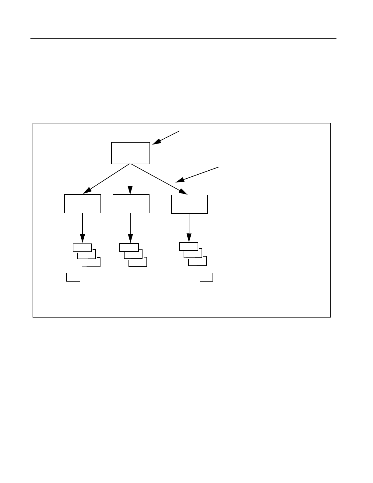
Figure 3-1 shows how the 9502-DCDA card and its submenus are organized,
and also provides a n overvie w of how na vigation is perfo rmed between cards,
function submenus, and parame ters.
If using DashBoard™ or a Remote Control Panel, the
desired 9502-DCDA card is first selected.
9502-DCDA
Submenu a Submenu b
Individual Parameters
Each submenu consists of groups of parameters
related to the function submenu. Using the “Proc
Control” function submenu example, the individual
parameters for this function consist of various v ideo
processor parameters such as Gain, Lift, Saturation,
and so on.
Figure 3-1 Function Submenu/Parameter Submenu Overvie w
• • •
The desired function submenu is next
selected.
Function Submenus consist of parameter
groups related to a particular 9502-DCDA
card function (for example, “Proc Control”).
Submenu z
3-2 9502-DCDA PRODUCT MANUAL 9502DCDA-OM (V1.3)
Page 29

Operating Instructions Control and Display Descriptions
DashBoard™ User Interface
(See Figure 3-2.) The card function submenus are organized in DashBoard™
using tabs. When a tab is selected, each parametric control or selection list
item associated with the function is displayed. Scalar (numeric) parametric
values can then be adjusted as desired using the GUI slider controls. Items in
a list can then be selected using GUI drop-down lists.
Typical Button Control s Typical Status Displ a y
DashBoard Tabs
Typical Parametric ControlTypical Selection List
Figure 3-2 Typical DashBoard Tabs and Controls
9502DCDA-OM (V1.3) 9502-DCDA PRODUCT MANUAL 3-3
Page 30

3 Control and Display Descriptions
Cobalt® Remote Control Panel User Interfaces
(See Figure 3-3.) Similar to the function submenu tabs using DashBoard™,
the Remote Control Panels have a Select Submenu key that is used to display
a list of function submenus. From this list, a control knob on the Control
Panel is used to select a function from the list of displayed function submenu
items.
When the desired function submenu is selected, each parametric control or
selection list item associated with the function is displayed. Scalar (numeric)
parametric values can then be adjusted as desired using the control knobs,
which act like a potentiometer. Items in a list can then be selected using the
control knobs which cor respo ndingl y act li ke a r otary switch . (In t his man ner,
the setting effected using controls and select ion lists displayed on the Control
Panel are comparable to t he submenu i tems acce ssed and committed u sing the
9502-DCDA card edge controls.)
Figure 3-3 shows accessing a function submenu and its parameters (in this
example, “Video Proc”) using the Control Panel as compared to using the
card edge controls.
Video Proc function
(among others) is
accessed using the Control
Panel Select Submenu
key. Video Proc function is
selected from the list of
functions (submenu items)
When the Video Proc
function submenu is
selected, its related
parameters are now
displayed.
Note: Refer to “OGCP-9000 Remote Control Panel User Manual” (PN
OGCP-9000-OM) or “OGCP-9000/CC Remote Control Panel User Manual”
(PN OGCP-9000/CC-OM) for complete instructions on using the Control Panels.
3396B_3346B.JPG
In this example, Color Gain
(saturation) is adjusted using
the control knob adjacent to
Color Gain
Figure 3-3 Remote Control Panel Setup of Example Video Proc Function Setup
9502-DCDA_3370_3372B.
3-4 9502-DCDA PRODUCT MANUAL 9502DCDA-OM (V1.3)
Page 31

Operating Instructions Accessing the 9502-DCDA Card via Remote Control
Accessing the 9502-DCDA Card via Remote Control
Access the 9502-DCDA card using DashBoa rd™ or Cobalt® Remote Control
Panel as described below.
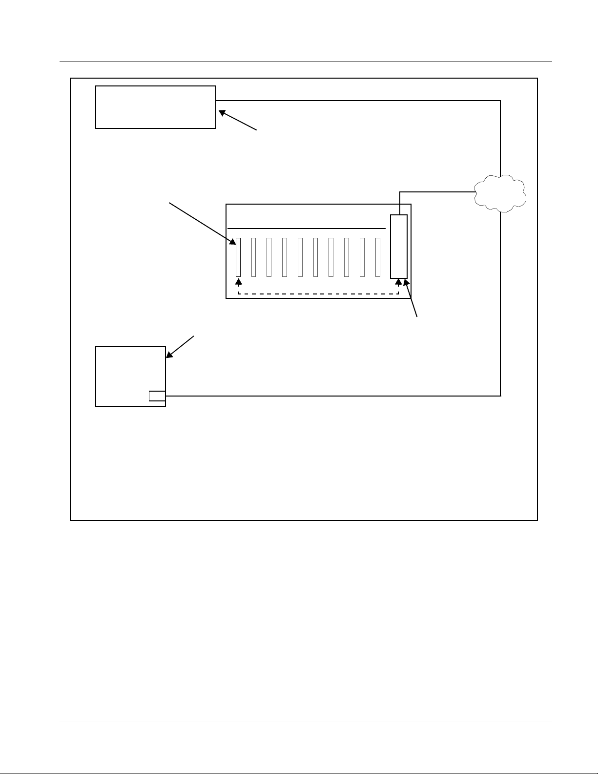
Accessing the 9502-DCDA Card Using DashBoard™
1. On the computer connected to the frame LAN, open DashBoard™.
2. As shown be low, in the left side Basic View Tree locate the Network
Controller Card associated with the frame containing the 9502-DCDA
card to be accessed (in this example, “MFC-8320-N SN: 00108053”).
3. As shown below, expand the tree to access the cards within the frame.
Click on the card to be accessed (in this example, “Slot 6: 9502-DCDA”).
.
As shown on the next page, when the card is accessed in DashBoard™
its function submenu scree n showing ta bs for eac h functi on is disp layed.
(The particular submenu screen displayed is the previously displayed
screen from the last time the card was accessed by DashBoard™).
9502DCDA-OM (V1.3) 9502-DCDA PRODUCT MANUAL 3-5
Page 32

3 Accessing the 9502-DCDA Card via Remote Control
Card Access/Navigation
Tree Pane
Card Info
Pane
Card Function Submenu
and Controls Pane
Accessing the 9502-DCDA Card Using a Cobalt® Remote Control Panel
Press the Select Device key and select a c ard as shown in the example below.
This display shows the list
order number of the device that
is ready for selection
3-6 9502-DCDA PRODUCT MANUAL 9502DCDA-OM (V1.3)
This display shows the devices assigned to the Control Panel.
• Rotate any knob to select from the list of devices. The device selected
using a knob is displayed with a reversed background (in this example,
“1 9502-DCDA - Receiver 21 Input Processing”).
• Directly enter a device by entering its list number using the numeric
keypad, and then pressing Enter or pressing in any knob).
Page 33

Operating Instructions Checking 9502-DCDA Card Information
Checking 9502-DCDA Card Information
The operating status and software version the 9502-DCDA card can be
checked using DashBoard™ or the card edge control user interface. Figure
3-4 shows and describes the 9502-DCDA card information screen using
DashBoard™ and accessing c ard info rmation using th e card ed ge cont rol user
interface.
Note: Proper operating status in DashBoard™ is denoted by green icons for the sta-
tus indicators shown in Figure 3-4. Yellow or red icons respectively indicate
an alert or failure condition. Refer to Troubleshooting (p. 3-28) for corrective
action.
The Tree View shows the cards seen by DashBoard™.
In this example, Network Controller Card is hosting a
9502-DCDA card in slot 4.
Status Display
This displays shows the status and format of the signals being
received by the 9502-DCDA, as well as card status.
Card Info Dis p la y
This displays (alternately selected in the Card Info pane) shows
the the card hardware and software version info, as well as a
Cobalt code number for the currently installed rear module.
Figure 3-4 9502-DCDA Card Info/Status Utility
9502DCDA-OM (V1.3) 9502-DCDA PRODUCT MANUAL 3-7
Page 34

3 Ancillary Data Line Number Locations and Ranges
Ancillary Data Line Number Locations and Ranges
Table 3-1 lists typical default output video VANC line number locations for
various ancillary data items that may be passed or handled by the card.
Table 3-1 Typical Ancillary Data Line Number Locations/Ranges
Default Line No. / Range
Item
SD HD
AFD 12 (Note 2) 9 (Note 2)
ATC_VITC 13 (Note 2) 9/8 (Note 2)
ATC_LTC — 10 (Note 2)
®
Dolby
Metadata 13 (Note 2) 13 (Note 2)
SDI VITC Waveform 14/16 (Note 2) —
Closed Captioning 21 (locked) 10 (Note 2)
Notes:
1. The card does not check for conflicts on a given line number. Make certain the selected line is available
and carrying no other data.
2. While range indicated b y d rop -dow n li st o n G UI m ay al lo w a particular range of choices, the act ual ran ge
is automatically cl amped (limi ted) to c ert ain rang es to preven t inadv ertent con fli ct with a ctive pictu re ar ea
depending on video format. Limiting ranges for various output formats are as follows:
Format Line No. Limiting Format Line No. Limiting Format Line No. Limiting
525i 12-19 720p 9-25 1080p 9-41
625i 9-22 1080i 9-20
Because line number allocation is not standardized for all ancillary items,
consideration should be given to all items when performing set-ups. Figure
3-5 shows an example of improper and corrected VANC allocation within an
HD-SDI stream.
ATC_VITC = 9/8
CC = 10
Dolby Meta data = 13
Card 1
ATC_VITC = 9/ 8
CC = 10
Dolby Metadata = 13
Card 1
AFD Insertion
attempted usin g
VANC line 9
(default)
AFD Insertion
corrected to us e
VANC line 18
ATC_VITC = 9/8
AFD = 9
CC = 10
Dolby Meta data = 13
Card n
ATC_VITC = 9/8
CC = 10
Dolby Metadata = 13
AFD = 18
Card n
Conflict between
ATC_VITC and AFD both
on VANC line 9
Conflict between
ATC_VITC on line 9/8 and
AFD (now on line 18)
resolved
Figure 3-5 Example VANC Line Number Allocation Example
3-8 9502-DCDA PRODUCT MANUAL 9502DCDA-OM (V1.3)
Page 35

Operating Instructions 9502-DCDA Function Submenu List and Descriptions
9502-DCDA Function Submenu List and Descriptions
Table 3-2 individually lists and describes each 9502-DCDA function
submenu and its related list selections, controls, and parameters. Where
helpful, examples showi ng usage of a function are also provided. Table 3-2 is
primarily based upon using DashBoard™ to access each function and its
corresponding submenus and parameters.
Note: All numeric (scalar) parameters displayed on DashBoard™ can be changed
using the slider controls, arrows, or by numeric keypad entry in the corresponding numeric field. (When using numeric keypad entry, add a return after
the entry to commit the entry.)
Note: 3G inputs, controls, and functions described in this section are not applicable
to 9502-DCDA-HD. In all other aspects, this version function identically as
described.
On DashBoard™ itself and in Table 3-2, the function submenu items are
organized using tabs as shown below.
Some functions use sub-tabs to help maintain clarity and organization. In these instances,
Table 3-2 shows the ordinate tab along with its sub-tabs. Highlighted sub-tabs indicate that
controls described are found by selecting this sub-tab (in this example, the Downmixer
sub-tab on the Audio Control page).
The table below provides a quick-reference to the page numbers where each
function submenu item can be found.
Function Submenu Item Page Function Submenu Item Page
Input Video Controls 3-10 Closed Captioning 3-19
Scaler 3-10 Reticules 3-20
Video Alignment 3-12 Output Audio Routing/Controls 3-23
Timecode 3-13 Presets/Card Fir mware Upgrad e 3-26
Video Payload ID 3-17 Log Status/Download 3-27
Proc (Video) Control 3-18
9502DCDA-OM (V1.3) 9502-DCDA PRODUCT MANUAL 3-9
Page 36

3 9502-DCDA Function Submenu List and Descriptions
Table 3-2 9502-DCDA Function Submenu List
Allows manual or failover selection of card SDI inputs
and displays status, raster format, and embedded
Input Video Controls
group status of received SDI video.
• Input Video Source Selects the input video source to be applied to the card’s program video
• Input Video Status Displays input status and audio group presence, along with elapsed time
input.
• SDI A and SDI B choices allow forced manual selection of
correspondingly SDI IN A or SDI IN B.
• Failover A to B sets main path preference of SDI IN A.
- If SDI IN A goes invalid, then SDI IN B is sele cted.
- If SDI IN A goes valid again, failover automatically reverts to
SDI IN A.
• Failover B to A sets main path preference of SDI IN B.
- If SDI IN B goes invalid, then SDI IN A is sele cted.
- If SDI IN B goes valid again, failover automatically reverts to
SDI IN B.
Note: Failover criteria is simple signal presence.
of signal acquire.
SDI A and SDI B Status show
raster/format for both card inputs. If
signal is not present or is invalid,
Unlocked is displayed. (These
status indications are also
propagated to the Card Info pane.)
Presence of each embedded audio
group is also displayed for actively
selected input.
Provides aspect ratio controls and user H/V controls.
Scaler
• Input/Output Video Status Displays signal format/status sent to scaler (as a function of Input Video
• Downconverter Controls 9502-DCDA provides selectable down-conversion for 3G, HD and SD
Source settings above), as well as output format/status.
If invalid or no signal is present, none is displayed.
inputs with the choices as shown using the controls here.
Selected settings will automatically engage when corresponding video
input format is received by the card.
3-10 9502-DCDA PRODUCT MANUAL 9502DCDA-OM (V1.3)
Page 37

Operating Instructions 9502-DCDA Function Submenu List and Descriptions
Table 3-2 9502-DCDA Function Submenu List — continued
(continued)
• ARC Select Controls Selects between the standard preset Aspect Ratio Conversions (ARC)
• H Pan and V Pan Controls H Pan control shifts horizontal center of image left (negative settings) or
shown here, as well as User Defined Settings.
Buttons allow standard ARC presets
to be applied to output video. For any
setting, using the Horizontal or
Vertical controls allow user custom
settings.
Pressing any of the preset buttons
restores the ARC to the selected
setting and overrides any previous
custom settings.
(50% to 150% user range in 0.1%
steps; null = 100.0)
right (positive settings)
(-74% to 74% range in 0.1% steps; null = 0.0)
-74 0 74
V Pan control shifts vertical center of image down (negative settings) or
up (positive settings)
(-74% to 74% range in 0.1% steps; null = 0.0)
-74
0
74
9502DCDA-OM (V1.3) 9502-DCDA PRODUCT MANUAL 3-11
Page 38

3 9502-DCDA Function Submenu List and Descriptions
Table 3-2 9502-DCDA Function Submenu List — conti nued
Shows the card output video alignment relative to
selected video or reference sources.
Video Alignment
This allows assessment of the card’s video timing/sync
relative to other video or house reference sources.
• Reference Relative-To Select Selects the timing source to which the card’s output video is measured
• Alignment Timing Display Shows (in near real-time msec) the offset between the card’s out put video
against (in example here, card output video is measured relative to frame
Reference 1).
timing and the selected reference source.
Examples: With source set to Input Video, the c ard’s static latent delay is
shown. With Reference 1 selected, a slow drift indicates the card’s input is
not upstream frame synced or ref locked with this reference. A non-drifting
display would indicate that upstream video is ref locked to the selected
reference.
3-12 9502-DCDA PRODUCT MANUAL 9502DCDA-OM (V1.3)
Page 39

Operating Instructions 9502-DCDA Function Submenu List and Descriptions
Table 3-2 9502-DCDA Function Submenu List — continued
Provides timecode data extract ion from va rious
sources, and provides formatting and re-insertion
Timecode
Shown below is an example in which received 1080i 5994 SDI video is being down-converted to 525i 5994. To preserve and
re-insert the timecode data after scaling (which removes timecode packets), timecode re-insertion is performed using the
Timecode controls. Each Timecode control is fully described on the pages that follow.
controls for inserting the timecode into the output video.
1080i 5994
w/ ATC_LTC
A
Noting that the incoming video contains ATC_LTC
9502
525i5994
w/ ATC_VITC
w/ VITC waveform
timecode data (as shown in the status display), set the
Source Priority drop-down lists to include ATC_LTC
timecode data as a choice. This extracts ATC_LTC
timecode data from the incoming video to allow for
re-insertion as a selected format.
In this example, it is desired to provide both SDI
B
ATC_VITC and VITC waveform timecode data in the
converted SD output video. As such, set both
SD ATC VITC Insertion and SD VITC Waveform
Insertion to Enabled.
In the example here, the line numbers are set to the
default SMPTE 12M-2-2008 recommended values.
Reference VITC
Detect/Extract
1080i SDI
w/ ATC_LTC
SDI VITC
Detect/Extract
A
Priority/
Select
Buffer/
Format
SDI VITC
Timecode
Proc/Embed
ATC_VITC
Timecode
Proc/Embed
B
B
SDI ATC_VITC
Detect/Extract
ATC_LTC
Line
Timecode
Proc/Embed
525i SDI
w/ATC_VITC
w/VITC wavewform
SDI ATC_LTC
Detect/Extract
Audio LTC
Detect/Extract
9502DCDA-OM (V1.3) 9502-DCDA PRODUCT MANUAL 3-13
A
Insert
Control
Number
Control
Page 40

3 9502-DCDA Function Submenu List and Descriptions
Table 3-2 9502-DCDA Function Submenu List — conti nued
(continued)
allows audio LTC from an embedded audio channel to be used as a timecode source, with conversion to a selected SMPTE 12M
format on the output video.
• Timecode Source Status Displays Displays the current status and contents of the received timecode formats
• Audio LTC Source and Mute Controls
Audio LTC controls described below only appear on cards with +LTC licensed optional feature. This feature
shown to the left.
• If a format is receiving timecode data, the current content (timecode
running count) is displayed.
• I f a format is not receiving timecode data, Not Present is displayed.
(+LTC option only)
L TC Input control selects input embedded audio channel when audio L TC
is to be used as a source.
Mute LTC Audio control allows timecode using LTC audio sources to
freeze as follows:
• W hen set to Enabled and input timecode is lost, timecode insertion is
disabled.
• W hen set to Disabled and input timecode is lost, timecode output
reverts to free-run.
Note: If muting upon loss of a particular input format is desired, set all
Source Priority 1 thru 4 to that particular input format. If this is not done,
the card failover timecode selection may substitute another format choice
for the format not being received.
• Incoming ATC Packet Removal Control Enables or disables removal of existing input video ATC timecode packets
• Timecode Master Insertion Control
from the output. This allows removal of undesired existing timecodes from
the output, resulting in a “clean slate” where only desired timecodes are
then re-inserted into the output. (For example, if both SDI ATC_VITC and
ATC_LTC are present on the input video, and only AT C_LTC is desired,
using the Removal control will remove both timecodes from the output.
The ATC_LTC timecode by itself can then be re-inserted on the output
using the other controls discussed here.)
Note: When the Scaler is enabled, ATC packets are automatically
removed. The Timecode function must be used to re-insert the
timecode data into the output video.
Turns on (when checked) or turns off Timecode insertion onto the output
video.
Note: This control must be enabled for any timecode re-inser tion
regardless of desired timecode output format.
3-14 9502-DCDA PRODUCT MANUAL 9502DCDA-OM (V1.3)
Page 41

Operating Instructions 9502-DCDA Function Submenu List and Descriptions
Table 3-2 9502-DCDA Function Submenu List — continued
(continued)
• Source Priority Selects the priority assigned to each received format.
Source Priority 1 thru Source Priority 4 select the preferred format to be
used in descending order (i.e., Source Priority 2 selects the second-most
preferred format, and so on. See example below.)
Note: Reference VITC selection uses selection as set using Video
Alignment tab for source .
•
•
•
Note:Disable Output setting should be used with care. If Disable Output is selected with alternate intended format(s) set as a
lower priority, the card will indeed disable all timecode output should the ordinate preferred format(s) become unavailable.
Typically, choices other than Disable should be used if a timecode output is always desired, with Disable only being used to
remove all timecode data.
In this example, even though
and ATC_LTC could be
available to substitute for
ATC_VITC not being present,
the card will revert to no
timecode output since the
choice of Disable Output
“out-prioritizes” ATC_LTC
with these settings.
• Output Status Display Displays the current content and source being used for the timecode data
as follows:
• Output status OK (in this example, ATC_VI T C timecod e being
outputted).
• Timecode Insertion button set to Disabled or selected format(s)
unavailable as input; output insertion disabled.
Note: Because the 1’s digit of the display Frames counter goes from 0 to
29, the fractional digit (along with the 1’s digit) indicates frame
count as follows:
0.0 F rame 0
0.1 F rame 1
1.0 F rame 2
1.1 F rame 3
•
•
•
29.1 Frame 59
The choices shown here
will allow ATC_LTC to
“out-prioritize” Disable
Output if ATC_VITC is
not available.
9502DCDA-OM (V1.3) 9502-DCDA PRODUCT MANUAL 3-15
Page 42

3 9502-DCDA Function Submenu List and Descriptions
Table 3-2 9502-DCDA Function Submenu List — conti nued
(continued)
• Offset Contr ols Allows the current timecode count to be advanced or delayed on the
Note: • Although the output line drop-down on the controls described below will allow a particular range of choices, the actual
range is automatically clamped (limited) to certain ranges to prevent inadvertent conflict with active picture area
depending on video format. See Ancillary Data Line Number Locations and Ranges (p. 3-8) for more information.
• The card does not check for conflicts on a given line number. Make certain the selected line is available and carrying
no other data.
• SD VITC Waveform Insertion Controls For SD output, enables or disables SD VITC waveform timecode insertion
output video.
• Offset Advance or Delay selects offset advance or delay.
• Offset Field delays or advances or delays timecode by one field.
• Offset Frame delays or advances or delays timecode by up to 5
frames.
Note: Default settings are null, with both controls set at zero as shown.
into the output video, and selects the VITC1 and VITC2 line numbers (6
thru 22) where the VITC waveform is inserted.
Note: • If only one output line is to be used, set both controls for the same
line number.
• SD VITC Waveform Insertion control only affects VITC
waveforms inserted (or copied to a new line number) by this
function. An existing VITC waveform on an unscaled SD SDI
stream is not affected by this control and is passed on an SDI
output.
•
• SD ATC Insertion Control For SD output, enables or disables SD ATC_VITC timecode insertion into
• HD ATC_LTC Insertion Control For HD output, enables or disables ATC_LTC timecode insertion into the
• HD AT C_VITC Insertion Control For HD output, enables or disables ATC_VITC timecode insertion into the
Audio LTC Output Audio LTC output is routed to desired embedded and/or AES audio
outputs using the Output Audio Routing/Controls (p. 3-23). Whatever
timecode is displayed on the Output Status is converted to audio LTC and
available as an LTC audio output.
the output video, and selects the line number for ATC_VITC.
output video, and selects the line number for ATC_LTC timecode data.
output video, and selects the line number for ATC_VITC1 and
ATC_VITC2.
3-16 9502-DCDA PRODUCT MANUAL 9502DCDA-OM (V1.3)
Page 43

Operating Instructions 9502-DCDA Function Submenu List and Descriptions
Table 3-2 9502-DCDA Function Submenu List — continued
(continued)
• ATC_VITC Legacy Support Control When enabled, accommodates equipment requiring ATC_VITC packet in
• Free Run Timecode Controls Allows an initial (starting) count to be applied to output video timecode
both fields as a “field 1” packet (non-toggling).
Note: Non-toggling VITC1 and VITC2 packets do not conform to
SMPTE 12M-2-2008 preferences. As such, ATC_VITC Legacy
Support should be enabled only if required by downstream
equipment.
when Free Run insertion is enabled.
Note: • Initialization can only be applied when card is outputting Free Run
timecode (as shown by Output Status displaying “Free Run”).
• If failover to Free Run occurs due to loss of external timecode(s),
the Free Run count assumes its initial count from the last valid
externally supplied count.
Where applicable, allows display of payload
identification in accordance with SMPTE 352M
Note: Refer to SMPTE 352M-2002 for descriptions of the various payload identifier bytes and their functions.
• Status and Inse r tion Control
•
•
•
• Not Detected indicates SDI input is not marked with SMPTE 352-M
package (other fields remain blank in this mode).
• Detected indicates SDI input is marked with SMPTE 352-M
package. Video Payload ID field is now populated with 4-byte
SMPTE ID.
Note:Status display for SDI IN B (not shown) is identical as
described above.
Video Payload ID
• Insertion control, when enabled, retains and inserts SMPTE 352M
package on outputted SDI. When set to disabled, SMPTE 352M
package is removed from SDI outputs.
9502DCDA-OM (V1.3) 9502-DCDA PRODUCT MANUAL 3-17
Page 44

3 9502-DCDA Function Submenu List and Descriptions
Table 3-2 9502-DCDA Function Submenu List — conti nued
Provides the following Video Proc parametric controls.
• Luma Gain Adjusts gain percentage applied to Luma (Y channel).
(0% to 200% range in 1% steps; unity = 100%)
Proc (Video) Control
• Luma Lift Adjusts lift applied to Luma (Y-channel).
(-100% to 100% range in 1% steps; null = 0.0%)
• Saturation Adjusts gain percentage (saturation)
• Color Phase Adjusts phase angle applied to Chroma.
applied to Chroma channels.
(0% to 200% range in 1% steps; unity = 100%)
(0° to 360° range in 1° steps; null = 0°)
3-18 9502-DCDA PRODUCT MANUAL 9502DCDA-OM (V1.3)
Page 45

Operating Instructions 9502-DCDA Function Submenu List and Descriptions
Table 3-2 9502-DCDA Function Submenu List — continued
Provides support for closed captioning setup.
Closed Captioning
Note: When receiving HD-SDI, both CEA 608 and CEA 708 are supported, with CEA 608 and CEA 708 (containing CEA 608
packets) converted to line 21 closed captioning on outputs down-converted to SD.
• Closed Cap t i oning Input Status Displays incoming Closed Captioning status as follows:
• If closed captioning is present, a message similar to the example shown
left is displayed. Also displayed is the VANC line number of the incoming
closed captioning packet (or SD waveform-based VANC line number).
• If no closed captioning is present in the video signal, Not Present or
Disabled is displayed.
Note: • Packet closed captioning status Captioning Rejected Due To
message can appear due to the items described below. The
closed captioning function assesses cdp_identifier,
cdp_frame_rate, ccdata_present, and caption_service_active
items contained in the packet header to make the determinations
listed below. Refer to CEA-708-B for more information.
Message Description
Unsupported Frame Rate Film rate closed-captioning
(either as pass-through or up/
down conversion) is not
supported by the card.
Data Not Present Packet is marked from closed
No Data ID Packet from closed captioning
captioning source external to the
card that no data is present.
source external to the card is not
properly identified with 0x9669
as the first word of the header
(unidentified packet).
• Closed Captioning On/Off and
HD Insertion Line
• caption service is marked as inactive display indicates bit in
packet from upstream source may inadvertently be set as
inactive. In this case, closed captioning data (if present) is still
processed and passed by the card as normal.
• The closed captioning function does not support PAL closed
captioning standards.
Turns on or turns off Closed Captioning insertion on the output.
Note: • Closed captioning is set to standard default line number (line 21)
for SD output.
• Although the output line drop-down will allow any choice within the
9 thru 41 range, the actual range is automatically clamped (limited
to) certain ranges to prevent inadvertent conflict with active
picture area depending on video format. See Ancillary Data Line
Number Locations and Ranges (p. 3-8) for more information.
• The card does not check for conflicts on a given line number.
Make certain selected line is available and carrying no other data.
• Closed captioning line may contain active unintended data even if
closed captioning is set to Off.
9502DCDA-OM (V1.3) 9502-DCDA PRODUCT MANUAL 3-19
Page 46

3 9502-DCDA Function Submenu List and Descriptions
Table 3-2 9502-DCDA Function Submenu List — conti nued
Allows Safe Action and/or Safe Title overlays and other
static markers to be added to the output video image.
Reticules
Typical Reticule/Overlay Marker Insertions
The 9502 allows any combination of the reticule/overlay markers to be applied to the output video. Sizing and other characteristics
for each type of marker can be set as described below.
Safe Action Area (SAA) Reticule
Safe Title Area (STA) Reticule
Graticule
Center Cross
Note: • Overlay markers using this function are for setup only. Whe n enabled, these markers are embedded in the output
video and will appear in the image. Use this function only on preview video and not on-air video. Make certain any
overlay tools are turned off when no longer needed.
• Multiple overlay markers described below can be simultaneously enabled as desired.
• Insertion Master Enable/Disable Provides independent master enable/disable for card SDI output.
• W hen enabled, any combination of reticules or other markers described
below can be inserted.
• W hen disabled, insertion of all reticules or other markers is disabled.
• Safe Action Area (SAA) Controls
• SAA provides enable/disable of safe action area graticule insertion.
• S AA Height and SAA Width control height and width of insertion (from
0% to 100% of 4:3 outputted image area).
Note: Reticule Size control is locked to Custom for this card, with safe
action area size control as described above.
3-20 9502-DCDA PRODUCT MANUAL 9502DCDA-OM (V1.3)
Page 47

Operating Instructions 9502-DCDA Function Submenu List and Descriptions
Table 3-2 9502-DCDA Function Submenu List — continued
(continued)
• Safe Title Area (STA) Controls
• STA provides enable/disable of safe title area graticule insertion.
• STA Height and STA Width control height and width of insertion (from
0% to 100% of 4:3 outputted image area).
• Overlay Color Controls
• Overlay Color selects from white or black colors.
• Inverse Color provides a negative of the underlying image pixels (see
below). (Inverse setting overrides Overlay Color control setting.)
• Opacity sets the opacity of the overlay for both white/black and inverse
color modes.
White overlay color
Black overlay color
Inverse overlay color
Provides insertion and sizing controls for custom
graticules and other markers. Also provides NTSC
legacy 4:3 master reticule sizing.
Note: Color attributes of markers described below are set using the master Overlay Color Controls described above.
• Graticule Controls
• Graticule provides enable/disable of user graticule insertion.
• Graticule Height and Width control height and width of insertion (from
0% to 100% of 4:3 outputted image area).
9502DCDA-OM (V1.3) 9502-DCDA PRODUCT MANUAL 3-21
Page 48

3 9502-DCDA Function Submenu List and Descriptions
Table 3-2 9502-DCDA Function Submenu List — conti nued
(continued)
• Center Cross Controls
• Center Cross provides enable/disable of center cross insertion.
• C ross Height and Width control height of vertical line and width of
horizontal line (from 0% to 100% of 4:3 outputted image area).
• Horizontal Line Controls
• H orizontal Line provides enable/disable of horizontal line insertion.
• Horizontal Line Siz e controls the width of the horizontal line (from 0% to
100% of 4:3 outputted image area).
• H orizontal Line Pos controls the vertical positioning of the horizontal
line (from 0% to 100% of 4:3 outputted image area).
• Vertical Line Controls
• Vertical Line provides enable/disable of vertical line insertion.
• Vertical Line Size controls the height of the vertical line (from 0% to
100% of 4:3 outputted image area).
• Vertical Line Pos controls the horizontal positioning of the line (from 0%
to 100% of 4:3 outputted image area).
• NTSC Legacy Reticule Fixed Control When set to enable, provides fixed-size safe action area 4:3 reticule
suited for CRT-based displays.
3-22 9502-DCDA PRODUCT MANUAL 9502DCDA-OM (V1.3)
Page 49

Operating Instructions 9502-DCDA Function Submenu List and Descriptions
Table 3-2 9502-DCDA Function Submenu List — continued
Provides an audio crosspoint allowing the audio source
selection for each embedded audio output channel.
Also provides Gain, Phase Inver t, and Muting contr ol s
Output Audio Routing/Controls
and peak level meters for each output channel.
Note: • Embedded Ch 2 th ru Embedded Ch 16 have controls identical to the Source, Gain, Mute, and Phase controls
described here for Embedded Ch 1. Therefore, only the Embedded Ch 1 controls are shown here.
• For each channel, its source and destination should be considered and appropriately set. Unused destination
channels should be set to the Silence selection.
• Group Enable/Disable Controls A llows enable/disable of embedded audio groups 1 thru 4 on card
• Embedded Output Channel Sourc e Using the Source drop-down list, selects the audio input source to be
• Channel Mute/Phase Invert/Gain Controls
and Peak Level Display
program video output to accommodate some legacy downstream systems
that may not support all four embedded audio groups.
Note: Changing the setting of this control will result in a noise burst in all
groups. This control should not be manipulated when carrying
on-air content.
embedded in the corresponding embedded output channel from the
following choices:
• Embedded input channel 1 thru 16 (Emb Ch 1 thru Emb Ch 16)
• Built-in Tone generators Tone 1 thru Tone 16
(all are -20 dBFS level; freq (Hz) in ascending order are 100, 200, 300,
400, 500, 600, 700, 800, 900, 1k, 2k, 4k, 6k, 8k, 12k, and 16k)
• Audio LTC
• Downmixer L
• Downmixer R
Provides Mute and phase Invert channel controls, as well as peak level
meter for each output channel. (Meter shows level as affected by Level
control.)
Gain controls allow relative gain (in dB) control for the corresponding
destination Embedded Audio Group channel.
(-80 to +20 dB range in 1.0 dB steps; unity = 0 dB)
®
Note: Although the 9502 can pass non-PCM data such as Dolby
AC-3, setting the gain control to any setting other than default 0 will
corrupt Dolby data.
E or
9502DCDA-OM (V1.3) 9502-DCDA PRODUCT MANUAL 3-23
Page 50

3 9502-DCDA Function Submenu List and Descriptions
Table 3-2 9502-DCDA Function Submenu List — conti nued
Provides an audio crosspoint allowing the audio source
selection for each AES audio output channel. Also
provides Gain, Phase Invert, and Muting controls and
peak level meters for each output channel.
Note: • AES Out Ch 2 thru AES Out Ch 16 have controls identical to the Source, Gain, Mute, and Phase controls described
here for AES Out Ch 1. Therefore, only the AES Out Ch 1 controls are shown here.
• Although card de-embedding supports de-embedding to AES channels 1 thru 16 (AES pairs 1 thru 8), current rear
module options support output only to pairs
•
For each channel, its source and destination should be considered and appropriately set. Unused destination
channels should be set to the Silence selection.
• AES Output Channel Source Using the Source drop-down list, selects the audio input source to be
• Channel Mute/Phase Invert/Gain Controls
and Peak Level Display
1 thru 4.
routed to the corresponding AES output channel from the following
choices:
• Embedded input channel 1 thru 16 (Emb C h 1 th ru Emb Ch 16)
• B uilt-in Tone generators Tone 1 thr u Tone 16
(all are -20 dBFS level; freq (Hz) in ascending order are 100, 200, 300,
400, 500, 600, 700, 800, 900, 1k, 2k, 4k, 6k, 8k, 12k, and 16k)
• Audio LTC
• Downmixer L
• Downmixer R
Note: Although DashBoard controls for de-embedding to AES out
channels AES Out Ch 1 thru AES Out Ch 16 are present, current
rear modules allow only AN Out Ch 1 thru AN Out Ch 8 (pairs 1
thru 4) to be used.
Provides Mute and phase Invert channel controls, as well as peak level
meter for each output channel. (Meter shows level as affected by Level
control.)
Gain controls allow relative gain (in dB) control for the corresponding
destination AES output channel.
(-80 to +20 dB range in 1.0 dB steps; unity = 0 dB)
®
Note: Although the 9502 can pass non-PCM data such as Dolby
AC-3, setting the gain control to any setting other than default 0 will
corrupt Dolby data.
E or
3-24 9502-DCDA PRODUCT MANUAL 9502DCDA-OM (V1.3)
Page 51

Operating Instructions 9502-DCDA Function Submenu List and Descriptions
Table 3-2 9502-DCDA Function Submenu List — continued
Provides audio down-mix audio routing selections that
multiplexes any five embedded audio channel sources
into a stereo pair.
• Downmixer Source Control s Left Channel Inp ut thru Right Surround Channel Input select the five
• Center Mix Ratio Control Adjusts the attenuation ratio of center-channel content from 5-channel
• Surround Mix Ratio Control Adjusts the attenuation ratio of surround-channel content from 5-channel
embedded source channels to be used for the downmix.
Downmix channels Downmixer L and Downmixer R are available as
sources for embedded and/or AES audio outputs using the Channel
Source controls described above.
source that is re-applied as Lt and Rt content to the DM-L and DM-R
stereo mix.
• -0 dB setting applies no ratiometric reduction. Center channel content is
restored as in-phase center-channel content with no attenuation, making
center-channel content more predominate in the overall mix.
• Maximum attenuation setting (-80 dB) applies a -80 dB ratiometric
reduction of center-channel content. Center-channel content is restored
as in-phase center-channel content at a -80 dB ratio relative to overall
level, making center-channel content less predominate in the overall
mix.
(20 dB to -80 dB range in 0 dB steps; default = 0 dB)
Note: Default setting is recommended to maintain center-channel
predominance in downmix representative to that of the original
source 5-channel mix.
source that is re-applied as Lo and Ro content to the DM-L and DM-R
stereo mix.
• -0 dB setting applies no ratiometric reduction. Surround-channel content
is restored with no attenuation, making Lo and Ro content more
predominate in the overall mix.
• Maximum attenuation setting (-80 dB) applies a -80 dB ratiometric
reduction of surround-channel content. Surround-channel content is
restored at a -80 dB ratio relative to overall level, making
surround-channel content less predominate in the overall mix.
(20 dB to -80 dB range in 0 dB steps; default = 0 dB)
Note: Default setting is recommended to maintain surround-channel
predominance in downmix representative to that of the original
source 5-channel mix.
Provides a bulk audio delay control.
• Bulk (Master) Audio/Video Delay Control Delay control adds bulk (all four groups) audio delay from any video delay
• ••
9502DCDA-OM (V1.3) 9502-DCDA PRODUCT MANUAL 3-25
(net audio delay offset setting adds delay in addition to any delay included
by other actions). This control is useful for correcting lip sync problems
when video and audio paths in the chain experience differing overall
delays. (-33 to +3000 msec range in 1-msec steps; null = 0 msec)
Note: Delay settings are applied to embedded as well as AES audio
outputs.
Page 52

3 9502-DCDA Function Submenu List and Descriptions
Table 3-2 9502-DCDA Function Submenu List — conti nued
Allows user control settings to be saved in a Preset and
then recalled (loaded) as desired, and provides a
Presets/Card Firmware Upgrade
• Preset Save/Load Controls
• Firmware Upgrade Controls
Card Settings > Save button allows all custom user setting configurations to be
saved to a Preset.
Card Settings > Load button allows the saved preset to be loaded, with the preset
overwriting all card settings with the saved preset. When a preset is loaded, it
immediately becomes active with all user settings now automatically set as directed
by the preset.
All current settings (including list selections and scalar (numeric) control settings are
saved when a Preset Save is invoked.
one-button restore of factory default settings.
Also provides controls for selecting and loading card
firmware upgrade files.
Firmware upgrade controls allow a selected firmware version (where
multiple versions can be uploaded to the card’s internal memory) to
invoke an upgrade to a selected version either instantly, or set to install on
the next card reboot (thereby allowing card upgrade downtime to be
controlled at a scheduled point in time).
1. Access a firmware upgrade file from a network computer by clicking Upload at the
bottom of DashBoard.
2. Browse to the location of the firmware upgrade file (in this example, My
Documents\v1.0.0019.bin).
3. Select the desired file and click Open to upload the file to the card.
• Immediate firmware upload. The card default setting of Automatically
Reboot After Upgrade checked allow a selected firmware version to be
immediately uploaded as follows:
1. Click Firmware To Load and select the desired upgrade file to be loaded (in
this example, “v1.0.0019”).
2. Click Load Selected Firmware. The card now reboots and the selected
firmware is loaded.
• Deferred firmware upload. With Automatically Reboot After Upgrade
unchecked, firmware upgrade loading is held off until the card is manually
rebooted. This allows scheduling a firmware upgrade downtime event until
when it is convenient to experience to downtime (uploads typically take about
60 seconds).
1. Click Firmware T o Load and select the desired upgrade file to be loaded (in
this example, “v1.0.0019”). Note now how the display shows “Installs on
Next Reboot”.
2. Click Load Sele ct ed Fi rmwa re . The card holds directions to proceed with the upload, and performs the upload only when the
card is manually rebooted (by pressing the Reboot button).
3. To cancel a deferred upload, press Cancel Pending Upgrade. The card reverts to the default settings that allow an
immediate upload/upgrade.
3-26 9502-DCDA PRODUCT MANUAL 9502DCDA-OM (V1.3)
Page 53

Operating Instructions 9502-DCDA Function Submenu List and Descriptions
Table 3-2 9502-DCDA Function Submenu List — continued
Provides a global card operating status and allows a log
download for factory engineering support.
• Log Status and Download Controls
Log Status/Download
• Log Status indicates overall card internal operating status.
• Download Log File allows a card operational log file to be saved to
a host computer. This log file can be useful in case of a card error or
in the case of an operational error or condition.
• Thermal Shutdown enable/disable allows the built-in thermal
failover to be defeated. (Thermal shutdown is enabled by default).
CAUTION
The 9502 FPGA is designed for a normal-range operating
temperature around 85° C core temperature. Operation in severe
conditions exceeding this limit for non-sustained usage are within
device operating safe parameters, and can be allowed by setting this
control to Disable. However, the disable (override) setting should be
avoided under normal conditions to ensure maximum card
protection.
9502DCDA-OM (V1.3) 9502-DCDA PRODUCT MANUAL 3-27
Page 54

3 Troubleshooting
Troubleshooting
This section provides general troubleshooting information and specific
symptom/corrective action for the 9502-DCDA card and its remote control
interface. The 9502-DCDA card requires no periodic maintenance in its
normal operation; if any er ror indi ca tion (as described in this section) occurs,
use this section to correct the condition.
Error and Failure Indicator Overview
The 9502-DCDA card itself and its remote control systems all (to varying
degrees) provide error and failure indications. Depending on how the
9502-DCDA card is being used (i. e, standa lone or network co ntrolled through
DashBoard™ or a Remote Control Panel), check all available indications in
the event of an error or failure condition.
The various 9502-DCDA card and remote control error and failure indicators
are individually described below.
Note: The descriptions below provide general information for the various status and
error indicators. For specific failures, also use the appropriate subsection
listed below.
• Basic Troubleshooting Checks (p. 3-32)
• 9502-DCDA Processing Error Troubleshooting (p. 3-33)
• Troubleshooting Network/Remote Control Errors (p. 3-34)
3-28 9502-DCDA PRODUCT MANUAL 9502DCDA-OM (V1.3)
Page 55

Operating Instructions Troubleshooting
9502-DCDA Card Edge Status/Error Indicators and Display
Figure 3-6 shows and describes the 9502-DCDA card edge status indicators
and display. These indicators and t he d ispla y show s tatus and er ro r condi tions
relating to the card itself and remote (network) c ommunications (where
applicable). Because these indicators are part of the card itself and require no
external interface, the indicators are particularly useful in the event of
communications problems with external devices such as network remote
control devices.
4-Character Alphanumeric Display
9502-DCDA
COM
REF
Status/Error
Indicators
ERR
3G
SD
HD
LOCK
SDI IN A
Input Format
Indicators
3G
SD
HD
LOCK
SDI IN B
Input Form a t
Indicators
Item Function
Alphanumeric
Display
COM LED Blue LED flashes when 9502-DCDA is receiving control message from remote network control (e.g.,
REF LED Blue LED illuminates indicating 9502-DCDA is receiving valid reference when set up for framesync
ERR LED Red LED illuminates when 9502-DCDA unable to lock to framesync.
Input Format
LEDs
Reserved
®
DashBoard™ or Cobalt
operation.
Four blue LEDs for each SDI input (A and B) indicate the input signal raster format being received and locked
onto by the 9502-DCDA (LOCK, 3G , HD, SD). Conti nuous cycling of the LEDs indicates the 9502-DCDA has
not locked onto a particular format (as in the case of no signal input).
-HD model only: a blinking 3G LED indicates that a -HD card model is receiving 3G which cannot be
processed by the card
Remote Control Panel)
Figure 3-6 9502-DCDA Card Edge Status Indicators and Display
9502DCDA-OM (V1.3) 9502-DCDA PRODUCT MANUAL 3-29
Page 56

3 Troubleshooting
DashBoard™ Status/Error Indicators and Displays
Figure 3-7 shows and describes the DashBoard™ status i ndicators and
displays. These indicator icons and displays show status and error conditions
relating to the 9502-DCDA car d itself and re mote (network) c ommunications.
Indicator Icon or Display Error Description
Red indicator icon in Card Access/Navigation Tree pane shows card with Error
condition (in this example, the Card Access/Navigation Tree pane shows a general
error issued by the 9502-DCDA card in slot 6).
Specific errors are displayed in the Card Info pane (in this example “No connection
to device” indicating 9502-DCDA card is not connecting to frame/LAN).
If the 9502-DCDA card is not connecting to the frame or LAN, all controls are
grayed-out (as shown in the example here).
Gray indicator icon in Card Access/Navigation Tree pane shows card(s) are not
being seen by DashBoard™ due to lack of connection to frame LAN (in this
example, both a 9502-DCDA card in slot 6 and the MFC-8320-N Network Controller
Card for its frame in slot 0 are not being seen).
Yellow indicator icon in Card Access /Navigation Tree pane shows card with Alert
condition (in this example, the Card Access/Navigation Tree pane shows a general
alert issued by the MFC-8320-N Network Controller Card).
Clicking the card slot position in the Card Access/Navigation Tree (in this example
Network Controller Card “Slot 0: MFC-8320-N”) opens the Card Info pane for the
selected card. In this example, a “Fan Door Open” specific error is displayed.
Yellow indicator icon in 9502-DCDA Card Info pane shows error alert, along with
cause for alert (in this example, the 9502-DCDA is not receiving an enabled
framesync source).
Figure 3-7 DashBoard™ Status Indicator Icons and Displays
3-30 9502-DCDA PRODUCT MANUAL 9502DCDA-OM (V1.3)
Page 57

Operating Instructions Troubleshooting
Access Card Info panes for specific cards by clicking the card slot position in
the Card Access/Navigati on Tree pane (as shown in the example in Figure
3-8).
By clicking on “Slot 0: MFC-8320-N”
in this example, Card Info is
displayed for frame Network
Controller Card
By clicking on “Slot 4:
CDI-9502-DCDA-3G” in this
example, Card Info is shown
for 9502-DCDA card in slot 4
Status for selected card is
shown here (in this
example, connection OK
and “Fan Door Open”
alert)
Card general information
is displayed in lower
portion of Card Info pane
Status for selected
card is shown here
(in this example, all
indications are OK)
Where applicable,
additional status is
displayed (as shown in
this example)
Figure 3-8 Selecting Specific Cards for Card Info Status Display
9502DCDA-OM (V1.3) 9502-DCDA PRODUCT MANUAL 3-31
Page 58

3 Troubleshooting
Basic Troubleshooting Checks
Failures of a general nature (affecting many cards and/or functions
simultaneously), or gross inoperability errors are best addressed first by
performing basic checks before proceeding further. Table 3-3 provides basic
system checks that typically locate the source of most general problems. If
required and applicable, perform further troubleshooting in accordance with
the other troubleshooting tables in this section.
Table 3-3 Basic Troubleshooting Checks
Item Checks
Verify pow er presence and
characteristics
Check Cable connection
secureness and connecting
points
Card seating within slots Make certain all cards are properly seated within its frame slot. (It is best to
Check status indicators and
displays
• On both the frame Network Controller Card and the 9502-DCDA, in all
cases when power is being properly supplied there is always at least one
indicator illuminated. Any card showing no illuminated indicators should be
cause for concern.
• Check the Power Consumed indication for the 9502-DCDA card. This can
be observed using the DashBoard™ Card Info pane.
• If display shows no power being consumed, either the frame power
supply, connections, or the 9502-DCDA card itself is defective.
• If display shows excessive power being consumed (see Technical
Specifications (p. 1-12) in Chapter 1, “Introduction”), the 9502-DCDA
card may be defective.
Make certain all cable connections are fully secure (including coaxial cable
attachment to cable ferrules on BNC connectors). Also, make certain all
connecting points are as intended. Make certain the selected connecting
points correlate to the intended card inputs and/or outputs. Cabling mistakes
are especially easy to make when working with large I/O modules.
assure proper seating by ejecting the card and reseating it again.)
On both DashBoard™ and the 9502-DCDA card edge indicators, red
indications signify an error condition. If a status indicator signifies an error,
proceed to the following tables in this section for further action.
Troubleshoot by
substitution
3-32 9502-DCDA PRODUCT MANUAL 9502DCDA-OM (V1.3)
All cards within the frame can be hot-swapped, replacing a suspect card or
module with a known-good item.
Page 59

Operating Instructions Troubleshooting
9502-DCDA Processing Error Troubleshooting
Table 3-4 provides 9502-DCDA processing troubleshooting information. If
the 9502-DCDA card exhibit s any of the sympt oms liste d in Table 3-4, follow
the troubleshooting instructions provided.
In the majority of cases, most errors are caused b y simple errors where th e
9502-DCDA is not appropriately set for the type of signal being received by
the card.
Note: The error indications shown below are typical for the corresponding error con-
ditions listed. Other error indications not specified here may also be displayed
on DashBoard™ and/or the 9502-DCDA card edge status indicators.
Note: Where errors are displayed on both the 9502-DCDA card and network remote
controls, the respective indicators and displays are individually described in
this section.
Table 3-4 Troubleshooting Processing Errors by Symptom
Symptom Error/Condition Corrective Action
• DashBoard™ shows
Unlocked message in
9502-DCDA Card Info pane.
• Card edge Input Format LEDs
show continuous cycling.
Ancillary data (closed c aptioning ,
timecode) not transferred
through 9502-DCDA.
Audio not processed or passed
through card
Selected upgrade firmware will
not upload
No video input present Make certain intended video source is
connected to appropriate 9502-DCDA card
video input. Make certain BNC cable
connections betw een frame Rear I/O Modu le for
the card and signal source are OK.
• Control(s) not enabled • Make certain respec tive contro l is set to On or
Enabled (as appropriate).
• VANC line number conflict
between two or more
ancillary data items
Enable control not turned on On Output Audio Routing/Controls tab, Audio
Automatic reboot after upgrade
turned off
• Make certain each ancillary data item to be
passed is ass igned a un ique l ine n umber (see
Ancillary Data Line Number Locations and
Ranges on page 3-8).
Group Enable control f or group 1 thru 4 must be
turned on for sources to be embedded into
respective embedded channel groups.
Card Presets > Automatically Reboot After
Upgrade box unchecked. Eith er reboot the card
manually, or leave this box checked to allow
automatic reboot to engage an upgrade upon
selecting the upgrade.
9502DCDA-OM (V1.3) 9502-DCDA PRODUCT MANUAL 3-33
Page 60

3 Troubleshooting
Troubleshooting Network/Remote Control Errors
Refer to Cobalt® reference guide “Remote Control User Guide” (PN
9000RCS-RM) for network/remote control troubleshooting information.
In Case of Problems
Should any problem arise with this product that was not solved by the
information in this section, please contact the Cobalt Digital Inc. Technical
Support Department.
If required, a Return Material Authorization number (RMA) will be issued to
you, as well as specific shipping instructions. If required, a temporary
replacement item will be made available at a nominal charge. Any shipping
costs incurred are the customer’s responsibility. All products shipped to you
from Cobalt Digital Inc. will be shipped collect.
The Cobalt Digital Inc. Technical Support Department will continue to
provide advice on any product manufactured by Cobalt Digital Inc., beyond
the warranty period without charge, for the life of the product.
See Contact Cobalt Digital Inc. (p. 1-15) in Chapter 1, “Introduction“ for
contact in formation.
3-34 9502-DCDA PRODUCT MANUAL 9502DCDA-OM (V1.3)
Page 61

Page 62

Cobalt Digital Inc.
2406 E. University Ave.
Urbana, IL 61802
Voice 217.344.1243 • Fax 217.344.1245
www.cobaltdigital.com
9502DCDA-OM (V1.3) Printed in USA
 Loading...