

Page 1

4CXP MC408x Camera Manual Rev. 1.24
Camera-Firmware: MC0000408x-V0.23.1-F0.28.670
Camera ID: MC408x
Copyright 2013 Mikrotron GmbH
Mikrotron GmbH
Landshuter Str. 20-22
D-85716 Unterschleissheim
Germany
Tel.: +49 89 726342 00
Fax: +49 89 726342 99
www.mikrotron.de
MC408X CAMERA MANUAL
● HIGH SPEED ● HIGH RESOLUTION ●
Page 2

CoaXPress MC408x Camera Manual
Table of contents
1 General..............................................................................................................4
1.1 For customers in the U.S.A............................................................................................................................ 4
1.2 For customers in Canada.............................................................................................................................. 4
1.3 Pour utilisateurs au Canada.......................................................................................................................... 4
1.4 Life Support Applications............................................................................................................................... 4
1.5 Declaration of conformity............................................................................................................................... 5
1.6 Warranty Note............................................................................................................................................... 6
1.7 Remarks, Warnings....................................................................................................................................... 6
2 Introduction........................................................................................................7
2.1 Top level specifications.................................................................................................................................. 7
2.2 Differences between the camera types.......................................................................................................... 8
2.3 Using the camera.......................................................................................................................................... 8
3 Hardware............................................................................................................9
3.1 CoaXPress® interface................................................................................................................................... 9
3.1.1 The GenICam standard.......................................................................................................................... 9
3.1.2 GenTL.................................................................................................................................................... 9
3.2 Power supply............................................................................................................................................... 10
.......................................................................................................................................................................... 10
4 Getting started..................................................................................................11
4.1 First steps.................................................................................................................................................... 11
5 Initial setup.......................................................................................................12
5.1 Serial number and firmware revision........................................................................................................... 12
5.2 PowerUpProfile............................................................................................................................................ 12
6 Configuration....................................................................................................13
6.1 Camera configuration.................................................................................................................................. 13
6.2 Bootstrap registers....................................................................................................................................... 14
6.2.1 Standard............................................................................................................................................... 15
6.2.2 Revision................................................................................................................................................ 15
6.2.3 XmlManifestSize................................................................................................................................... 15
6.2.4 XmlManifestSelector............................................................................................................................ 16
6.2.5 XmlVersion[ XmlManifestSelector ]...................................................................................................... 16
6.2.6 XmlSchemaVersion[ XmlManifestSelector ]......................................................................................... 16
6.2.7 XmlUrlAddress[ XmlManifestSelector ]................................................................................................. 17
6.2.8 IidcPointer............................................................................................................................................ 17
6.2.9 DeviceVendorName............................................................................................................................. 18
6.2.10 DeviceModelName............................................................................................................................. 18
6.2.11 DeviceManufacturerInfo..................................................................................................................... 18
6.2.12 DeviceVersion.................................................................................................................................... 19
6.2.13 DeviceFirmwareVersion..................................................................................................................... 20
6.2.14 DeviceID............................................................................................................................................. 20
6.2.15 DeviceUserID..................................................................................................................................... 21
6.2.16 LinkReset........................................................................................................................................... 21
6.2.17 DeviceLinkID...................................................................................................................................... 21
6.2.18 MasterHostLinkID............................................................................................................................... 22
6.2.19 ControlPacketDataSize...................................................................................................................... 22
6.2.20 StreamPacketDataSize...................................................................................................................... 22
6.2.21 LinkConfig.......................................................................................................................................... 23
6.2.22 LinkConfigDefault............................................................................................................................... 24
6.2.23 TestMode........................................................................................................................................... 24
6.2.24 TestErrorCountSelector...................................................................................................................... 24
6.2.25 TestErrorCount[ TestErrorCountSelector ]......................................................................................... 25
6.3 Acquisition Control....................................................................................................................................... 26
6.3.1 AcquisitionMode................................................................................................................................... 26
6.3.2 AcquisitionStart.................................................................................................................................... 26
6.3.3 AcquisitionStop..................................................................................................................................... 26
2
Page 3

CoaXPress MC408x Camera Manual
6.3.4 ExposureMode..................................................................................................................................... 27
6.3.5 ExposureTime...................................................................................................................................... 27
6.3.6 ExposureTimeMax............................................................................................................................... 27
6.3.7 AcquisitionFrameRate.......................................................................................................................... 28
6.3.8 AcquisitionFrameRateMax................................................................................................................... 28
6.3.9 TriggerSelector..................................................................................................................................... 28
6.3.10 TriggerMode[ TriggerSelector ]........................................................................................................... 29
6.3.11 TriggerSource[ TriggerSelector ]........................................................................................................ 29
6.3.12 TriggerActivation[ TriggerSelector ].................................................................................................... 30
6.3.13 AcquisitionBurstFrameCount.............................................................................................................. 30
6.3.1 SoftwareTrigger.................................................................................................................................... 30
6.3.2 TestImageSelector............................................................................................................................... 31
6.4 Device Control............................................................................................................................................. 32
6.4.1 DeviceReset......................................................................................................................................... 32
6.5 Image Format.............................................................................................................................................. 32
6.5.1 Width.................................................................................................................................................... 32
6.5.2 Height................................................................................................................................................... 33
6.5.3 OffsetX................................................................................................................................................. 33
6.5.4 OffsetY................................................................................................................................................. 33
6.5.5 DecimationHorizontal........................................................................................................................... 34
6.5.6 DecimationVertical............................................................................................................................... 34
6.5.7 SensorWidth......................................................................................................................................... 35
6.5.8 SensorHeight........................................................................................................................................ 35
6.5.9 WidthMax............................................................................................................................................. 35
6.5.10 HeightMax.......................................................................................................................................... 35
6.5.11 PixelFormat........................................................................................................................................ 36
6.5.12 TapGeometry..................................................................................................................................... 36
6.5.13 Image1StreamID................................................................................................................................ 36
6.5.14 Image2StreamID................................................................................................................................ 37
6.6 User Set Control.......................................................................................................................................... 37
6.6.1 UserSetSelector................................................................................................................................... 37
6.6.2 UserSetLoad[UserSetSelector]............................................................................................................ 38
6.6.3 UserSetSave[UserSetSelector]............................................................................................................ 38
6.6.4 UserSetDefaultSelector........................................................................................................................ 38
6.7 Analog Controller......................................................................................................................................... 39
6.7.1 Gain..................................................................................................................................................... 39
6.7.2 BlackLevel........................................................................................................................................... 39
6.8 Custom features.......................................................................................................................................... 39
6.8.1 DeviceInformationSelector................................................................................................................... 40
6.8.2 DeviceInformation[DeviceInfoSelector]................................................................................................ 41
6.8.3 CustomSensorClkEnable..................................................................................................................... 42
6.8.4 CustomSensorClk................................................................................................................................ 42
7 Firmware update..............................................................................................43
8 Technical Data.................................................................................................44
1 Resolution and Speed.................................................................................................................................... 45
8.1 Spectral response........................................................................................................................................ 46
1.1 Spectral response for the MC4080 (monochrome).................................................................................. 46
1.2 Spectral response for the MC4081 (color with Bayer Pattern filter)......................................................... 46
8.2 Bayer pattern filter....................................................................................................................................... 47
8.3 Connectors.................................................................................................................................................. 48
8.3.1 CoaXPress® connector 5W5................................................................................................................ 48
8.3.2 Circular power connector, 6-pin............................................................................................................ 48
8.4 Mechanical dimensions............................................................................................................................... 49
3
Page 4

General CoaXPress MC408x Camera Manual
1 General
1.1 For customers in the U.S.A.
This equipment has been tested and found to comply with the limits for a Class A digital de vice, pursuant to Part 15 of the FCC Rules. These limits are designed to provide reasonable
protection against harmful interference when the equipment is operated in a commercial environment. This equipment generates, uses, and can radiate radio frequency energy and, if not
installed and used in accordance with the instruction manual, may cause harmful interference
to radio communications. Operation of this equipment in a residential area is likely to cause
harmful interference in which case the user will be required to correct the interference at his
own expense. You are cautioned that any changes or modifications not expressly approved in
this manual could void your authority to operate this equipment. The shielded interface cable
recommended in this manual must be used with this equipment in order to comply with the limits for a computing device pursuant to Subpart J of Part 15 of FCC Rules.
1.2 For customers in Canada
This apparatus complies with the Class A limits for radio noise emissions set out in Radio In terference Regulations.
1.3 Pour utilisateurs au Canada
Cet appareil est conforme aux normes Classe A pour bruits radioélectriques, spécifiées dans
le Règlement sur le brouillage radioélectrique.
1.4 Life Support Applications
These products are not designed for use in life support appliances, devices, or systems where
malfunction of these products can reasonably be expected to result in personal injury.
Mikrotron customers using or selling these products for use in such applications do so at their
own risk and agree to fully indemnify Mikrotron for any damages resulting from such improper
use or sale.
4
Page 5
General CoaXPress MC408x Camera Manual
1.5 Declaration of conformity
Manufacturer: Mikrotron GmbH
Address: Landshuter Str. 20-22
85716 Unterschleissheim
Germany
Product: Camera MC4080 - MC4083
The dedicated products conform to the requirements of the Council Directives 2004/108/EG
for the approximation of the laws of the Member States relating to electromagnetic consis tency. The following standards were consulted for the conformity testing with regard to electromagnetic consistency.
EC regulation Description
EN 61000-6-3 Electromagnetic compatibility
EN 61000-6-1 Immunity
Unterschleissheim, February 09, 2012
Mikrotron GmbH
Dipl.-Ing. Bernhard Mindermann
President of Mikrotron
5
Page 6
General CoaXPress MC408x Camera Manual
1.6 Warranty Note
Do not open the body of the camera. The warranty becomes void if the body is opened.
1.7 Remarks, Warnings
This document contains important remarks and warnings. See the corresponding symbols:
Important remark
Attention, Warning
6
Page 7

Introduction CoaXPress MC408x Camera Manual
2 Introduction
Cameras of our new EoSens
®
4CXP family are CoaXPress® compliant high speed CMOS
cameras with a 4 Megapixel sensor of 2336 (H) x 1728 (V) pixel. The cameras are widely con figurable and scalable to fit your needs. They are available in a monochrome and a color ver sion (Bayer Filter).
The new CoaXPress® high speed interface technology allows transfer rates up to 6.25 Gbps.
But our CoaXPress cameras support all CoaXPress Link Speeds from 1.25 Gbps to 6.25
Gbps (depending on the camera model).
Although the camera already offers a very high frame rate with more than 560 fps at full reso lution, you can get even 1000ths of frames by reducing the camera resolution. For this, you
can define a Region of Interest on the camera sensor that gives you an optimal relation be tween resolution and frame rate which you may need for your task.
In this context the very high photo sensitivity of 1600 ASA (monochrome) or 1200 ASA (RGB)
is also a very important feature of the 4CXP cameras.
Configuring the camera to Full HD resolution at 1920 x 1080 and a frame rate of nearly 1000
fps offers a wide field for new and exciting applications. Full HD recordings make it possible to
use the camera not only for industrial applications but also for applications like high speed,
high resolution documentary films or for commercial clips.
The camera electronic is enclosed in a very compact and solid full metal cage that is prepared
for using the camera in heavy industrial surroundings. This is also encouraged by the use of
shielded coaxial cables as used by the CoaXPress® standard.
The camera uses industry-standard C-Mount or F-Mount lenses.
2.1 Top level specifications
4 Megapixel high speed CMOS sensor
4/3” optical format
High resolution: 2336 x 1728 pixel
7 µm square pixels
monochrome or color (Bayer Filter)
10/8 bit/pixel
Up to 563 frames/s at full resolution
CXP Link Speed from 1.25 Gbps to 6.25 Gbps
Up to 1600 ASA monochrome or 1200 ASA RGB
Extended dynamic range up to 80 db
Arbitrary region of interest
“Freeze Frame” full frame shutter
More than 100000 frames/s with reduced resolution
Communication and image transfer via CoaXPress® interface
Small, compact housing
Wide power supply range
7
Page 8
Introduction CoaXPress MC408x Camera Manual
2.2 Differences between the camera types
The 4CXP camera is available as the monochrome MC-4080/MC-4082 version or as a
MC-4081/MC-4083 color (Bayer Filter) version. All versions have the same sensor with a resolution of 2336 x 1728 pixel. The color version uses a Bayer Filter at the top of the sensor to
code the color information in the image pixels.
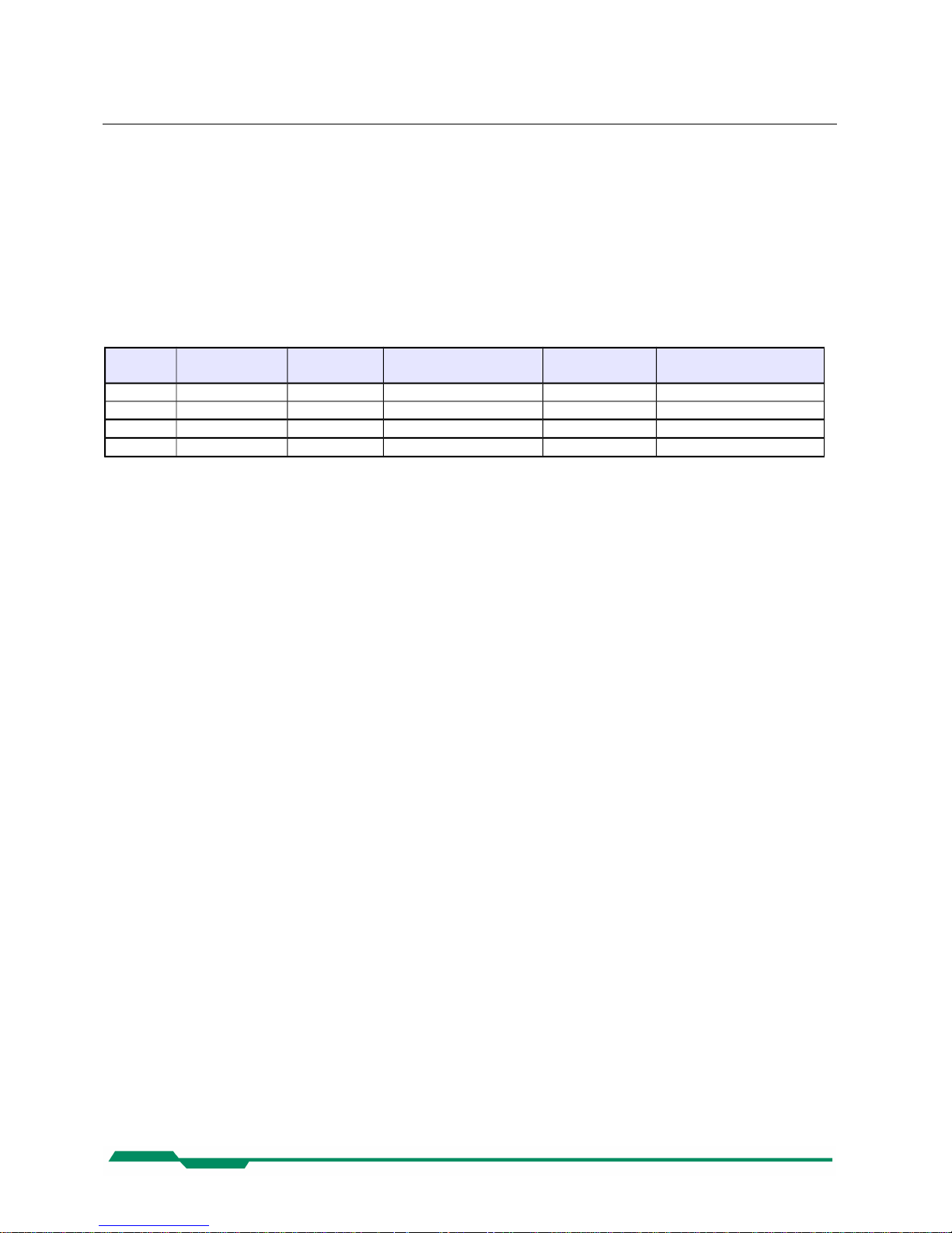
The camera models also differ in the maximal CoaXPress Link Speed they support..
The table below shows the different camera models and their max. frame rate:
Type Data width
(bits)
Color/
Mono
C/F-Mount lens
adaption
Link speed max. frame-rate @
2336 x 1728
MC4080 8/10 M C/F CXP-3 281 fps
MC4081 8/10 C C/F CXP-3 281 fps
MC4082 8/10 M C/F CXP-5 563 fps
MC4083 8/10 C C/F CXP-5 563 fps
2.3 Using the camera
There are no serviceable parts inside the camera. The camera may not be opened, otherwise
guarantee is lost.
Use dry, soft lens-cleaning tissue for cleaning lenses and, if necessary, the sensors window.
Don't use tools that may harm the sensor. Clean lenses and sensor from dust before rubbing
the lens/sensor surface.
8
Page 9

Hardware CoaXPress MC408x Camera Manual
3 Hardware
3.1 CoaXPress® interface
CoaXPress® is a new high speed interface standard for digital machine vision components including frame grabbers and cameras. CoaXPress® uses the GenICam standard for host/camera communication.
Benefits of the new technology are
• High transfer rates between camera and host up to 6.25 Gbps
• Good scalability
• By using the “electronically manual” of the GenICam® specification, CoaXPress
®
grants
compatibility and interchangeability between different CoaXPress hard- and software
components
• Connection between host and camera over (cheap) 75Ω Coax cables
• Max. Coax cable length can be influenced by selecting Link Speeds from 1.25 Gbps to
6.25 Gbps.
3.1.1 The GenICam standard
“The goal of GenICam is to provide a generic programming interface for all kinds of cameras.
No matter what interface technology the cameras are using or what features they are
implementing, the application programming interface (API) should be always the same
(GenICam Specification 1.0 ).”
Although CoaXPress do not support the full GenICam standard, it uses parts of the specification to ease the interchangeability between different CoaXPress® compliant components. Every camera must be provided with an 'electronically readable manual'. This manual can be
read and interpreted automatically by software components to control the features of a camera
in a generic way.
3.1.2 GenTL
GenTL is one part of the GenICam standard. It defines a hard- and software independent interface that each CoaXPress® compliant frame grabber must support. One of the benefits that
GenTL offers to the user is a general and well defined interface to communicate with the camera over the frame grabber hardware. So the user is not 'chained' to a software offered by the
frame grabber manufacturer. He can use the software of its choice select from all components
that supports the CoaXPress® and GenTL compliant interface.
9
Page 10

Hardware CoaXPress MC408x Camera Manual
3.2 Power supply
The camera needs a DC supply voltage between 12 … 24V at a power consumption of 7 Watt
max.
The power supply unit is connected to a dedicated connector at the back side of the camera.
Please take attention to the pin wiring of the connector as described below.
Before applying power to the camera we strongly recommend to verify the used
pins of the power connector, the polarity (+/-) of the leads and the supply voltage.
The camera may only be used with a supply voltage according to the camera
specification. Connecting a lower or higher supply voltage, AC voltage, reversal
polarity or using wrong pins of the power connector may damage the camera. If
doing so, the warranty will expire immediately.
10
Page 11

Getting started CoaXPress MC408x Camera Manual
4 Getting started
Before starting to operate the camera, make sure that the following equipment is available:
Camera MC408x
C-Mount/F-Mount lens
Mikrotron Support CD
Image processing system, e.g.: PC and software
Completely installed CoaXPress frame grabber (Device Driver, Software,...)
CoaXPress® cable according to the CoaXPress specification
Take care, that all components of the camera/host chain (camera,
grabber, software) are fully CoaXPress® compliant.
For a detailed cable description read the according section below.
4.1 First steps
Switch off the image processing system
Connect the camera to your CoaXPress® frame grabber with an appropriate
CoaXPress® cable.
Connect a power supply to the camera.
Unscrew dust protection cover from the camera and screw in a lens.
Switch on the image processing system and the external camera power supply
11
Page 12

Initial setup CoaXPress MC408x Camera Manual
5 Initial setup
The MC408x is delivered with initial parameters and therefore does not need to be configured
via the host software.
5.1 Serial number and firmware revision
Serial number and firmware revision is provided in MC408x non volatile memory. Use the according GenICam feature to read the serial number and firmware revision from the camera
(see feature list below). The serial number is also marked on the type plate of the camera.
5.2 PowerUpProfile
A Power Up Profile, permanently stored in the non-volatile memory of the camera, gets loaded
automatically if the camera is powered up. The profile consists of a number of camera settings
that configures the camera to a defined operation state. So no configuration from the host may
necessary to bring the camera to a good working condition. This includes values like the sen sor resolution or the frame rate, for example.
12
Page 13

Configuration CoaXPress MC408x Camera Manual
6 Configuration
6.1 Camera configuration
The MC408x is based on the CoaXPress® specification. CoaXPress® itself uses elements of
the GenICam standard to configure and control the camera. GenICam assumes that the cam era uses a flat register layout for configuration. For example if you want to change the expo sure time of the camera, you have to write the according value to the camera register representing the exposure time (e.g. 0x1100).
All camera registers are described and summarized in an 'electronically readable manual' file.
A register element in this manual is also called a feature. The file itself is coded in ASCII using
the Extensible Markup Language (XML) to describe each register as a XML feature knot.
Each knot consists, at least, of the type of the feature (command, string, integer,...), its access
mode(R/W), a descriptive name ('friendly name') of the feature, the corresponding register address and a short description of the feature in plain ASCII text. There are also a number of additional elements that make out a complete feature description. For example the min. and
max. values for a feature or its default value. Please refer to the GenICam documentation for
further details.
The features itself in the XML file are grouped according to their meaning (e.g. Bottstrap regis ters, Image format,...).
The XML file itself can be saved (compressed or uncompressed) in the camera or can be an
external file on the local computer or an remote host. The path (URL) to the file can be read
from the camera feature 'XmlUrlAddress' (see feature list below).
The features exposed by the camera and described in the XML file can be roughly subdivided
in four groups:
In a set of 9 mandatory features for a basic camera control as described in the
CoaXPress® specification.
In a set of mandatory boot registers, used by the host software to connect itself to the camera,
to do some connection related settings and to get the path to the XML file and read out the
camera feature list. This features are also a part of the CoaXPress specification. The boot reg isters are the only camera registers that have the same address for a specific register on ev ery CXP compliant camera, no matter who manufactured it.
Not mandatory camera features, which names and meanings are defined in the GenICam
'Standard Features Naming Convention' (SFNC).
Custom features, which names and meaning are special to a manufacturer/camera.
A camera must implement all mandatory features and all boot registers as described in the
CoaXPress® specification to be CoaXPress® compliant. Some of them are defined in the
GenICam and in the CoaXPress® standard, some of them are CoaXPress® specific.
13
Page 14

Configuration CoaXPress MC408x Camera Manual
All integer values are interpreted as 32 bit unsigned integers, if not other men tioned.
All Strings are NULL terminated and consists of 8 bit chars.
6.2 Bootstrap registers
CoaXPress® compliant Devices must support a number of bootstrap registers as defined in
this chapter. In contrast to other CXP camera features, each bootstrap register is assigned to
a fixed camera address which is defined in the CoaXPress® specification.
The Bootstrap registers are defined for device information and to allow the frame grabber to
establish and maintain the connection between the host and the camera. The connection to
the camera is handled by the frame grabber in the 'background' and is normally not in the
scope of an application developer. So namely the registers for establishing and maintaining
the grabber/camera connection may be not of interest for the 'normal' application programmer.
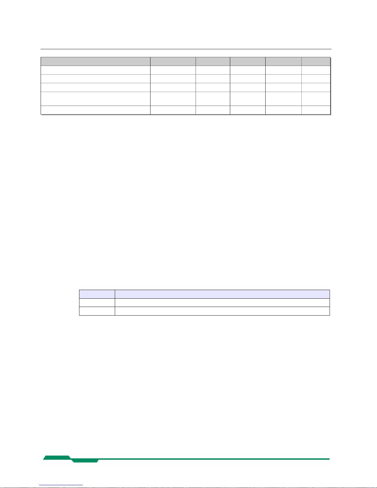
Name Address Access Length(bytes) Interface Chapter
Standard 0x00000000 R 4 IInteger 1.3.1
Revision 0x00000004 R 4 IInteger
XmlManifestSize 0x00000008 R 4 IInteger
XmlManifestSelector 0x0000000C R/W 4 IInteger
XmlVersion
[XmlManifestSelector]
0x00000010 R 4 IInteger
XmlSchemaVersion
[XmlManifestSelector]
0x00000014 R 4 IInteger
XmlUrlAddress
[XmlManifestSelector]
0x00000018 R 4 IInteger
IidcPointer 0x0000001C R 4 IInteger
DeviceVendorName 0x00002000 R 32 IString
DeviceModelName 0x00002020 R 32 IString
DeviceManufacturerInfo 0x00002040 R 48 IString
DeviceVersion 0x00002070 R 32 IString
DeviceFirmwareVersion 0x00002090 R 32 IString
DeviceID 0x000020B0 R 16 IString
DeviceUserID 0x000020C0 R/W 16 IString
LinkReset 0x00004000 W/(R) 4 IInteger
DeviceLinkID 0x00004004 R 4 IInteger
MasterHostLinkID 0x00004008 R/W 4 IInteger
ControlPacketDataSize 0x0000400C R 4 IInteger
StreamPacketDataSize 0x00004010 R/W 4 IInteger
LinkConfig 0x00004014 R/W 4 IEnumerate
14
Page 15
Configuration CoaXPress MC408x Camera Manual
Name Address Access Length(bytes) Interface Chapter
LinkConfigDefault 0x00004018 R 4 IInteger
TestMode 0x0000401C R/W 4 IInteger
TestErrorCountSelector 0x00004020 R/W 4 IInteger
TestErrorCount
[TestErrorCountSelector]
0x00004024 R/W 4 IInteger
Start of manufacturer specific register space 0x00006000 - - -
6.2.1 Standard
Description: This register provides a magic number indicating the Device implements the CoaXPress® stan-
dard.
Access Read
Type: Unsigned integer
In: -
Out: 0xC0A79AE5
Remark:
6.2.2 Revision
Description: This register provides the revision of the CoaXPress® specification implemented by this Device.
Access Read
Type: Unsigned integer
In: -
Out:
Bits Description
31-16 Major Revision
15-00 Minor Revision
Remark: For version 1.5 → 0x00010005
6.2.3 XmlManifestSize
Description: This register returns the number of available XML manifests. At least one manifest must be avail-
able.
Access Read
Type: Unsigned integer
In: -
Out: 1 ... N
Remark:
15
Page 16
Configuration CoaXPress MC408x Camera Manual
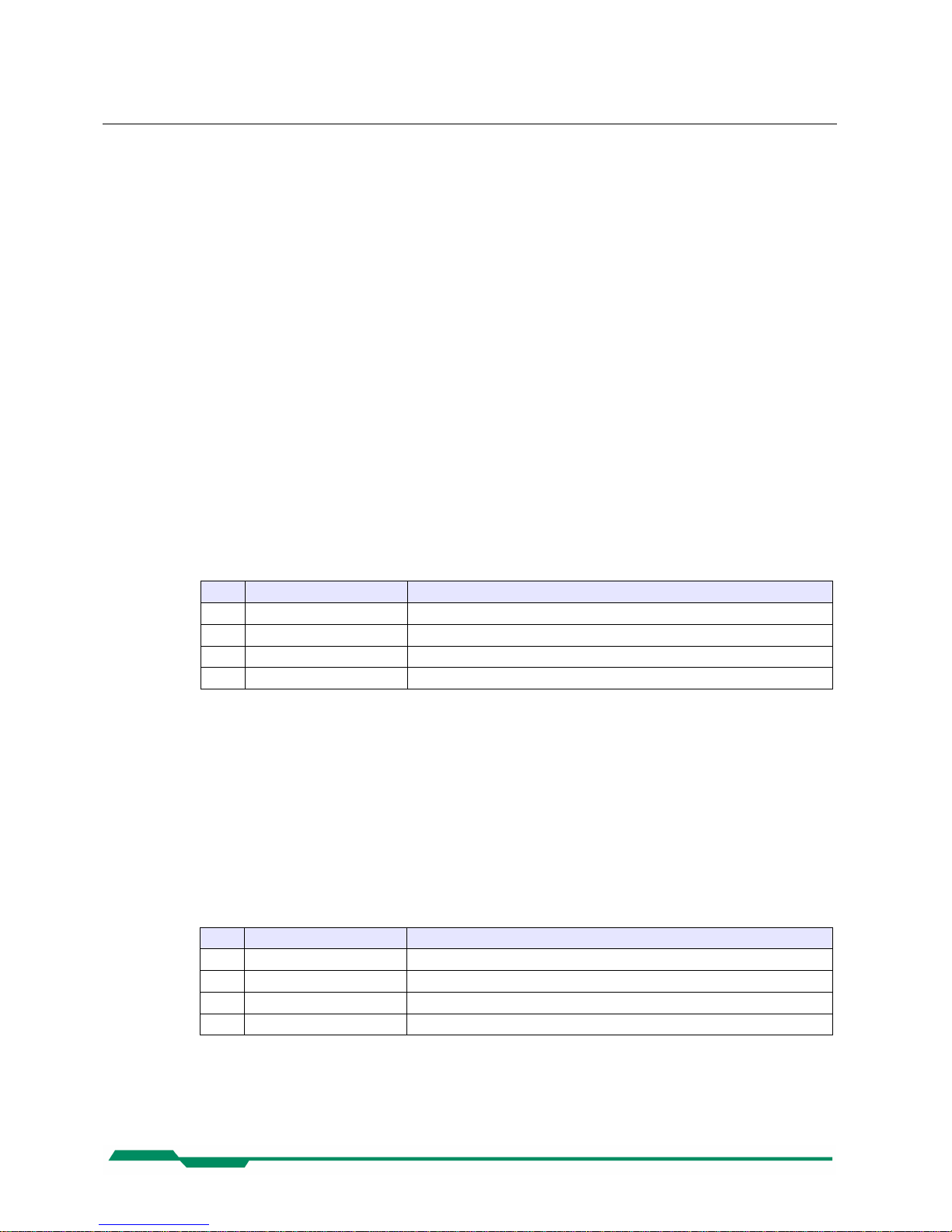
6.2.4 XmlManifestSelector
Description: This register selects the required XML manifest registers. It holds a number between 0 and
XmlManifestSize – 1.
Access Read / Write
Type: Unsigned integer
In: 0 … XmlManfiesSize-1
Out: 0 … XmlManfiesSize-1
Remark: A link reset sets the value to 0x00000000.
6.2.5 XmlVersion[ XmlManifestSelector ]
Description: This register provide the version number for the XML file given in the manifest referenced by
register XmlManifestSelector.
Access Read
Type: Unsigned Integer
In: -
Out:
Bits Name Description
31-24 Reserved Shall be 0
23-16 XMLMajorVersion The major version number of the XML file
15-8 XMLMinorVersion The minor version number of the XML file
7-0 XMLSubMinorVersion The sub-minor version number of the XML file
Remark:
6.2.6 XmlSchemaVersion[ XmlManifestSelector ]
Description: This register provides the GenICam schema version for the XML file given in the manifest refer -
enced by register XmlManifestSelector
Access Read
Type: Unsigned Integer
In: -
Out:
Bits Name Description
31-24 Reserved Shall be 0
23-16 SchemaMajorVersion The major version number of the schema used by the XML file
15-8 SchemaMinorVersion The minor version number of the schema used by the XML file
7-0 SchemaSubMinorVersion The sub-minor version number of the schema used by the XML file
Remark:
16
Page 17

Configuration CoaXPress MC408x Camera Manual
6.2.7 XmlUrlAddress[ XmlManifestSelector ]
Description: This register provides the address of the start of the URL string referenced by register
XmlManifestSelector.
Access Read
Type: Unsigned integer
In: -
Out: Register address
Remark: Reading from the returned register address returns N chars representing the name, the register
address and the length of the GenICam XML file stored in the flash memory of the camera.
The format of the address string is:
Field Description
Local Indicates the XML file is stored in non-volatile memory in the Device.
<Filename> The name of the XML file. The file name has no meaning if the XML file is stored in the camera.
<Extension> “xml” indicates an uncompressed text XML file.
“zip” indicates a ZIP format compressed text file.
<Address> The start address of the file in the Device memory map, given in hexadecimal form without
a leading “0x”. The address string can be read from this address.
<Length> The length of the file in bytes, given in hexadecimal without a leading “0x”.
Example: “Local:Mikrotron_MC4080_Rev1.xml;B8000;33A”
References an GenICam XML file in the flash memory of the camera.
The file can be read starting at address 0xB8000 and has a length of 0x33a Bytes.
The returned string could also reference a XML file located on the vendors Homepage. This location ist not used by our cameras.
6.2.8 IidcPointer
Description: The register provide the address of the start of the IIDC register space.
Access Read
Type: Unsigned integer
In: -
Out: 0x00000000.
Remark: Not supported
17
Page 18

Configuration CoaXPress MC408x Camera Manual
6.2.9 DeviceVendorName
Description: This register provides the name of the manufacturer of the Device as a NULL-terminated string.
Access Read
Type: String[0...32]
In: -
Out: Vendor name
Remark: Example: “Mikrotron GmbH”
6.2.10 DeviceModelName
Description: DeviceModelName
Access Read
Type: String[0...32]
In: -
Out: Model name
Remark: Example: “MC4082”
6.2.11 DeviceManufacturerInfo
Description: This register provide extended manufacturer-specific information about the Device as a NULL-
terminated string.
Access Read
Type: String[0...48]
In: -
Out: Manufacturer information
Remark: Example: “Mikrotron GmbH”
18
Page 19
Configuration CoaXPress MC408x Camera Manual
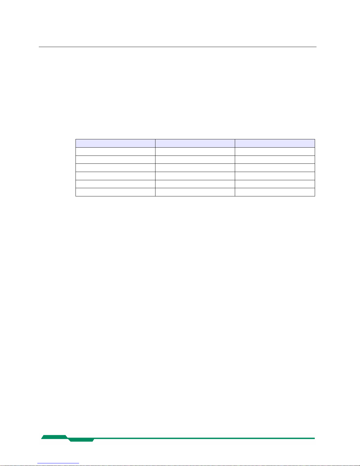
6.2.12 DeviceVersion
Description: This register provides the version of the camera hardware as a NULL-terminated string.
Access Read
Type: String[0...32]
In: -
Out: Device version string
Remark: Format of the version string (Byte numbers from left to right):
Byte Description Sample
0 Hardware tag “H”
1-3 Hardware version major number “000”
4 “.”
5-7 Hardware version minor number “001”
8 “.”
9-13 Hardware version sub minor number “00000”
So the sample row would result in the device version string:
“H000.100.00000”
19
Page 20
Configuration CoaXPress MC408x Camera Manual
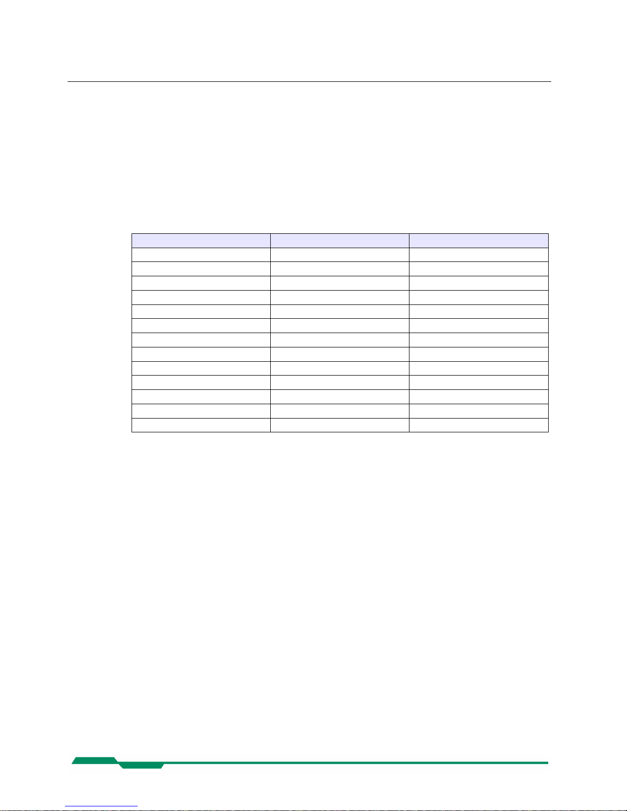
6.2.13 DeviceFirmwareVersion
Description: This register provides the version of the firmware in the Device as a NULL-terminated string.
Access Read
Type: String[0...32]
In: -
Out: Firmware version string
Remark: Format of the version string (Byte numbers from left to right):
Byte Description Sample
0 Controller software version tag “V”
1-3 Software version major number “000”
4 “.”
5-7 Software version minor number “013”
8 “.”
9-13 Software version sub minor number “00007”
14 Delimiter “-”
15 FPGA program version tag “F”
16-18 FPGA version major number “000”
19 “.”
20-22 FPGA version minor number “015”
23 “.”
24-28 FPGA version sub minor number “00304”
So the sample row would result in the device version string:
“V000.013.00007-F000.015.00304”
6.2.14 DeviceID
Description: This register provides the serial number of the camera as a NULL-terminated string.
Access Read
Type: String[0...16]
In: -
Out: Serial number of the camera
Remark: Example: “000000000000157”
20
Page 21

Configuration CoaXPress MC408x Camera Manual
6.2.15 DeviceUserID
Description: This register provides a user-programmable identifier for the camera as a NULL-terminated string.
Access Read / Write
Type: String[0...16]
In: User ID
Out: User ID
Remark: The User ID can free defined by the user.
It gets saved in the flash memory of the camera, so that it is preserved even if the camera power
is switched off.
6.2.16 LinkReset
Description: Initiates a Device link reset.
Access Read / Write
Type: Unsigned integer
In: 0x00000001
Out: 0x00000000
Remark: A Link Reset sets the bit rate of the camera to the discovery bit rate and resets all relevant values
to allow a new connection recovery by the host. A link reset stops a running image acquisition.
6.2.17 DeviceLinkID
Description: This register provide the ID of the Device link via which this register is read.
Access Read
Type: Unsigned Integer
In: -
Out: Link ID
Remark:
21
Page 22

Configuration CoaXPress MC408x Camera Manual
6.2.18 MasterHostLinkID
Description: This register holds the Host Link ID of the Host link connected to the Device Master link.
Access Read/Write
Type: Unsigned integer
In: Host Link ID
Out: Host Link ID
Remark: The value 0x00000000 is reserved to indicate an unknown Host ID.
All writes to Device extension links gets ignored.
6.2.19 ControlPacketDataSize
Description: This register provides the maximum control packet data size the Host can read from the Device,
or write to the Device, in multiples of 4 bytes
Access Read
Type: Unsigned integer
In: -
Out: Control packet size in multiples of 4 bytes.
Remark:
6.2.20 StreamPacketDataSize
Description: This register holds the maximum stream packet data size the Host can accept, in multiples of 4
bytes.
Access Read / Write
Type: Unsigned integer
In: Stream packet data size in multiples of 4 bytes.
Out: Stream packet data size in multiples of 4 bytes.
Remark: The Device can use any packet size it wants to up to this size.
A link reset sets the value 0x00000000.
22
Page 23
Configuration CoaXPress MC408x Camera Manual
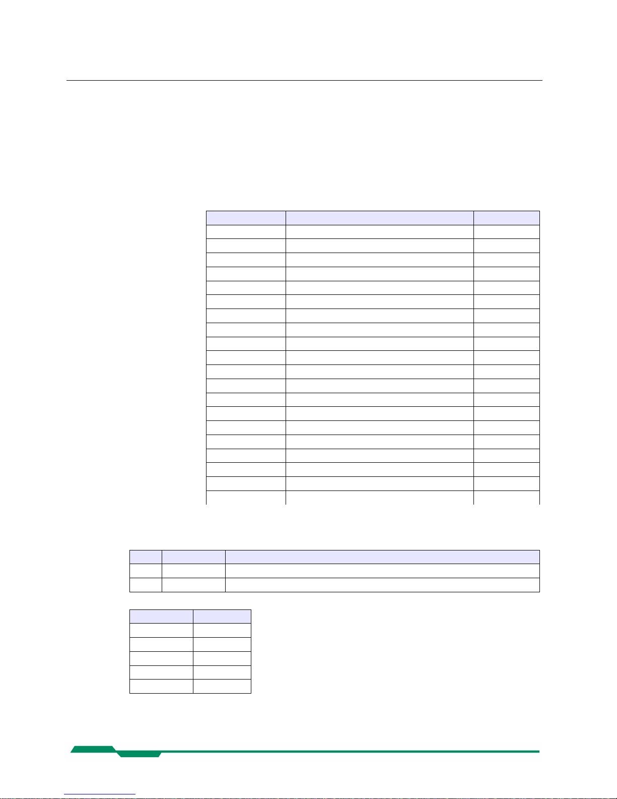
6.2.21 LinkConfig
Description: This register holds a valid combination of the Device link speed and number of active links. Writ-
ing to this register sets the link speeds on the specified links.
Access Read / Write
Type: Enumeration
In: Link configuration :
Enumeration Description Model
LINK1SPEED1250 One Link, 1.250 Gbps CXP-3 & CXP-6
LINK2SPEED1250 Two Links, 1.250 Gbps CXP-3 & CXP-6
LINK3SPEED1250 Three Links, 1.250 Gbps CXP-3 & CXP-6
LINK4SPEED1250 Four Links, 1.250 Gbps CXP-3 & CXP-6
LINK1SPEED2500 One Link, 2.500 Gbps CXP-3 & CXP-6
LINK2SPEED2500 Two Links, 2.500 Gbps CXP-3 & CXP-6
LINK3SPEED2500 Three Links, 2.500 Gbps CXP-3 & CXP-6
LINK4SPEED2500 Four Links, 2.500 Gbps CXP-3 & CXP-6
LINK1SPEED3125 One Link, 3.125 Gbps CXP-3 & CXP-6
LINK2SPEED3125 Two Links, 3.125 Gbps per Link CXP-3 & CXP-6
LINK3SPEED3125 Three Links, 3.125 Gbps per Link CXP-3 & CXP-6
LINK4SPEED3125 Four Links, 3.125 Gbps per Link CXP-3 & CXP-6
LINK1SPEED5000 One Link, 5.000 Gbps CXP-6
LINK2SPEED5000 Two Links, 5.000 Gbps per Link CXP-6
LINK3SPEED5000 Three Links, 5.000 Gbps per Link CXP-6
LINK4SPEED5000 Four Links, 5.000 Gbps per Link CXP-6
LINK1SPEED6250 One Link, 6.250 Gbps CXP-6
LINK2SPEED6250 Two Links with 6.250 Gbps per Link CXP-6
LINK3SPEED6250 Three Links, 6.250 Gbps per Link CXP-6
LINK4SPEED6250 Four Links, 6.250 Gbps per Linkm CXP-6
Out: Link configuration
Remark: Format of the enumeration values:
Bits Name Description
31-16 Number of links Number of Device links to use (e.g. 1 for one link, 2 for two links, etc.)
15-0 Link speed Bit rate selection code (see table below)
Bit Rate (Gbps) Bit Rate Code
1.250 0x28
2.500 0x30
3.125 0X38
5.000 0x40
6.250 0x48
Example: 4 Links by an connection speed of 3.125 Gbps → 0x00040038
23
Page 24

Configuration CoaXPress MC408x Camera Manual
6.2.22 LinkConfigDefault
Description: This register provides the value of the LinkConfig register that allows the Device to operate in its
default mode. This feature is not supported in the current version.
Access Read
Type: Unsigned integer
In: -
Out: 0x00000000
Remark: This allows a simple Host (e.g. a basic “closed system” format converter) to automatically set the
correct bit rate and obtain images from a Device
6.2.23 TestMode
Description: Writing the value 0x00000001 to this register enables test packets transmission from Device to
Host.
Access Read / Write
Type:
In:
Value Description
0x00000000 Normal operation mode
0x00000001 Sending test packets to host
Out: Same as above
Remark:
6.2.24 TestErrorCountSelector
Description: This register selects the required TestErrorCount[] register. It shall hold a valid Device Link ID.
Access Read / Write
Type: Unsigned integer
In: 0x00000000...0x00000003
Out: 0x00000000...0x00000003
Remark:
24
Page 25

Configuration CoaXPress MC408x Camera Manual
6.2.25 TestErrorCount[ TestErrorCountSelector ]
Description: This register provides the current link error count for the Device Link ID stored in register
TestErrorCountSelector.
Access Read / Write
Type: Unsigned Integer
In: 0x00000000
Out: Error count
Remark: Writing 0x00000000 to this register resets the error count for the Device Link ID stored in register
TestErrorCountSelector to zero.
A link reset sets all link error counters to zero.
25
Page 26

Configuration CoaXPress MC408x Camera Manual
6.3 Acquisition Control
Name Access Length(bytes) Interface Chapter
AcquisitionMode R/W 4 IEnumeration
AcquisitionStart W 4 ICommand
AcquisitionStop W 4 ICommand
ExposureMode R/W 4 IEnumeration
ExposureTime R/W 4 IInteger
ExposureTimeMax R 4 IInteger
AcquisitionFrameRate R/W 4 IInteger
AcquisitionFrameRateMax R 4 IInteger
TriggerMode R/W 4 iEnumeration
TriggerSource R/W 4 IEnumeration
SoftwareTrigger W 4 ICommand
6.3.1 AcquisitionMode
Description: This feature controls the acquisition mode of the Device.
Access Read / Write
Type: Enumeration
In:
Enumeration Description
Continuous In this mode, the camera records a sequence of images.
Out: See above
Remark: Frame acquisition can be stopped with command 'AcquisitionStop '.
6.3.2 AcquisitionStart
Description: This feature starts acquisition from the Device.
Access Write
Type: Command
In: 0x00000001
Out: -
Remark: The feature 'AcquisitionMode' defines how images gets captured.
6.3.3 AcquisitionStop
Description: This feature stops acquisition from the Device.
Access Write
Type: Command
In: x00000001
Out: -
Remark:
26
Page 27
Configuration CoaXPress MC408x Camera Manual
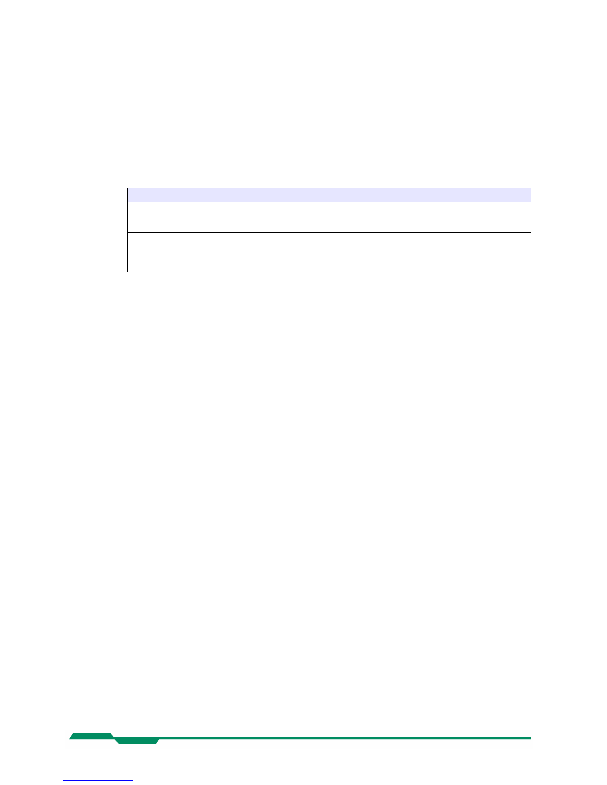
6.3.4 ExposureMode
Description: This feature sets the operation mode of the Exposure. It defines how a picture gets exposed if the
camera is in triggered mode.
Access Read / Write
Type: Enumeration
In:
Enumeration Description
Timed In this mode sets the camera to free running mode. The camera sends a continuous se-
quence of images to the frame grabber. The images gets exposed by the time defined by
the feature 'ExposureTime'. The frame rate is defined with feature 'AcquisitionFrameRate'.
TriggerWidth In this mode the camera waits for a trigger start message from the host to start to expose
the next image. The end of the exposure time is defined by an following trigger stop message. After receiving the exposure stop message the exposed image gets streamed to the
host. So the exposure time corresponds to the length of the trigger signal.
Out:
Remark: The ExposureMode is only relevant if the camera is in triggered mode. To set the camera to
triggered mode the feature TriggerMode must be set to 'On'.
6.3.5 ExposureTime
Description: This feature defines the exposure time in [µs] if the exposure mode is 'Timed'.
Access Read / Write
Type: Unsigned Integer
In: 0 … ExposureTimeMax
Out: Exposure time
Remark:
6.3.6 ExposureTimeMax
Description: This feature returns the maximal possible exposure time for the current camera settings in [µs].
Access Read
Type: Unsigned Integer
In: -
Out: Max. exposure time
Remark: The max. exposure time depends on the current frame rate.
27
Page 28
Configuration CoaXPress MC408x Camera Manual
6.3.7 AcquisitionFrameRate
Description: Controls the acquisition rate (in Hertz) at which the frames are captured.
Access Read / Write
Type: Unsigned Integer
In: 1 … AcquisitionFrameRateMax
Out: AcquisitionFrameRate
Remark: To capture continuously frames with the selected frame rate the camera must be in continuous
mode.
6.3.8 AcquisitionFrameRateMax
Description: This feature returns the max. possible frame rate in dependency of the current camera settings.
Access Read
Type: Unsigned Integer
In: -
Out: Max. frame rate
Remark: The max. frame rate depends on the currently defined frame size, on the used link speed and on
the number of CoaXPress lines used for image streaming.
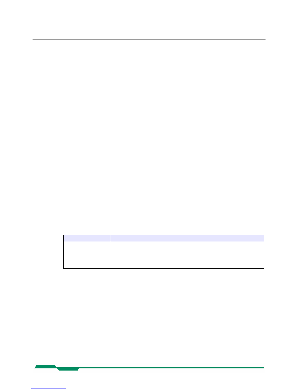
6.3.9 TriggerSelector
Description: This feature selects the trigger type to configure.
Access Read / Write
Type: Enumeration
In:
Enumeration Description
FrameStart If FrameStart is selected the camera will take one picture per trigger signal.
FrameBurstStart Selects a trigger that starts the camera to capture a sequence of frames on the occurrence
of a trigger signals. The number of frames captured is defined by the feature 'Acquisition-
BurstFrameCount'. controls the length of each burst unless a
FrameBurstEnd trigger is active.
Out: -
Remark: Set feature 'AcquisitionBurstFrameCount' to define the number of frames to capture if 'Frame-
BurstStart' is selected.
28
Page 29
Configuration CoaXPress MC408x Camera Manual
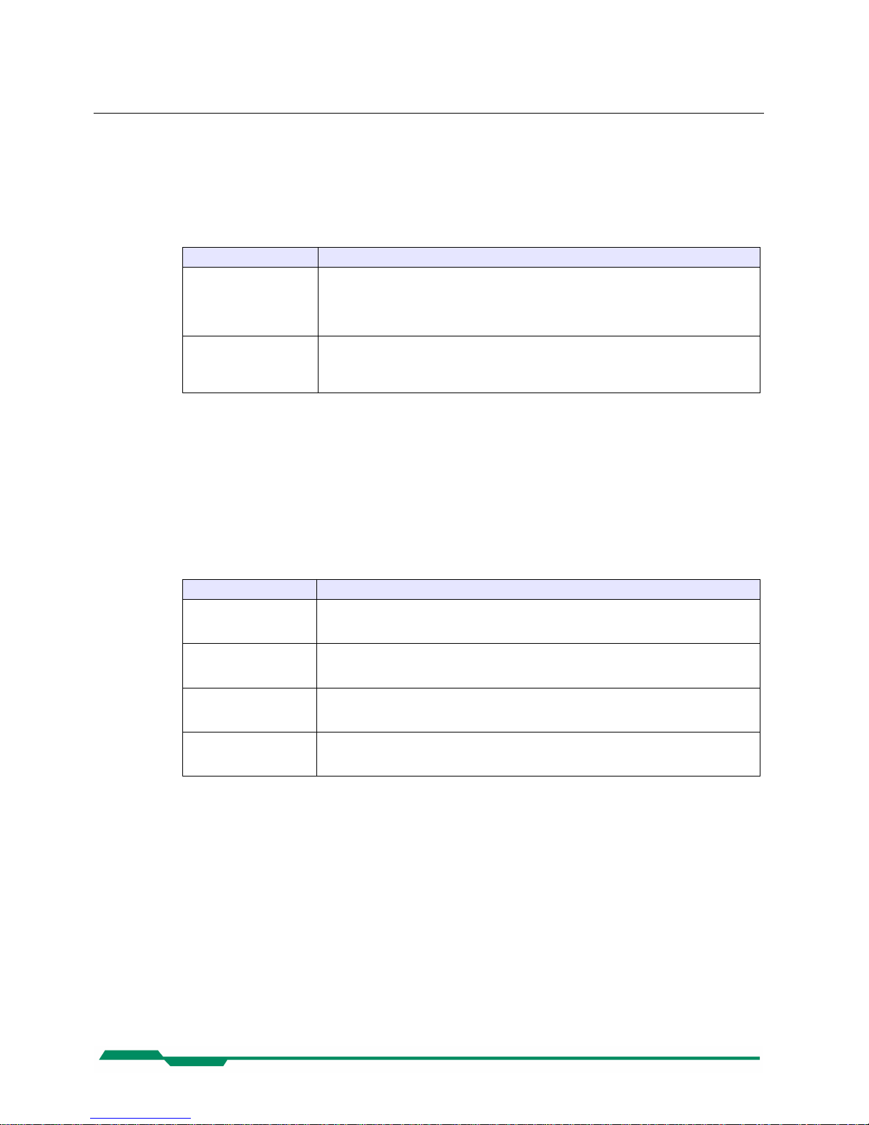
6.3.10 TriggerMode[ TriggerSelector ]
Description: This feature activates or deactivates the selected trigger type..
Access Read / Write
Type: Enumeration
In:
Enumeration Description
On This sets the camera to triggered mode. In triggered mode, the camera waits for a trigger
signal to take a picture. The trigger signal can be a (hardware) trigger signal from the frame
grabber or a software trigger initiated by a software command. If the trigger source is a
hardware or a software signal is defined by the feature 'TriggerSource'. The 'frame rate' of
the camera depends on the frequency of the trigger signals.
Off If the trigger mode is 'Off' the camera is set to free running mode. All trigger signals gets ig-
nored while the camera is in this mode. The camera captures continuously images that can
be send to the frame grabber. The frame rate is defined by the feature
'AcquisitionFrameRate', the exposure time by feature 'ExposureTime'.
Out:
Remark: The feature 'ExposureMode' defines how the camera exposes the next image as reaction to a
trigger signal. The settings of ExposureMode are only relevant if the camera is in triggered mode.
6.3.11 TriggerSource[ TriggerSelector ]
Description: This feature defines the source for the selected trigger type.
Access Read / Write
Type: Enumeration
In:
Enumeration Description
SoftwareTrigger If software is defined as the source of a trigger signal the user can trigger the camera to
take a picture by referencing the feature 'SoftwareTrigger'. It is no external (hardware) trigger signal needed to request a new image from the camera.
CXPTrigger If set to CXPTrigger, the camera waits for an external trigger signal from the frame grabber
before it makes a new image. How the image gets exposed depends on the setting of feature 'ExposureMode'.
Line0 If set to Line0 the camera waits for an external trigger signal on the CXP DIN 1.0/2.3 con-
nector to take an image. This feature is only available on Mikrotron CXP cameras with a
DIN 1.0 connector.
Line1 If set to Line1 the camera waits for an external trigger signal on the CXP DIN 1.0/2.3 con-
nector to take an image. This feature is only available on Mikrotron CXP cameras with a
DIN 1.0 connector.
Out: See above
Remark: There can always be just one trigger source active at one time.
29
Page 30

Configuration CoaXPress MC408x Camera Manual
6.3.12 TriggerActivation[ TriggerSelector ]
Description: This feature defines the activation mode for a selected trigger type.
Access Read / Write
Type: Enumeration
In:
Enumeration Description
RisingEdge The camera will start to capture frames on the arrival of a CXP 'trigger rising edge' trigger
packet. This activator expects a subsequent 'trigger falling edge' trigger packet to finish the
trigger sequence.
FallingEdge The camera will start to capture frames on the arrival of a CXP 'trigger falling edge' trigger
packet. This activator expects a subsequent 'trigger raising edge' trigger packet to finish the
trigger sequence.
AnyEdge To increase the trigger frequency by 2 the activator 'AnyEdge' initiate a frame on arrival of a
'trigger rising edge' trigger packet as well as on arrival of a 'trigger falling edge' trigger
packet. There is no subsequent trigger packet needed to finish the trigger sequence.
Out: -
Remark: Using the activator 'AnyEdge' doubles the max. trigger frequency.
6.3.13 AcquisitionBurstFrameCount
Description: Tthis feature defines the number of frames to capture if trigger 'FrameBurstStart' is selected.
Access Read / Write
Type: Unsigned Integer
In: 1… 4294967295
Out: -
Remark:
6.3.1 SoftwareTrigger
Description: This command triggers the camera to make a new picture.
Access Write
Type: Command
In: 0x00000001
Out: -
Remark: To generate a software trigger signal
• 'TriggerSource' must be set to 'SoftwareTrigger'
• The exposure time for the new image is the time defined by the feature 'ExposureTime'
30
Page 31

Configuration CoaXPress MC408x Camera Manual
6.3.2 TestImageSelector
Description: This feature selects the type of test image that is sent by the camera. It also activates/deactivates
a frame counter who gets superimposed into each captured image.
Access Read / Write
Type: Enumeration
In:
Enumeration Description
Off This options sets the camera to normal operation mode.
GreyHorizontalRamp If this option is set, the camera sends an image with a horizontal moving gray scale ramp.
The test image includes also a frame counter superimposed in its image (see below).
FrameCounter If this option is set a frame counter is superimposed into each captured frame or ROI.
The frame counter overlays 4 pixel in the upper left corner of each frame. The counter starts
with 0 on each activation and will start with 0 again if reaching its max. value. The counter
will also be reset to 0 on each acquisition start command.
In 10 bit modes the bits 1..0 in each pixel gets set to 0.
Counter layout:
Pixel Meaning
0 Frame counter LSB part (counter bits 7..0).
The values of pixel 0 and 1 are used to build a consecutive running16 Bit frame
counter in little-endian notation. If the 16 bit counter overruns it starts with 0
again.
1 Frame counter MSB part (counter bits 15..8)
2 Frame counter active marker.
If the frame counter is active this value is always 0xAA.
3 ROI number.
For cameras with the Multi-ROI feature the frame counter is inserted in each
ROI. This value reflects the number of the ROI the frame counter is superimposed starting from 1 for ROI 1. Because a 'set of ROI's' belongs always to one
frame the frame counter is in each ROI the same. For cameras without the MultiROI feature or if just one ROI is defined this value is always 1.
Out: Current test image selector.
Remark:
• A Link Reset sets the camera to normal operation mode.
• If the Grey Horizontal Ramp test pattern is selected the frame counter gets activated au-
tomatically too.
• Acquisition-Stop/Start sets the frame counter to 0.
• Activating the FrameCounter also reset the counter to 0.
31
Page 32
Configuration CoaXPress MC408x Camera Manual
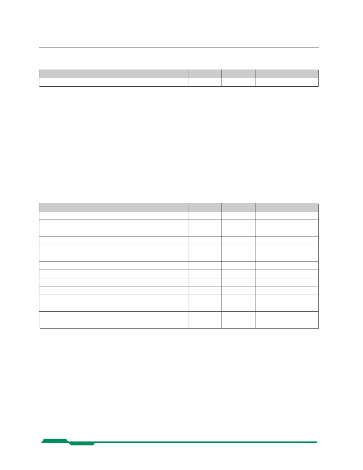
6.4 Device Control
Name Access Length(bytes) Interface Chapter
DeviceReset W 4 ICommand
6.4.1 DeviceReset
Description: Resets the device to its power up state.
Access Write
Type: Unsigned Integer
In: 0x00000001
Out: -
Remark:
6.5 Image Format
Name Access Length(bytes) Interface Chapter
Width R/W 4 IInteger
Height R/W 4 IInteger
OffsetX R/W 4 IInteger
OffsetY R/W 4 IInteger
DecimationHorizontal R/W 4 IInteger
DecimationVertical R/W 4 IInteger
SensorWidth R 4 IInteger
SensorHeight R 4 IInteger
WidthMax R 4 IInteger
HeightMax R 4 IInteger
PixelFormat R/W 4 IEnumeration
TapGeometry R/W 4 IEnumeration
Image1StreamID R 4 IInteger
Image2StreamID R IInteger
6.5.1 Width
Description: This feature provides the image width in pixels.
Access Read / Write
Type: Unsigned Integer
In: 16… WidthMax
Out: Image width
Remark:
• The image width must be incremented in 16 pixel increments.
• The maximal image width is calculated as SensorWidth – OffsetX.
32
Page 33

Configuration CoaXPress MC408x Camera Manual
6.5.2 Height
Description: This feature provides the image height in lines.
Access Read / Write
Type: Unsigned Integer
In: 2 … HeightMax
Out: Image height
Remark:
• The image height must be incremented in 2 lines increments.
• The maximal image height is calculated as SensorHeight – OffsetY.
6.5.3 OffsetX
Description: Horizontal offset from the origin to the area of interest (in pixels).
Access Read / Write
Type: Unsigned Integer
In: 0 … OffsetXMax
Out: Horizontal offset
Remark: The offset must be incremented in 16 pixel increments.
6.5.4 OffsetY
Description: Vertical offset from the origin to the area of interest (in lines).
Access Read / Write
Type: Unsigned Integer
In: 0 … OffsetYMax
Out: Vertical offset
Remark: The offset must be incremented in 2 lines increments.
33
Page 34

Configuration CoaXPress MC408x Camera Manual
6.5.5 DecimationHorizontal
Description: Horizontal sub-sampling of the image.
Access Read / Write
Type: Unsigned Integer
In: 1 … 2
Out: Current horizontal decimation factor
Remark: This value defines that each Nth image pixels in horizontal direction must be sampled to build the
image. So the size of the image gets reduced in horizontal direction by the factor of Decimation-
Horizontal. A decimation factor of 1 means no horizontal decimation. The Width value must be set
to the requested number of horizontal pixels. Width * DecimationHorizontal may not exceeds the
horizontal sensor size or an error gets returned.
Example: To get a sub sampled image which covers the whole horizontal sensor width but uses
just the half number of horizontal pixels you have to set the Width parameter to SensorWidth / 2
and the DecimatinHorizontal factor to 2. This will result in an image which is clinched in the horizontal direction by factor 2 but covering the whole horizontal senor width.
6.5.6 DecimationVertical
Description: Vertical sub-sampling of the image.
Access Read / Write
Type: Unsigned Integer
In: 1 … 255
Out: Current vertical decimation factor
Remark: This value defines that each Nth image line in vertical direction must be sampled to build the im-
age. So the size of the image gets reduced in vertical direction by the factor of DecimationVertical.
A decimation factor of 1 means no horizontal decimation. The Height value must be set to the requested number of lines. Height * DecimationVertical may not exceeds the max. vertical sensor
size or an error gets returned.
Example: To get a sub sampled image which covers the whole vertical sensor height but uses
just the half number of lines you have to set the Height parameter to SensorHeight / 2 and the
DecimatinVertical factor to 2. This will result in an image which is clinched in the vertical direction
by factor 2 but covering the whole senor in vertical direction.
34
Page 35

Configuration CoaXPress MC408x Camera Manual
6.5.7 SensorWidth
Description: Effective width of the sensor in pixels.
Access Read
Type: Unsigned Integer
In: -
Out: Sensor width
Remark:
6.5.8 SensorHeight
Description: Effective height of the sensor in lines.
Access Read
Type: Unsigned Integer
In: -
Out: Sensor width
Remark:
6.5.9 WidthMax
Description: Maximum width (in pixels) of the image.
Access Read / Write
Type: Unsigned Integer
In: -
Out: Max. image width
Remark: The max. possible image width is calculated in dependency of the currently defined horizontal off -
set (OffsetX).
6.5.10 HeightMax
Description: Maximum height (in lines) of the image.
Access Read / Write
Type: Unsigned Integer
In: -
Out: Max. image height
Remark: The max. possible image height is calculated in dependency of the currently defined vertical off-
set (OffsetY).
35
Page 36
Configuration CoaXPress MC408x Camera Manual
6.5.11 PixelFormat
Description: This feature returns the format the camera uses for one pixel.
Access Read/Write
Type: Enumeration
In:
Enumeration Description Available for Camera type
Mono8 Monochrome, 8 bit/pixel monochrome, color
Mono10 Monochrome, 10 bit/pixel Monochrome, color
BayerGR8 /
BayerGR10
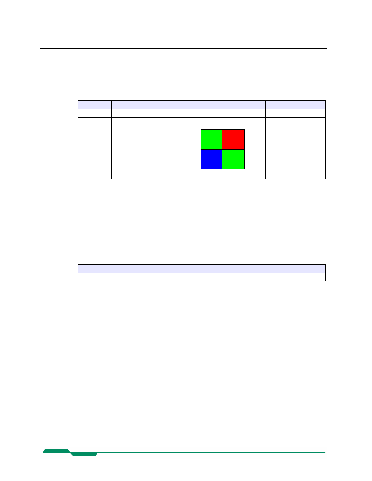
Bayer Pattern color image
Order of the Bayern Pattern:
color
Out: See above
Remark: The available pixel formats depends on the type of the camera (monochrome or color)
6.5.12 TapGeometry
Description: This feature describes the geometrical properties characterizing the taps of the camera as seen
from the frame grabber.
Access Read
Type: Enumeration
In:
Enumeration Description
Geometry_1X_1Y Single pixel scanning from left to right and single line scanning from top to button.
Out: See above
Remark:
6.5.13 Image1StreamID
Description: This gives the Stream ID of the primary image stream from the Device.
Access Read
Type: Unsigned Integer
In: -
Out: 0x00000001
Remark:
36
Green Red
Blue Green
Page 37
Configuration CoaXPress MC408x Camera Manual
6.5.14 Image2StreamID
Description: This gives the Stream ID of the secondary image stream from the Device.
Access Read
Type: Unsigned Integer
In: -
Out: 0x00000000
Remark: Not used
6.6 User Set Control
Name Access Length(bytes) Interface Chapter
UserSetSelector R/W 4 IEnumeration
UserSetLoad[UserSetSelector] W 4 ICommand
UserSetSave[UserSetSelector] W 4 ICommand
UserSetDefaultSelector R/W 4 IEnumeration
6.6.1 UserSetSelector
Description: Selects the feature User Set to load, save or configure.
Access Read / Write
Type: Enumeration
In:
Enumeration Description
Default Selects the factory setting User set.
UserSet1 Selects the first user set.
UserSet2 Selects the second user set.
UserSet3 Selects the third user set.
Out: See above
Remark: Set the UserSetSelector first to select a user set for further operations (see below).
37
Page 38

Configuration CoaXPress MC408x Camera Manual
6.6.2 UserSetLoad[UserSetSelector]
Description: Loads the User Set specified by UserSetSelector to the device and makes it active.
Access Write
Type: Command
In:
Out:
Remark: Loads the User Set selected by selector UserSetSelector from the camera flash memory to the
camera registers as the current configuration. If the selected User Set is not defined by previously
saving a camera configuration to this set, an error message gets returned.
The Default User Set is a set of factory settings that are predefined by the manufacturer.
6.6.3 UserSetSave[UserSetSelector]
Description: Save the User Set specified by UserSetSelector to the non-volatile memory of the device.
Access Write
Type: Command
In:
Out:
Remark: A previously saved user set gets overwritten by the new settings.
The Default User Set is a set of factory settings and can not be overwritten.
6.6.4 UserSetDefaultSelector
Description: Selects the feature User Set to load and make active when the device is reset.
Access Read/Write
Type: Enumeration
In:
Enumeration Description
Default Selects the factory setting User set.
UserSet1 Selects the first user set.
UserSet2 Selects the second user set.
UserSet3 Selects the third user set.
Out: Currently selected default User Set selector.
Remark:
38
Page 39
Configuration CoaXPress MC408x Camera Manual
6.7 Analog Controller
Name Access Length(bytes) Interface Chapter
Gain R/W 4 IInteger
BlackLevel R/W 4 IInteger
6.7.1 Gain
Description: The Gain defines an amplification of the video signal in %.
Access Read / Write
Type: Integer
In: 50...1000
Out: Current Gain.
Remark: A gain of 100% corresponds to an amplification of 1.
Gain is set to 100 by default.
6.7.2 BlackLevel
Description: BlackLevel defines a DC offset added to the video signal.
Access Read / Write
Type: Integer
In: 0...500
Out: Current BlackLevel.
Remark: BlackLevel is defined in % from a camera internal reference value.
Blacklevel is set to 100 by default.
6.8 Custom features
Name Access Length(bytes) Interface Chapter
DeviceInformationSelector R/W 4 IEnumeration
DeviceInformation[DeviceInfoSelector] R 4 IInteger
PrstEnable R/W 4 IEnumeration
PulseDrainEnable R/W 4 IEnumeration
39
Page 40
Configuration CoaXPress MC408x Camera Manual
6.8.1 DeviceInformationSelector
Description: This feature selects one of the elements from the device information list
Access Read / Write
Type: Enumeration
In:
Enumeration Description
InfoSnr Serial number of the camera (same as feature DeviceID)
InfoType Camera type / model
InfoSubType Camera sub type
InfoHwRevision Camera hardware revision
InfoFpgaVersion Camera FPGA program version
InfoSwVersion Microcontroller software version
InfoPwrSource Returns the source of the camera power supply (external Power Supply or PoCXP)
InfoPwrConsumption The actual power consumption of the camera in [µA]
InfoPwrCxpVoltage The actual voltage of the camera power supply in [mV]
Out: See above
Remark: First you have to set the selector to define the data you want to read. After setting the selector
you can read the data by reading register DeviceInformation (see below).
40
Page 41
Configuration CoaXPress MC408x Camera Manual
6.8.2 DeviceInformation[DeviceInfoSelector]
Description: This feature returns a value of the device information list selected by feature DeviceInfoSelector.
Access Read / Write
Type: Unsigned Integer
In: -
Out: Device information values
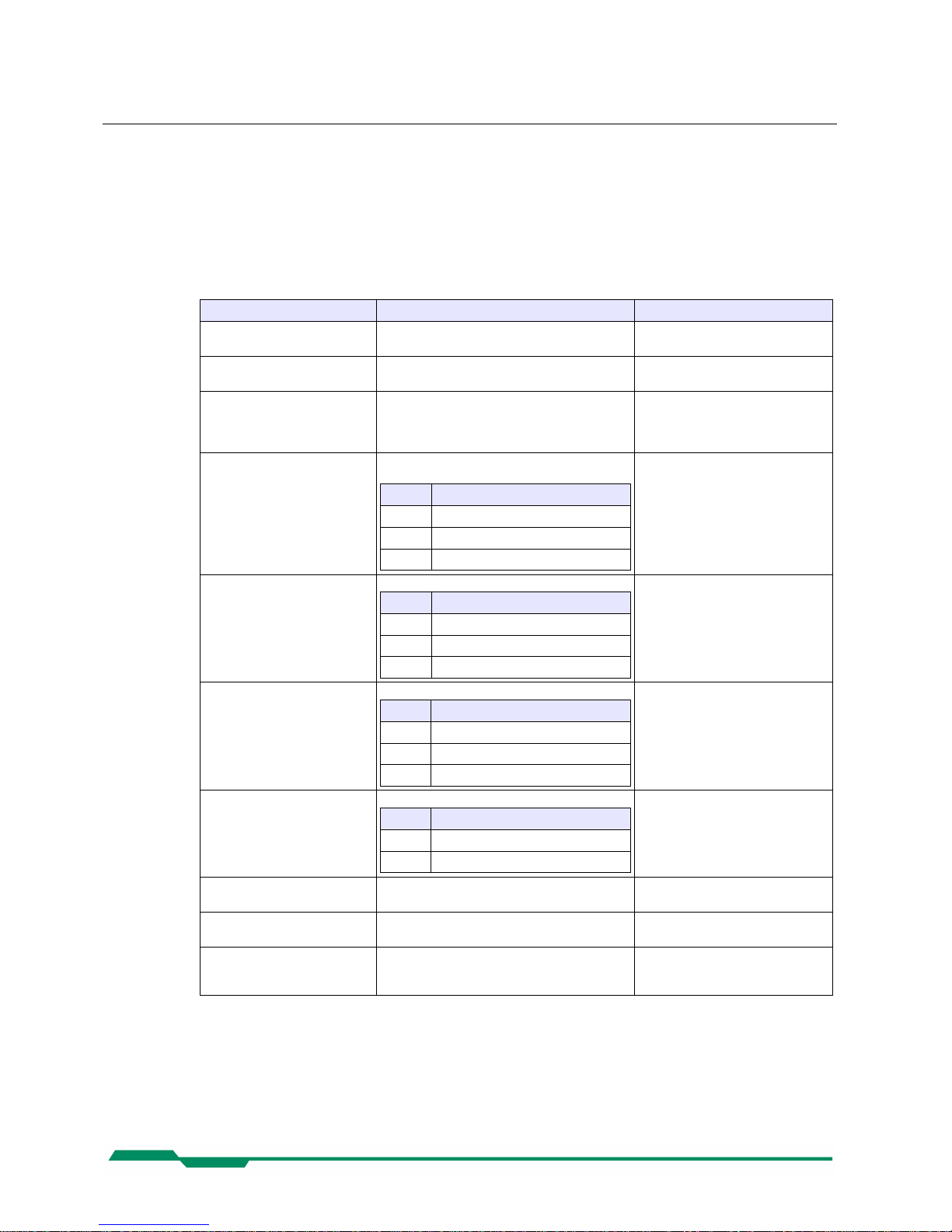
Selector Description Sample
InfoSnr Serial number of the camera (same as feature
DeviceID)
0x00000132
InfoType Camera type / model 0x00004080 →
Camera model MC4080
InfoSubType Sub type number of the camera model.
The subtype number describes models withs
special features and custom version of the camera.
0x00000001
InfoHwRevision This number describes the revision of the cam-
era hardware
Bits Description
31-24 Major revision number
23-16 Minor revision number
15-00 Build number
0x0103000B →
Revision 1.3 Build 11
InfoFpgaVersion Version of the FPGA program of the camera:
Bits Description
31-24 Major version number
23-16 Minor version number
15-00 Build number
0x02050001 →
Version 2.5 Build 1
InfoSwVersion Version of the Microcontroller software version:
Bits Description
31-24 Major version number
23-16 Minor version number
15-00 15-00
0x020F0011 →
Version 2.15 Build 17
InfoPwrSource Returns the source of the camera power supply.
Value Description
0 External Power Supply
1 Power Over CXP Line (PoCXP)
InfoPwrConsumption Returns the actual power consumption of the
camera in [µA]
0x00066580 → 419200 µA =
0.4192 A
InfoPwrCxpVoltage Returns the actual voltage of the camera power
supply in [mV]
0x2E4A → 11850 mV =
11.85 Volt
InfoTemperature Returns the current camera temperature in 0.5
degrees Celsius. The value returned is a signed
integer.
0x00000040 → 32 degree Celsius
0xFFFFFF2C → -2 degree Celsius
Remark:
• Model number, hardware revision, FPGA version and firmware version are also included
in the string of the 'DeviceVersion' Bootstrap feature.
41
Page 42
Configuration CoaXPress MC408x Camera Manual
6.8.3 CustomSensorClkEnable
Description: This feature enables/disables the camera clock overwriting by a customer selected value.
Access Read / Write
Type: Boolean
In:
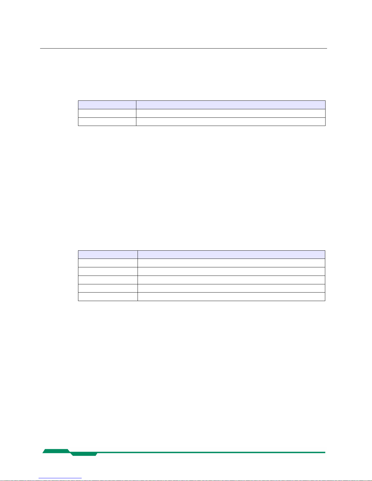
Value Description
On The camera uses the sensor clock defined with feature 'CustomSensorClk'.
Off The camera uses the default sensor clock defined for the current CoaXPress link settings.
Out:
On/Off
Remark: The 4CXP camera defines a default sensor clock for each CoaXPress link speed to run the cam-
era in an optimal frame rate / image quality relation.
With the custom sensor clock feature this default value can be overwritten by a customer selected
value (see feature 'CustomSensorClk' below). Overwriting the default sensor clock by a higher
sensor clock may result in substantial higher frame rates (depending on the frame size) but may
also downgrade the image quality. It is up to the user to find a setting that fits his needs.
This feature may be mainly of use for frame grabber boards with a max. link speed less than
CXP6.
6.8.4 CustomSensorClk
Description: Overwrites the default camera sensor clock by a customer defined value.
Access Read/Write
Type: Enumeration
In:
Enumeration Description
Clk_50MHz Set camera sensor clock to 50 MHz..
Clk_75MHz Set camera sensor clock to 75 MHz. (default for CXP1-CXP3)
Clk_100MHz Set camera sensor clock to 100 MHz.
Clk_125MHz Set camera sensor clock to 125 MHz. (default for CXP5)
Clk_150MHz Set camera sensor clock to 150 MHz. (default for CXP6)
Out: Currently selected sensor clock.
Remark: See above.
42
Page 43

Firmware update CoaXPress MC408x Camera Manual
7 Firmware update
Our 4CXP camera hardware is based on a number of programmable logical units. This allows
us to modify and update the firmware of the camera on an easy and fast way. The flexibility of
this concept guaranties you always to have an 'up to date' product. Further it allows us to inte grate new and improved function into our cameras, so you can profit on it. Even customer
modifications are possible to provide you with a camera that fits exactly your needs.
Normally it is not necessary to send your camera to us to do a firmware update. To simplify
the update procedure we will support you with an easy to handle 'Firmware Updater' program.
So it should be no problem for you to do an update by your own.
Please Note: Not all CXP frame grabber manufacturer supports our 'Firmware Updater' software. So if you should have any problems to update the camera firmware please contact us.
We are sure we will find a solution to accomplish the firmware update with your frame grabber
too.
43
Page 44

Technical Data CoaXPress MC408x Camera Manual
8 Technical Data
MC 4080 Monochrome
MC 4081 Color (Bayer Filter)
Resolution 2336 x 1728
Sensor type CMOS sensor
Pixel depth 8 Bit / 10 Bit monochrome or RGB (Bayer Filter)
Pixel size 7 x 7 µm
Active area 16.35 (H) x 12.10 (V) mm / 20.34 mm (diagonal)
Light sensitivity
Monochrome: 1.600 ASA , 9 V/lux-s
RGB-color:
1.200 ASA
Shutter Shutter time from 1 µs to 1 s in 2 µs steps
Internal dynamics Up to 80 dB using Dynamic Range Adjustment
Spectral bandwidth 350-850 nm
Fill factor x quantum efficiency 40%
Amplification Digital Gain 1-4 times (8 Bit modes), 1/4 steps
Video output CoaXPress®, CXP-5 and CXP-3,
5W5 up to 2.4 Gbyte/s
Communication CoaXPress® with Gen<I>Cam based technology
Trigger Asynchronous shutter over CoaXPress® interface
Power supply 12…24 V external power supply
Power consumption 7 W max.
Shock & vibration 70g, 7grms
Dimensions (WxHxD) 80 x 80 x 53 mm (C-Mount)
80 x 80 x 81 mm (F-Mount)
Case temperature +5…+50 °C
Weight 450 g (C-Mount)
490 g (F-Mount)
Lens mount C-/F-mount (depending on adapter)
44
Page 45
Technical Data CoaXPress MC408x Camera Manual
1 Resolution and Speed
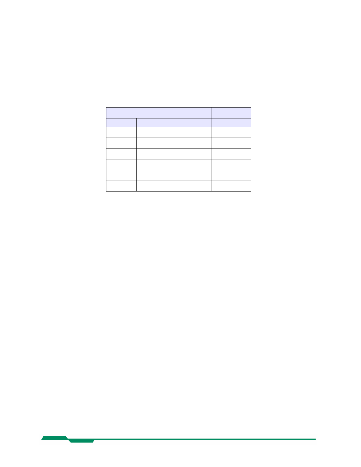
The table below shows a number of possible camera resolution and their max. speed for this
resolution for an 8 bpp image and 4 CXP Coax Lines. Please note, that the max. speed that finally can be achieved depends on the selected transfer rate (CXP-6/CXP-3) and the number
of CXP links used.
Resolution Speed (fps) Remark
H V CXP- 3 CXP- 6
2.336 1.728 281 563
2.048 1.024 474 949
1.920 1.080 450 900 Full HD!
1.280 1.024 474 949
1.280 720 674 1.349 Half HD!
2.336 512 974 1.894
45
Page 46
Technical Data CoaXPress MC408x Camera Manual
8.1 Spectral response
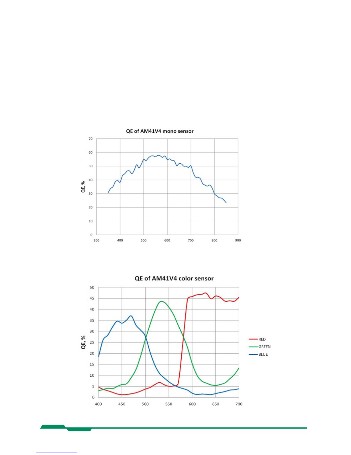
The charts below show the sensitivity of the monochrome and the color sensor with a bayer
pattern filter on the sensor glass lid. The color camera is by default equipped with a UV/IR cut
filter with a transmittance of 370-670nm resulting in a sensitivity shown in the second chart.
By request all types of cameras can be delivered with or without UV/IR cut filter.
1.1 Spectral response for the MC4080 (monochrome)
1.2 Spectral response for the MC4081 (color with Bayer Pattern filter)
46
Page 47
Technical Data CoaXPress MC408x Camera Manual
8.2 Bayer pattern filter
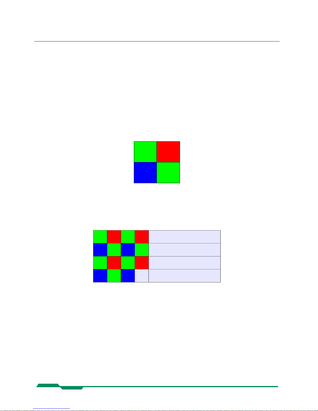
The EoSens color cameras have a Bayer Pattern filter on their sensor glass lid. To get the
color information the imaging software must decode the information for one pixel to RGB by
using the values of its neighbor pixels. There exists a lot of different Bayer Pattern algorithms,
which differ in speed and quality of the decoded image. You will find a lot of information and
algorithms on the Internet which handle the Bayer Pattern thematic.
The Bayern Patter filter of the MC408x consists of a number small red, green and blue filter elements, each covering exactly one pixel on the sensor. A matrix of 2 x 2 filter elements build a
filter element matrix. The order and the color of the filter elements building a 2 x 2 filter matrix
are always the same. The image below shows the colors and the order of a filter matrix as
used by our cameras.
Green
Red
Blue Green
The sensor is completely covered by identically 2 x 2 filter matrix elements. So, the color pattern of the first line of the matrix is repeated each mod(2) pixel number on each even line number. The color pattern of the second line is repeated on each (mod2) pixel on each odd line
number. That means, that always 2 consecutive lines shows exactly the same order of Bayer
Pattern elements.
Green Red Green Red •••
Blue Green Blue Green •••
Green Red Green Red •••
Blue Green Blue ••• •••
From the size and the order of a filter matrix element results...
• Any (sub) region of a Bayer Pattern coded image must always start with the same color
on the top left (0/0) pixel position of the region.
• A Bayer Pattern image must always have an even number of pixels and ann even number of lines.
• Changing the image size can only be done by steps of 2 in the horizontal and in the
vertically direction.
47
Page 48
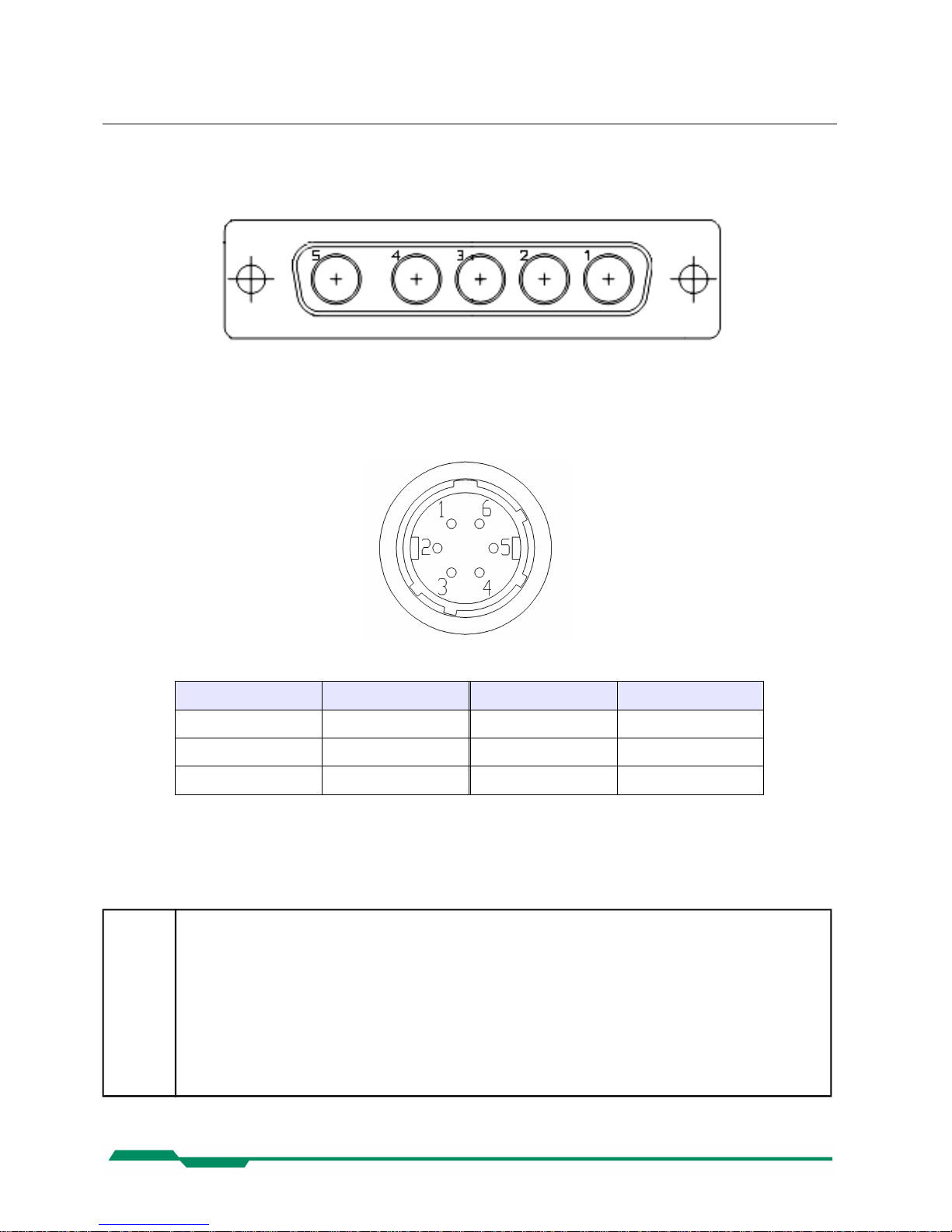
Technical Data CoaXPress MC408x Camera Manual
8.3 Connectors
8.3.1 CoaXPress® connector 5W5
All signals according to CoaXPress® specification
8.3.2 Circular power connector, 6-pin
Pin Signal Pin Signal
1 VCC 4 DGND*
2 VCC 5 GND
3 STRB 6 GND
*DGND ... digital GND for signal STROBE_OUT
Manufacturer: Hirose
Order no.: HR10A-7P-6S
Before applying power to the camera we strongly recommend to verify the used
pins of the power connector, the polarity (+/-) of the leads and the supply voltage.
The camera may only be used with a supply voltage according to the camera
specification. Connecting a lower or higher supply voltage, AC voltage, reversal
polarity or using wrong pins of the power connector may damage the camera. If
doing so, the warranty will expire immediately.
48
Page 49

Technical Data CoaXPress MC408x Camera Manual
8.4 Mechanical dimensions
49
4CX camera body
F - Mount C - Mount
 Loading...