

Page 1

1601 J. P. Hennessy Drive, LaVergne, TN USA 37086 615/641-7533 800/688-6359 www.ammcoats.com Manual Part No.: 8184554 01
HENNESSY INDUSTRIES INC. Manufacturer of AMMCO
®
, COATS®and BADA®Automotive Service Equipment and Tools. Revision Date: 01/05
Nitrogen Inflation System
Kit 8184553
For use with COATS Model Series Tire
Changers for Adding Nitrogen to the
Tire Changer as the Inflation Gas
®
Installation Instructions
with Parts Identification
READ these instructions before placing unit in
service KEEP these and other materials delivered
with the unit in a binder near the machine for
ease of reference by supervisors and operators.
Disclaimer
This is a supplemental instruction for handling nitrogen inflation systems and does not cover the safe operation of the machine, tire/rim
match, or evaluation of safe wheels and tires, or instructions covering
the safe inflation processes. If you need copies of operating instructions
call 1-800-688-6359 or refer to the internet at www.ammcoats.com.
: Do not exceed the design pressure of the equipment
when attaching a separate nitrogen gas inflation supply to the tire
changer. If the nitrogen gas pressure exceeds the design pressure of the
machine, the pressure relief valve will activate continuous; if the pressure
relief is increased, the machine is operating above the design pressure
and could create a hazardous condition.
For reference:
COATS tire changer models 90XX have a system designed for 145 PSI max-
imum input pressure.
COATS tire changer models 30XX, 40XX, 50XX, 60XX, and 70XX have a sys-
tem designed for 175 PSI maximum input pressure.
To comply with this requirement, a small (1/4-inch) adjustable pressure regulator may be required in series with the nitrogen input system; one is available from COATS as p/n 8183424, or Grainger p/n 4ZM14 (0-150 PSI
adjustable). Use the gauge on the tank to set the pressure.
CAUTION
Page 2
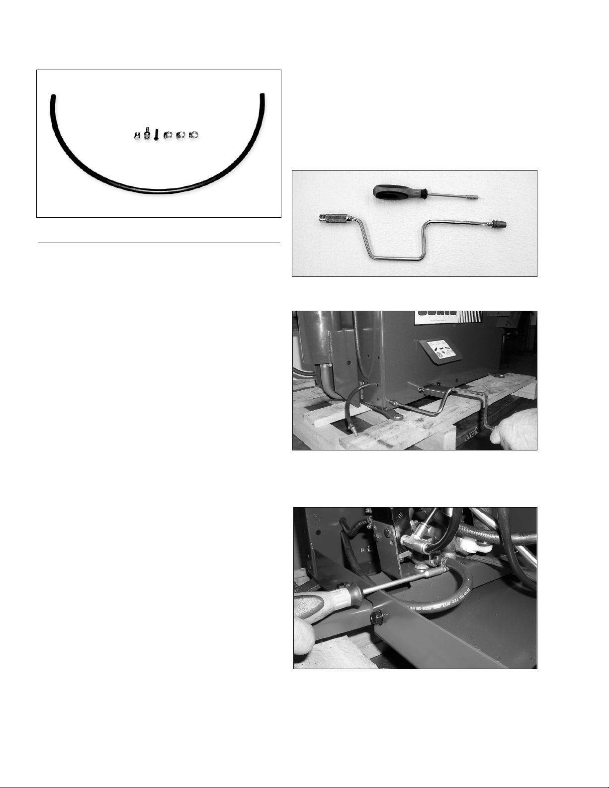
Parts Identification for the Nitrogen
Conversion Kit 8184553
Item Part No. Qty. Description
1 8120408 1 1/4-inch Bolt
2 8182090 1 1/4-inch ID Rubber Hose by 60-
inch long
3 8101428 3 Hose Clamp
4 8120344 1 1/4-inch NPT Plug
5 8000378 2 1/4-inch Barbed Fitting
Other Parts Required Per Location: The installer is
responsible for furnishing the correct matching quick
connector to the nitrogen source. This will normally be
the male end with either male or female 1/4-inch NPT.
Converting Standard COATS®50xx, 60xx,
or, 70xx Tire Changer To Nitrogen Tire
Inflation
Before beginning this modification or attempting any
maintenance, remove the electrical power and air
source from the machine; also, bleed off any stored
compressed air by exhausting through the air blast foot
valve.
Tools Required: Speed Handle with 3/8-inch Socket,
Spinner Handle 1/4-inch
1. With the speed handle and 3/8-inch socket,
remove the machine’s side panel.
2. Using the 1/4-inch spinner handle, loosen the hose
clamp and remove the rubber hose that is attached to
the upstream side of the 1/4-inch valve. This is the hose
between the 1/4 and 3/4-inch valve.
2
Page 3
3. With the hose that was just removed, from the kit
insert a 1/4-inch bolt into the hose end and using the
1/4-inch spinner handle, tighten the hose clamp. This
will prevent air pressure from escaping at the 3/4-inch
valve.
4. Next, using the length of hose from the kit, route
the hose through one of the holes in the back of the
chassis. Position the hose over the fitting on the 1/4inch valve and tighten the hose clamp from kit. At opposite end of the hose, install quick coupling fitting as
required for connection to nitrogen.
5. This is a diagram of the changes with the valve system removed from the chassis for clarity.
6. Replace the side pane.
7. Reconnect the air pressure supply to the machine
and the nitrogen supply to the machine and inspect for
leaks. If no leaks exist, test the machine for full function
before returning the machine to operation.
3
Plug In Hose
New Hose
for Nitrogen
Page 4

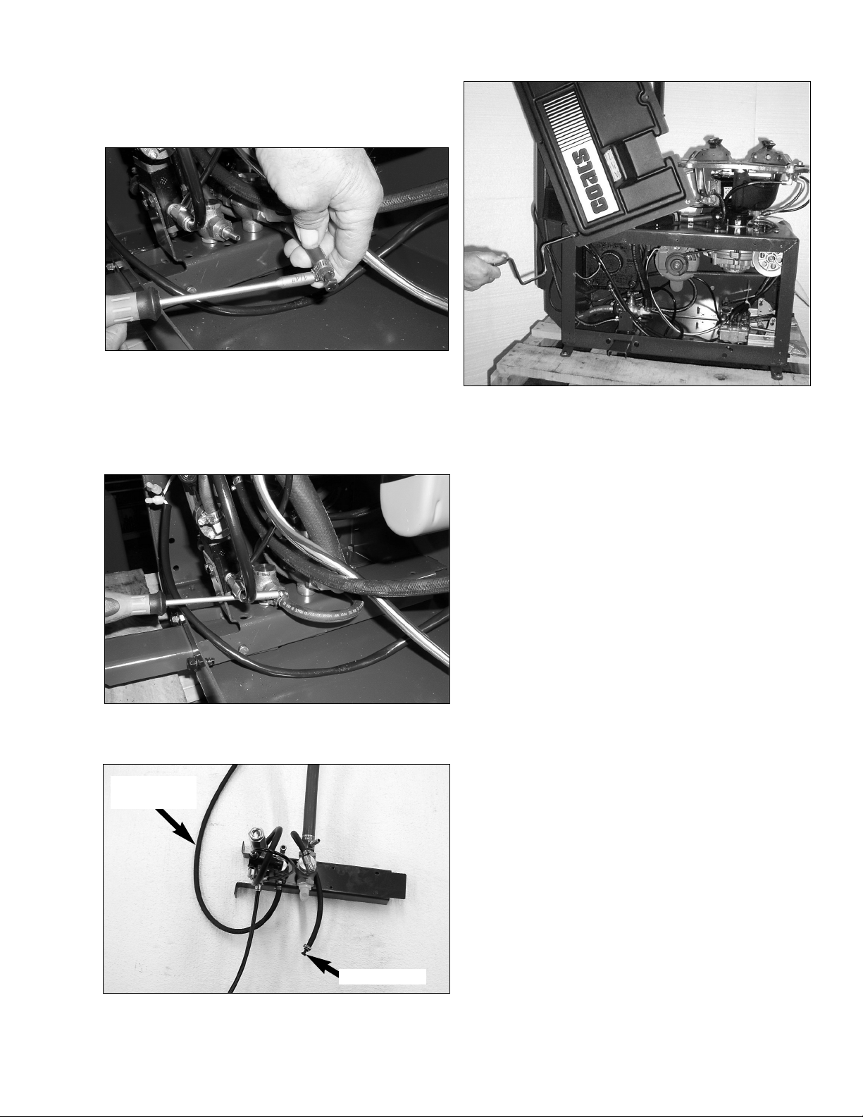
Converting Standard COATS®9010 or 9024
Tire Changer To Nitrogen
Before beginning this modification or attempting any
maintenance, remove the electrical power and air
source from the machine; also, bleed off any stored
compressed air by exhausting through the air blast foot
valve.
1. Tools required: two six inch adjustable wrenches.
2. On the right rear of the machine, locate the filter-
lubricator system and note the tee fitting on the input
side of the filter. The clear tubing represents the inflation system inside the tire changer and the black tube
represents the operational system of the machine.
3. Using the wrench to move the tube furrel toward
fitting, pull out on the clear plastic tube and remove
from the ELL fitting.
4
Page 5

4. Next, remove the ELL fitting and replace with the
1/4-inch NPT pipe plug fitting from the kit.
5. Next, install the clear plastic tube to the ELL.
Install a quick coupling fitting as required for connecting
to nitrogen. Connect the nitrogen supply and observe
the input pressure in the surge tank from the gauge
mounted on top of the tank. If the pressure exceeds
150 PSI, a pressure regulator must be added to prevent
the pressure relief from continuous activation caused
by the over pressure.
Pressure Gauge on Surge Tank
Nitrogen connection without regulator.
6. A pressure regulator to reduce the input nitrogen
pressure is available from COATS as p/n 8183424 or
one can be purchased from “Grainger” as p/n 4ZM14
(0-150 PSI adjustable). After installing the regulator,
adjust the pressure for a reading of 145 PSI on the
surge tank gauge.
A pressure regulator is directional sensitive
and must be installed correctly to adjust
pressure.
Nitrogen connection with in-line regulator.
7. Reconnect the air pressure supply to the machine
and the nitrogen supply to the machine and inspect for
leaks. If no leaks exist, test the machine for full function
before returning the machine to operation.
5
CAUTION
Page 6

Converting Standard COATS®40-50 Tire
Changer To Nitrogen Tire Inflation
Before beginning this modification or attempting any
maintenance, remove the air source from the machine;
also, bleed off any stored compressed air by exhausting
through the air blast foot valve.
Tools Required: Speed Handle, 3/8-inch Socket, 9/16inch socket, Spinner Handle 1/4-inch, Knife, 12-inch
Adjustable Wrench.
1. To start, remove both the front and rear side panels from the machine. This requires the speed handle
and the 3/8 inch and the 9/16 inch sockets.
2. On the front side of the machine, remove the inflation pedal by rotating the pedal upward and sliding to
the left.
3. Remove the nylon tube from the repeater valve by
pressing the brass tube furl toward the fitting and
pulling outward on the nylon tube. The opposite end of
this tube is attached to the 1/4-inch brass poppet inflation valve.
4. With an adjustable wrench, loosen and remove the
nut holding the top 1/4-inch brass inflation valve. Next,
remove the nut holding the lower 3/4-inch inflation
valve. Note that each valve has a spacer between the
chassis and the valve; take care not to misplace these
as they must be used when reinstalling the valves.
6
Page 7

5. From the back side of the machine, manipulate the
1/4-inch valve through the access opening. Next, cut
the 1/4-inch rubber hose supplying air to the valve. This
hose is between the 1/4-inch brass valve and the 3/4inch brass valve.
6. Using the 1/4-inch bolt (from kit), insert it into the
cut hose and with the hose clamp (from kit) secure the
bolt inside the hose. This will prevent air escaping at the
3/4-inch valve.
7. With wrenches, remove the cut hose from the
valve fitting. Next, install the new length of hose from
kit into the valve with clamp (from kit) and tighten.
Route the opposite end of the hose to the end of the
machine for connection to the nitrogen supply service.
8. Next, reposition the 3/4-inch valve with spacer and
install the retaining nut; do not over tighten the nut.
Next install the 1/4-inch valve with spacer and route the
black plastic hose as before to the foot valve end of the
machine.
9. Reattach the black plastic hose to the repeater
valve.
7
Page 8

8184554 01 01/05 © Copyright 2004 Hennessy Industries and COATS All Rights Reserved Printed in USA
10. Replace both side panels. Install a quick coupling
fitting as required for connecting to nitrogen.
11. Reconnect the air pressure supply to the
machine and the nitrogen supply to the machine and
inspect for leaks. If no leaks exist, test the machine for
full function before returning the machine to operation.
 Loading...