

Page 1
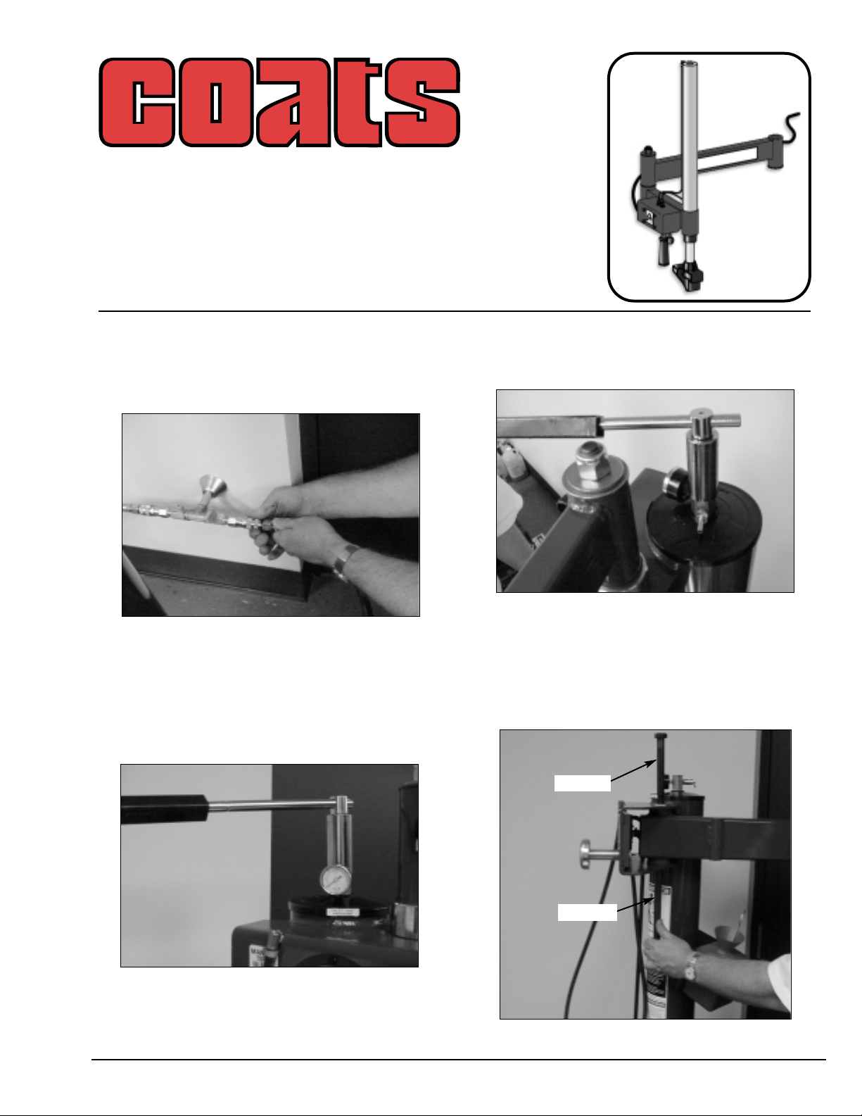
1. Before beginning any work, clear the area and
position the machine for easy access. Disconnect all
power sources, both air and electricity inputs. Allow
any stored air in the reservoir to escape by depressing the inflate valve.
2. Verify the stored air pressure is zero by observ-
ing the air pressure gauge on top of the tower. (see
photo). Next with a 1
1
/16-inch socket wrench remove
the manifold with the gauge and safety valve.
3. Next install the included manifold with the
gauge and safety valve plus a barbed hose fitting.
Tighten until the barbed fitting is located as shown in
photo.
4. Next, remove the nut on the bolt supporting the
swing arm pivot system. With the new long bolt
(10
3
/4-inches) push the old bolt out with the new bolt.
Make sure the small washer is on the head of the
new bolt.
Robo-Arm™ Kit 8184045
Installation Instructions
with Parts Identification
For use with COATS Model Series Tire Changers
COATS, Inc. • Hennessy Industries • 1601 J.P. Hennessy Drive, LaVergne, TN 37086-3565
(800) 688-6359 • (615) 641-7533 • (615) 641-5104 FAX
®
Figure 2
Figure 3
Figure 1
Figure 4
Old Bolt
New Bolt
8184060 04 04/01
Kit 8184045
Page 2
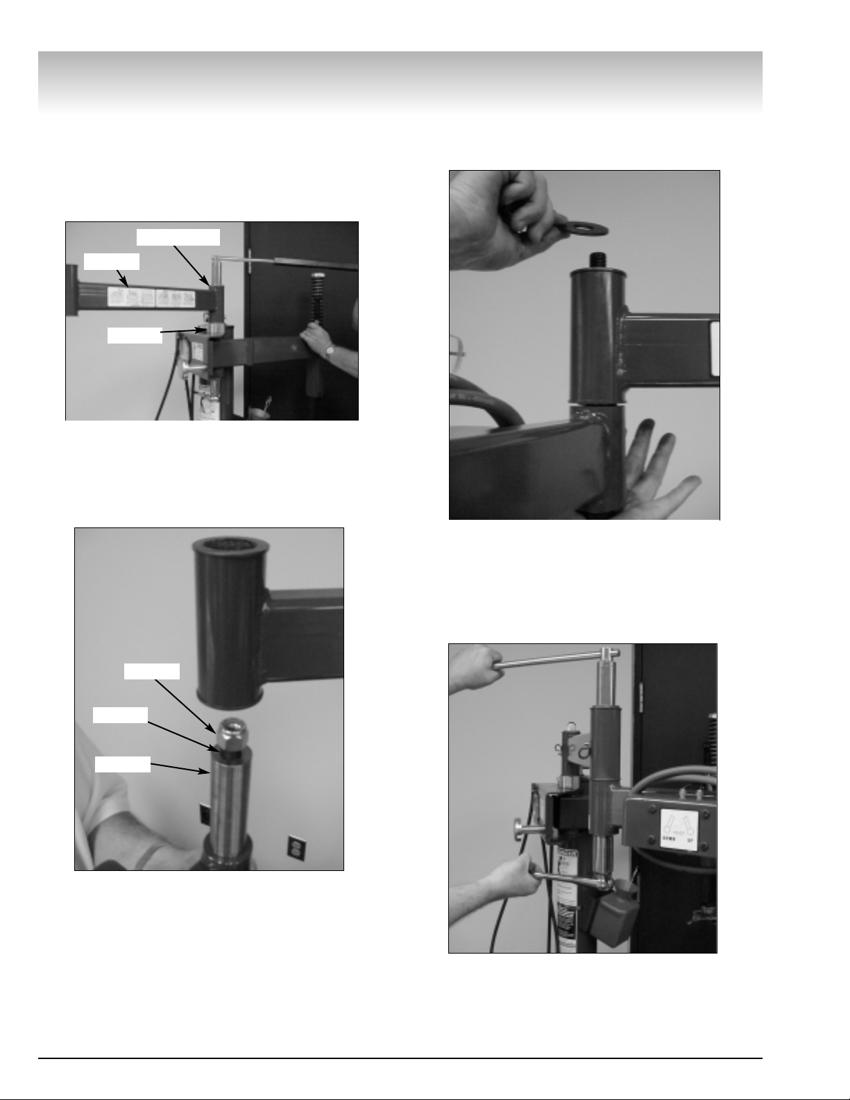
5. Next, install the large plated spacer, the swing
arm (note position of the decal) with pivot pin spacer,
and the lock nut. Next, using large wrenches, tighten
the assembly to 240 ft. pounds torque (very tight).
Even though the bolt is very tight, the assembly
should rotate easy.
6. Next, locate arm with cylinder, install seven inch
bolt with head through the bottom side, slide pivot
pin over bolt and attach nut with only one turn.
7. Slide the cylinder arm through the swing arm
bushing, hold in position, remove nut and place
washer over bolt threads and assemble nut to bolt.
8. Next using large wrenches, tighten the assem-
bly to 240 ft. pound torque (very tight). Again, even
though the bolt is very tight, the assembly should be
free to rotate.
Robo-Arm™
2 • Robo-Arm™ Kit Installation
Figure 5
Figure 6
Figure 7
Figure 8
Spacer
Nut
Bolt
Pivot Pin
Large Washer
Decal
Page 3

9. Next, unwrap the red hose from valve, guide
through hose clamps; and, with the hose pushed
over the barbed fitting, tighten the screw type hose
clamp.
Next, reconnect the air pressure source and check
for leaks. Cycle the cylinder on the Robo-Arm™ several times to understand function.
10. For installing bead roller assist tool, attach the
rectangular tube in the kit to the “Bead Loosener
Arm”. Use the existing hole in the bead loosener
arm. Position the tube at a slight angle and tighten.
11. Next will be the installation of the duckhead
bracket. Start by removing the bolt in the bottom of
the vertical slide bar. This bolt is very tight; use caution when loosening.
12. Next install the bracket to the vertical slide
using the hex bolt; discard the washer. Note that the
metal duckhead is shown; the plastic duckhead can
be substituted for the metal duckhead.
Robo-Arm™
Robo-Arm™ Installation • 3
Figure 9
Figure 10
Figure 11
Figure 12
Bracket
Page 4

Robo-Arm™
8184060 04 04/01 © COPYRIGHT 2000 HENNESSY INDUSTRIES AND COATS ALL RIGHTS RESERVED PRINTED IN U.S.A.
""
Lubricate Pin with Grease at
Assembly with Arm.
""
Part
Item No. Qty. Description
1 8120408 4 Hex HD Cap Screw 1/4-20 x 1 3/4"
2 8183638 4 Stand Off Spacer
3 8105615 2 1/4" NPT Muffler
4 8101428 2 1/4" Hose Clamp
5 8181996 3 1/4 NPT x 1/8 Tube St. Fitting
6 8109481 4 1/4 NPT x 1/8 NPT Fitting, Red
7 8183642 1 3 Position Hand Oper. Valve
8 8000376 1 1/4" x 90˚ Brass
9 8184243 1 Hose 1/4" ID x 49" Red
10 8181038 1 Swing Arm Pivot Pin
11 8183630 1 Short Arm Assem. W/C
12 8183679 1 1/8" x 5" Tube
14 8183639 1 7/8" Dia Handle Grip
15 8183703 1 3/4-10 x 10 1/2" Hex HD Cap Screw
16 8181997 1 90˚ Elbow 1/8" x 1/8" Fitting
17 8183680 1 1/8 Dia x 27" Tube
18 8182016 2 3/4-10 Hex Nylock Lock Nut
Part
Item No. Qty. Description
19 8184226 2 Grease Fitting
20 8182044 2 Neoprene Cushion Clamp
21 8183644 1 Cyl Assem 2" Dia x 18" Stk
22 8183683 1 Information Decal
23 8100994 4 .81 ID x 2.00 OD x .156 Washer
24 8184208 1 Pivot Pin/Spacer
25 8183649 1 1/4-20 x 5/16" Soc Hd Set Screw
26 8183637 1 Ext. Retaining Ring 2"
27 8181017 1 1/2" Dia Steel Ball
28 8183641 1 Plastic Hold Down Foot
29 8005563 1 1/4" Dia x 1 1/2" Roll Pin
31 8183626 1 Rear W/C Arm Assembly
32 8108968 1 Air Gauge
33 8183434 1 Manifold/Gauge Protector
34 8104968 1 Safety Valve
35 8000378 1 1/4 NPT x 1/4 Hose St. Fitting
36 8183635 1 3/4-10 x 1/4" Hex Hd Cap
Parts Identification
Torque to 240 ft. lbs.
 Loading...