

Page 1
SPA HEATER
INSTALLATION, OPERATION
AND MAINTENANCE
MODELS:
ST SERIES
5.5 & 11kW
240V SINGLE PHASE
BEFORE YOU BEGIN
CHECK ALL ELECTRICAL CONNECTIONS TO ALL COMPONENTS
WITHIN THE HEATER FOR TIGHTNESS. CONNECTIONS CAN
BECOME LOOSE DURING SHIPMENT AND HANDLING.
CAUTION
THE ELECTRICAL INSTALLATION MUST BE IN ACCORDANCE
WITH ARTICLE 680 OF THE NATIONAL ELECTRICAL CODE.
WARNING
Only qualified personnel, as defined by National Electric Code Article
100, should install and maintain this equipment. Unauthorized
alteration or improper maintenance of this unit may release the
manufacturer from any warranty claims. The installation must be in
accordance with the instructions in this manual and applicable local
plumbing and electrical codes.
Publication 10-2012
Page 2
1.0 DESCRIPTION
2.2 ELECTRICAL INSTALLATION
Coates Spa Heaters are intended for use on spas or
hot tubs having a forced water circulation system.
The water flow through the heater should be at least
15 GPM but should not exceed 80 GPM. Higher
flow may damage the heater. An external bypass
should be installed to limit the flow to within this
range.
2.0 INSTALLATION
Only qualified personnel, as defined by National
Electric Code Article 100, should install and
maintain this equipment. Unauthorized alteration
or improper maintenance of this unit may release
the manufacturer from any warranty claims. The
installation must be in accordance with the
instructions in this manual and applicable local
plumbing and electrical codes.
WARNING
CHECK ELECTRICAL CONNECTIONS TO ALL
COMPONENTS within the heater for tightness.
These can become loose during shipment and
handling.
2.1 PHYSICAL PLACEMENT
The Coates Spa Heater is suitable for indoor or
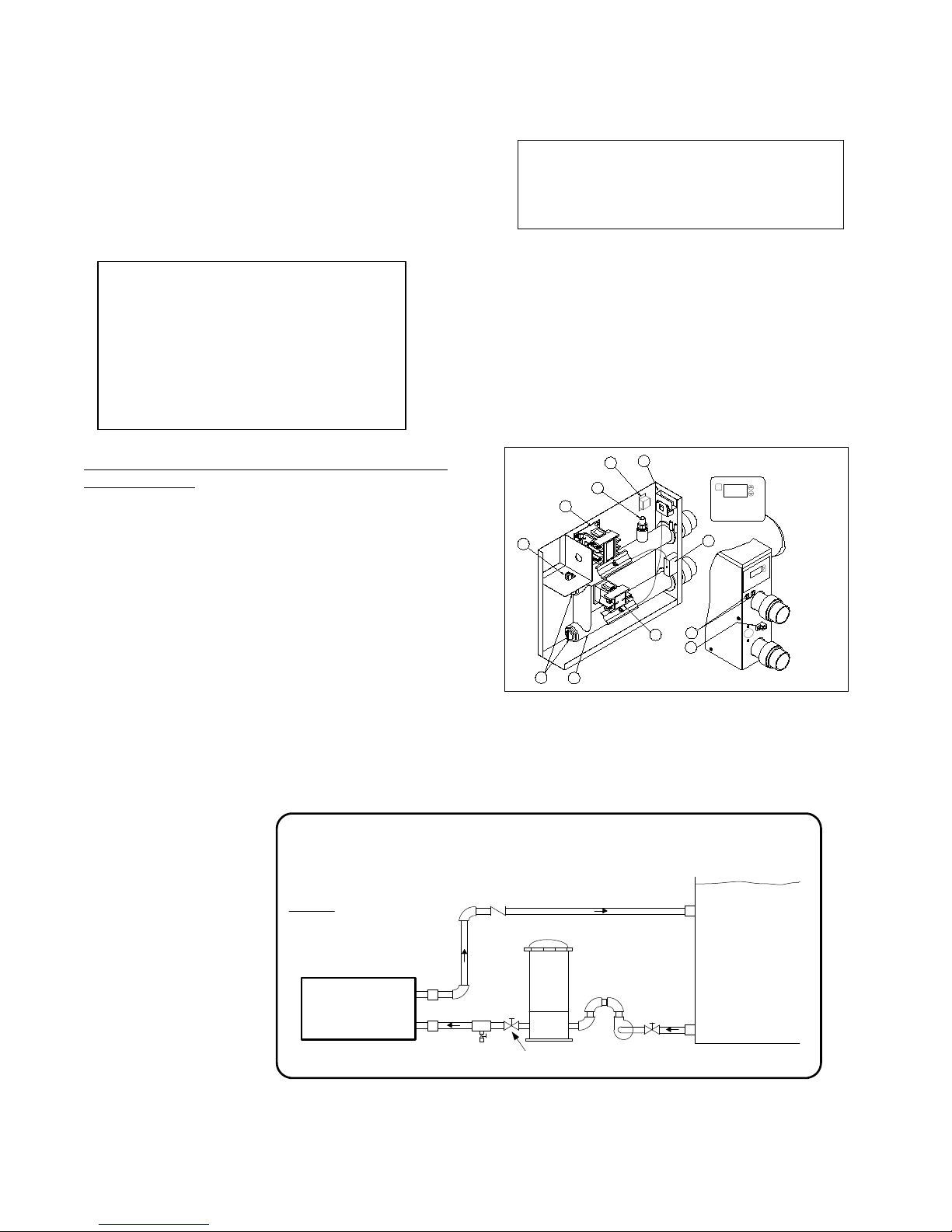
outdoor installation. See Figure 1 for piping
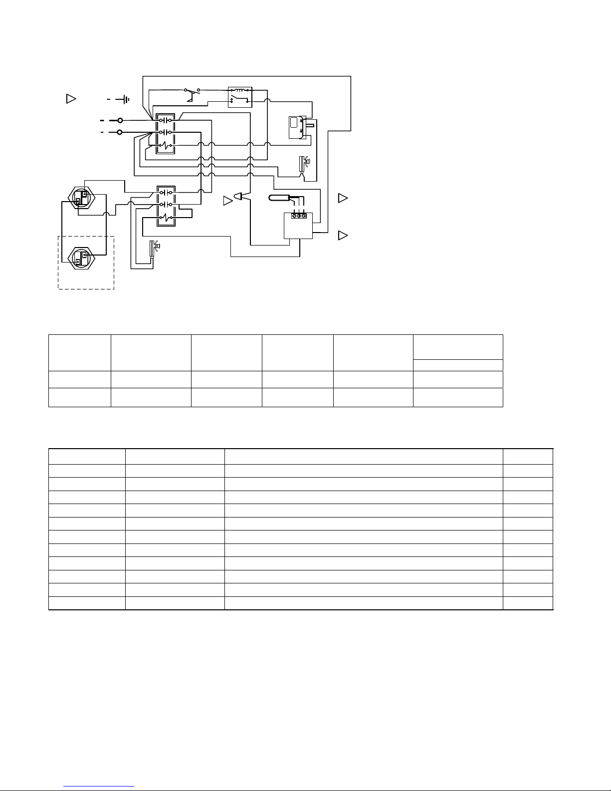
connections and Figures 3A or 3B for electrical
connections. The heater should be securely
mounted to a smooth, flat surface. It may be
conveniently located next to the filtration equipment.
Leave minimum clearances of 9 inches on the
left for element removal, 12 inches on the front
for maintenance, 6 inches on the back for
service entrance and the right side will be
determined by the plumbing configuration used.
The electrical supply power must be single phase,
CAUTION
THE ELECTRICAL INSTALLATION MUST BE IN
ACCORDANCE WITH ARTICLE 680 OF THE
NATIONAL ELECTRICAL CODE (NEC).
2 wire, 240 VAC. The supply must be protected
by a ground fault circuit interrupter (GFCI) in
accordance with NEC Article 680. An electrical
disconnect with over-current protection must be
provided. An insulated ground conductor must be
provided. See Figures 3A or 3B and Table 1 for
supply wire and circuit sizing. A lug has been
provided for attachment of the BONDING wire per
the NEC Article 680-22, (a)(4). This lug is located
between the inlet and outlet pipes of the heater
2
5
6
10
MENU
ELEM. FLOW
4
RESET BUTTON
°F HEATING°C
TEMPERATURE
CONTROL
F
U
N
E
M
E
T
O
L
F
.
M
E
L
E
T
E
S
E
R
G
N
I
T
A
E
H
C
E
R
U
T
A
L
R
O
E
P
R
T
M
N
O
C
W
T
E
L
T
U
O
T
E
L
N
I
INLET/OUTLET PV C UNIONS
ID ACCEPTS 1 1/2 PVC PIPE
OD ACCEPTS 2" PVC FITTINGS
CSTILL1C
3
1
9
1
NOTE: TEMP
CONTROL BULB
ON LOWER LEG;
TEMP LIMIT BULB
ON UPPER LEG
8
7
Coates Spa Heater Assembly
Figure 2 – Coates Spa Heater Assembly.
Refer to Table 2 for part description.
DO NOT INSTALL ANY SHUT-OFF
** NOTICE **
NO PRESSURE RELIEF
VALVE IS SHIPPED WITH
THIS HEATER AND NONE
IS REQUIRED PER UL
STD 1261. DO NOT
INSTALL SHUT OFF
VALVE ON DISCHARGE SIDE OF
HEATER. A SWING CHECK
VALVE IS PERMITTED.
Exception
pressure relief valve is installed
between the heater and valve , the
valve may be of the shut-off (ball or
gate) type.
VALVE BETWEEN THE
HEATER AND POOL OR
SPA. A CHECK VALVE IS
COATES POOL
ACCEPTABLE AND IN
ACCORDANCE TO UL STD
1261 REVISED JULY 1983.
CAUTION
: If a 30 psi (2.1 Kg/cm2)
HEATER
FIGURE 1 – PIPING DIAGRAM
DRAIN
VALVE
CHECK
VALVE
FILTER
BALL OR GATE
VALVE
PUMP
BALL OR GATE
VALVE
POOL
or
SPA
Page 3

3.0 CONTROL PANEL
A. INDICATOR LIGHTS
The control has two indicator lights. The lights are
as follows:
STATUS LIGHTS
LIGHT DESCRIPTION (when Illuminated)
FLOW Sufficient water flow through heater.
ELEMENT Heating elements are powered.
B. DIGITAL THERMOSTAT CONTROL
For heaters equipped with a digital thermostat. The
digital thermostat control which measures the
temperature of the water as it enters the heater has
a MENU button, up and down adjustment buttons,
and an LED display. The desired water temperature
(set point) is controllable between 40°F and 104°F
(5°C and 40°C). The set point may differ from the
actual water temperature at the pool or spa due to
heat loss in the piping.
MENU:
The MENU button cycles through the three menu
items: Measured Water Temperature (default), SET
POINT and °F/°C.
ADJUSTING THE SET POINT:
Press one of the following buttons; MENU,
The display will momentarily blank and then the
current set point will be displayed. Press the
button to change the set point. Hold the button
down for rapid temperature changes.
The set point will be saved and the display will return
to the measured temperature after two seconds of
inactivity.
OPERATION:
In the measured temperature mode, the water
temperature in the heater is displayed. The LED
corresponding to the current temperature scale will
be illuminated. If the heater is calling for heat the
HEATING LED will be illuminated.
FAHRENHEIT TO CELCIUS:
Press the MENU button twice and the current
temperature scale will be displayed ( F or C ). Press
or buttons to toggle between F and C.
the
The temperature scale will be saved and the display
will return to the measured temperature after two
seconds of inactivity.
or .
or
ERROR CODE:
The display will read “Err” when it detects a
problem with the temperature sensor. This can be
caused by a faulty sensor or a loose connection
between the sensor and the temperature
controller.
3.1 CAUTIONS AND WARNINGS
1. Be sure to check all cautions and
warnings in this manual and as displayed
on the heater labels before operating or
performing and maintenance on these
heaters.
2. Do not remove the heater cover while
electrical power is applied to the heater.
Power must be interrupted at the heater
supply circuit breaker or disconnect
switch.
3. The MIN setting on the temperature
control dial is an OFF position. The heater
will not operate at this setting regardless
of water temperature.
3.2 STARTING THE HEATER
- CAUTION -
Do not operate heater without water.
1. Ensure that heater case is properly
grounded, and bonded.
2. Fill the system with water and start the
circulating pump.
3. Turn on electrical power at the heater
supply circuit breaker.
4. Set the temperature control to desired
water temperature and adjust accordingly
after the temperature has stabilized. DO
NOT EXCEED 104°F.
3.3 STOPPING THE HEATER
Turn off electrical power at the heater supply
circuit breaker before stopping the circulating
pump.
4.0 MAINTENANCE
1. Keep the heater clean.
2. If high temperature causes the limit
thermostat to cut off the electrical power,
turn off power at disconnect switch and
determine the cause before resetting the
switch. A water temperature drop is
required to allow resetting of the manual
reset high temperature limit.
3. If leaks develop in the heater or
connecting piping, shut down the heater
and repair defective connections.
4. If heating elements are removed for
replacement, use only Coates elements,
see Table 2.
Page 4
2
HEATING
ELEMENT - 1
ELEMENT - 2
GROUND
LINE 1
LINE 2
BLK # 8
HEATING
12411ST
RED # 8
RED #8
BLK #8
RED
BLK
BLUE
RED
CON 1
COIL
CON 1
COIL
“ELEMENT”
LIGHT
PL1
FLOW
RED # 8
BLK # 8
RLY
BLUE
240V
COM
NO
RED
BLUE
BLK
BLK
1
TEMP.
RED
MODEL 12406ST / 12411ST
CONTROL
Wiring Diagram
TABLE 1
TC
“FLOW”
LIGHT
TEMP
PROBE
PL2
CNO
J3
RED
240V
B
WR
J9
J4
TEMP. LIMIT
CONTROL
RED
J1
AC
J2
AC
HTL
HTL: HI-TEMP CUT OFF “MANUAL RESET”.
TC: TEMPERATURE CONTROL - THERMOSTAT.
ELM 1 - 2: HEATING ELEMENT(S).
CON 1: CONTACTOR, 2 POLE, 50 AMP RES.
PL 1: PILOT LIGHT “ELEMENT”.
PL 2 PILOT LIGHT “FLOW SWITCH”.
FLOW: FLOW SWITCH
RLY: FLOW RELAY
FACTORY SPLICED LEADS ARE PROVIDED FOR
1
CONNECTION TO CUSTOMER SUPPLIED AUXILIARY
CONTROLS. i.e. REMOTE THERMOSTAT OR HEATER
“ON/OFF” SWITCH. SEE YOUR DEALER FOR FURTHER
INFORMATION.
INSULATED GROUND CONDUCTOR, COPPER ONLY.
2
MUST BE SAME SIZE AS THE SUPPLY WIRING, BUT
NOT LESS THAN # 12 AWG.
MODEL NO. HEATER
KW/VOLT
RATING
NO. & KW OF
HEATING
ELEMENTS
HEATER
CURRENT
RATING
RECOMMENDED
CIRCUIT RATING
RECOMMENDED
SUPPLY WIRING
COPPER @ 60° C
12406ST 5.5 @ 240VAC 1 @ 5.5 KW 23 AMPS 30 AMPS #10 AWG
12411ST 11 @ 240 VAC 2 @ 5.5 KW 46 AMPS 60 AMPS #4 AWG
TABLE 2
ITEM PART NUMBER DESCRIPTION QTY
1 – CON1 21000100 CONTACTOR, 2P, 50 AMP, 240VAC 2
2 - TC 22002150 DIGITAL TEMPERATURE CONTROL 1
3 - FLOW 23000105 FLOW SWITCH, 20 GPM 1
4 - HTL 22003820 HIGH TEMPERATURE LIMIT, MANUAL RESET 1
5 - RLY 21006010 FLOW RELAY, 30AMP, 240V 1
6 – PL1,2 29034620 PILOT LIGHTS for ELEMENT and FLOW 2
7 62002615 VESSEL ASSEMBLY, STAINLESS STEEL 1
8 20005061 HEATING ELEMENT, 5.5KW, 240 VOLTS *
9 29020025 GROUND LUG, LA-2 1
10 29020035 BONDING LUG, SAU-70 1
11 32705010 UNION ASSEMBLY 2
* SEE TABLE 1 FOR ELEMENT QUANTITY
When ordering parts from your dealer, provide the model number and serial number of your heater.
Page 5
WARNING:
Only qualified personnel should attempt maintenance on this equipment. (NEC Article 100)
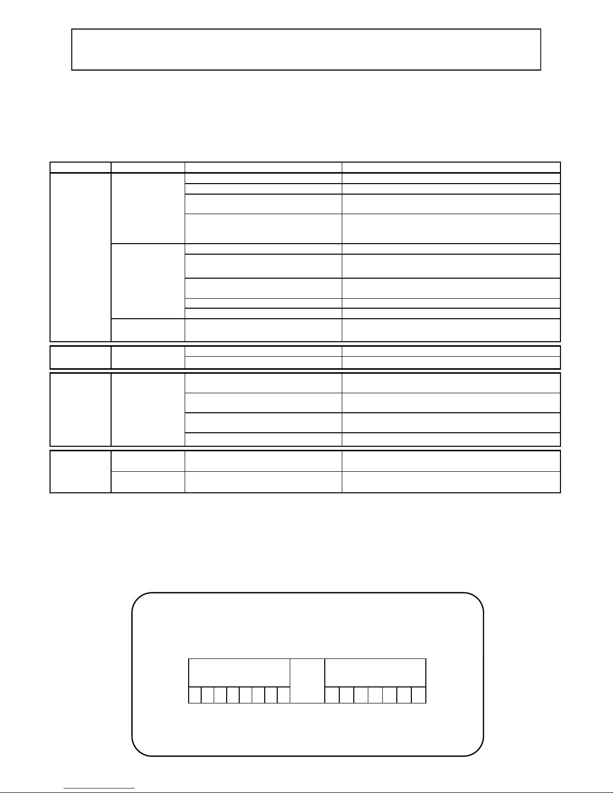
HEATER TROUBLE SHOOTING GUIDE
- CAUTION -
This heater incorporates 240 volt electrical circuits.
Do not open the case unless unit is disconnected from electrical power.
Use only manufacturer's parts, or UL listing and warranty may be void.
PR O B L E M IND IC AT ORS POSSI BLE CAUSES ACTION
No Heat
Insufficient Heat
High Limit
RESE T Tr ips
No lights
Flow light
Element light
Flow light
Element light
Flow light
Element light
Flow light
Element light
ON
ON
ON
ON
ON
No Power to heater Check Circuit Break er "ON".
Insufficient Flow Check that pump is running and filter is clean.
Flow Switc h Inoperative Use Ohm meter to c heck continuity across sw itch while
Flow Relay Inoperative Use Ohm meter to c heck continuity across NO and COM
Hi-Limit Reset T ripped Push "Reset" button
OFF
High Limit swit ch inoperative Use Ohm meter to c heck continuity across sw itch.
Temp Control inoperative or set too low Adjust control higher or replace as required.
Contactor (upper) inoperative Replace upper contactor
Contactor (lower) inoperative Replace lower c ontactor
Heating Element(s) inoperative Replace Element(s) as required.
ON
Heater too small for Spa Check heater sizing requirement of Spa.
ON
One element inoperative on 11KW model Replace Element as required.
Temperature control inoperat ive, water
overheats in Spa.
OFF
Flow Switc h not turning off heater when
pump/flow stops
Heater subjected to high ambient
temperature (i.e. Direct sunlight)
High Limit swit ch inoperative Replace High Limit Switch
pump is running. Replace Flow Swit ch if Open.
terminals while pump is running. Replace Flow Switch if
Open.
Replace High Limit Switch if always open.
Check "HEATING" indicat or light on temp displ ay is "ON"
Replace Temperature Control.
Check flow switc h opens when pump is off. Replace as
required.
Cool Equipment room or shade heater from sun.
Wat er Temp
Greater than
setpoint
Flow light
Element light
Flow light
Element light
ON
ON
Thermostat out of calibration/inoperative Replace thermostat.
ON
External heat source (i.e. Solar Heating,
heat from the pump, etc.)
OFF
Turn off power to heater and verify problem continues.
Elements can be checked with an Ohm meter only when power is disconnected from heater and all wires have
been removed from the element terminals. Each element should read approximately 10.5 Ohms.
Ambient temperatures above 120°F will cause the high temperature limit to trip prematurely.
PROTECTING YOUR COATES HEATER
WITH PROPER WATER CHEMISTRY
Proper water balance is important to extending the life of your Coates
Heater. While pH control is critical, the control of alkalinity and calcium
hardness will protect against scaling and also help to prevent corrosion.
ACID
HEATER
CAN BE
DAMAGED
The correct level of sanitizer, pH, total alkalinity and calcium hardness will very, depending
on the type of pool (plaster, fiberglass or vinyl) and the chemical content of the fill water.
Water that is out of balance can damage your pool heater and void the warranty. This
CORROSIVE
WATER
0 1 2 3 4 5 6 7
heater is not for use in salt water pools.
IDEAL
RANGE
7.2-7.8
ALKALINE
ALKALINE
WATER
8 9 10 11 12 13 14
HEATER
CAN BE
DAMAGED
Page 6

IMPORTANT SAFETY INSTRUCTIONS
6
When using this electrical equipment, basic safety precautions should always be followed, including the
following.
1) READ AND FOLLOW ALL INSTRUCTIONS.
2) To reduce the risk of injury.
A) The water in a pool or tub should never exceed 104°F (40°C). A water temperature in excess of
104°F is considered unsafe for all persons. Lower water temperatures are recommended for
extended use (exceeding 10-15 minutes) and for young children. SEE “STARTING THE
HEATER” IN THE OPERATIONS & MAINTENANCE MANUAL FOR INST RUCTIONS ON HOW
TO ADJUST THE TEMPERATURE CONTROL.
B) Since excessive water temperatures have a high potential for causing fetal damage during the
early months of pregnancy, pregnant or possibly pregnant women should limit pool or tub water
temperatures to 100°F (38°C).
C) Before entering a pool or tub, the user should measure the water temperature at several occupant
locations using an accurate thermometer since the tolerance of water temperature-regulating
devices may vary as much as ± 5°F (± 3°C).
D) Alcohol, drugs or medications should not be used before or during pool or tub use since their use
may lead to unconsciousness with the possibility of drowning.
E) Obese persons and persons with a medical history of heart disease, low or high blood pressure,
circulatory system problems, or diabetes should consult a physician before using a pool or tub.
F) Persons using medication should consult a physician before using a pool or tub since some
medication may induce drowsiness while other medication may affect heart rate, blood pressure,
and circulation.
3) SAVE THESE INSTRUCTIONS.
---WARNING---
DANGER OF HYPERTHERMIA
Hyperthermia occurs when the internal temperature of the body reaches a level several degrees above
the normal body temperature of 98.6°F. The symptoms of hyperthermia include dizziness, fainting,
drowsiness, lethargy and an increase in the internal temperature of the body. The effects of hyperthermia
include:
a) Unawareness of impending hazard;
b) Failure to perceive heat;
c) Failure to recognize the need to exit pool or tub;
WARNING--- The use of alcohol, drugs or medications can greatly increase the risk of fatal
hyperthermia in pools and tubs.
d) Physical inability to exit pool or tub;
e) Fetal damage in pregnant women;
f ) Unconsciousness resulting in a danger of
drowning.
Page 7

THIS PAGE
INTENTIONALLY
LEFT BLANK
Page 8

LIMITED WARRANTY
The company extends this limited warranty to the original purchaser of a Coates Electric Spa Heater.
Coates warrants the electrical components* and wiring (excluding enclosure, enclosure parts, knobs and accessories) in this
new Spa Heater to be free from defects in materials and workmanship for one (1) year from th e provable date of purchase, or
eighteen (18) months from date of factory shipment, whichever occurs first. Coates further warrants the stainless
containment vessel to be free from defects in materials and workmanship for two (2) years from the provable date of
purchase or thirty (30) months from the factory shipment, whichever occurs first. Enclosure, enclosure parts, knobs and
accessories have no warranty whatsoever.
*Exception: Factory installed heating elements are warranted for ninety (90) days from the date of heater installation, or one
(1) year from date of factory shipment, whichever occurs first.
COATES will repair or replace at its option, defective component parts as explained above, during the warranty period
provided such parts are returned to the factory, freight prepaid. Factory authorization MUST BE OBTAINED under this
warranty before returning such defective parts.
Limited Warranty Does Not Cover
1. New products purchased outside the United States of America and Canada.
2. Uncrating, unpacking, set-up, installation and / or startup of this unit.
3. Adjustments to controls normally operated by consumer, purchaser or installer.
4. This limited warranty does not extend to any defect, malfunction or failure caused by, or resulting from improper
service, maintenance or repair, abuse, neglect, accident, corrosion caused by improper water chemistry or by
equipment that use salt to create a sanitizer, lack of water, or any other cause beyond the control of Coates
Heater Company, Inc. or to any product where the nameplate shall have been removed, altered, replaced, defaced or
rendered illegible.
5. This limited warranty is void if the Heater is used in a salt water system or under any extreme or unusual
corrosive condition for which stainless steel metals would not be recommended.
6. This limited warranty does not extend to the repair or replacement of defective components except at COATES or a
service facility authorized by COATES
IMPLIED WARRANTIES, WHEN APPLICABLE, SHALL COMMENCE UPON THE SAME DATE AS THE EXPRESS
WARRANTY PROVIDED ABOVE, AND SHALL, EXCEPT FOR WARRANTIES OF TITLE, EXTEND ONLY FOR
THE DURATION OF THE EXPRESS WARRANTY. SOME STATES DO NOT ALLOW LIMITATIONS ON HOW
LONG AN IMPLIED WARRANTY LASTS, SO THE ABOVE LIMITATION MAY NOT APPLY TO YOU. THE ONLY
REMEDY PROVIDED TO YOU UNDER AN APPLICABLE IMPLIED WARRANTY AND THE EXPRESS
WARRANTY SHALL BE THE REMEDY PROVIDED UNDER THE EXPRESS WARRANTY, SUBJECT TO THE
TERMS AND CONDITIONS CONTAINED THEREIN.
COATES SHALL NOT BE LIABLE FOR INCIDENTAL AND CONSEQUENTIAL LOSSES AND DAMAGES, UNDER
THE EXPRESS WARRANTY, ANY APPLICABLE IMPLIED WARRANTY, OR CLAIMS FOR NEGLIGENCE,
EXCEPT TO THE EXTENT THAT THIS LIMITATION IS FOUND TO BE UNENFORCEABLE UNDER APPLICABLE
STATE LAW.
SOME STATES DO NOT ALLOW THE EXCLUSION OF LIMITATION OF INCIDENTAL OR CONSEQUENTIAL
DAMAGES, SO THE ABOVE LIMITATION OR EXCLUSION MAY NOT APPLY TO YOU.
THIS WARRANTY GIVES YOU SPECIFIC LEGAL RIGHTS, AND YOU MAY ALSO HAVE OTHER RIGHTS
WHICH VARY FROM STATE TO STATE.
steel water
P/N 90007000 10-2012
HEATER COMPANY, INC.
Kent, WA 98035
P.O. Box 1750
 Loading...