

Page 1
300180
VANITY SET
ASSEMBLY INSTRUCTION
COASTER FINE FURNITURE
www.coastercompany.com
Page 1 of 4
7/22/2014
Page 2
ITEM: 300180
I. Bottom glass
ASSEMBLY INSTRUCTION
A s s e m b l y I n s t r u c t i o n
ASSEMBLY TIPS:
1. Remove hardware from box and sort by size.
2. Please check to see that all hardware and parts are present prior to start of assembly.
3. Please follow attached instructions in the same sequence as numbered to assure fast & easy
assembly.
Warning!
1. Don't attempt to repair or modify parts that are broken or defective.Please contact the store
immediately.
2. This product is for home use only and not intended for commercial establishment.
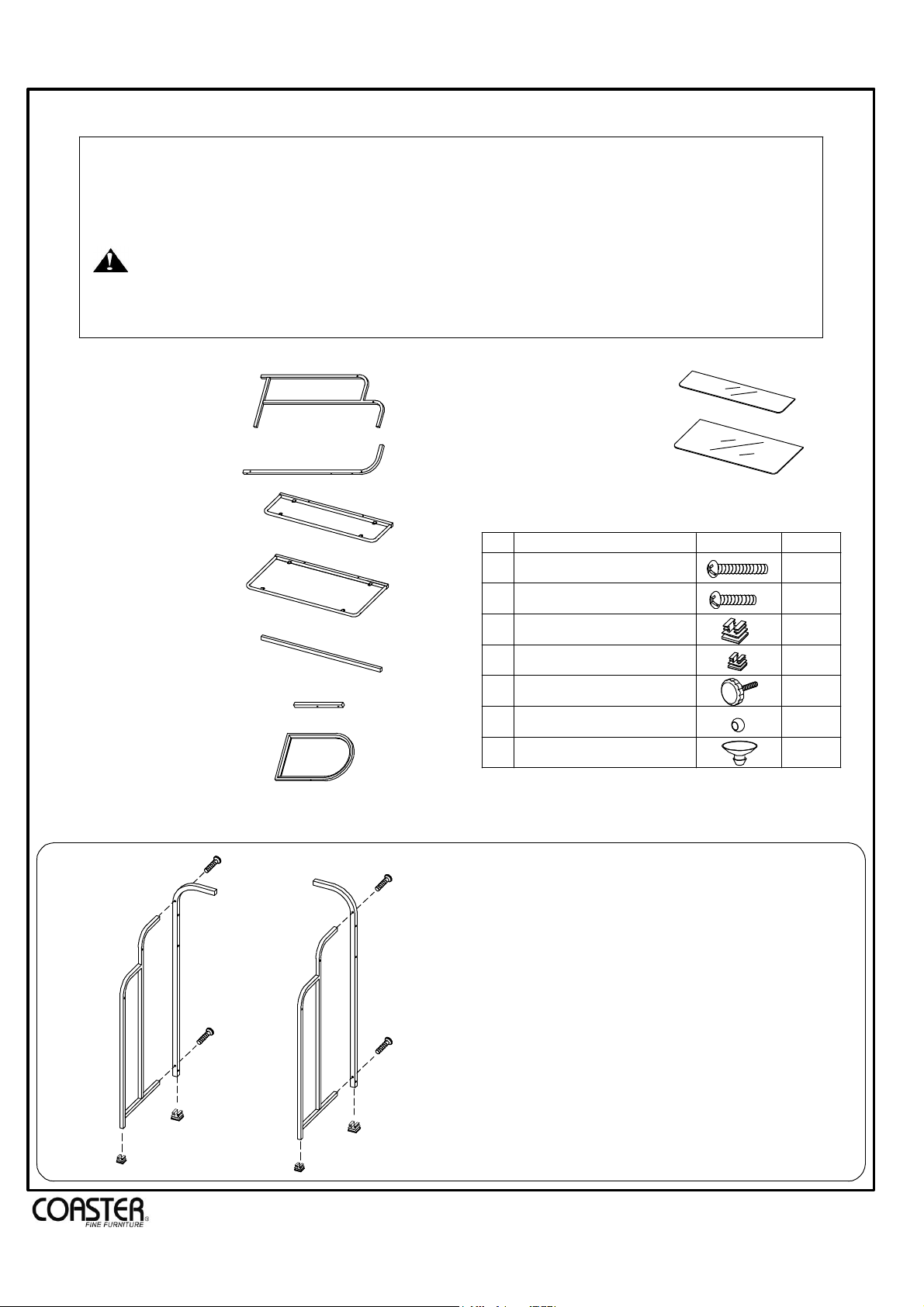
PARTS IDENTIFICATION FOR VANITY :
A. Vanity side frame
B. Rear side frame
C. Top glass frame
D. Bottom glass frme
E. Rear bottom crossbar
F. MIirror support
G. Mirror
2 PCS
2 PCS
1 PC
1 PC
1 PC
2 PCS
1 PC
H. Top glass
Z DESCRIPTION FIGURE
BOLT-LARGE
1
2
BOLT-SMALL
3
PLUG-LARGE
4
PLUG-SMALL
5
BOLT
6
CAP
GLASS PAD
7
A person assembles time for 30 minutes.
1 PC
1 PC
HARDWARE PACKAGE:
QTY
14 PCS
4 PCS
4 PCS
2 PCS
2 PCS
2 PCS
8 PCS
STEP 1
1
B
1
B
A
1
1
A
3
4
4
3
Page 2 of 4
Insert the plug-large (3) on the
rear side frame (B). Insert the plug
-small (4) on the vanity side frames
(A).Assemble the vanity side frames
(A) on the rear side frame (B) use
the bolt-large (1).
www.coastercompany.com
Page 3

ITEM: 300180
ASSEMBLY INSTRUCTION
STEP 2
1
2
1
F
3
1
C
1
E
3
1
F
1
2
1
1
Assemble the rear bottom crossbar (E)
on the side frame use the bolt-large (1).
Assemble the mirror support (F) on
the top glass frame (C) by the bolt-large
(1) and insert the plug-large (3) on the
mirror support (F). Final, assemble the
top glass frame (C) and mirror support
(F) on the side frames use the boltlarge(1) and bolt-small (2).
STEP 3
G
6
5
1
2
6
6
D
5
5
1
2
Assemble the bottom glass frame (D)
on the side frames use the bolt-large (1)
and bolt-small (2). Assemble the mirror
(G) to the mirror support (F) with the
caps (6) and bolts (5).
STEP 4
7
7
7
7
7
7
7
7
Insert the glass pad (7) on the on the
glass frame (C) and (D).
STEP 5
H
I
The glass (H) and (I) put on the glass
frame (C) and (D).
Page 3 of 4
www.coastercompany.com
Page 4

ITEM: 300180
ASSEMBLY INSTRUCTION
PARTS IDENTIFICATION FOR STOOL :
J. Back frame
K. Stool side frame
L. Cushion
M. Front crossbar
N. Seat crossbar
STEP 6 STEP 7
1 PC
2 PCS
1 PC
1 PC
2 PCS
8
J
HARDWARE PACKAGE:
Z
8
9
10
11
DESCRIPTION
BOLT
SCREW
PLUG-LARGE
PLUG-SMALL
8
FIGURE
QTY
10 PCS
4 PCS
2 PCS
2 PCS
8
8
8
8
K
8
M
10
11
K
11
10
Insert the plug-large (10) on
the back frame (J). And insert
the plug-small (11) on the stool
side frame (K) . Assemble the
stool side frame (K) on the
back frame (J) by the bolt (8).
Finial, assemble the front
crossbar (M) on the stool side
8
STEP 8
9
8
N
N
Assemble the seat
crossbar (N) on the front
crossbar (M) and stool
side frame (K) by the bolt
8
L
(8).
The cushion (L) put on the
9
9
9
seat crossbar (N) use the
the screw (9).
frame (K) by the bolt (8).
www.coastercompany.com
Page 4 of 4
 Loading...