


D/I Mux III System
For D/I Mux III Shelf and Common Equipment
USER’S MANUAL
30000-100-MOD
Issue C
November 2005

PUBLICATION RELEASE RECORD
Publication Number: 30000-100-MOD
Publication Name: D/I Mux III System User’s Manual
DATE ISSUE ECO NO. REASON FOR CHANGE
Aug 1997 A Combine CCU and AMCU. Add new
standard LIUs. Add FLIU. Revise to
Feature Group upgrade.
February
2002
November
2005
B 302-267 Delete FLIU Appendix.
Add new warranty page. New cover.
C Add new Power Supplies and Ringing
Generator

D/I MUX III User’s Manual
RELEASE NOTE December 2005
UPGRADED –24VDC Power Supply for D/I Mux III
Coastcom has released part number 30314-902, -24Volt DC Power Supply to replace 30314-101.
30314-902 Power Supply –24 VDC Redundant
The 30314-902 is a DC-to-DC converter used to power D/I Mux equipment from an external -24 VDC
input supply. Generates +/-12 and +/-5 volt outputs as well as failure alarm signals. Also provides
primary (-24v) power fusing. Can be used in a redundant or load sharing configuration when two power
supplies are installed. When configured with FXS cards order modular Ring Generator 30333-121. Can
be used in an 8/12/24 slot chassis. Replaces 30314-101.
RELEASE NOTE August 2005
UPGRADED POWER SUPPLY UNITS FOR D/I Mux III
In August 2005, Coastcom released upgraded power supply units for the D/I Mux III. The
following two new units replace part numbers 30338-102, 30315-105A, 30338-103A, and 30308102A.
30338-902 Power Supply -48 VDC Redundant
The 30338-902 is a DC-to-DC converter used to power D/I Mux equipment from an external -48 VDC
input supply. Generates +/-12 and +/-5 volt outputs as well as failure alarm signals. Also provides
primary (-48v) power fusing. Can be used in a redundant or load sharing configuration when two power
supplies are installed. When configured with FXS cards order modular Ring Generator 30333-101. Can
be used in an 8/12/24 slot chassis. Replaces 30338-102.
30315-505 Power Supply 120 VAC
An AC/DC self-contained single-slot power supply that provides all of the voltages necessary to
operate a D/I Mux III - except ringing voltage. When configured with FXS feature cards, order
modular Ringing Generator 30333-101. Provides +/-12, +/-5, and –48 volts. Can be used in an
8/12/24 slot chassis. Replaces a 30308-102A and the combination option of 30315-105A with
30338-103A. Cannot be used in combination with any other power supply.
i
D/I MUX III User’s Manual
RELEASE NOTE August 2005
RING GENERATOR MODULE FOR D/I Mux III
Introduction:
The 30333-101 / 121 Ring Generator provides internally generated ringing voltage for AC or DC
powered D/I Mux III shelves with 2W FXS and Smart Omni-Orderwire feature cards. The
30333-101 is a –48 volt powered unit while the 30333-121 is a –24 volt powered unit. It provides
up to 15 watts of continuous, superimposed (ringing voltage referenced to the negative battery
supply voltage) sine wave ringing voltage. The nominal frequency is 20 Hertz. A front panel
green LED indicates the presence of power to the card. A red LED and relay contact closure
indicate generator failure.
Installation:
The 30333-101 / 121 Ring Generator can be installed in any of three available areas of the D/I
Mux III shelf: Power Supply, Feature Card or UCOM (FDLP). In any of the three locations, it
automatically configures itself to operate. It can be installed or removed while the shelf is in
operation (hot swapped).
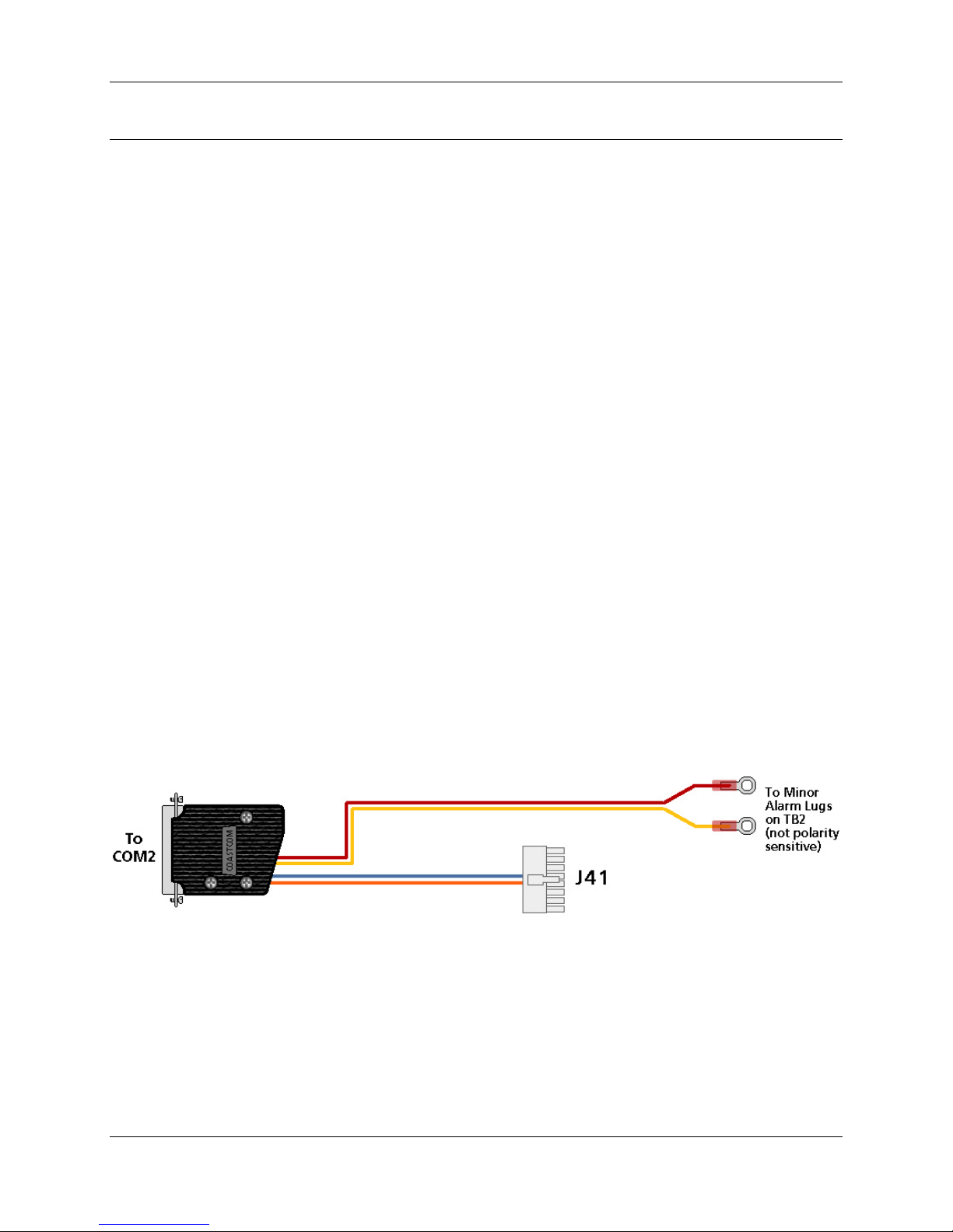
When installed in the UCOM location the accessory 30333-101-UC cable must be in place on
the back of the shelf to complete installation.
Installation of 30333-101-UC cable. Note: this cable is installed only when the Ring
Generator is located in the UCOM (FDLP) card slot. This cable is included with each 30333101 or 30333-121 unit.
At the rear of the shelf, plug the 30333-101-UC cable’s DB-25 male connector into the
DB-25 female UCOM2 location. Plug the white Molex connector into the mating shelf
Molex connector marked “AUX SHF I/F”. Unscrew the two screws marked “MNR ALM”
on the screw-down barrier strip. Install the two cable wires with the ring lugs. Put one
under each screw head. Connections for failure alarm are made at this location on the
barrier strip.
DB – 25 – M MOLEX WIRE
AMP 205208-1 Shell 39-01-2160 18 AWG
AMP 66570-3 Pins w/39-00-0039 Insulated
AMP 206478-3 Hood Female Pins Hookup,
Pairs
Twisted
ii

D/I MUX III User’s Manual
PIN-OUT CONNECTIONS
COLOR NAME PIN MOLEX
RED Alarm 1 2 -------------------------------------------------------------Æ Ring Lug
ORANGE +5V 3 ----------------------------Æ 11
YELLOW Alarm 2 4 -------------------------------------------------------------Æ Ring Lug
BLUE Ringer 6 ----------------------------Æ 6
Failure Alarm:
The 30333-101 / 121 provides relay contact closure (1 ampere maximum) for an external alarm
upon ringing generator failure. For Power Supply and UCOM locations, the connection location
is at the “Minor Alarm” terminals on the back of the D/I Mux III shelf. For a Feature Card
location the alarm contacts appear on the associated card slot’s DB-25 connector on the rear
panel, at pins 18 and 20.
Providing Ringing Voltage to Other Equipment:
The ringing voltage from the generator is available at the back of the shelf (marked “20 Hz”) for
connection to other applications (including D/I Mux III shelves) that require superimposed
ringing voltage. Be sure to securely ground all equipment using common ringing voltage to the
common ground connection on the D/I Mux III shelf that houses the Ring Generator. Care
should be exercised to keep the total continuous ringing load at or below the specified 15 watt
capability.
Attention should also be paid to overall loading – if an internal AC/DC power supply is installed
in the shelf with the 30333-101 Ring Generator and the unit also powers additional shelves –
the AC/DC power supply has to power all –48 Volt requirements in the shelf (CSU and talk
battery for FXS and Smart Omni Orderwire, etc.) along with powering the Ring Generator. If in
doubt regarding an application with high internal AC powered loading, contact Coastcom
application engineering (800-433-3433).
Caution:
This unit must be installed in a properly grounded D/I Mux III shelf.
Hazardous voltages are present on the Modular Ring Generator printed circuit card traces. Do
not operate this card on a card extender while operating in the shelf.
iii

D/I MUX III User’s Manual
Product Description
Coastcom's D/I Mux III™ is an intelligent drop-and-insert T1 multiplexer for voice, data, and
special service applications. It offers programmable software for monitoring and controlling
configurations, transmissions, alarms, and diagnostics. Intelligent channel cards permit
software access to individual circuits.
D/I Mux III accesses one or two T1 transmission lines, and interfaces up to 48 DS0 transmission
channels. Voice, data, video, and special services are provided in any combination within a D/I
Mux III. With the addition of Coastcom's 5-port Subrate Data Multiplexer (SDM) line cards, up to
120 data circuits are supported in a single multiplexer.
Special features of the D/I Mux III are its network compatibility, remote control capability,
integral T1 channel service unit, and standard copper wire Line Interface Units (LIU). Also, AC
power supply with ringer, redundant DC power supply option, and Automatic Loop Protection
Switching (ALPS™) as an optional feature for data protection in the event of transmission
failure. There are also several unique channel cards that offer services such as high quality
audio, links to other T1 systems, and on-line selectable high speed data.
All equipment specifications subject to change without notice.
iv

Specifications
Multiplexer Requirement
Model: D/I Mux III
Software Versions:
Common Control Unit (CCU) (30305-106/108): 8.1/9.1 (or above)
Previous CCU Feature Group: 6.0/8.0 (or above)
Common Control Unit (CCU) (30305-110) 1.8 (or above)
ALPS CCU (30305-109) 9.8 (or above)
Multiplexer Control Unit (MCU) (40305-103) 1.4 (or above)
Previous MCU Feature Group: 1.3 (or above)
Advanced Multiplexer Control Unit (AMCU) (40305-104) 1.8 (or above)
Line Interface Units Requirement
LIU Models: 30309-104/114
Design Compliance
Complies with applicable sections of AT&T publications 43801, 54018, 54075, 62310 and 62411
Complies with applicable sections of ANSI publications T1.403, and T1.107
Complies with regulatory standards:
FCC Part 15, Subpart B, Class A;
FCC Part 68
DOC CS-03
UL/CSA standards certified by CSA
Copyright© 1997 by Coastcom. All Rights Reserved. Printed in the United States of America. No Coastcom
document, or parts thereof, may be reproduced in any form without prior written permission from Coastcom except
where otherwise noted. The information in this manual is subject to change without notice. D/I Mux III, ALPS, and
T1M CSU/DSU are Trademarks of Coastcom
ACCUNET
®
and MEGACOM® are registered Trademarks of AT&T.
®
.

D/I MUX III User’s Manual
D/I Mux III User's Manual Organization
This D/I Mux III User's Manual is written for use by technical planners as well as operation and
installation personnel.
The D/I Mux III User's Manual is organized in the following order:
• System Overview and Modes of Operation
• Applications
• Installation
• Configuration and Operation
• Diagnostics
• Appendices
Coastcom recommends a thorough review of the content and organization of this manual. An extensive
table of contents provides easy access to installation and maintenance information. At each step of the
installation process, applicable procedures should be re-read carefully to ensure that the required tools
and components are available for successful installation and operation.
vi

D/I MUX III User’s Manual
REGULATORY INFORMATION
FCC NOTICE
Federal Communications Commission (FCC)
Part 15 Regulations For Telephone Equipment
NOTE: This equipment has been tested and found to comply with the limits for class A digital device, pursuant to
Part 15 of the FCC rules. These limits are designed to provide reasonable protection against harmful interference
when the equipment is operated in a commercial environment. This equipment generates, uses and can radiate
radio frequency energy and, if not installed and used in accordance with the instruction manual, may cause harmful
interference to radio communications. Operation of this equipment in a residential area is likely to cause harmful
interference in which case the user will be required to correct the interference at their own expense.
IMPORTANT: This product was tested for FCC compliance under conditions that included the use of shielded
cables and connectors between components. Changes or modifications to this product not authorized by the
manufacturer could void your authority to operate the equipment.
FCC Part 68 Requirements
Note: FCC Rules Part 68 require the following information to be included in this publication. Some of the information may
not be relevant to Coastcom equipment.
FCC regulations and telephone company procedures prohibit connection of customer-provided equipment to
telephone company provided coin service central office implemented systems. Connection to party line service is
subject to state tariffs. The applicable state public service commission should be contacted for information.
The telephone company may require disconnection of the user provided equipment in the event of a natural
disaster or other situation where damaged equipment could cause harm to the public telephone network.
Upon request, local telephone companies will provide information concerning questions about telephone lines,
such as how many pieces of equipment may be connected to it.
FCC Requirements for Connection of Systems to the Telephone Network
This equipment complies with the requirements of part 68 of the FCC rules.
Coastcom, Inc.
Coastcom Series of T1 Multiplexers
FCC Registration Number CRGUSA-17575-XD-N (with DSX Interface)
FCC Registration Number CRGUSA-60682-DD-N (with Internal CSU Interface)
Affixed to the equipment is a label containing the FCC registration number and the Ringer Equivalence Number
(REN) for this equipment. A list of the system interfaces, their Facility Interface Codes (FICs), and their Universal
Service Order Codes (USOCs) is provided. The telephone company has the right to request the following
information:
• Quantities and USOC numbers of the required jacks
• Sequence in which the trunks are to be connected
• FICs by position
• REN or service code, as applicable, by position
vii

D/I MUX III User’s Manual
The REN is used to determine the quantity of devices that may be connect to the telephone line and still
have assurance that all of those devices will ring properly when the applicable number is called. In most,
but not all areas, the sum of the RENs of all devices should not exceed five (5). To be certain of the
number of devices that may be connect to a line, as determined by the RENs, the local telephone
company should be contacted for information on the maximum REN for that calling area.
Regulatory Codes
Type of Interface USOC Jack
Connector
1.544 Mbps N/A 6.0p *
2 Wire Loop Start RJ21X 2.4 A (AC) 4.4 (DC) 02LS2
2 Wire Ground Start RJ21X 2.4 A (AC) 4.4 (DC) 02GS2
2 Wire E&M Type I RJ2EX 9.0F TL11E
2 Wire E&M Type II RJ2FX 9.0F TL12E
4 Wire E&M Type I RJ2GX 9.0F TL31E
4 Wire E&M Type II RJ2HX 9.0F TL32E
REN/Service Order
Code
Facility Interface
Code
OPS Class C RJ21X 9.0F OL13C
T1 (D4 Framing)** RJ48C 6.0P 04DU9-B
T1 (ESF Framing)** RJ48C 6.0P 04DU9-C
OCUDP RJ48S 6.0P 04DU5-56
Integral CSU
RJ48C 6.0P 04DU9-B
(D4 Framing)**
Integral CSU
RJ48C 6.0P 04DU9-C
(ESF Framing)**
Dual 4 Wire Deluxe RJ2GX 9.0F TL31E
Dual 4 Wire Deluxe RJ2HX 9.0F TL32E
Tandem T1 Unit N/A 6.0P 04DU9-BN
Tandem T1 Unit N/A 6.0P 04DU9-DN
Tandem T1 Unit N/A 6.0P 04DU9-1KN
Tandem T1 Unit N/A 6.0P 04DU9-1SN
All Rate OCUDP RJ48S 6.0P 04DU5-24
All Rate OCUDP RJ48S 6.0P 04DU5-48
All Rate OCUDP RJ48S 6.0P 04DU5-96
All Rate OCUDP RJ48S 6.0P 04DU5-56
* In some cases connection of this system requires filing an affidavit with the telephone company. When
connecting a system configured without an integral CSU, report the FCC registration number which contains the
equipment code "XD". An external FCC registered CSU is required to connect "XD" category equipment to the
1.544 Mbps public network. The Facility Interface Code is determined from the CSU.
viii

D/I MUX III User’s Manual
** In some cases, connection of this type of system requires filing an affidavit with the telephone company. When
connecting a system configured with an integral CSU, report the FCC registration number which contains the
equipment code "DD".
For metallic channel ports, please be aware that metallic pair services may not be available in all locations.
If any telephone equipment causes harm to the telephone network, the telephone company may temporarily
discontinue service to that line. If possible, the phone company will give advance notice of such discontinuance. If
advance notice is not practical, notice will be given as soon as possible. The telephone company will also advise
of the right to file a complaint with the FCC.
The telephone company may make changes in its facilities, equipment operations, or procedures that could affect
the proper operation of user equipment. Advance notice of changes should be given by the telephone company to
provide an opportunity to maintain uninterrupted service.
Repair Services
In the event equipment repairs are necessary, contact Coastcom for factory service. Customer repairs of
Coastcom equipment should be limited to module replacement and/or front panel servicing. For information,
contact:
Coastcom
1141 Harbor Bay Parkway
Alameda, CA 94502-6511
Tel: 800 433-3433
510 523-6000
FAX: 510 523-6150
Technical Support: 800 385-4689
ix

D/I MUX III User’s Manual
SAFETY AGENCY CERTIFICATIONS
Canadian Standards Association (CSA) certifies that D/I Mux III equipment meets the requirements of Underwriter’s
Laboratories (UL), as applicable, for the United States, and those of CSA, as applicable, for Canada.
When a DC powered system is purchased to be resold to another customer, or when purchased to be used as part
of another system, the system is referred to as a Rack Mounted Card Cage and is CSA Certified. Power supplies
and channel line cards which connect to the public telephone network are CSA Certified as components.
When a system is sold directly to a customer, and the system is configured with an internal AC power supply, for
customer premises applications, then the product is referred to as an Intelligent Multiplexer Card Cage and is CSA
Listed. To satisfy safety agency requirements, the user is advised that D/I Mux III equipment is “To be installed
only in Restricted Access Areas (Dedicated Equipment Rooms, Equipment Closets, or the like) in Accordance with
Articles 110-16, 110-17, and 110-18 of the National Electrical Code, ANSI/NFPA No. 70.”
INFORMATION FOR CANADIAN CUSTOMERS
Equipment Attachment Limitations
(Canada Only): CP-01, Part I, Section 10.1
NOTICE: The Canadian Department of Communications label identifies certified equipment. This certification
means that the equipment meets certain telecommunications network protective, operational and safety
requirements. The Department does not guarantee the equipment will operate to the user's satisfaction.
Before installing this equipment, users should ensure that it is permissible to be connected to the facilities of the
local telecommunications company. The equipment must also be installed using an acceptable method of
connection. In some cases, the company's inside wiring associated with a single line individual service may be
extended by means of a certified connector assembly (telephone extension cord). The customer should be aware
that compliance with the above conditions may not prevent degradation of service in some situations.
Repairs to certified equipment should be made by an authorized Canadian maintenance facility designated by the
supplier. Any repairs or alterations made by the user to this equipment, or equipment malfunctions, may give the
telecommunications company cause to request the user to disconnect the equipment.
Users should ensure for their own protection that the electrical ground connections of the power utility, telephone
lines and internal metallic water pipe system, if present, are connected together. This precaution may be
particularly important in rural areas.
CAUTION: Users should not attempt to make such connections themselves, but should contact the appropriate
electric inspection authority, or electrician, as appropriate.
CP-01, Part I, Section 10.2
NOTICE: The Load Number (LN) assigned to each terminal device denotes the percentage of the total load to be
connected to a telephone loop which is used by the device, to prevent overloading. The termination on a loop may
consist of any combination of devices subject only to the requirement that the total of the LN (Load Numbers) of all
the devices does not exceed 100.
x

D/I MUX III User’s Manual
TABLE OF CONTENTS
RELEASE NOTE UPGRADED POWER SUPPLY UNITS FOR D/I MUX III.............................................................I
RELEASE NOTE
Design Compliance ....................................................................................................................................v
Federal Communications Commission (FCC) ............................................................................................vii
Part 15 Regulations For Telephone Equipment.......................................................................................... vii
FCC Part 68 Requirements........................................................................................................................vii
FCC Requirements for Connection of Systems to the Telephone Network................................................vii
Repair Services..........................................................................................................................................ix
SAFETY AGENCY CERTIFICATIONS ......................................................................................................x
INFORMATION FOR CANADIAN CUSTOMERS ......................................................................................x
Equipment Attachment Limitations.............................................................................................................x
CHAPTER 1. SYSTEM OVERVIEW AND MODES OF OPERATION.....................................................................1
D/I Mux III Capabilities................................................................................................................................1
D/I Mux III Functions ..................................................................................................................................2
D/I Mux III Features....................................................................................................................................2
D/I Mux III Software Control .......................................................................................................................3
Network Communications Controller..........................................................................................................Error!
Bookmark not defined.
SNMP.........................................................................................................................................................4
Serial Line Internet Protocol (SLIP)............................................................................................................ 6
Gateway.....................................................................................................................................................7
Transmission Control..................................................................................................................................7
Transmission Channel Assignments ..........................................................................................................8
Maps...........................................................................................................................................................8
Timing and Clock Source ...........................................................................................................................9
Alarms and Monitoring................................................................................................................................9
Power Failure Alarm...................................................................................................................................10
Alarm LED Indicators, Alarm Cut-off, and Bypass......................................................................................10
Power Supply Failure Indicator LEDs.........................................................................................................10
Minor Alarm................................................................................................................................................10
Bypass........................................................................................................................................................10
Trunk Processing .......................................................................................................................................11
T1 Interfaces - CSUs..................................................................................................................................11
Lightning Protection....................................................................................................................................11
T1 Testing With the CSU............................................................................................................................11
Power Supplies...........................................................................................................................................12
D/I Mux III User Circuit Interfaces...............................................................................................................13
RING GENERATOR MODULE FOR D/I MUX III.........................................................................II
Remote Control with NCC............................................................................................................4
-48 Volt DC Power Supplies.........................................................................................................12
-24 Volt DC Power Supplies.........................................................................................................12
110 Volt AC Power Supply...........................................................................................................12
Circuit Features............................................................................................................................ 14
COMPONENT OVERVIEW 15
Shelves.......................................................................................................................................................17
xi

D/I MUX III User’s Manual
Shelf Backplane Connectors........................................................................................................18
Common Equipment Units and Line Cards ................................................................................................19
Common Equipment...................................................................................................................................19
Common Control Unit...................................................................................................................19
CCU Circuit Description ...............................................................................................................21
Advanced Multiplexer Control Unit (AMCU).................................................................................22
AMCU Motherboard Circuit Description ....................................................................................... 22
AMCU Sub-Board Circuit Description...........................................................................................26
Strobe Units .................................................................................................................................30
Line Interface Units......................................................................................................................32
T1 Interface Units ......................................................................................................................... 34
Power Supplies............................................................................................................................35
Line Cards..................................................................................................................................................35
Data Line Cards...........................................................................................................................35
Voice Line Cards..........................................................................................................................36
Digital Program Line Cards..........................................................................................................36
MODES OF OPERATION 37
Channel Bank Operation............................................................................................................................37
Loop Timing .................................................................................................................................37
Local Timing.................................................................................................................................37
Drop-and-Insert Operation..........................................................................................................................38
Recovered Timing........................................................................................................................38
Dual Channel Bank Operation....................................................................................................
Loop Timing .................................................................................................................................39
Local Timing.................................................................................................................................39
................38
CHAPTER 2. APPLICATIONS 40
Channel Bank.............................................................................................................................................40
Point-to-Public Network................................................................................................................40
Point-to-Point Private Network.....................................................................................................41
Drop-and-Insert..........................................................................................................................................43
Sharing Switch and FXS Applications.......................................................................................... 43
Dropping Data - Polled Data Network ..........................................................................................43
Dual Channel Bank.....................................................................................................................................44
Voice, Video, and Special Services Networks.............................................................................. 44
CHAPTER 3. INSTALLATION 45
Equipment Location....................................................................................................................................45
Space Requirements....................................................................................................................45
Shelves.......................................................................................................................................................46
Access Requirements ..................................................................................................................46
Power Requirements and Capacity............................................................................................................46
-48 VDC Power Systems..............................................................................................................47
-24 V DC Power Systems.............................................................................................................47
110 VAC Power Systems.............................................................................................................47
Required Equipment for D/I Mux III Installation..........................................................................................47
Shelf Installation.........................................................................................................................................48
Rack and Cabinet Installation..................................................................................................
Desktop........................................................................................................................................49
.....48
xii

D/I MUX III User’s Manual
Wall Mounting ..............................................................................................................................50
System Cabling..........................................................................................................................................54
FCC Radio Frequency Emission Compliance.............................................................................................54
Power and Alarms......................................................................................................................................60
Talk Battery..................................................................................................................................60
DC Power.....................................................................................................................................60
AC Power.....................................................................................................................................61
Alarm Contacts.............................................................................................................................61
T1 Transmission Lines ...............................................................................................................................61
T1 Cabling Considerations...........................................................................................................63
Timing Sync I/O..........................................................................................................................................64
Slot 2 Synchronization (Optional)...............................................................................................................65
Event Switch...............................................................................................................................................66
Voice and Data Connections......................................................................................................................66
Voice or Data Jumpers.................................................................................................................66
Voice Circuits...............................................................................................................................67
Data Circuits...............................................................................................................................................73
Digital Program Channels ............................................................................................................74
Common Equipment and Line Card Installation .........................................................................................74
Electrostatic Precautions..............................................................................................................74
Safety Precautions.......................................................................................................................75
Installing Cards in Shelf......................................................................................................
Removing Cards From Shelf........................................................................................................75
Strobe Units .................................................................................................................................77
Common Control Unit...................................................................................................................78
Advanced Multiplexer Control Unit (AMCU).................................................................................79
Line Interface Units......................................................................................................................84
T1 Interfaces................................................................................................................................86
Power Supply.............................................................................................................................................90
Heat Considerations.....................................................................................................................90
-48 V DC Power Unit (P/N 30338-102 and 30338-902)................................................................93
110 V AC Power Unit..................................................................................................................................95
Smart 110 V AC Power Supply....................................................................................................97
Transmission Connection...........................................................................................................................99
Cable..........................................................................................................................................................99
Line Card Installation..................................................................................................................................100
System Power-Up and Initialization............................................................................................................100
Configuring the D/I Mux III System.............................................................................................................100
..........75
CHAPTER 4. CONFIGURATION AND OPERATION..............................................................................................101
Setup and Programming Order ..................................................................................................................103
Screen Display and Data Entry...................................................................................................................104
Obtaining System Access...........................................................................................................................105
AC - Accessing the CCU/D/I Mux III User Screen......................................................................................108
AMCU Configuration...................................................................................................................................109
CL - Copying Line Card Configuration........................................................................................................109
CM - Copying the Map Matrix.....................................................................................................................111
DA - Displaying Alarms...............................................................................................................................112
DC - Displaying Shelf Configuration...........................................................................................................113
xiii

D/I MUX III User’s Manual
DD - Displaying Line Card Data Configuration ...........................................................................................114
DH - Displaying Alarm History....................................................................................................................115
DM - Displaying Map Matrix........................................................................................................................117
DN - Displaying the Current Working Map..................................................................................................119
DP - Displaying System Parameters ..........................................................................................................119
DS - Displaying Clock Source.....................................................................................................................120
DT - Displaying the Current Map Table......................................................................................................121
DV - Displaying Smart AC Power Supply Parameters................................................................................ 122
DW - Displaying the Current Password......................................................................................................123
EW - Erasing Passwords............................................................................................................................ 123
LO - Logging Off.........................................................................................................................................124
MC - Modifying the CCU - Downloading Code ...........................................................................................124
MG - Modifying/Setting the Gateway Address............................................................................................125
MI - Modifying/Setting the Local IP Address...............................................................................................126
ML - Modifying/Setting SLIP Parameters....................................................................................................127
MM - Modifying/Installing the Manager.......................................................................................................128
MP - Modifying/Installing an MCU Password..............................................................................................129
MS - Modifying/Installing the Subnet Mask.................................................................................................130
OD - Operate Diagnostics Menu ..................................................................................................
OL - Operate Line Card Diagnostics Menu.................................................................................................133
PM - FDL Monitor.......................................................................................................................................135
Q - Quit Command.....................................................................................................................................136
RM - Removing the Manager .....................................................................................................................136
RP - Removing/Erasing Passwords............................................................................................................137
SB - Setting the Error Rate.........................................................................................................................137
SC - Setting Shelf Configuration.................................................................................................................139
SL - Setting Line Card Configuration..........................................................................................................144
SM - Setting/Editing a Map Matrix..............................................................................................................145
SN - Setting the Working Map....................................................................................................................148
SO - Setting the Communications Configuration........................................................................................149
SP - Setting System Operation Parameters...............................................................................................149
SR - Setting the COM Port Data Rate........................................................................................................152
SS - Setting the Clock Source....................................................................................................................153
ST - Setting/Editing the Map Table.............................................................................................................154
SW - Setting/Installing CCU Passwords.....................................................................................................155
VM - Viewing Manager Configuration.........................................................................................................157
VN - Viewing Network Parameters.............................................................................................................157
VP - Viewing Passwords.............................................................................................................................158
VR - Viewing Software Revision Status..........................................................................................
ZA - Clearing Alarm Count .........................................................................................................................160
ZH - Clearing Alarm History........................................................................................................................160
..............132
............159
CHAPTER 5. DIAGNOSTICS 161
Test Records..............................................................................................................................................161
T1 Alarms...................................................................................................................................................162
Local Alarm..................................................................................................................................162
Yellow Alarm................................................................................................................................162
Carrier Group Alarm.....................................................................................................................162
Frame Alarm ................................................................................................................................162
xiv

D/I MUX III User’s Manual
B7 Alarm......................................................................................................................................163
BPV Alarm ...................................................................................................................................163
0-DEN Alarm................................................................................................................................163
Loop Codes Alarms......................................................................................................................163
Alarm Contacts...........................................................................................................................................163
Alarm Dialout..............................................................................................................................................164
ACO Button..................................................................................................................................164
Bypass Button..............................................................................................................................164
Bypass........................................................................................................................................................164
Power-Up Sequence ..................................................................................................................................165
Troubleshooting..........................................................................................................................................165
System-Level Troubleshooting.....................................................................................................167
Board-Level Troubleshooting.......................................................................................................167
Common Equipment and Line Card Testing...............................................................................................168
Defective Units...........................................................................................................................................168
Line Interface Units (LIUs)............................................................................................................169
T1 Transmission Tests...............................................................................................................................171
T1 Interfaces ..............................................................................................................................................171
Single Channel Bank Mode..........................................................................................................175
Drop-and-Insert Mode Tests ........................................................................................................177
Software Controlled Loopback Tests.......................................................................................................... 178
Loopback Tests..........................................................................................................................................179
Channel Bank: Normal Operation ................................................................................................1
Channel Bank: Bypass.................................................................................................................180
Channel Bank: Line Loopback .....................................................................................................181
Channel Bank: Payload Loopback ...............................................................................................182
Drop-and-Insert: Normal Operation..............................................................................................183
Drop-and-Insert: Bypass ..............................................................................................................184
Drop-and-Insert: Line Loopback...................................................................................................185
Drop-and-Insert: Payload Loopback............................................................................................ 188
Dual Channel Bank: Normal Operation....................................................................................... 190
Dual Channel Bank: Bypass.........................................................................................................190
Dual Channel Bank: Line Loopback............................................................................................ 191
Dual Channel Bank: Payload Loopback......................................................................................194
Software Diagnostics..................................................................................................................................196
OL - Operate Line Card Diagnostics...........................................................................................................196
OD - Operate Diagnostics .......................................................................................................................... 197
Performance...............................................................................................................................................200
SB - Set Bit Error Rate Options..................................................................................................................201
Technical Assistance..................................................................................................................................201
D/I Mux III Messages..................................................................................................................................202
Alarm Reporting .........................................................................................................................................205
79
APPENDIX A. D/I MUX III SPECIFICATIONS........................................................................................
APPENDIX B. -24 VOLT SYSTEMS.......................................................................................................................213
Common Equipment...................................................................................................................................213
Voice Cards................................................................................................................................................213
APPENDIX C. - ACCESSORIES INSTALLATION...................................................................................................215
.................208
xv

D/I MUX III User’s Manual
Card Extender............................................................................................................................................215
External AC Power Supply.........................................................................................................................215
Installing the External AC Power Supply......................................................................................215
Ringing Generator......................................................................................................................................216
Installing the Ringing Generator...................................................................................................216
APPENDIX D. PRECONFIGURED MAPS..............................................................................................................218
Strobe Option Switch #1 - 24-Card Slots: 64 Kbps per Slot........................................................................219
Strobe Option Switch #2 - 12-Card Slots: Two 64 Kbps per Slot.............................................................220
Strobe Option Switch #3 - 12-Card Slots: 128 Kbps per Slot......................................................................221
Strobe Option Switch: #4 - 8-Card Slots: 192 Kbps per Slot.......................................................................221
Strobe Option Switch #5 - 6-Card Slots: 256 Kbps per Slot........................................................................222
Strobe Option Switch #6 - 4-Card Slots: 384 Kbps per Slot........................................................................222
Strobe Option Switch #7 - 3-Card Slots: 512 Kbps per Slot........................................................................222
Strobe Option Switch #8 - 1-Card Slot: 1.536 Kbps per Slot......................................................................222
APPENDIX E. SNMP 224
APPENDIX F. MIB II AND DS1 MIB GROUP NAMES AND OBJECTS.................................................................. 226
APPENDIX G. MODEM INTERFACES...................................................................................................................246
General Modem Operation.........................................................................................................................246
Hayes Command Set .................................................................................................................................246
Special Coastcom Characters....................................................................................................................246
NCC Characters...........................................................................................................................246
D/I Mux III Characters..................................................................................................................247
DXC II Characters........................................................................................................................247
Hayes 1200 and 1200B Command Sets ....................................................................................................250
Smartmodem 2400/2400B Command Set..................................................................................................251
V-Series Commands ..................................................................................................................................254
Modem Considerations...............................................................................................................................257
Line Noise.................................................................................................................................... 257
Command Timing.........................................................................................................................257
Modem-To-Modem Sequencing...................................................................................................257
Modem Control Lines...................................................................................................................257
Dial-Out Call Processing ............................................................................................................................ 257
Modems and the NCC System.....................................................................................................258
Making Connection ......................................................................................................................258
Processing Messages..................................................................................................................259
Terminating Connection............................................................................................................... 260
Modems and D/I Mux III or DXC II Systems.................................................................................261
Making Connection ......................................................................................................................261
Connection Stabilization...............................................................................................................262
Processing Messages............................................................................................................
......262
Terminating Connection............................................................................................................... 262
APPENDIX H. SET REPORT OPTIONS................................................................................................................. 265
Setting Communications in Terminal Mode With Inaudible Terminal Alarm Reporting............................266
Feature Group 6.0/6.2 Screen Changes ...................................................................................... 266
Setting Communications in Terminal Mode With Modem Dial-Out.........................................................268
Feature Group 6.0/6.2 Screen Changes ...................................................................................... 268
xvi

D/I MUX III User’s Manual
Setting Communications in Terminal Mode With Alarm Reporting Off .................................................... 270
Feature Group 6.0/6.2 Screen Changes ...................................................................................... 270
Setting Communications in MML Mode With Modem Dial-Out Enabled..................................................272
Feature Group 6.0/6.2 Screen Changes ...................................................................................... 272
Setting Communications in MML Mode With Modem Dial-Out Disabled.................................................274
Feature Group 6.0/6.2 Screen Changes ...................................................................................... 274
Displaying Modem and Port Expander Information ....................................................................................276
Feature Group 6.0/6.2 Screen Changes ...................................................................................... 277
Configuring the Modem................................................................................................................278
Displaying New Modem Configuration ......................................................................................... 280
Configuring the Port Expander.....................................................................................................281
Displaying New Port Expander Configuration...............................................................................283
Quitting Alarm Reporting Configuration........................................................................................ 284
APPENDIX I. TRAPS AND MODEM DIAL OUT CONFIGURATION...................................................................... 286
AMCU New Screens...................................................................................................................................286
HARDWARE WARRANTY AND 90-DAY SUPPORT AGREEMENT....................................................................... 309
xvii


Chapter 1. System Overview and Modes of Operation
Chapter 1. SYSTEM OVERVIEW AND MODES OF OPERATION
This manual details the Coastcom D/I Mux III multiplexer for use with T1 connections. Users unfamiliar
with T1 technology are encouraged to refer to commercially published material on T1 for more
information, however the basic concepts of T1 are relatively simple. Essentially, a T1 line is a 4 wire,
high speed phone line capable of carrying many individual phone connections, analogous to a large
conduit.
The T1 network facilitates high speed transmission of large volumes of digitized voice and data signals
over extended distances. T1 standards provide transmission of up to twenty-four 64 Kbps channels
(DS0s) sequentially.
A multiplexer is a device that takes voice and data inputs from various types of telecommunication
devices and converts them into a data stream which is sent over the T1 line. This technology is called
multiplexing, and it allows telecomm users to send and receive a large volume of traffic over wide areas
efficiently, while still enjoying direct connections to individual phones, modems, and other similar
equipment. The T1 line constitutes what is referred to as a DS1 channel. The individual channels that
make up the DS1 are referred to as DS0s.
D/I Mux III Capabilities
Coastcom's D/I Mux III family of intelligent T1 multiplexers offers fully programmable, easy to use
software-controlled voice and data multiplexing.
One or two T1 digital transmission systems are easily accessed with a D/I Mux III. Voice, data, and
special service circuits are all available within one compact system. The D/I Mux III supplies 48 DS0
transmission channels, and with 5-port Subrate Data Multiplexer (SDM) channel cards, up to 120 data
circuits can be accessed in a single system.
All of the D/I Mux III card slots can be mapped to any T1 span. Drop-and-insert users can also reuse
DS0s that are dropped from one T1 span (for example, the T1-1 span) by inserting them in the opposite
T1 span (T1-2).
D/I Mux III multiplexers can be placed in several modes of operation without changing hardware. The D/I
Mux III can be configured for channel bank, drop-and-insert, dual channel bank, or optionally, Automatic
Loop Protection Switching (ALPS™) operation. ALPS is designed to maintain communications after a T1
line break, or system failure; and with system redundancy, ALPS operation requires special common
equipment hardware. With ALPS hardware all modes of operation are accessible. For more details on
ALPS see the ALPS User's Manual.
The D/I Mux III meets AT&T's T1 compatibility specifications for electrical performance, and for alarm
and restoration sequences (AT&T Publications 43801 and 62411).
1

Chapter 1. System Overview and Modes of Operation
D/I Mux III Functions
The D/I Mux III can be configured to communicate over T1-1 or T1-2 (up or down the T1 span), or over
both. As a drop-and-insert system, the D/I Mux III drops (extracts and distributes) the channel contents
from either or both of the T1 Receive (Rx) signals, and makes them available to external devices. It then
inserts (picks up and adds) the channel contents from these devices to either or both of the T1 Transmit
(Tx) signals.
The D/I Mux III provides an economical means of connecting to remote external devices such as
telephones, modems, computers, terminal controllers, PBX units, etc. The D/I Mux III, in all modes of
operation, supports local and remote control functions, networking management, transmission quality,
and failure protection.
D/I Mux III Features
A D/I Mux III system includes the following features:
• A multi-tasking microprocessor for rapid reconfiguration and quick response to changing network
conditions
• Software control and configuration
• Automatic alarm notification
• Eight preconfigured maps for easy reconfiguration of the DS0 transmission channels
• Time, event, manual, and alarm control of maps (alarm map control requires Feature Group X.4 or
higher)
• Selectable timing sources
• Real-time alarm reporting and recording
• Alarm LED indicators
• External alarm contacts
• T1 equalization
• Optional T1 test jacks
• Lightning protection
• AC or DC power supplies
• Optional redundant DC power supplies
• Internal ringing generator (with AC power supply systems)
• Voice, data, and subrate data circuits
• High fidelity audio circuits
• Circuit level loopbacks and testing
• Optional integrated Channel Service Unit (CSU)
• Optional Simple Network Management Protocol (SNMP) to streamline network management
• With SNMP, Serial Line Internet Protocol (SLIP) feature allowing communication between network
manager and a far-end D/I Mux that is not connected directly via a LAN, or router
• With SNMP, a gateway feature enabling message transfer between different networks
• With AIM-Net, a network management system
2

Chapter 1. System Overview and Modes of Operation
D/I Mux III Software Control
As depicted in Figure 1-1, the D/I Mux III can be controlled in one of the following ways:
• Locally, through use of an asynchronous ASCII terminal
• Via a personal computer with terminal emulation software
• Through the use of SNMP software command options, (requires AMCU card option)
Most D/I Mux III configuration and diagnostic functions (transmission channel mapping, shelf operating
modes, T1 formats, clock sources, alarm generation and reporting, as well as password access) are
under software control. Software also controls the configuration of intelligent channel cards.
Figure 1-1. Software Control
AIM-NET EMS
Coastcom’s AIM-Net is a Windows-based enhanced Element Management System (EMS) designed to
simplify the construction and mapping of complex voice and data networks. This unique software
management tool was designed in support of our AIM and D/I Mux III product lines, empowering the user
to set up, configure, view, and manage an entire mixed network from a single location. Simple point and
click navigation alleviates the need for highly trained technicians to manage your networks and reduces
costly travel time to remote sites for maintenance. (For D/I Mux, requires an AMCU controller card).
(See separate AIM-Net User’s Manual for further features and functionality).
AIM-Net Features:
• Point and click mapping of once complex voice and data networks
• The unique ability to automatically select routing
• Maintains a comprehensive record of all equipment and software within the network
• Reports critical feature card information from throughout the network
• Provides a platform for network and inventory management
• The ability to export network and node information to any Open Database Connectivity (ODBC)
where customized management reports can be generated
• Allows for the design and simulated connection of networks in a virtual environment for review
before taking the network live.
3
Chapter 1. System Overview and Modes of Operation
Figure 1-2. AMCU System Network
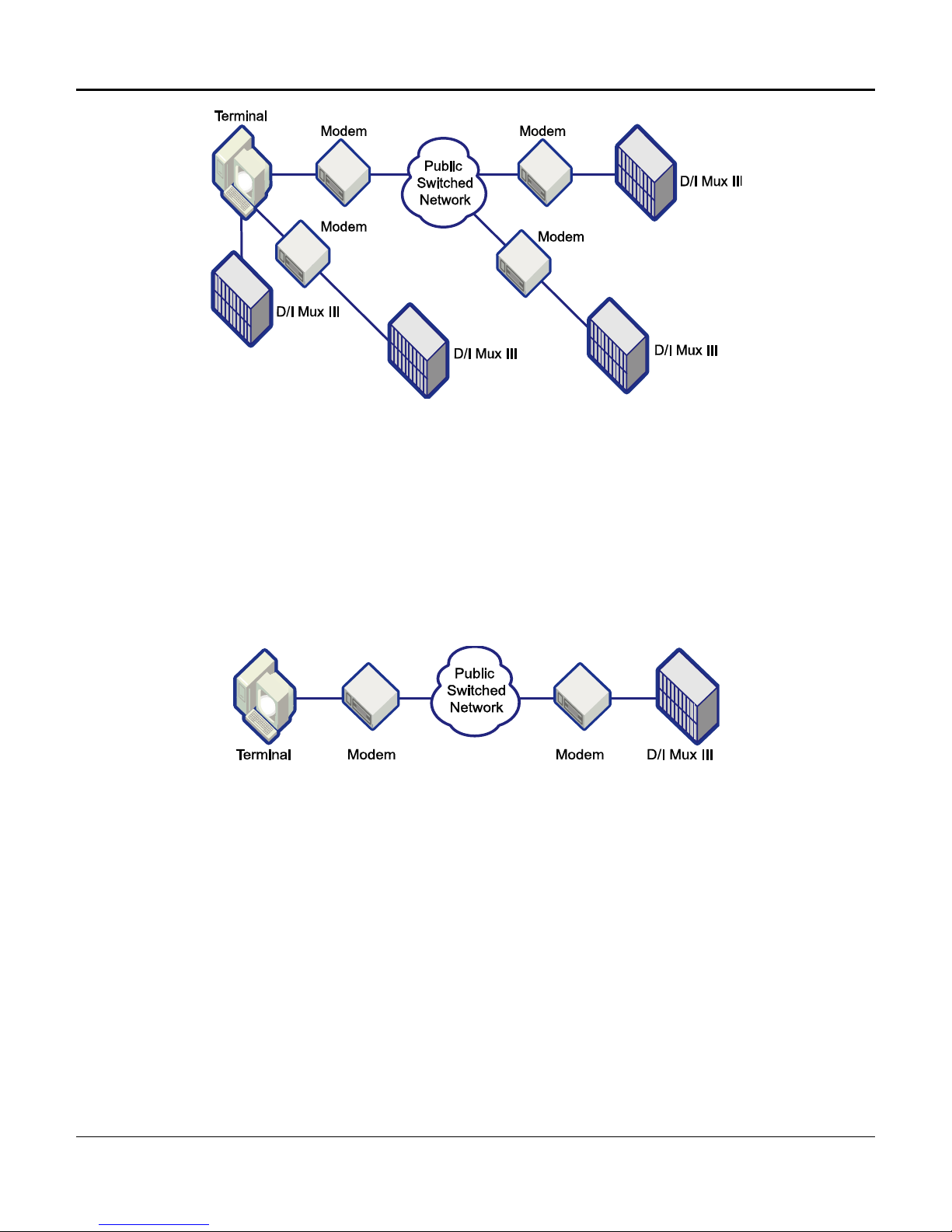
Remote Control with AMCU
Remote control of the D/I Mux III system is made possible through the use of a modem
connection to the D/I Mux III COM port (also referred to as the control port). A terminal and
modem are connected at the user site, and call up the remote system using terminal emulation
software. Figure 1-3 illustrates remote control through use of AMCU system software.
Figure 1-3. System Remote Control Via AMCU
SNMP
Advances in internetworking during the 1980s forced the definition of a new network management
standard, creating the Simple Network Management Protocol (SNMP), the most widely used market
standard to date. The optional Advanced Multiplexer Control Unit (AMCU) provides the SNMP option by
adding networking capability to an enhanced, modular version of the CCU card.
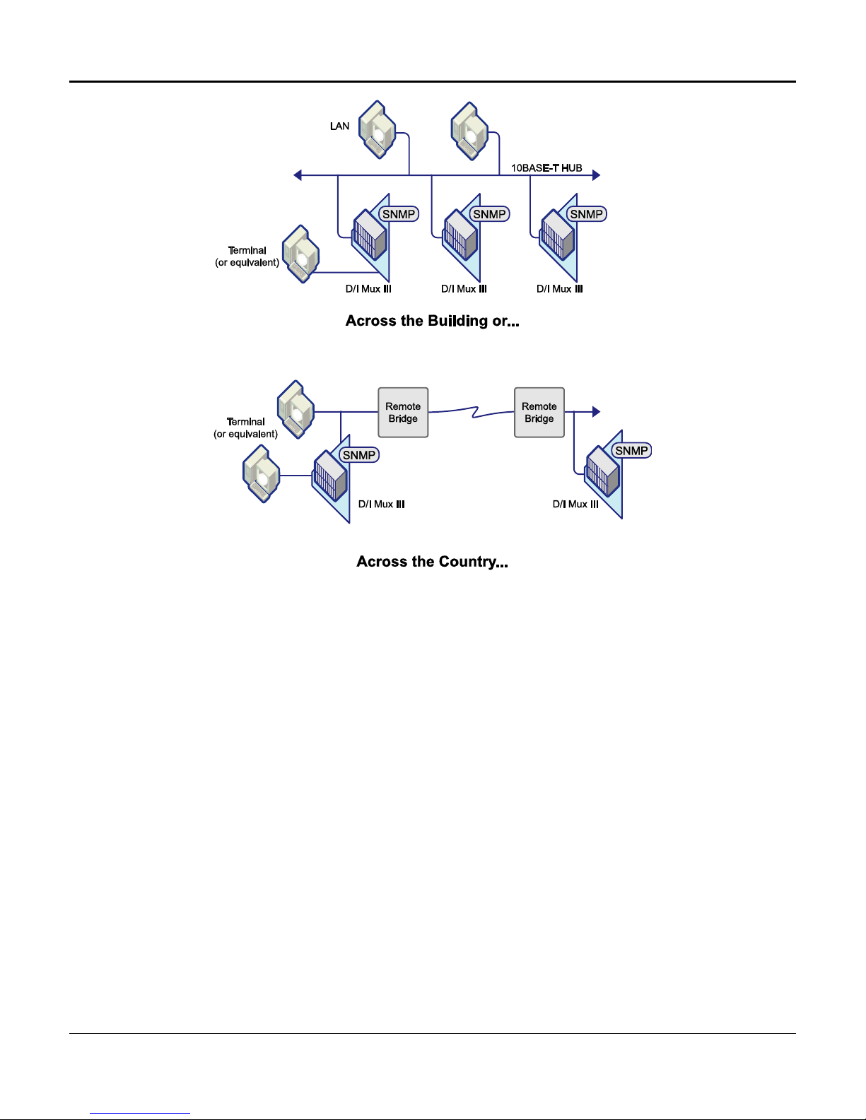
SNMP provides a set of features that allows management of T1 devices by more than one SNMP
manager from anywhere in an Ethernet 10Base-T Local Area Network (LAN), as depicted in Figure 1-4.
Coastcom’s SNMP products communicate with SNMP managers from vendors whose products comply
with Request for Comment (RFC) 1157.
4
Chapter 1. System Overview and Modes of Operation
Figure 1-4. SNMP Helps Manage Network Elements via LANs Close at Hand or Over Long Distances
While most of the connectivity and interoperability issues in networking have been resolved, it is still vital
that network devices be monitored, network performance checked, and that network problems be
remotely diagnosed and corrected. Network management achieves these goals, and SNMP is the most
widely accepted market standard for Transmission Control Protocol-Internet Protocol (TCP/IP)-based
environments.
Coastcom implements SNMP using a powerful AMCU that offers the following features:
• Native SNMP that eliminates the need for proxy hardware
• Support of Management Information Base 2 (MIB2) and DS1 MIB
• Intel i960 RISC processor-based AMCU speeds data processing
• Local serial interface allows programming of the unit through use of a dumb terminal, or via a PC with
terminal emulation
• An Ethernet 10Base-T port offering Telnet VT-100, or VT-220 terminal emulation over a LAN
• Downloadable code support via a Personal Computer Memory Card International Association
(PCMCIA ) card.
5
Chapter 1. System Overview and Modes of Operation
Serial Line Internet Protocol (SLIP)
A D/I Mux III with the SNMP option will usually be connected through a Local Area Network (LAN) to one
or more SNMP managers. The network connection can be made either through an Ethernet 10Base-T,
or serial port connection.
A direct Ethernet connection is preferred. This is accomplished by connecting the 10Base-T jack,
located on the AMCU front panel, to a hub or other suitable network device with an appropriate cable.
If a direct Ethernet connection is not feasible, the Serial Line Internet Protocol (SLIP) connection can be
used. A serial connection is accomplished by linking the SLIP/PPP jack on the AMCU front panel to a
router or other suitable network device by any means appropriate for a serial connection. The router
must be configured for a SLIP connection.
While a serial network connection is significantly slower than an Ethernet connection, it is more flexible.
The serial link can be carried by a D/I Mux Subrate Data Multiplexer (SDM) channel, or in any of a
number of other ways in addition to a direct cable connection.
While it is possible to use both the Ethernet and SLIP/PPP ports simultaneously, this is usually not done
because the AMCU card has no internal bridging or routing capabilities. Additionally, the SLIP feature
does not currently support the use of modems.
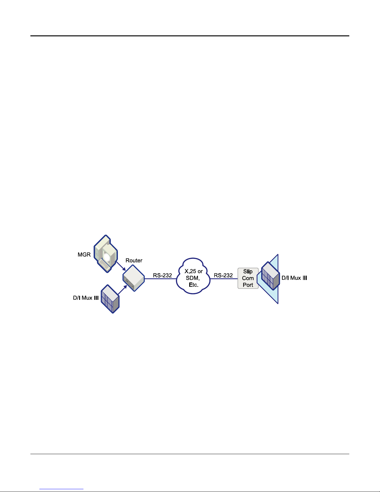
Figure 1-5 depicts SLIP operation with a network manager sending message traffic through a router, via
RS-232 cabling, and through an SDM or other transport medium, to the SLIP COM port of a far-end D/I
Mux.
Figure 1-5. Serial Line Internet Protocol (SLIP) Connection
6
Chapter 1. System Overview and Modes of Operation
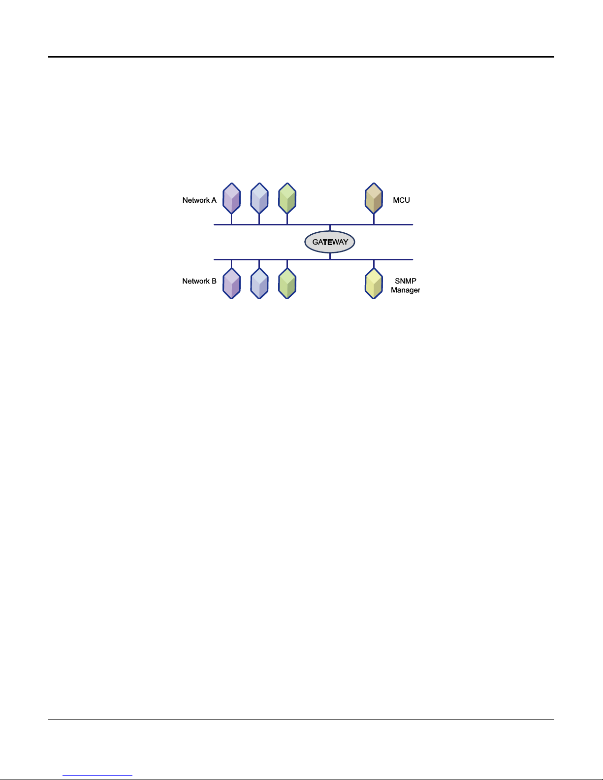
Gateway
The AMCU makes special provision for the case where it is connected to a network that is linked to other
networks by a Gateway (special router). In this case, messages to the manager must be addressed to
pass through the Gateway, and the address of the Gateway must be known to the AMCU. If the AMCU
is configured with a “default Gateway address,” messages to SNMP managers with IP Addresses not on
the same network as the AMCU will not be properly addressed and forwarded by the indicated Gateway.
Figure 1-6 depicts a typical Gateway connection across two networks with different IP Addresses.
Figure 1-6. Gateway Connection
Transmission Control
T1 equipment operates at 1.544 Mbps, which is the product of the twenty-four 64 Kbps channels, plus 8
Kbps for overhead. This is known as the DS-1 rate and a T1 facility is known as a DS-1 facility. The
common (inter-exchange) carriers (e.g., AT&T, MCI, SPRINT, etc.) divide the DS-1 signal into the 24 64Kbps DS0 channels, using this signal rate as a standard digital communications interconnection method
within North America. Local Exchange carriers, such as Pacific Bell and Southwest Bell, etc., also offer
this service for private networks.
The T1 signal is based upon what are known as DS1 Frame, and DS1 Extended Super Frame (ESF).
Simply defined, the DS 1 ESF scheme is as follows:
• DS0 Data Signal - Unframed, continuous bit stream, at a rate of 64 Kbps
• DS0 Octet - Eight consecutive bit portions comprising DS0 data signal
• DS1 Frame - Twenty-four DS0 octets, preceded by one framing bit
• DS1 ESF - Twenty-four consecutive DS1 frames
• DS1 Data Signal - Continuous stream of DS1 frames, at the standard DS1 data rate of 1.544 Mbps
The DS1 signal consists of 24 time slots, each of which transmits and/or receives one DS0 within the
multiplexer. Some external signals are capable of more or less than one DS0, in which case several
DS0s might be required for one type of signal, while in other cases several signals might occupy just one
DS0. This determination is based upon the application, and number of channel cards included in the
system. DS0 time slots are user-configurable. Installing a channel card does not automatically assign
its transmission path. Time slots and physical card slots are independent of one another, and the
transmission path must be mapped.
7

Chapter 1. System Overview and Modes of Operation
D/I Mux III line card circuits transmit and receive information over user-assigned (mapped) DS0 channels
as data or voice. The map assignments are user programmed and the information is recorded in a line
card map.
Transmission Channel Assignments
A line card circuit which is not assigned a DS0 (T1 transmission channel) can be configured for
operation, but will not perform its transmission function until a DS0 has been assigned. Transmission
direction is configured using software commands that specify the mode of operation, the port, and
applicable timing options. Typically, the T1-1 port is automatically “on”.
The signaling type for a DS0 channel, whether voice or data, is designated in the DS0 assignment map.
When a DS0 is mapped to an intelligent line card it will allocate the correct voice or data signaling type
automatically. A hardware-configured card, or empty card slot, signaling type must be entered manually
in the DS0 assignment map. DS0 designations are listed in the maps as data, voice, transmit (T),
receive (R), through or unused (X).
When DS0 information passes through the multiplexer without being processed, it is referred to as a
through DS0.
Unused DS0s are those not assigned to a line card circuit.
Maps
Mapping is the process of defining which of the line card circuits use which of the 24 DS0 transmission
time slots. Mapping is controlled by software stored in the Common Control Unit (CCU). Up to seven
maps can be stored, with the map currently operating called the working map.
A map change alters the circuit-to-time-slot assignments. By changing to a new working map, the
system is able to change time slot assignments without causing data errors on unchanged DS0s.
Maps are set to start in response to user-specified times, an event, an alarm, or a manual keyboard
command.
Time triggered maps reconfigure the multiplexer automatically at a specified time. Voice circuits can be
decreased, and high-speed data capacity can be increased for evening or weekend operation. This
allows data backups and file transfers to process more quickly when voice traffic is low.
Event triggered maps are switched on by an event, such as a disaster situation or a demand
requirement, to meet unscheduled network traffic rerouting. The event is triggered when a physical
contact at the back of the multiplexer is grounded.
Alarm triggered maps are switched on by one of three alarm conditions: Bit Error Rate (BER) Alarm, Red
Alarm, or Yellow Alarm.
Manual maps are switched on only when a keyboard command is entered. Use a manual map when
only one map is required for the network, or to reconfigure a map. The time, event, and alarm maps can
also be switched on manually for testing or special requirements.
The D/I Mux III has eight preconfigured maps of commonly used configurations for setup without a
terminal. See Appendix D. Preconfigured Maps, for details.
8

Chapter 1. System Overview and Modes of Operation
Timing and Clock Source
Transmit clocks for the T1-1 and T1-2 transmission ports are derived from the sources illustrated in
Table 1-1 below.
Table 1-1. Clock and Timing Source
Clock Source Timing Source
T1-1/T1-2 Recovered Loop
Internal T1 Local
External Local
T1-2 Local
Slot-2 Local
With loop timing, the D/I Mux III in channel bank operation is synchronized to the T1 network. Clocks
recovered from the T1 network are used to create the T1 transmit clocks.
In local timing, the clock source for the T1 outputs is derived from the D/I Mux III internal 1.544 MHz
(Stratum IV) oscillator. This oscillator can either run freely, or be synchronized to an external clock.
In the drop-and-insert or dual channel bank loop timing mode, the D/I Mux III recovers clock from T1-1,
and uses this to create the T1-2 transmit clock. The T1-2 recovered clock is used to create the T1-1
transmit clock.
Alarms and Monitoring
Alarm detection is provided for both the T1-1 and T1-2 transmission lines. Common Bell System alarms,
as follows, are supported:
• Local alarm
• Remote alarm
• Carrier Group Alarm (CGA)
Audible, visual, and minor alarm contacts are provided. The audible and visual contacts indicate major
alarms. A major alarm indicates a service-affecting problem that requires maintenance action. Visual
contacts indicate a minor alarm, which is not service-affecting. However, it does require maintenance
action.
Alarms are indicated by front panel Light Emitting Diodes (LEDs), and are reported by the closing of
alarm relay contacts. Alarms are reported to both the CCU and AMCU.
Loss of frame synchronization, or loss of the receive signal, activates a local alarm. If the condition
persists for 2.5 seconds, the local terminal sends a yellow alarm to the remote end. The direction of
yellow alarm transmission is user-configurable to either T1-1, T1-2, or both.
If a local alarm exists for a user-defined period, or if a remote alarm is received, a Carrier Group Alarm
(CGA) is generated to initiate trunk processing in the D/I Mux III. Trunk processing “busies out”
(removes) circuits in an orderly fashion.
9

Chapter 1. System Overview and Modes of Operation
There are many other alarms in the D/I Mux III system. Alarms are rated as major, minor, and
informational. Details of the various alarms are described in Chapter 5. Diagnostics.
Power Failure Alarm
All of the alarm contacts on the D/I Mux III are open during non-alarm conditions. Power failure,
or removing a power supply (or both supplies if redundant DC units are installed), will cause the
visual and audible alarm contacts to close.
Alarm LED Indicators, Alarm Cut-off, and Bypass
The D/I Mux III has Light Emitting Diode (LED) indicators for alarms, alarm cut-off, and bypass.
After an alarm has occurred, an alarm cut-off (ACO) button, or corresponding software selection,
allows the user to turn off the audible alarm relay. The bypass (BYP) button, or software bypass,
allows the D/I Mux III to be bypassed. The bypass button only activates when there is a major
alarm. Bypass is only possible in drop-and-insert or ALPS mode with a Dual Digital Signal CrossConnect (DSX-1) interface during a power failure. (A Dual DSX-1 Interface will cause the shelf to
go into bypass immediately if it loses power.) In redundant DC power systems, both power
supplies must fail at any given output before the system enters the bypass mode.
Power Supply Failure Indicator LEDs
The red failure indicator will turn on if any power supply-regulated voltage is out of tolerance, or if
fuses F1, F2, or F3 are blown on, or removed from the -48 V DC power supplies.
In redundant DC power systems, the system software indicates if one power supply has failed.
This allows insertion and removal of either power supply without interrupting service unless both
power supplies are being used to provide power to the channel cards.
Minor Alarm
The minor alarm relay closes for minor alarm reporting. These pins are accessible on the D/I Mux
III backplane, at the contacts labeled MNR. The minor alarm can be activated by the system
reporting a minor alarm, such as a Cyclic Redundancy Code (CRC) error, or redundant power
supply failure. (Refer to Chapter 5. Diagnostics for more information on alarms.)
Bypass
When the D/I Mux III is configured for drop-and-insert operation, bypass causes the T1-1 span to be
connected to the T1-2 span, bypassing the D/I Mux III so that “through T1” is uninterrupted.
The bypass operation can occur automatically, through software selection, or through manipulation of
front panel switches.
When a Dual Digital Signal Cross-Connect (DSX-1) Interface is installed in a D/I Mux III, bypass
automatically occurs when any of the common equipment is removed, or if an out-of-tolerance voltage is
supplied to the system (a brownout occurs). Dual Channel Service Unit (CSU) interfaces do not go into
bypass because protected DC power is used for their operation.
During an alarm condition, bypass can be selected using the bypass switch on the CCU, or AMCU, front
panel. Before bypass can be activated, the alarm condition must be acknowledged by selecting Alarm
Cut-off (ACO) via software, or at the front panel. Bypass can be software-selected at any time.
10

Chapter 1. System Overview and Modes of Operation
Trunk Processing
When a local alarm, remote alarm, or system failure causes a Carrier Group Alarm (CGA) to
occur, trunk processing removes line cards from service in the D/I Mux III. When the problem is
cleared, service is restored. Disabling CGA is optional on some line cards. Refer to the individual
user manuals for further description of CGA operation with specific line cards.
T1 Interfaces - CSUs
There are three versions of Dual Channel Service Unit (CSU) interfaces available: T1/DSX-1, T1/T1,
and DSX-1/DSX-1. Each CSU provides slightly different options and capabilities for equalizing output
across twisted-pair cable. This process is called line build-out (LBO). This is required to compensate
for the characteristics of the twisted-pair cable so that the correct signal level and shape is received at
the DSX-1.
With the T1/DSX-1 version, LBO is provided on the T1-1 (network) side, and an equalizing network is
provided on the DSX-1 (terminal) side. This version can be used, for example, between a T1-2 network
and a digital PBX.
The T1/T1 version provides line build-outs on both sides as well as on both T1-1 and T1-2 to interface to
T1 carriers. This version is used in drop-and-insert or dual channel bank applications.
The DSX-1/DSX-1 version provides DSX equalization on both sides. This version is for private networks
which require T1 test capabilities. DSX-1 interfaces work well with transmission equipment such as
microwave radios and fiber optic modems.
Lightning Protection
When installed as an option with a CSU interface unit, lightning protection circuitry is included with the T1
inputs and outputs. It protects against high-voltage surges and spikes on the T1 line only; it does not
provide protection on the line card side.
T1 Testing With the CSU
The Dual CSU interface option provides integrated Channel Service Unit functions for the D/I Mux III T11 and T1-2 transmission paths, along with limited test functions.
A Dual CSU interface installed in a D/I Mux III shelf operates in conjunction with the other common
control units to provide the integrated CSU features. The CSU features are provided for both T1-1 and
T1-2 transmission spans, and include the following:
• Test loopback, network loopback, and bypass
• Lightning protection
• T1 span line build-out equalization
• Keep-alive signal (channel bank mode loopback)
• Span power can be terminated, looped back, or sent through the shelf
• Jackfield, for ease of maintenance
11

Power Supplies
-48 Volt DC Power Supplies
Two DC power supplies can be used to provide redundancy. In a redundant system, both power
supplies share the work. If one fails, the other automatically assumes the full load. In such a
configuration, either power supply can be inserted or removed without interrupting service.
Some applications require two power supplies for normal operation, as with Subrate Data
Multiplexer (SDM) line cards. In such cases where more than 12 data line cards require the use
of both power supplies, redundant operation is not possible.
The power supplies are designed to withstand a reverse polarity input connection without
sustaining internal damage.
The -48 V DC power supplies provide the following:
· Power-on indicator · Alarm reference voltage regulator
· Power supply voltage monitor circuitry · Alarm detect fuse failure and power supply fail
The power supply has built-in over-voltage and under-voltage failure detection circuitry. It
monitors +5 V, -5 V, +12 V, and -12 V outputs, and will initiate an alarm if the voltages are
approximately 10 percent out of tolerance.
Chapter 1. System Overview and Modes of Operation
indicator circuitry
-24 Volt DC Power Supplies
-24 V DC power supplies are available for special applications. They provide the same features
as the -48 V DC supplies, and operate with the line cards shown in Appendix B. -24 Volt
Compatibility. The Dual CSU interface, with integrated CSU capability (part numbers 30318-101,
30318-102, and 30318-103), will not operate in -24 V DC powered systems.
110 Volt AC Power Supply
An AC power supply is available for customer premise applications where only standard 110 V
AC power is available. Coastcom currently offers an AC/DC self-contained single-slot power
supply that provides all of the voltages necessary to operate a D/I Mux III - except ringing voltage.
When configured with FXS feature cards, a modular Ringing Generator 30333-101 will also be
needed. Provides +/-12, +/-5, and -48. Can be used in 8, 12 and 24-slot shelves. Replaces a
30308-102A and the combination option of 30315-105A with 30338-103A. Cannot be used in
combination with any other power supply.
NOTE: Previous to August of 2005, Coastcom offered two AC power supplies:
• The 30315-105 110 Volt AC supply worked in conjunction with the 30338-103 -48 V DC
power supply. It occupied one power supply card slot, and converted AC power into -48 V
DC. The -48 V DC power supply used the -48 V DC supplied by the AC power supply and
converted it into the required voltages normally used by 12-slot shelves.
• The 30308-102 AC power supply occupied both power supply card slots in a D/I Mux III 8slot or 24-slot shelf, and was not available for 12-slot shelves. The 30308-102 supplied all
the voltages required by the D/I Mux III, and allowed software voltage checks.
12

Chapter 1. System Overview and Modes of Operation
D/I Mux III User Circuit Interfaces
D/I Mux III circuit interfaces include:
• High speed synchronous data
• 56 Kbps to 1.536 Mbps (n times 56 or 64 Kbps)
• V.35 interface, RS-422/449, or RS-232C interface
• Low speed data
• 1.2 Kbps to 19.2 Kbps
• asynchronous or synchronous
• Digital Dataphone System (DDS) subrate compatible
• DS0A format
• DS0B format
• RS-232C interface
• DDS Interfaces
• Office Channel Unit Data Ports (OCUDP)
• 56 Kbps
• Switched 56 Kbps
• All Rate (2.4, 4.8, 9.6, 56 Kbps)
• 2-Wire Voice
• Foreign Exchange Service (FXS)
• Foreign Exchange Office (FXO)
• Private Line Automatic Ringdown (PLAR)
• Tandem Access (TA)
• 800 Service
• Megacom
• 2-Way Megacom
• Direct Inward Dialing (DID)
• Dial Pulse Origination (DPO)
• Dial Pulse Termination (DPT)
• MXS, MXO (used with Northern Telecom Meridian PBX)
• Orderwire
13

• 4-Wire Voice
• E&M (Types I, II, III, & V)
• Pulse Link Repeater (PLR)
• Transmission Only (TO)
• Modem
• Deluxe card with 2713 Hz loopback tone
• SCG
• High fidelity audio
• 8 kHz Bandwidth
• 15 kHz Bandwidth
Circuit Features
Status information on circuits includes:
• Option status
Chapter 1. System Overview and Modes of Operation
• Card type
• Serial number
• Card revision
• Firmware revision
Data Circuit Features
• Polling (most circuits)
• Test loopbacks
• Reset
• T1-1/T1-2 (bi-directional) provisioning
Voice Circuit Features
• Transmission level adjust (Tx and Rx)
• Test loopbacks
• T1-1/T1-2 (bi-directional) provisioning
Refer to individual circuit card user manuals for further information on options offered.
14

Chapter 1. System Overview and Modes of Operation
COMPONENT OVERVIEW
The Coastcom D/I Mux III multiplexer incorporates a modular design that is cost effective in meeting
specific applications, and requiring purchase of only what is needed. Modular system components are
easily added or removed as network requirements change, also simplifying maintenance.
There are three main system components to a D/I Mux III multiplexer: the shelf, the common equipment
units, and the line cards. It takes all three of these elements to make a complete D/I Mux III.
The shelf is the housing for the modular common control units and line cards. The shelf has a
multilayered backplane with card edge connectors inside to receive the various modules. On the back of
the shelf (backplane) are wiring connections for voice circuits, data circuits, T1 circuits, power, and
synchronization.
Common equipment units are the essentials of every multiplexer. They control the system, perform the
multiplexing function, and interface to the T1 transmission lines. A D/I Mux III must have either a
Common Control Unit (CCU) or an Advanced Multiplexer Control Unit (AMCU), two Line Interface Units
(LIUs), a Dual DSX-1 or Dual CSU Interface, Strobe cards (upper and lower strobe cards for the 24-slot
shelf), and a power supply. These are the units common to every system, and they reside in specific
shelf card slots.
Line cards offer application-specific circuits to the user. They include voice, data, and special services.
Unless otherwise specified, a line card can be installed in any shelf line card slot. The circuits from the
line cards are multiplexed into the T1 transmission signal through the common equipment and shelf
backplane. Figure 1-7 depicts a simple D/I Mux III system in block diagram.
15

Chapter 1. System Overview and Modes of Operation
16

Chapter 1. System Overview and Modes of Operation
Shelves
Shelves house the common equipment and channel units. The shelf backplane supplies the bus
connectivity for provisioning the common equipment and channel units.
Coastcom D/I Mux III multiplexers include the following shelf types (see Figure 1-8).
• D/I Mux III, 8-slot with 8 line card slots and 2 T1 transmission ports
• D/I Mux III, 12-slot with 12 line card slots and 2 T1 transmission ports
• D/I Mux III, 24-slot with 24 line card slots and 2 T1 transmission ports
The number of slots (i.e., 8, 12, and 24) refers to the number of slots available for installation of line
cards after the common equipment has been installed. Common equipment, such as the CCU, AMCU,
and LIUs, do not occupy any of the 8, 12, or 24 slots.
The three shelves accommodate the same common equipment and line cards (except the 12-slot, which
will not accept the now obsolete 30308-102A AC/DC power supply, due to physical layout of the shelf).
All D/I Mux III shelves include an Electrostatic Discharge (ESD) strip located at the base of each card slot. The
ESD strip protects data transmission from errors caused by electrostatic discharge. The ESD strip is labeled, or
silk-screened, with the correct common equipment component name for that particular slot.
17

Chapter 1. System Overview and Modes of Operation
Figure 1-8. D/I Mux III 8-, 12- and 24-Slot Shelves
Shelf Backplane Connectors
A DB-9 female connector can be used as a synchronous input/output (Sync I/O) port to
synchronize the D/I Mux III with other systems. Both the synchronous output and the external
clock input are available on the DB-9 simultaneously. The Sync I/O provides an 8 kHz framealigned Transistor Transistor Logic (TTL) output clock. The external clock input can be either a
single ended (TTL), or differential (V.35/RS-422) signal.
A DB-25 male connector is used for the COM port, which connects the system control terminal to
the D/I Mux III with an RS-232C cable.
The DB-25 male COM2 connector is reserved for future use.
The DB-25 female COM1 connector is used to connect a serial printer for a permanent record of
T1 transmission performance. It is only operational when a Facility Data Link Processor (FDLP)
is installed, and a network Line Monitoring Unit requests performance per AT&T Publication
54016.
DB-15 female connectors, or RJ-48 connectors, are used to connect to the T1 transmission lines.
Both connectors are wired in parallel for convenient selection. The T1-1 connector is used for
channel bank mode. Both T1-1 and T1-2 connectors are used for drop-and-insert, dual channel
bank, and ALPS modes.
Line cards connect to the shelf backplane via a 50-pin male Amphenol-type connector. DB-25
female connectors connect each card to the network. Jumpers select whether each card slot
uses the DB-25 or 50-pin connectors. For data applications, the D/I Mux III end of the cable must
have a male DB-25 connector. The opposite end of the cable will have the appropriate connector
to match the user's equipment.
The DB-25 connector always has voice/data on it when a line card is installed, even if the 50-pin
connector is being used. The VF/Data jumper should be in the VF position when using the 50-pin
connector.
See Figures 3-8 through 3-11 for backplane illustrations.
18

Chapter 1. System Overview and Modes of Operation
Common Equipment Units and Line Cards
The common equipment units and line cards are separately packaged plug-in circuit boards that are
installed into the D/I Mux III shelf. The upper front edge of each unit is fitted with a captive screw that
secures it to the D/I Mux III shelf. Inputs and outputs are terminated in gold-plated contacts on the rear
edge of the circuit board. See Figure 1-9 for an illustration of a D/I Mux III channel card unit including
descriptive front panel.
Status
Figure 1-9. Typical D/I Mux III Channel Card
Common Equipment
The following section lists and describes the D/I Mux III system common equipment. The common
equipment functions are illustrated in simplified block diagrams.
Common Control Unit
The Common Control Unit (CCU) stores the operating parameters for control and monitoring of all common
equipment and channel cards in the D/I Mux III. The primary functions of the CCU are as follows.
• Provide an interface for an asynchronous terminal or network management system
• Control and monitor other common equipment and channel cards
• Manage all alarm functions
• Control T1 clock selection
• Control alarm cutoff (ACO) and bypass (BYP) functions
• Provide a date and time clock (“real time” clock)
• Provide nonvolatile storage of the shelf configuration
See Figure 1-10 for a detailed CCU motherboard circuit flow block diagram.
19

Chapter 1. System Overview and Modes of Operation
Figure 1-10. Common Control Unit Block Diagram
20

Chapter 1. System Overview and Modes of Operation
CCU Circuit Description
The following section lists and describes the various components comprising the Common
Control Unit (CCU).
Microcontroller
The microcontroller, running a real time multi-tasking operating system, controls all the
functions of the CCU, provides alarm integration, accepts user commands over either the
asynchronous terminal or network interface, and issues commands to other provisionable
units over the RS-485 provisioning bus.
RS-485 Provisioning Bus Interface
Communication between the common equipment and channel cards takes place over a
balanced serial bus at 19.2 Kbps. This polled multidrop system allows only one unit to
transmit over the bus at any time. All equipment may monitor and receive messages
simultaneously.
RS-232C Interface
The RS-232C electrical interface provides the communications to the system control
terminal. The serial interface supports the following standard asynchronous
communication data rates: 300, 1200, 2400, 4800, 9600, and 19,200 bps. The default
setting from the factory is 1200 bps.
ROM
The Read Only Memory (ROM) contains the instructions used by the microcontroller.
RAM
The microcontroller uses the Random Access Memory (RAM) for "scratch pad" memory.
Nonvolatile RAM
Onboard Nonvolatile Random Access Memory (NVRAM) provides nonvolatile storage of
map information and other critical data for configuring the system. All channel card
settings and parameters are also stored in NVRAM. A 7-year lithium battery included on
the card preserves the information stored in NVRAM when power to the card is removed.
Date and Time Clock
The date and time (real time) clock provides accurate time information (day, date, hour,
minute, second) used for shelf configuration and operation. The date and time clock is
also powered by the 7-year battery.
Alarm Relay Circuits
The alarm relay circuits operate the relay contacts that are normally open for the visual,
audible, and minor alarms.
Alarm Cut-Off and Bypass Switch Circuits
The Alarm Cut-Off (ACO) and Bypass (BYP) circuits can be activated from front panel
switches on the CCU, or through terminal control.
21

Chapter 1. System Overview and Modes of Operation
LEDs
Light Emitting Diode (LED) circuits activate the LEDs for the current status of alarms,
operation modes, and switches.
Clock Select
The clock select function provides independent T1 clock selection options for T1-1 and
T1-2 as follows. Only in a drop and insert or dual channel bank configuration is this valid.
• Recovered clock T1-1
• Recovered clock T1-2
• Internal Stratum IV (1.544 MHz) clock source
• External clock with the backplane DB-9 Sync I/O connector
• Slot 2 synchronization source
Frequency Synthesizer
The frequency synthesizer produces a 1.544-MHz Stratum IV clock. It can synchronize
an external clock input that is 8 kHz or greater, and a multiple of 1600 Hz up to 1.544
MHz. The external clock is from either the backplane Sync I/O or the Slot 2
Synchronization source; selection is under software control.
Advanced Multiplexer Control Unit (AMCU)
The Advanced Multiplexer Control Unit (AMCU) is a two-circuit board assembly, comprising the
control functions of the D/I Mux III system with the SNMP feature. It is incompatible with all
releases of NCC products, and does not support Coastcom proprietary Machine Machine
Language (MML). For information on downward compatibility with CCU releases, contact
Coastcom’s Application Engineering Department.
The AMCU is comprised of a motherboard and a sub-board, offering the following features.
• Software download capability in FLASH ROM via a PCMCIA-compatible FLASH memory
module
• Support of all current line cards via the provisioning bus physical interface and protocol
• Current D/I Mux III control by dumb terminal, and PC terminal programs
• Ethernet 10Base-T port for SNMP manager and Telnet terminal emulation over a LAN
AMCU Motherboard Circuit Description
The following section lists and describes the various components of the AMCU module.
Microcontroller
The microcontroller, running a real time multi-tasking operating system, controls all the
functions of the AMCU, provides alarm integration, processes user commands, and issues
commands to other provisionable smart units over the RS-485 provisioning bus.
22

Chapter 1. System Overview and Modes of Operation
RS-485 Provisioning Bus Interface
Communication between the common equipment and line cards takes place over a
balanced serial bus at a data rate of 19.2 Kbps. This polled multidrop system allows only
one unit to transmit over the bus at any given time. All equipment can monitor and
receive messages simultaneously.
UART
The Universal Asynchronous Receiver/Transmitter (UART) device interfaces the
motherboard to the sub-board.
FLASH ROM
The FLASH Read Only Memory (ROM) contains the operating instructions used by the
microcontroller.
RAM
The Random Access Memory (RAM) is used by the microcontroller for “scratch pad”
memory.
Nonvolatile RAM (NVRAM)
Onboard Nonvolatile Random Access Memory (NVRAM) provides nonvolatile storage of
map information and other critical data for configuring the system. All channel card
settings and parameters are also stored in NVRAM. A 7-year lithium battery included on
the card preserves the information stored in NVRAM when power to the card is removed.
Date and Time Clock
The date and time (real time) clock provides accurate time information (day, date, hour,
minute, second) used for shelf configuration and operation. The date and time clock is
also powered by the 7-year battery.
Alarm Relay Circuits
The alarm relay circuits control and operate the relay contacts that are normally open for
the visual, audible, and minor alarms.
Alarm Cut-Off and Bypass Switch Circuits
The Alarm Cut-Off (ACO) and Bypass (BYP) circuits can be activated from front panel
switches on the MCU, or through terminal control.
LEDs
Front panel Light Emitting Diodes (LEDs) display alarm status, ACO status, and bypass
status.
23

Chapter 1. System Overview and Modes of Operation
Clock Select
The clock select function provides T1 clock selection options for T1-1 and T1-2 as follows:
• Recovered clock T1-1
• Recovered clock T1-2
• Internal Stratum IV (1.544 MHz) clock source
• External clock with the backplane DB-9 Sync I/O connector
• Slot 2 Synchronization source
Clock should only be present on
either/or, not both , unless sourced form
}
the same reference.
Frequency Synthesizer
The frequency synthesizer produces a 1.544 MHz Stratum IV clock. It can synchronize an
external clock input that is 8 kHz or greater, and a multiple of 1600 Hz up to 1.544 MHz.
The external clock is from either the backplane Sync I/O, or the Slot 2 Synchronization
source; selection is under software control.
See Figure 1-11 for a detailed AMCU motherboard circuit flow block diagram.
24

Chapter 1. System Overview and Modes of Operation
Figure 1-11. AMCU Motherboard Circuit Flow Block Diagram
25

Chapter 1. System Overview and Modes of Operation
AMCU Sub-Board Circuit Description
The AMCU sub-board interfaces to the AMCU motherboard via a 20-pin connector, and includes
the hardware that supports SNMP. A full TCP/IP communication protocol stack allows SNMP
and Telnet to communicate with a centrally located Network Operations Center (NOC). A
network manager uses automated tools (for example, to read or compile a Management
Information Base, or MIB) to manage distributed node devices, including D/I Mux III multiplexers.
See Figure 1-12 for a detailed AMCU sub-board block diagram.
Figure 1-12. AMCU Sub-board Circuit Flow Block Diagram
The following section lists and describes the various elements and components comprising the
AMCU sub-board circuit.
26

Chapter 1. System Overview and Modes of Operation
Microprocessor
The 32-bit Reduced Instruction Set Computer (RISC) microprocessor controls all functions
on the AMCU sub-board. The microprocessor executes the protocol stack, and handles
communication with the Ethernet 10Base-T and serial interfaces.
Flash EPROM
The FLASH EPROM is 1 M x 16.
DRAM
The DRAM is 1 M x 16.
EEPROM
The EEPROM is 256 x 16. It provides nonvolatile storage of AMCU card information,
such as card type, card serial number, Media Access Control (MAC) address, and
hardware revision and date. EEPROM data is entered during the factory test procedure,
and is read only during normal AMCU operation.
LEDs
The front panel of the AMCU has four Light Emitting Diode (LED) indicators. Two of the
LEDs glow green. One, marked ACO, indicates alarm cutoff, while the other green LED,
marked BYP, indicates that the multiplexer is being bypassed.
Another LED glows red to indicate a major alarm condition impacting service. It is marked
MAJ (major). The LED marked MIN (minor), which glows yellow, indicates faults
occurring that do not impact service. For more information on LEDs, see Chapter 3.
Installation, and Chapter 5. Diagnostics.
I/O Ports
The AMCU utilizes the standard CCU provisioning bus port and a COM port for “normal”
operation. The provisioning bus is an RS-485 half-duplex asynchronous port, while the
COM port is a full-duplex asynchronous RS-232C port with user-selectable data rates.
(Refer to Chapter 3. Installation, for details.)
An Ethernet 10Base-T port allows terminal emulation over a LAN for SNMP and Telnet
network management.
Code Download
Code download by the AMCU can be initiated in one of three ways:
1. Automatically on system start-up
2. External indication (pressing the ACO and BYP buttons at system power-up, and
holding for one minute)
3. Software menu selection
Code download occurs at system start-up after the AMCU computes the checksum of its
stored code. If a bad checksum is detected, the AMCU requests a code download from
the sub-board.
27

Chapter 1. System Overview and Modes of Operation
Code download occurs by external indication when a PCMCIA card is inserted, and an
NVRAM power-up is initiated by pressing the ACO and BYP buttons for one minute, at
system power-up. During the power-up, the AMCU will compare its software revision with
that on the PCMCIA card and, if different, it will download the code to the AMCU. For
information about code download through menu selection, see Chapter 4. Configuration
and Operation.
AMCU Power Consumption
The AMCU consumes more power on the +5 V line than does the CCU, due chiefly to the
RISC processor, peripheral Integrated Circuits (ICs), and the Ethernet 10Base-T port.
28

Chapter 1. System Overview and Modes of Operation
AMCU User Interfaces
The AMCU may be accessed in three ways:
• An SNMP manager, such as Hewlett Packard’s OpenView
© -
An SNMP manager
accesses all Management Information Base II (MIB-II) parameters supported by the
SNMP agent, and all the DS1 MIB values supported by the current D/I Mux III
software. (See MIB-II and DS1 MIB in Appendix H.) Special configuration screens
allow the user to branch to either the LAN, and login parameters, or to the standard
screens supported by the CCU.
• A local terminal (all values available by local terminal will also be available via the
Telnet connection except IP address and subnet mask) - The local terminal is an RS-
232 serial connection. The user must use the local terminal to enter an initial IP
Address and subnet mask. Using the local terminal will also lock out a Telnet
session. However, a keyboard idle timer can disconnect the serial connection and
allow a Telnet session.
• A Telnet session - A Telnet session can be connected over Ethernet 10Base-T as a
virtual terminal (VT) connection, normally providing VT-100, or VT-220 functionality.
A Telnet client is required by the user to make this connection and, once connected,
the Telnet screen presentation is that of a serial connection.
29

Chapter 1. System Overview and Modes of Operation
Strobe Units
The Strobe Units activate the line card transmission paths (for transmit and receive) on the T1
digital bus by sending strobe signals corresponding to DS0 timeslots, to the line cards. The
strobed line cards then read and/or write to the T1 digital bus during the strobed period.
DS0 time slots and physical card slots are independent of each other; further, installing a line
card does not assign its transmission path within the D/I Mux III system. Mapping controls strobe
assignments, and the transmission path must be mapped. For more information on mapping,
refer to Chapter 4. Configuration and Operation.
Strobe signals are assigned and placed in software-configurable maps in both the CCU and
AMCU. The signals are downloaded to the Strobe units during system initialization and map
programming. Informational changes to a map are sent to the Strobe unit from the CCU. These
changes can include altering connections from line cards to time slots, or switching to another
configuration map. By changing to a new working map, the Strobe unit is able to change DS0
assignments without causing data errors on unaffected DS0s. The maps can be set to start in
response to a user-specified time, event, or keyboard entry.
High-speed Dual Synchronous Data Channel Unit (DSDCU), Digital Program Channel cards
(DPCs), and the Tandem Access Unit (TAU) can require more than one strobe, and can move a
greater amount of data on one circuit.
The Upper Strobe unit (P/N 30307-101 or 30307-103) is functionally equivalent to the Lower
Strobe unit (P/N 30307-102 or 30307-104A). The Upper Strobe is used only for the D/I Mux III
24-slot shelf, and provides transmission control for the line cards in the top half of the shelf. The
Lower Strobe unit provides transmission control for the line cards in the bottom half of a 24-slot
shelf, and for 8-slot and 12-slot shelves.
Strobes perform the following functions:
• Provide transmission control of the line cards
• Store map configuration data when power is on (the CCU and AMCU store maps during
power-off)
• Change maps as required by event, time, or demand
Map Select Option Switches
DIP switches on the Lower Strobe unit can be used to manually select a preconfigured
map. Eight different maps are available to load into one map location (e.g., map number
1) after power-up and initialization (see Appendix D. Preconfigured Maps.) The switches
on the Upper Strobe unit do not affect map selection.
Initialization
On power-up, the Strobe units perform a diagnostic check of program memory, operating
Random Access Memory (RAM), and dual-port map RAM. The Strobe units also receive
map configuration data from the CCU and AMCU.
Figure 1-13, following, is an illustration of a strobe unit block diagram.
30

Chapter 1. System Overview and Modes of Operation
31

Chapter 1. System Overview and Modes of Operation
Line Interface Units
Line Interface Units (LIUs) perform the primary multiplexing functions in the D/I Mux III system.
Information from the various line cards is combined and converted to T1 format, and information
from the network is distributed to the line cards, through the LIUs. Circuitry to option various
framing and coding takes place in the LIUs. LIUs also recover and supply T1 clock and framing.
The D/I Mux III system, whose architecture was designed primarily for drop-and-insert operation,
requires the use of two LIUs in every mode of operation. Channel bank mode, where only one T1
is accessed, also requires a pair of LIUs. The two LIUs are slightly different and must be installed
in their designated card slot.
There are three paired versions of LIUs available for the D/I Mux III, depending upon
configuration. They include the standard LIUs for use with twisted-pair cable, the ALPS LIUs,
and the Fiber LIU module for use with fiber optics.
For channel bank, drop-and-insert, or dual channel bank operation, use:
• Line Interface Unit B (T1-1) - Part Number 30309-104A
• Line Interface Unit A (T1-2) - Part Number 30309-114A
For channel bank, drop-and-insert, dual channel bank, with ALPS operation, use:
• ALPS Line Interface Unit B (LIU-B) - Part Number 30309-105
• ALPS Line Interface Unit A (LIU-A) - Part Number 30309-115
Note: ALPS LIUs are not discussed in this manual. Refer to the ALPS User's Manual
for information on the ALPS LIUs.
LIU Functions
The primary functions of the LIUs are as follows.
• Recover clock
• Attenuate jitter
• Detect framing and adjust multi-frame alignment
• Drop data to channel units and insert data into T1 line
• Generate outgoing Alternate Mark Inversion (AMI)
• Provide LEDs for status information
• Provide provisioning ability
• DS0 blocking (30309-105 and 30309-115 LIUs only)
• Provide T1 loop code generation
• Receive loop code from T1; notify CSU interface to loop up
See Figure 1-14 for a detailed LIU block diagram.
32

Chapter 1. System Overview and Modes of Operation
Figure 1-14. Line Interface Unit Block Diagram
LIU Network Loop Switch
The LIU Network Loop switch sends a standard loopback code to another D/I Mux III or
Channel Service Unit (CSU) at the remote end. After a network loop is established, the
information sent to the remote end will return to the local D/I Mux III as a loopback. The
LIU Network Loop only functions when a Dual CSU Interface is installed.
33

Chapter 1. System Overview and Modes of Operation
T1 Interface Units
Coastcom offers five interfaces to the T1 transmission lines for various types of applications.
There are three versions of the Dual Channel Service Unit (CSU) Interface (with integral CSU
functionality), and two versions of the Dual Digital Service Cross-Connect DSX-1 Interface (with
no CSU functionality).
Dual CSU Interface
The Dual CSU interface offers dual DS1 interfaces for D/I Mux III. The Dual CSU
interface provides either a Channel Service Unit (CSU) interface or a DSX-1 interface
between the T1 line and the equipment. A Dual CSU interface provides test, network, and
loop/bypass functions for both the T1-1 and T1-2 directions.
The Dual CSU interface is available in three models:
• Dual CSU interface (T1/DSX-1) (P/N 30318-101) with a CSU interface on T1-1 and a
DSX-1 interface on T1-2
• Dual CSU interface (DSX-1/DSX-1) (P/N 30318-102) with two DSX-1 interfaces
• Dual CSU interface (T1/T1) (P/N 30318-103) with two CSU interfaces
Dual CSU interfaces have a front panel power-on LED as well as access and monitor
jacks for line and equipment testing. The bantam jacks provide access for monitoring the
transmit and receive T1 lines. Access jacks allow for breaking and testing the signal.
Monitor jacks do not interrupt the signal. Dual CSU interfaces include line build-out
options at 0, -7.5, and -15 dB.
Note: The monitor jacks do not directly monitor the T1 lines. The T1 signal first passes
through a lightning protector and a repeater chip. If true T1 measurements are
required, use either a DB-15, or RJ-48, connector not already used for that circuit,
located on the back of the shelf. See Figures 3-12 & 3-13 page 3-20 for pinout
information.
Should any common equipment fail, Dual CSU Interfaces enter the bypass mode and the
shelf is looped on itself as a self-check.
In channel bank mode, the shelf outputs an Alarm Indication Signal (AIS) to the network.
If power fails in drop-and-insert mode, the T1 signal bypasses the shelf using the
equalization and repeater networks as long as -48 V DC is still applied to the shelf, or is
available from the internal AC power supply.
Dual DSX-1 Interfaces
The Dual DSX-1 Interfaces provide three main functions:
• Line equalization (optional)
• Equipment and monitor jacks for testing (optional)
• Shelf bypass contacts
34

Chapter 1. System Overview and Modes of Operation
The Dual Enhanced DSX-1 Interface (Model 30118-102) provides switch-selectable
output equalization for connecting the system to different lengths of twisted-pair cable.
This is required to compensate for the characteristics of the twisted-pair cable so that the
required signal level and shape is present at the DSX-1 cross-connect. Equalization for
cable lengths of 0 to 150 feet, 150 to 450 feet, and 450 to 750 feet is switch-selectable.
Bantam jacks are provided to access and monitor both the T1-1 and T1-2 lines (east and
west). Access jacks break-and-test the signal. Monitor jacks do not interrupt the signal.
The Dual Basic DSX-1 Interface, Model 30118-101, provides standard DSX-1 (150 feet)
equalization, and has no access or monitor jacks.
In the event of failure of any common equipment, Dual DSX-1 Interfaces enter bypass
mode, and the Pulse Code Modulation (PCM) generated by the LIUs is looped back on
itself in a self test. In channel bank mode, the shelf outputs an Alarm Indication Signal
(AIS, an unframed all-ones T1 signal) to the network. If power fails in drop-and-insert
mode, the T1 signal bypasses the shelf using only the equalization networks.
Power Supplies
Coastcom currently offers two (2) different power supplies for use with the D/I Mux III.
-48 VDC Redundant (P/N 30338-902)
The 30338-902 is a DC-to-DC converter used to power D/I Mux equipment from an external -48
VDC input supply. Generates +/-12 and +/-5 volt outputs as well as failure alarm signals. Also
provides primary (-48v) power fusing. Can be used in a redundant or load sharing configuration
when two power supplies are installed. When configured with FXS cards order modular Ring
Generator 30333-101. Can be used in 8/12/24 slot chassis. Replaces 30338-102.
120 VAC Power Supply (P/N 30315-505)
An AC/DC self-contained single-slot power supply that provides all of the voltages necessary to
operate a D/I Mux III - except ringing voltage. When configured with FXS feature cards, order
modular Ringing Generator 30333-101. Provides +/-12, +/-5, and -48. Can be used in 8/12/24
slot chassis. Replaces a 30308-102A and the combination option of 30315-105A with 30338103A. Cannot be used in combination with any other power supply.
Line Cards
Line cards provide an interface between user equipment and the D/I Mux III. The three types of line
cards offered by Coastcom include data cards, voice cards, and digital program cards.
Data Line Cards
Data line cards interface various Data Terminal Equipment (DTE) directly with D/I Mux III
multiplexers, without the use of modems for full-duplex transmission over T1 lines.
Software-programmable data line cards support synchronous data rates of 1.2 Kbps to 1.536
Mbps, and asynchronous data rates from 1.2 to 19.2 Kbps.
35

Chapter 1. System Overview and Modes of Operation
The Dual Synchronous Data Channel Unit (DSDCU) is ideal for computer- aided design (CAD),
computer-aided manufacturing (CAM), and high speed batch data applications. This protocoltransparent card also finds applications in multi-site polled or packetized LAN environments, and
videoconferencing. The DSDCU card incorporates proprietary local and remote loopback, plus
diagnostic and control capability.
The All Rate Office Channel Unit Data Port (OCUDP) supports both standard and Switched 56
Kbps Digital Data System (DDS) applications. It provides an interface between the DDS 4-wire
Alternate Mark Inversion (AMI) loop signal and D/I Mux III common equipment.
The Subrate Data Multiplexer (SDM) line card offers low speed synchronous and asynchronous
transmission. SDM channel units offer DDS-compatible operation and proprietary operation.
The premium SDM (pSDM) line card offers multipoint polling operation.
Voice Line Cards
D/I Mux III voice line cards provide the interface between the Pulse Code Modulation (PCM)
timeslot and the baseband voice and data signals.
Both hardware-configured and dual channel software-controlled 2-Wire FXS & FXO and 4-Wire
E&M, E&M/PLR; TO 4W with/SCG; MXS, MXO (for use with Northern Telecom Meridian PBX)
voice line cards and Orderwire cards are available for D/I Mux III multiplexers. .
Digital Program Line Cards
Digital program line cards provide an easily installed, economical radio program transmission
service over existing T1 carrier facilities. The transmit line card and the receive line card are both
required to make a complete circuit.
Transmit digital program line cards are used to transmit monaural or stereo audio programs over
T1 carrier facilities. The receive digital program line card provides studio-to-transmitter channel
lines over the T1 carrier facilities. The programming of the transmission path and allocation of
timeslots are user-programmable features.
The D/I Mux III offers the following digital program capabilities:
Transmits and receives monaural or stereo audio program over T1 carrier facilities
• 8 kHz or 15 kHz bandwidth
• Optionally equalizes frequency characteristics of various cable lengths
36

Chapter 1. System Overview and Modes of Operation
MODES OF OPERATION
There are four modes of operation available with a D/I Mux III system. The three main modes of
operation are single channel bank, drop-and-insert, and dual channel bank. These modes relate to the
setup, timing, and structure of the T1 network. The fourth mode, Automatic Loop Protection Switching
(ALPS), is described in Coastcom’s ALPS User's Manual.
Channel Bank Operation
In channel bank mode, a D/I Mux III terminates a single T1 transmission line on its T1-1 port, as depicted
in Figure 1-17. The D/I Mux III can synchronize with the T1 network (loop timing mode), or supply timing
to the T1 network (local timing mode).
Figure 1-15. Channel Bank Operation
Loop Timing
System loop timing is provided by the clock recovered from the incoming T1-1 signal. If the
incoming T1 reference clock fails, timing is derived from the D/I Mux III's local timing source.
Local Timing
Local timing clock source for the T1-1 output is derived from the system's internal 1.544 MHz
oscillator. This oscillator can run freely, or be synchronized to one of three different clock
sources as follows.
• DB-9 Clock - The DB-9 clock is an 8 Kbps to 1.544 Mbps external clock (provided by another
system), brought into the Sync I/O connector on the back of the D/I Mux III shelf. The DB-9
clock is either a V.35/RS-422 differential Signal, or a Transistor Transistor Logic (TTL) signal.
• Slot 2 Synchronization Clock - The Slot 2 Sync clock is an 8 Kbps to 1.544 Mbps clock
recovered from a line card in slot 2 of the D/I Mux III shelf.
• Recovered T1-2 (Rcvd T1-2) Clock - The Rcvd T1-2 clock is the clock recovered from a T1
input signal connected to the T1-2 port.
37

Chapter 1. System Overview and Modes of Operation
Drop-and-Insert Operation
In drop-and-insert operation a D/I Mux III connects two T1 transmission lines in a unique fashion, as
depicted in Figure 1-18. The D/I Mux III takes clock and DS0 channels from one T1 transmission port
and passes them through the system to the other T1 transmission port. Channels can be pulled from
(dropped), or placed on (inserted) the T1 line in either direction. The D/I Mux III line card circuits access
any of the 24 time slots in the DS1 signal. In drop-and-insert mode the system is always synchronized to
the network except during an alarm condition.
Any channels not accessed by the D/I Mux III in drop-and-insert mode are passed through digitally. This
unique multiplexing scheme introduces less than 20 ms of delay into the T1 line at each drop-and-insert
point.
In the event of a power outage in drop-and-insert operation, the T1 line bypasses the D/I Mux III
automatically, with a Dual DSX-1 interface installed. The Dual CSU interface requires -48 V DC to
operate.
Figure 1-16. Drop-and-Insert Operation
Recovered Timing
T1 basic timing is independent for each transmission direction in drop-and-insert mode, and is not
selectable. In this mode, both T1-1 and T1-2 clocks must be the same. T1-1 transmission timing
is provided by clock recovered from T1-2, and T1-2 transmission timing is provided by clock
recovered from T1-1. If one of the recovered clocks fails, the system can derive timing from the
internal clock or from the other T1 input. The choice of back-up clocks is software selectable.
Clock should not be present on both T1-1 and T1-2.
Dual Channel Bank Operation
In Dual Channel Bank (DCB) operation, a D/I Mux III terminates two T1 transmission lines. DCB mode
allows the system to synchronize with the T1 network (loop timing mode), or supply timing to the T1
network (local timing mode), as depicted in Figure 1-19.
DCB operation requires Line Interface Units (LIUs) (P/N 30309-104A and 30309-114A), which contain
“slip buffers.” In DCB mode the “slip buffer” LIUs align all clocks, bytes, frames and multiframes to one
common multiframe. T1 inputs and outputs are therefore synchronized to the same multiframe signal.
The “slip buffer” LIUs permit the T1 trunks of a D/I Mux III to operate in loop timing mode, recovering
clock from the network, or to be the source of network timing.
38

Chapter 1. System Overview and Modes of Operation
Figure 1-17. Dual Channel Bank Operation
Loop Timing
System loop timing is provided by clock recovered from the incoming T1 signals. If the incoming
T1 reference clock fails, then timing is derived from the internal timing source. This works like
drop-and-insert mode in which the T1-1 Receive clock sources the T1-2 Transmit clock, and the
T1-2 Receive clock sources the T1-1 Transmit clock.
The three loop timing clock sources used to set up the backup clock status include the following.
• T1-1 receiver
• T1-2 receiver
• T1-1 and T1-2 receivers
The T1-1 receiver and T1-2 receiver selections determine which span “faces” toward the clock
source. The “downstream” location (i.e., away from the clock source) must be set to recovered
timing.
The T1-1 and T1-2 receivers selection compensates for clock frequency variations between two
similarly timed T1 paths, as may be found between two different carriers. Note that while this
may imply that there are two clock sources here there are not
clock source per multiplexer.
. The D/I Mux III can only have one
Local Timing
Local timing clock source for the T1 outputs is derived from the system's internal 1.544 MHz
oscillator. This oscillator can run freely or be synchronized to one of two different clock sources
as follows:
• DB-9 Clock - The DB-9 Clock is an 8 Kbps to 1.544 Mbps TTL or V.35 external clock brought
into the SYNC I/O connector on the back of the D/I Mux III system shelf.
• Slot 2 Synchronization - The Slot 2 Sync is an 8 Kbps to 1.544 Mbps clock recovered from a
data line card in slot 2 of the D/I Mux III shelf.
39

Chapter 2. Applications
Chapter 2. APPLICATIONS
The D/I Mux III is a feature-rich product that can be configured to meet specific communications
requirements. Since the diversity of T1 networks and the circuits they transport is vast, users continue to
find new and innovative ways to use the D/I Mux III.
Several major applications and their modes of operation are described in this manual. These examples
can be used to gain an understanding of various network topologies.
Channel Bank
Channel bank operation is used to connect directly to the public network, or to create a point-to-point
private network.
Point-to-Public Network
In a point-to-public network a D/I Mux III is connected directly to the public network, as
depicted in Figure 2-1. In this configuration, the D/I Mux III connects T1 to the public digital
switching system.
Network-compatible circuits are a requirement, and include all of Coastcom's standard voice
frequency interfaces and Digital Dataphone Service (DDS) data cards. Each circuit is given a
telephone number or circuit identifier. Calls are routed and set up by the public digital
switching network. Calls and connections are initiated at the D/I Mux III, or at any location in
the network with a compatible type circuit.
Figure 2-1. Point-to-Public Network
Telephone Services
Standard telephone services are available for use with channel bank operation. The D/I Mux
III can connect directly to telephones, key systems, and Private Branch Exchanges (PBXs). It
can also connect to 800, Megacom, Direct Inward Dialing (DID) services, and direct outbound
dialing (DOD).
40

Chapter 2. Applications
Dual 2-Wire Foreign Exchange Subscriber (FXS) line cards connect directly to telephones
to supply standard telephone service. The circuits are assigned numbers at the digital
switch and standard telephones call out or receive calls.
The FXS card can also be used to access the available 800 and Megacom services. A
user with heavy customer service 800 lines has an economical and direct access to the
public networks 800 service switch.
Digital Dataphone Systems (DDS) Compatible Data
Data that is compatible with the DDS standard is distributed by the public digital switching
network. Most DDS data connections are point-to-point connections between two circuits.
The equipment at the far end does not have to be Coastcom equipment. Any equipment
that supports a compatible data rate and DDS type can communicate with Coastcom
equipment.
Office Channel Unit Data Port (OCUDP) line cards support 2.4, 4.8, 9.6, 19.2, 56 and 64
Kbps data rates, and are DS0A DDS type circuits. The public digital switching network
can take data from several OCUDPs, and distribute the data to divergent locations.
The OCUDP also includes an option for Switched 56 operation. In the Switched 56 mode
the data is directed to various locations by the user. A keypad on a Switched 56 Channel
Service Unit/Digital Service Unit (CSU/DSU) (ancillary equipment) can then call up other
Switched 56 locations similar to a standard telephone.
Coastcom's 5-port Subrate Data Multiplexer (SDM) line card offers DS0B DDS data rates
of 2.4, 4.8, 9.6, and 19.2 Kbps. The circuits are set up in a point-to-point configuration
with devices of the same data rate and DDS type. The DS0B DDS format makes efficient
use of bandwidth by placing up to five data circuits onto a single 64 Kbps DS0
transmission channel. In the Proprietary mode, the DS0B can support synchronous and
asynchronous transmission.
Coastcom's single-port SDM line card offers DS0A DDS type data at rates of 2.4, 4.8, and
9.6 Kbps. A single DS0A data circuit takes up all of a 64 Kbps DS0 transmission channel.
Point-to-Point Private Network
In a point-to-point private network, two D/I Mux III systems communicate only with each other, as
depicted in Figure 2-2. The T1 link between the two D/I Mux III systems is dedicated. The link
can be a variety of transmission types, including, microwave, fiber optic, or a leased line.
Communications carriers offer dedicated T1 links so a corporate network can remain private even
though it is being transported by several organizations.
41

Figure 2-2. Point-to-Point Private Network
4-Wire Trunks
Chapter 2. Applications
Private Branch Exchanges (PBXs) distribute calls from a local telephone central office.
PBXs are an economical way to minimize the connections, and cost, of doing business
with the local telephone company. The connections to the telephone company are
trunked (shared). Historically, the common connection between PBXs and local central
offices has been 4-Wire Earth and Magnet (E&M) trunks.
Coastcom offers 4-Wire E&M line cards for connection of PBXs within a private T1
network. Corporations that conduct a large amount of communication between their
various facilities can benefit by dedicating a T1 network to internal communications.
High-Speed Data
A Dual Synchronous Data Channel Unit (DSDCU) can transfer data many times faster
than an analog modem. The point-to-point network is required because the DSDCU
requires more than one channel. High-speed data links can be used to transfer or backup
data.
42

Chapter 2. Applications
Drop-and-Insert
Drop-and-insert operation is used to transport information to several locations along a single T1
transmission line, as depicted in Figure 2-3. Systems connected to the drop-and-insert network can be
used to communicate with several locations.
Running one T1 line, instead of several, is highly cost effective in that transmission line costs are
minimized, and a drop-and-insert network uses less equipment than does channel bank technology. The
D/I Mux III also allows re-utilization of DS0s in the opposite T1 direction from which they were originally
dropped.
Figure 2-3. Drop-and-Insert Network
Sharing Switch and FXS Applications
With a drop-and-insert system, a single switch can be used to distribute calls to local and remote
locations. Minimizing the connections to the local telephone company's central office, or private
user's switch, simplifies and economizes the network.
Foreign Exchange Office (FXO) channel cards receive calling information from a central office, or
user’s switch, which perceives the FXO to be a standard telephone. The switch supplies talk
battery, ringing, busy signals, and all other telephone requirements. The FXO supplies on-hook,
off-hook, and dial pulse or touch-tone number signalling.
The digital output from the FXO is transported along the T1 to a Foreign Exchange Subscriber
(FXS) line card. The FXS uses these received digital signals to emulate the original central office
or user’s switch. The FXS then communicates to a standard telephone, or to another switch or
key system.
With a drop-and-insert network, the FXO line cards are located at the switch location, and the
FXS line cards reside at any or all the remote locations.
Dropping Data - Polled Data Network
43

Chapter 2. Applications
Drop-and-insert operation is ideal for polled data networks. A data line card at a control center
sends data on one of the T1 channels to all the data line cards that occupy the same DS0
transmission channel. Only the polled Data Terminal Equipment (DTE) will communicate back to
the control center. (In this network configuration, the T1 carriers must have the same timing
source.)
Dual Channel Bank
Dual channel bank operation allows public and private networks to be easily merged. The T1 ports can
be connected to separate communications carriers, or to private networks. Figure 2-4 illustrates radio
station operation, and depicts a dual channel bank network.
Figure 2-4. Dual Channel Bank Network
Voice, Video, and Special Services Networks
Dual channel bank operation is ideal for audio and compressed video networks. From the public
network, standard telephone lines, 800 lines, and syndicated radio shows are brought into the
studio. FXS cards are used for the voice traffic, and Digital Program Channels (DPCs) are used
to bring in high-quality audio from the special services network for the syndicated radio shows.
The T1-2 port connects to a private network to access a remote studio. Live performances are
broadcast from the remote studio over DPCs. A compressed video signal from the remote studio
helps queue the music. The compressed video is carried over a high-speed data channel. A
control voice channel between the station and remote studio, implemented with the Omniorderwire line card, is used for standard voice communication generally used for station to station
(troubleshooting) where voice quality is not an issue.
44

Chapter 3. Installation
Chapter 3. INSTALLATION
This chapter describes the D/I Mux III system shelf and common equipment hardware installation.
Installation of the shelves, wiring, common equipment, and the control terminal are given in detail. A
brief description of line card installation is included. Refer to individual line card user manuals for more
detailed installation instructions for each line card. The system software installation is described in
Chapter 4. Configuration and Operation.
Equipment Location
The D/I Mux III shelf can be installed in an equipment rack, or can be wall-mounted or desktop-mounted,
as applicable.
Place the D/I Mux III in an area free from extreme fluctuations of temperature, humidity, and vibration,
and avoid dusty areas. (Refer to Appendix A. D/I Mux III Specifications.) Allow one mounting space
(1.75 inch) above and below the D/I Mux III for ventilation purposes. To avoid electromagnetic
susceptibility, the D/I Mux III multiplexer must be located at least six feet from sources of switching
impulse noise, such as large power supplies.
Space Requirements
Enough space must exist to accommodate the following:
• D/I Mux III shelf
• System control terminal
• Wiring and line card access in front of, and behind the shelf
Figure 3-1. D/I Mux III Space Requirements
45

Chapter 3. Installation
Shelves
The D/I Mux III multiplexers are approximately 17 inches wide (not including the mounting ears) and
11.75 inches deep.
The height of the D/I Mux III is different for each of the three models. See Figure 3-1, and Table 3-1, for
shelf measurements and requirements.
Table 3-1. Height Requirements for Various D/I Mux III Models
D/I Mux III Model Height (in
inches)
8-slot shelf 5.25
12-slot shelf 7.00
24-slot shelf 10.50
Access Requirements
Wiring and connections to the D/I Mux III shelf are made at the rear of the unit, except for the
Advanced Common Control Unit (AMCU), Smart Omni-Orderwire (S/OS), Subrate Data
Multiplexer (SDM), and Dual Synchronous Data Channel Unit (DSDCU) line cards which have
cable connections through their respective front panels.
The D/I Mux III line card and common equipment modules are approximately 10 inches long.
Because all modules are inserted into the front of the shelf, enough space must exist in front of
the system to allow installation and access to the modules. Coastcom recommends allowing an
unobstructed depth of 18 inches at the back of the shelf for wiring access, and an unobstructed
space of 30 inches at the front of the shelf for module access.
Power Requirements and Capacity
D/I Mux III systems are powered from three different types of power sources.
• -48 VDC
• -24 VDC
• 110 V AC
When connecting several systems to a single power source, a fuse panel should be employed to prevent
a group power failure and to isolate each system. When using AC power, a surge protector, or use of an
uninterruptable power supply, is recommended.
46

Chapter 3. Installation
-48 VDC Power Systems
The D/I Mux III requires currents ranging from 1.25 Amps to 4 Amps at -48 V DC. To
compensate for surge conditions, a slow-blow fuse should be used between the D/I Mux III and 48 V DC power source. A 6 Amp fuse will cover worst-case requirements for overload protection
of a -48 V DC powered system.
-48 V DC Power Supply Capacity
Coastcom’s -48 V DC Power Supply (P/N 30338-902), either by itself or with a second
30338-902, can power all combinations of line cards up to the maximum D/I Mux III shelf
capacity of 24. (See Tables 3-12, 3-13, and 3-14 for more details on power supply
capacity.)
-24 V DC Power Systems
The D/I Mux III requires currents ranging from 2.5 Amps to 8 Amps at -24 V DC. To compensate
for surge conditions, a slow-blow fuse should be used between the D/I Mux III and -24 V DC
power source. A 10 Amp fuse will cover worst-case requirements for overload protection of a -24
V DC powered system.
All -24 V DC systems configured with single or redundant -24 V DC supplies require modified
common control equipment. See Appendix B. 24 V Compatibility, regarding which common
equipment and line cards operate from -24 V DC power.
-24 VDC Power Supply Capacity
Coastcom’s Applications Engineering group is available to assist in determining power
requirements for systems requiring more than 12 data circuits with -24 V DC power
systems.
110 VAC Power Systems
Standard 110 V AC power with a 15-Amp circuit breaker or fuse is adequate for up to five
systems.
110 VAC Power Supply Capacity
The Coastcom Applications Engineering group is available to assist in determining power
requirements for systems requiring more than 12 data circuits with 110 V AC power
systems.
Required Equipment for D/I Mux III Installation
Before installing the D/I Mux III, make sure that the following equipment is on hand. See Appendix E.
Wiring and Cable Tables for specific cable part numbers.
• T1 cables with DB-15 male connectors, or RJ-48 connectors (available from Coastcom)
• 16-gauge wire to connect the D/I Mux III to the -48 V DC or -24 V DC power source
• Adapter cables for the DB-9 male connector, if Sync I/O (clock synchronization) is required
47

Chapter 3. Installation
• Adapter cables to connect from the D/I Mux III DB-25, or 50-pin connectors to the Data
Terminal Equipment (DTE) (cables available from Coastcom)
• Rack adapter brackets, if the D/I Mux III is to be mounted in a 23-inch rack or cabinet
(Coastcom P/N 115632-02)
• Slot-tip and Phillips head screwdrivers (not available from Coastcom)
• Wire cutter/stripper (not available from Coastcom)
• System control terminal (not available from Coastcom)
• System control terminal-to-D/I Mux III cable (available from Coastcom)
• Grounded wrist strap to prevent electrostatic damage (not available from Coastcom)
Shelf Installation
The D/I Mux III is commonly installed in a 19-inch or, with rack adapter brackets, in a 23-inch rack, or
cabinet. Accessory equipment also allows the D/I Mux III to be wall- or desktop-mounted. There are two
methods for wall mounting a D/I Mux III system. A description of all the installations follows.
Rack and Cabinet Installation
D/I Mux III shelves mount on standard 19-inch or 23-inch mounting racks. External brackets must
be ordered for the 23-inch rack installation (Coastcom P/N 115632-02). One set of brackets is
required for 8-slot and 12-slot shelves, and two sets are required for 24-slot shelves. When rack
mounted, both Electronic Industries Association (EIA) and Western Electric Company (WECo)
mounting patterns are accommodated. The shelf mounting ears are reversible, accommodating
flush mount or center mount.
The D/I Mux III 8-slot shelf requires three vertical rack mounting spaces (5.25 inches); the D/I
Mux III 12-slot shelf requires four vertical rack mounting spaces (7.00 inches); and the D/I Mux III
24-slot shelf requires six vertical rack mounting spaces (10.50 inches). One empty rack space is
required above and below the D/I Mux III for ventilation. Review Figure 3-2 when planning space
requirements prior to installation. Cabinet installation usually conforms to the same space
requirements as rack mounting.
WARNING
Adequate ventilation is critical. Allow one rackspace (1.75”) beneath and Above
each D/I Mux shelf. Not doing so will void the warranty. It is recommend that hear
producing devices such as a large power supply not be placed immediately under a
D/I Mux. Maximum ambient operating temperature is 50ºC.-
48

Chapter 3. Installation
Desktop
The D/I Mux III can be mounted on a table or desk top using the Coastcom Table Mount Base
(P/N 117667-01). The Table Mount Base is recommended because it allows for proper air
circulation under and through the D/I Mux III.
Install the D/I Mux III onto the Table Mount Base by removing the shelf mounting ears located on
the sides of the shelf. Reuse the screws (that held the mounting ears in place) to secure the
shelf to the Table Mount Base. Refer to Figure 3-3 for a depiction of the shelf and base.
Figure 3-2. Rack Installation
49

Chapter 3. Installation
Figure 3-3. Table Mount Base
Wall Mounting
The D/I Mux III can be wall mounted when no rack mounting facilities are available. Research
applicable building codes to ensure compliance. Mount the shelf where ventilation is best.
Cooler operation of the unit will prolong the life of components and circuitry. Avoid wet or
extremely humid locations. Give careful attention to mounting the multiplexer to a wall that has
sufficient strength to bear the weight of the system. Conformal coating is available for D/I Mux III
equipment installed in areas subject to high humidity, heat, or salt corrosion.
50

Chapter 3. Installation
Basic Wall Mount Installation Without Wall Mount Bracket
Detach both mounting brackets from the shelf by unfastening the four flat head #6-32 screws on
each bracket. Rotate the brackets 90 degrees so that the bent-up flanges extend
approximately one inch beyond the bottom of the shelf. The hole patterns on the brackets
should match the pre-drilled patterns on the side panels. Re-attach the brackets in the new
positions with the same four screws.
With the bracket now repositioned, the multiplexer must be mounted vertically with the bottom
of the shelf facing toward the wall, and the card slots facing either to the left or right. (Installing
the power supplies on top of the shelf allows for better heat dissipation.)
When mounting to concrete walls, use the outside holes of the mounting brackets as a template
to mark the wall. Leave the brackets on the shelf to expedite the job. Have an assistant steady
the shelf while marking the hole. A masonry drill is recommended for making the holes for the
#8 x 1-1/2 inch anchor bolts. Anchors can vary, so select the appropriate drill sizes. Insert the
anchors into the holes, then mount the multiplexer to the inserts.
To mount the multiplexer to a finished wall with 2 x 4 inch wood or metal studs, the multiplexer
must be mounted so that the two center holes are positioned over the stud, and the screws can
be toed inward to obtain better engagement of the stud. (The two center holes of each bracket
should straddle the vertical stud.) Both screws must engage the stud at top and bottom
brackets. If additional framework exists within the wall, this procedure can be modified to utilize
the additional holes in the brackets. Use #8 x 1-1/2 or 2 inch screws. A good variable speed
electric drill with a Phillips head type driver will help facilitate this installation. Refer to Figures
3-5 and 3-6 for depictions of this type of installation.
Figure 3-5. Basic Wall Mount Orientation
51

Chapter 3. Installation
Use these holes for securing
To metal or wooden 2” x 4” studs
Figure 3-6. Basic Wall Mount Fastening
52

Chapter 3. Installation
Planning and Installation
Off-premises connections:
Telecommunication cables that leave the facility (off-premises wiring) can be subject to lightning and / or
power surge conditions. Care must be taken that proper surge protection devices for such lines are
installed prior to connecting them to a D/I Mux III multiplexer.
Primary and Secondary Surge Protection:
Primary (first line of defense) protection must be provided at the entry point of off-premises wiring. This
is typically accomplished by connecting each line to a gas tube or carbon block protector that is in turn
connected to a substantial ground connection (one connected directly to earth ground via a heavy
conductor). A primary protection device activates during lightning or a power surge event and conducts
away nearly all of the surge energy to earth ground. When this occurs a short but intense (up to several
hundred volts) post-primary protection surge is left on the cabling to be handled by secondary protection
devices. The D/I Mux III has secondary protection built in for all interfaces that are intended for off-
premises connections. It should be emphasized that the D/I Mux III (or any similar multiplexer) without
primary surge protection cannot survive a lightning strike.
Protected Interfaces:
The following D/I Mux III interfaces are designed for off-premises (“outside plant”) connections. They are
designed to absorb the surge conditions typically encountered when connected to primary protectors.
These interfaces can also be used in on-premises (non-surge) applications if so desired.
FXO
FXS
Omni Orderwire
AC Power Supplies
OCUDP
T1 Interface Cards (30318-101 / 102 / & 103)
Non protected Interfaces:
Note that all D/I Mux III interfaces not on the above list are not designed for surge conditions and must
be connected to on-premises equipment.
Non protected interfaces such as 4-Wire Channel Units cannot withstand post-primary protection surges
such as encountered with lightning. All interfaces not on the list do not have surge protection and are
designed to be installed only in protected environments – i.e. connections to equipment within the
premises.
53

Chapter 3. Installation
Grounding:
Protection against safety fault or surge current is provided by connecting the D/I Mux III chassis to the
facility earth ground. Since both safety fault currents and surge events are conducted to earth ground by
this connection, it should be made with a short, direct, heavy grounding conductor, # 10 AWG or heavier.
If not grounded in this manner, an adequate ground may be obtained through the D/I Mux III mounting
ears if the facility equipment rack is securely grounded to the facility earth ground via a heavy, direct
conductor.
References for further study:
Whitham D. Reeve. Subscriber Loop Signaling and Transmission Handbook: Analog. IEEE Press, 1992
Outside Plant Engineering Handbook. Winston-Salem, NC: AT&T Document Development Organization,
January 1990
Telecommunication Electrical Protection. AT&T Technologies, Inc. 1985
System Cabling
Figures 3-8 through 3-11 depict the backplane of the four different D/I Mux III shelves. The F and M
designations in the backplane figures correspond to female and male connectors respectively. Cabling is
connected to the D/I Mux III backplane. Some line cards, such as the Subrate Data Multiplexer (SDM),
premium Subrate Data Multiplexer (pSDM), Multipoint Subrate Data Multiplexer (MSDM), and Smart
Omni-Orderwire Station cards, also include cabling at their front panels.
The 8-slot D/I Mux III is available in both the DB-25 connector style, and a combination “Universal”
configuration that includes both the two each DB-25 and three each 50-pin connectors.
FCC Radio Frequency Emission Compliance
Electrical connections to D/I Mux III shelves (except terminal block connections) must be made with shielded
cables. To ensure compliance with FCC emission levels, each shield must cover all of the conductors, and
connect along the cable's outside perimeter to the metal shell of the mating connector. Pigtail grounds (or
grounds made to a ground pin instead of the metal shell) will result in inadequate shielding. A ferrite
shielding core, (P/N 0180-0106) looped twice around the backplane terminal block 1 (TB1) and terminal
block 2 (TB2) wiring, is required to limit radio frequency emissions on both the Common Control Unit (CCU),
Multiplexer Control Unit (MCU), and the Advanced Common Control Unit (AMCU). The MCU requires two
additional ferrite shielding cores installed on any RJ-48 cabling connected through its front panel.
In both cases, the appropriate number of ferrite shielding cores is supplied in the kit bag that comes attached
to the D/I Mux III shelf. Proper installation of the cores ensures compliance with FCC Part 15 rules for
limiting radio frequency emissions from the unshielded wires. The terminal block connections are screw
terminals. When wiring the terminal block connections, loop each wire two complete turns through the ferrite
shielding cores as shown in Figure 3-7. Place the cores within five inches of the terminal block.
Failure to use shielded cables can result in violation of FCC rules for which the user is responsible.
Warning!
54

Chapter 3. Installation
CCU/AMCU 8-Slot Shelf Backup
AMCU Front Pantel
Figure 3-7. Containment of Radio Frequency Emissions
55

Chapter 3. Installation
Figure 3-8
Backplane for 8Slot Voice and
Data Shelf
(F=Female,
M=Male)
(P/N 91620-308)
56

Chapter 3. Installation
Figure 3-9
Backplane for
12-Slot Voice and
Data Shelf
(F=Female,
M=Male)
(P/N 91620-312)
57

Chapter 3. Installation
Figure 3-10
Backplane for
24-Slot Voice and
Data Shelf
(F=Female,
M=Male)
(P/N 91620-324)
58

Chapter 3. Installation
59

Chapter 3. Installation
Power and Alarms
Power and alarm contacts are connected with 18-gauge wire, which should be cut to fit. Wire the
multiplexer before installing power supplies or other equipment in the shelf. If equipment arrives with the
common equipment units and line cards already installed, remove the power supply units and T1
Interface units (Dual DSX-1 Interface or Dual CSU Interface) before installing the shelf.
Warning!
Failure to follow safety precautions noted above could result in damage to the equipment,
or injury to the installer.
Talk Battery
Talk battery supplies DC voltage for telephone operation. Foreign Exchange Subscriber (FXS)
cards, and Smart Omni-Orderwire Station cards require talk battery. Connect the talk battery
terminal (TB) on the terminal block (TB1) to an outboard talk battery power supply, or use the DC
power connection on the back of the shelf to supply the talk battery. To do this, connect the DC
power input terminal, labeled BATT, to the talk battery terminal with 18-gauge wire. On some D/I
Mux III models the DC power input terminal is labeled -48 V or BATT.
On shelves shipped after 1993 there is a jumper connecting the talk battery terminal to the DC
power source. This connection can be broken by setting the talk battery strap located on the
back panel to the OUT position.
Note: If using an external talk battery source, ensure that the talk battery strap is set to the
OUT position.
DC Power
Ideally, power should be turned off to the D/I Mux III system before wiring. With a battery
powered system this may not be possible.
If connecting live (hot) power, be certain the D/I Mux III system power supply and T1 Interface
units are removed to prevent current from flowing when connecting to power.
CAUTION!
If connecting hot power, be certain to connect to the D/I Mux III system first and then to the DC
power source. This minimizes the possibility of a hot wire becoming grounded. Coastcom does
not recommend connecting live or hot power.
Use the following procedure for connecting DC power.
1. Remove the power supply units and Dual DSX-1 Interface or Dual CSU Interface Unit, if
already installed.
2. The D/I Mux III has a positive ground. Connect the DC power source ground to the D/I Mux
III positive terminal, labeled GND. On some D/I Mux III models, the positive terminal is
labeled IN+.
60

Chapter 3. Installation
3. Connect the D/I Mux III negative terminal, labeled BATT, to the negative terminal of the DC
power source.
CAUTION!
For -24 V DC systems, ensure that only -24 V DC power is applied to the DC power source.
Connecting -48 V DC will result in system damage.
Use an alarm fuse panel if several D/I Mux III systems or other devices are using the same DC
power source. Without a fuse panel, one device failure can overload the DC power source,
causing multiple failures. Contact Coastcom's Applications Engineering department to determine
the appropriate fuse panel for a particular application.
AC Power
The D/I Mux III AC power cord plugs into the back of the multiplexer only after the AC power
supply is installed. Install the AC power cord using the following procedure.
1. Remove the ground lug nut, then install the AC power supply, securing it to the system with
the ground lug nut.
2. Plug one end of the power cord into the back of the shelf.
3. Plug the other end of the power cord into a standard 110 V AC power outlet.
Extension cords are NOT recommended. If an extension cord is necessary, use only an
extension cord that is fused, or has a circuit breaker, and is grounded (such as a multiple outlet
power strip). Under applicable fire codes, unprotected extension cords are illegal in most areas
for use on any equipment located on commercial property.
Note: When using 4-Wire E&M cards, ensure that the multiplexer is grounded to the same
grounding connection to which the switch or key system, and 4-Wire E&M cards, are
connected.
Alarm Contacts
The alarm contacts are controlled by the internal circuitry of the D/I Mux III. Alarm contacts are
either open (no connection between them) or closed (connected). Use standard 18-gauge wire to
connect to the alarm contacts.
For safety, connect to the alarm contacts with the alarm indication devices turned off.
T1 Transmission Lines
CAUTION!
The T1 transmission lines are connected to either the DB-15 or RJ-48 connectors. One connector (T1-1)
is used for channel bank mode. Both connectors (T1-1 and T1-2) are used for drop-and-insert mode,
dual channel bank mode, and ALPS mode.
For T1 connections, use 100-Ohm dual twisted pair individually shielded cable.
61

Chapter 3. Installation
1. Locate the two DB-15 or RJ-48 connectors on the shelf backplane. They are labeled DS1/CSU
T1-1 and DS1/CSU T1-2. See Figures 3-12 and 3-13 for details.
2. For single channel bank mode, plug the T1 transmission line into the T1-1 connector on the shelf
backplane; for drop-and-insert mode or dual channel bank mode, plug the T1 transmission lines
into the T1-1 connector and T1-2 on the shelf backplane.
Figure 3-12. DB-15 T1 Female Connectors
Figure 3-13. RJ-48 T1 Connectors
62

Chapter 3. Installation
T1 Cabling Considerations
Connection of the D/I Mux III in channel bank mode to the T1 network is a DTE-to-DCE connection. Some
examples of D/I Mux III-to-DCE connections are: Channel Service Units (CSUs), Smart Jacks, Fiber Optic
Modems, and Fiber Multiplexers. See Table 3-2 for details.
Table 3-2. T1 Connection to Data Communications Equipment (DCE)
D/I Mux
III (DTE)
Tip 1 Rx 3 1
Ring 1 Rx 11 2
Tip Tx 1 4
Ring Tx 9 5
DB-15
Connector
RJ-48
Connector
Transmission
Direction
⇐
⇐
⇒
⇒
DB-15
Connector
RJ-48
Connector
Connectio
n (DCE)
3 1 Tip 1
11 2 Ring 1
1 4 Tip
9 5 Ring
Connection of two D/I Mux III multiplexers in channel bank mode, each communicating with the
other in a point-to-point private network, is a DTE-to-DTE connection. Use Table 3-3 for cabling
information.
When connecting a D/I Mux III in drop-and-insert mode, the T1-1 port typically connects to the T1 network,
and the T1-2 port connects to Data Terminal Equipment (DTE). Some examples of D/I Mux III-to-DTE
connections are: Digital Private Branch Exchanges (T1 PBXs), Channel Banks, and T1 Multiplexers (as
indicated in Table 3-3).
D/I Mux III in dual channel bank mode can be wired to communicate with either DTE or DCE
devices.
Table 3-3. Connection to Data Terminal Equipment (DTE)
D/I Mux III
(DTE)
DB-15
Connector
RJ-48
Connector
Tip 1 Rx 3 1
Ring 1 Rx 11 2
Tip Tx 1 4
Ring Tx 9 5
Transmission
Direction
⇐
⇐
⇒
⇒
63
DB-15
Connector
RJ-48
Connector
Connectio
n (DTE)
1 4 Tip
9 5 Ring
3 1 Tip 1
11 2 Ring 1

Chapter 3. Installation
Timing Sync I/O
External synchronization can be achieved with a DB-9 female external Synchronous Input/Output (Sync
I/O) connector. With it, the D/I Mux III can be configured for master or slave clock timing. (Refer to
Figure 3-14.)
Figure 3-14. Sync I/O Connector (Female)
Use external timing to synchronize two systems or networks. With external synchronization, the D/I Mux
III is the master timing source for the T1 network. Connect the DB-9 Sync I/O connector to 8 kHz Sync
(Pin 7) and Digital Ground (Pin 2) to achieve external synchronization. The DB-9 external sync
connector provides an 8 kHz frame-aligned, TTL-compatible, output clock for timing between co-located
D/I Mux III shelves. (To connect to another D/I MUX III, connect pin 2 and pin 8 TTL 8 kHz input.)
The Sync I/O input function can synchronize the D/I Mux III to another timing source. The input to the
Sync I/O must be 8 kHz or greater, and a multiple of 1600 Hz, up to 1.544 MHz. The driving balanced or
TTL signal amplitude cannot exceed plus or minus 5 volts, ground-to-peak value. The D/I Mux III shelf
will not synchronize to a composite clock (i.e., a 64K/8K source). Table 3-4 lists the most commonly
used frequencies and their tolerances. The synthesized 1.544 MHz T1 clock must have an accuracy of
±50 Hz to qualify as a Stratum IV clock source. Accordingly, the input clock must be within this range to
allow this degree of accuracy. To calculate the reference clock frequency tolerance, use the following
formula.
Frequency Tolerance = [Frequency x (3.24 x 10⁻⁵)]
64

Chapter 3. Installation
Table 3-4. Common Synchronization Frequencies
Reference Clock Frequency (in
Hz)
8,000 0.26
9,600 0.31
56,000 1.81
64,000 2.07
128,000 4.15
256,000 8.29
768,000 24.87
1,536,000 49.74
Reference Clock Frequency
Tolerance (+/- Hz)
Slot 2 Synchronization (Optional)
The Slot 2 Synchronization feature allows data line cards to provide local timing for the D/I Mux III. A
data line card plugged into card slot 2 is the external input used to produce a 1.544 MHz clock reference.
The external input is 8 kHz or greater and is a multiple of 1600 Hz up to 1.544 MHz. To use this option,
install a data card in slot 2, and set up the D/I Mux III for Slot 2 Sync timing using the following software
commands. (For further detail on software configuration, refer to Chapter 4. Configuration and
Operation).
• SC - Use the SC command to set the mode of operation to Channel Bank or Dual Channel
Bank and the shelf timing to local.
• SS - Use the SS command to set the non-alarm clock source to External Slot 2 line card.
• SL - Use the SL command to set the line card data rate to which the D/I Mux III will be
synchronized.
65

Chapter 3. Installation
Event Switch
The event switch is a screw terminal marked labeled EMD (some cards are labeled EVNT) on the
backplane terminal block. An event switch is also available on pin 9 of the SYNC I/O connector.
Connect to the event terminal with standard 18- to 26-gauge wire. An event map change occurs when
the event terminal is connected to the D/I Mux III ground.
Voice and Data Connections
Standard 50-pin voice frequency (VF) connectors are available for connecting voice and some data
circuits to the D/I Mux III equipment. Every line card slot also has a DB-25 connector that corresponds to
its card slot number. The DB-25 connector is used for data or voice circuits.
Note: The T1M shelf does not have 50-pin voice frequency (VF) connectors.
The nonuniversal 8-slot does not support 50 pin.
Voice or Data Jumpers
Each card slot in the D/I Mux III shelf using the 50-pin Amphenol type connector has a 6-pin
jumper block, located above and below its
DB-25 connector, to designate whether the line card uses the DB-25 or the 50-pin VF connector.
Sensitive data signals can be corrupted by voice card high voltage signaling circuits (E&M
signalling is at -48 V DC). Jumper selection separates the wiring of voice and data circuits on the
D/I Mux III backplane, and prevents data errors.
Each voice card using the 50-pin VF connector must have its jumper plug set to the "VF" position.
(Even though the jumper is set to VF, voice/data traffic still appears on the DB-25 connector. The
traffic is parallel.) Each data card and voice card using the DB-25 connector must have its
jumper set to the "DATA" position.
Figure 3-15 shows how to position the Voice/Data jumpers.
66

Chapter 3. Installation
Voice Circuits
The 8-slot Universal and 12-slot D/I Mux III shelves have three 50-pin VF connectors, and the 24slot shelf has six 50-pin VF connectors. They are designated P1, P2, and P3 on the 8-slot and
12-slot shelves, and P1, P2, P3, P4, P5, and P6 on the 24-slot shelf. These connectors provide
access to tip (T), ring (R), tip 1 (T1), ring 1 (R1), and Earth and Magnet (E&M) signalling leads.
Note: Use the DB-25 connectors to connect a voice card using types II or III E&M signalling. Types II
and III signalling require signal ground and battery not available on the 50-pin VF connector.
Figure 3-15. Voice/Data Jumpers
67

Chapter 3. Installation
Each 50-pin connector has two sets of pins for each line card slot, Channel A and Channel B. 2Wire voice cards require the T and R connections. 4-Wire voice cards require T, R, T1, and R1
connections. E&M signalling requires the addition of the E&M connections.
Tables on the following pages give detailed instructions connections appropriate for the 8-, 12-,
and 24-slot D/I Mux III shelf models. Make the connections to the 50-pin connectors according to
Tables 3-9 and 3-10. Table 3-11 shows the color coding for the 50-pin connector. (For more
information on connector pinouts, refer to Appendix E. Wiring and Cable Tables.)
Table 3-9. 50-Pin Connector Pin-Outs
for the 8- and 12-Slot Shelves
Card Slot Channel A Channel B
1 P1 - 1/26 P2 - 1/26 P3 - 1/26 P1 - 13/38 P2 - 13/38 P3 - 13/38
2 P1 - 2/27 P2 - 2/27 P3 - 2/27 P1 - 14/39 P2 - 14/39 P3 - 14/39
3 P1 - 3/28 P2 - 3/28 P3 - 3/28 P1 - 15/40 P2 - 15/40 P3 - 15/40
4 P1 - 4/29 P2 - 4/29 P3 - 4/29 P1 - 16/41 P2 - 16/41 P3 - 16/41
5 P1 - 5/30 P2 - 5/30 P3 - 5/30 P1 - 17/42 P2 - 17/42 P3 - 17/42
6 P1 - 6/31 P2 - 6/31 P3 - 6/31 P1 - 18/43 P2 - 18/43 P3 - 18/43
7 P1 - 7/32 P2 - 7/32 P3 - 7/32 P1 - 19/44 P2 - 19/44 P3 - 19/44
8 P1 - 8/33 P2 - 8/33 P3 - 8/33 P1 - 20/45 P2 - 20/45 P3 - 20/45
9 P1 - 9/34 P2 - 9/34 P3 - 9/34 P1 - 21/46 P2 - 21/46 P3 - 21/46
10 P1 - 10/35 P2 - 10/35 P3 - 10/35 P1 - 22/47 P2 - 22/47 P3 - 22/47
11 P1 - 11/36 P2 - 11/36 P3 - 11/36 P1 - 23/48 P2 - 23/48 P3 - 23/48
12 P1 - 12/37 P2 - 12/37 P3 - 12/37 P1 - 24/49 P2 - 24/49 P3 - 24/49
R & T R1 & T1 M & E R & T R1 & T1 M & E
68

Chapter 3. Installation
Table 3-10. 50-Pin Connector Pin-Outs
for the 24-Slot Shelf
Card Slot Channel A Channel B
1 P4 - 1/26 P5 - 1/26 P6 - 1/26 P4 - 13/38 P5 - 13/38 P6 - 13/38
2 P4 - 2/27 P5 - 2/27 P6 - 2/27 P4 - 14/39 P5 - 14/39 P6 - 14/39
3 P4 - 3/28 P5 - 3/28 P6 - 3/28 P4 - 15/40 P5 - 15/40 P6 - 15/40
4 P4 - 4/29 P5 - 4/29 P6 - 4/29 P4 - 16/41 P5 - 16/41 P6 - 16/41
5 P4 - 5/30 P5 - 5/30 P6 - 5/30 P4 - 17/42 P5 - 17/42 P6 - 17/42
6 P4 - 6/31 P5 - 6/31 P6 - 6/31 P4 - 18/43 P5 - 18/43 P6 - 18/43
7 P4 - 7/32 P5 - 7/32 P6 - 7/32 P4 - 19/44 P5 - 19/44 P6 - 19/44
8 P4 - 8/33 P5 - 8/33 P6 - 8/33 P4 - 20/45 P5 - 20/45 P6 - 20/45
9 P4 - 9/34 P5 - 9/34 P6 - 9/34 P4 - 21/46 P5 - 21/46 P6 - 21/46
10 P4 - 10/35 P5 - 10/35 P6 - 10/35 P4 - 22/47 P5 - 22/47 P6 - 22/47
11 P4 - 11/36 P5 - 11/36 P6 - 11/36 P4 - 23/48 P5 - 23/48 P6 - 23/48
12 P4 - 12/37 P5 - 12/37 P6 - 12/37 P4 - 24/49 P5 - 24/49 P6 - 24/49
13 P1 - 1/26 P2 - 1/26 P3 - 1/26 P1 - 13/38 P2 - 13/38 P3 - 13/38
14 P1 - 2/27 P2 - 2/27 P3 - 2/27 P1 - 14/39 P2 - 14/39 P3 - 14/39
R & T R1 & T1 M & E R & T R1 & T1 M & E
15 P1 - 3/28 P2 - 3/28 P3 - 3/28 P1 - 15/40 P2 - 15/40 P3 - 15/40
16 P1 - 4/29 P2 - 4/29 P3 - 4/29 P1 - 16/41 P2 - 16/41 P3 - 16/41
17 P1 - 5/30 P2 - 5/30 P3 - 5/30 P1 - 17/42 P2 - 17/42 P3 - 17/42
18 P1 - 6/31 P2 - 6/31 P3 - 6/31 P1 - 18/43 P2 - 18/43 P3 - 18/43
19 P1 - 7/32 P2 - 7/32 P3 - 7/32 P1 - 19/44 P2 - 19/44 P3 - 19/44
20 P1 - 8/33 P2 - 8/33 P3 - 8/33 P1 - 20/45 P2 - 20/45 P3 - 20/45
21 P1 - 9/34 P2 - 9/34 P3 - 9/34 P1 - 21/46 P2 - 21/46 P3 - 21/46
22 P1 - 10/35 P2 - 10/35 P3 - 10/35 P1 - 22/47 P2 - 22/47 P3 - 22/47
23 P1 - 11/36 P2 - 11/36 P3 - 11/36 P1 - 23/48 P2 - 23/48 P3 - 23/48
24 P1 - 12/37 P2 - 12/37 P3 - 12/37 P1 - 24/49 P2 - 24/49 P3 - 24/49
69

Chapter 3. Installation
Table 3-11. 50-Pin Amphenol Connector
With Jumper Set to VF
Pair Circuit P1/P4 P2/P5 P3/P6
Bl/Wh 1A TR T1R1 E&M
Or/Wh 2A TR T1R1 E&M
Gr/Wh 3A TR T1R1 E&M
Br/Wh 4A TR T1R1 E&M
Sl/Wh 5A TR T1R1 E&M
Bl/Rd 6A TR T1R1 E&M
Or/Rd 7A TR T1R1 E&M
Gr/Rd 8A TR T1R1 E&M
Br/Rd 9A TR T1R1 E&M
Sl/Rd 10A TR T1R1 E&M
Bl/Bk 11A TR T1R1 E&M
Or/Bk 12A TR T1R1 E&M
Gr/Bk 1B TR T1R1 E&M
Br/Bk 2B TR T1R1 E&M
Sl/Bk 3B TR T1R1 E&M
Bl/Yel 4B TR T1R1 E&M
Or/Yel 5B TR T1R1 E&M
Gr/Yel 6B TR T1R1 E&M
Br/Yel 7B TR T1R1 E&M
Sl/Yel 8B TR T1R1 E&M
Bl/Vio 9B TR T1R1 E&M
Or/Vio 10B TR T1R1 E&M
Gr/Vio 11B TR T1R1 E&M
Br/Vio 12B TR T1R1 E&M
Sl/Vio
70

Chapter 3. Installation
50-Pin Voice Cable Installation
1. Locate the 50-pin VF connectors on the shelf backplane.
2. Connect VF lines to the 50-pin connectors.
3. Position the jumper above and below the data connector corresponding to each voice
card slot using the 50-pin connector. Place the jumper in the VF position.
DB-25 Voice Cable Installation
The DB-25 data connectors can be used for voice connections which require Type II and
Type III signalling. The DB-25 connector pin-outs are shown in Figures 3-16 through 3-
20. Figure 3-16 shows the DB-25 pin-outs for single-channel (A only), and dual-channel
(A and B) voice line cards, while Figure 3-17 describes the DB-25 to wire-wrap
connections. Figures 3-18 through 3-20 detail connections for use with RS-232C,
RS-449 and V.35 interfaces respectively.
Figure 3-16. Single Channel, Dual Channel, and ADPCM
Voice Cards on DB-25 Female Connectors
71

Chapter 3. Installation
Figure 3-17. Dual Channel Voice on DB-25 Female Connectors
to Wire-Wrap Connections
(Coastcom Cable Nos. 0600-0235/236/237)
Use the following procedure for installing voice cable with the DB-25 connectors.
1. Obtain an appropriate cable for the selected line card application.
2. Connect the cable to the equipment, and route the cable to the D/I Mux III.
3. At the D/I Mux III backplane, plug the cable into the DB-25 connector which
corresponds to the desired voice circuit.
4. Set the jumper located under the DB-25 connector to the DATA position, connecting
the voice circuit through the DB-25 connector.
5. If accessible, tie cables to the rack or cabinet frame rails to provide strain relief.
72

Chapter 3. Installation
Data Circuits
Data connections are made via the DB-25 female backplane connectors on the D/I MUX III, shown below
in figure 3-18. An adapter cable is needed to connect the Data Terminal Equipment (DTE) to the D/I
Mux III. The D/I Mux III end of the cable must have a male DB-25 connector. The opposite end of the
cable must have the appropriate connector for matching user equipment. Please consult the appropriate
data card manual for detailed cable pinouts/connections.
Figure 3-18. RS-232C Female Data Circuit (DCE)
Figure 3-19. RS-449 Female Data Circuit
73

Chapter 3. Installation
Figure 3-20. V.35 Female Data Circuit
Digital Program Channels
Digital Program Channels (DPCs) can use the 50-pin voice connectors or the DB-25 connectors.
They connect to Tip and Ring for transmit, and Tip 1 and Ring 1 for receive.
Common Equipment and Line Card Installation
All common equipment and line cards are installed in the same manner. Common equipment units
should be installed before line cards, and must be placed in the correct common equipment card slot, as
designated on the static strip. Line cards can be placed in any line card slot of the multiplexer. See the
D/I Mux III front view diagrams in Figures 3-15, 3-16 and 3-17 for the location of the various card slots,
and follow the order given in this chapter for common equipment installation. (See Appendix F. Shelf
Supplement, for details on older model shelves.)
Warning!
Power down the shelf when installing or replacing common equipment. Check the static strip in the shelf to
ensure that the card being installed is the correct card for that slot, or damage can result.
Electrostatic Precautions
Precaution must be taken to prevent electrostatic damage to plug-in units. Electrostatic damage
can cause semiconductors and other static-sensitive components to fail, resulting in
unexplainable test failures and degraded performance.
74

Chapter 3. Installation
Safety Precautions
Observe the following safety precautions when installing the D/I Mux III system.
• Never install telephone wiring during an electrical storm.1
• Never install telephone jacks in wet locations unless the jack is specifically designed for wet
locations.
• Never touch uninsulated telephone wires or terminals unless the telephone line has been
disconnected at the network interface.
• Use caution when installing or modifying telephone lines.
Installing Cards in Shelf
1. Put on a grounded wrist strap. The wrist strap should touch the skin and be grounded
through an approximately one-megohm resistor to the terminal block screw labeled GND on
the D/I Mux III backplane.
2. With the line card still in its static-shielded bag, loosen the captive screw at the top of the line
card front panel.
3. Pull forward the top of the front panel until it is at right angles from its former position.
4. Remove the plug-in card from the static-shielded bag.
5. Place jumpers in appropriate positions for each line card, as directed in specific line card
user manuals.
6. Slide the unit as far as it will go into the correct card slot in the D/I Mux III shelf.
7. Return the front panel to its upright position so it locks into the shelf.
8. Push evenly and firmly on card front panel then apply firm pressure to lower part of front
panel to ensure the card is securely seated in the shelf slot, and tighten the captive screw.
Removing Cards From Shelf
To remove cards from the shelf, reverse the installation procedure as follows.
1. Put on a grounded wrist strap. The wrist strap should touch the skin and be grounded
through an approximately one-megohm resistor to the terminal block screw labeled GND on
the D/I Mux III backplane.
2. Loosen the captive screw at the top of the line card front panel.
3. Pull forward the top of the front panel until it is at right angles from its former position.
4. Slide the unit out of the card slot in the D/I Mux III shelf.
5. Replace line card in a static-shielded bag.
6. Return the front panel to its upright position, and tighten the captive screw.
75

Chapter 3. Installation
Figure 3-21. 8-Slot Shelves (Front View)
P/N 91620-308 and 91319-608
Figure 3-22. 12-Slot Shelf (Front View)
P/N 91620-312
Figure 3-23. 24-Slot Shelf (Front View)
P/N 91620-324
76

Chapter 3. Installation
Strobe Units
The Lower Strobe Unit (P/N 30307-104A) provides strobe timing information for 8-slot shelves,
12-slot shelves, and the lower 12 card slots in a 24-card slot shelf.
The Lower Strobe Unit has eight active option switches (Figure 3-18), any of which can be set for
one of the eight preconfigured maps. (See Appendix D. Preconfigured Maps.) Select a
preconfigured map if there is not a control terminal available for software configuration of the D/I
Mux III.
The Upper Strobe Unit (P/N 30307-103) provides strobe timing information for the upper 12 card
slots in a 24-slot shelf. The Upper Strobe switches are ignored. Refer to Figure 3-18 for
depictions of the Upper and Lower Strobe Units.
In an emergency, an Upper Strobe unit can be converted to a Lower Strobe unit by removing the
W1 jumper. A Lower Strobe can be converted into an Upper Strobe by adding the W1 jumper.
Figure 3-24. Strobe Units (Front and Side Views)
P/N 30307-103 and 30307-104A
77

Chapter 3. Installation
Common Control Unit
The Common Control Unit (CCU) is the major logic control for the D/I Mux III system. The CCU
directs the other common equipment, and is the link to the system control (COM) port. See
Figure 3-19 for a front and side view of the CCU.
Figure 3-25. Common Control Unit - Front and Side View
(Part Number 30305-106, 30305-108, and 30305-110)
Control Terminal
The D/I Mux III is designed to be controlled with any asynchronous terminal or terminal
emulation software. Configuration through the COM port offers many more options, and
far greater flexibility, than working with option switches.
Setting the Data Rate and Communications Protocol
The control terminal or device should be set up with the following asynchronous
communications protocol when the 1200 bps data rate is selected using jumper W1.
• 1200 bps data rate, 8 data bits, 1 stop bit, no parity.
When using Non-Volatile Random Access Memory (NVRAM) for data rate selection, the
rate can be changed after communication has been established. It may be easiest to
initiate communication at 1200 bps and then move jumper W1 to the NVRAM position
factory default. The same asynchronous communications protocol would be observed for
the other data rates of: 300, 2400, 4800, 9600, 19200 bps. For example, to set the data
rate to 9600 bps set the terminal to:
78

Chapter 3. Installation
• 9600 bps data rate, 8 data bits, 1 stop bit, no parity.
The COM port data rate is stored in NVRAM. The (factory) default data rate in NVRAM is
1200 bps, with CCU jumper W1 set for software control.
If the data rate is not set, select the bottom two pins of W1 for software control of the data
rate. Otherwise, with jumper W1 set on the top two pins the data rate is set to a fixed
1200 bps.
Note: Be sure to set the system control terminal to the same data rate as the D/I Mux III.
Jumper W2 on the CCU board selects which communications protocol is used by the D/I
Mux III. With W2 set to the bottom position, the D/I Mux III is controlled by standard
terminals using ASCII code. With W2 set to the top position the D/I Mux III is controlled
with Coastcom proprietary language.
Front Panel LEDs
Front panel Light Emitting Diodes (LEDs) indicate the current status of the CCU. The
control terminal of the D/I Mux III will also display the indicator status.
Table 3-5. CCU LED Indicators
(CCU P/N 30305-106, 30305-108, and 30305-110)
Front Panel Label LED Color Description
ACO Green Alarm Cut-off ON
BYP Green Bypass ENABLED
MAJOR Red Major Alarm Detected
MINOR Yellow Minor Alarm Detected
Advanced Multiplexer Control Unit (AMCU)
The Advanced Multiplexer Control Unit (AMCU) possesses all the functionality of the Common
Control Unit (CCU) plus SNMP (Simple Network Management Protocol) network management
capability. See Figure 3-20 for an illustration of the AMCU front panel.
79

Chapter 3. Installation
Figure 3-26. Advanced Multiplexer Control Unit - Front Panel
The AMCU is a two-card assembly comprised of a standard CCU board and a 32-bit processor
sub-board. The sub-board is required for SNMP capability, and provides the interface between
all line cards and the system operator.
80
 Loading...