

Page 1
Tactical Weather Station Set-Up Guide
TM
Wind Sensor
This is a generic overview of a portable WEATHERPAKTM
3 meter tripod set-up. Your system may not include all of
the components listed, or may have different components.
Please refer to the assembly documentation provided with
your system or contact Coastal for assistance.
WEATHERPAK
KamLock Connector
Junction Box
Visibility
Sensor
Tower Top
TM
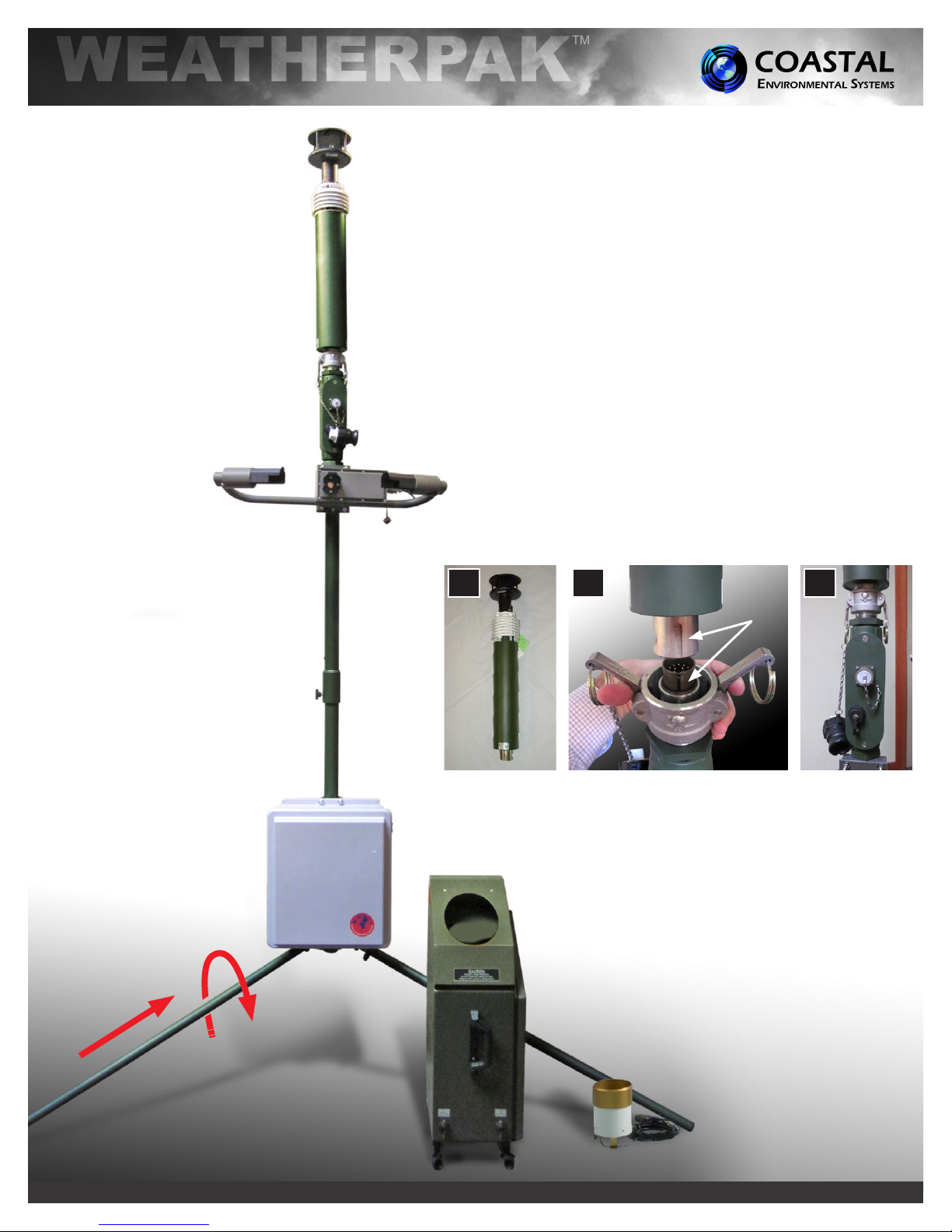
1. Select a level piece of ground about 4 meters in diameter. To
avoid compass error, place the WEATHERPAKTM at least 30
meters, laterally, from any mass of steel (trucks, buildings, etc). In
other words, mounting on top of a van is OK, but right next to it is
not an ideal location.
2. Assemble the lower tower section: Insert the three legs into the
tower base and secure with a turn clockwise, forming a tripod.
Place the tripod in the center of the 4-meter diameter area.
3. Secure the WEATHERPAKTM to the tower top: Line up the
slot on the WEATHERPAKTM bottom connector with the pin
slot in the KamLock connector. Carefully, but rmly, seat the
WEATHERPAKTM into the KamLock (the t is precision-machined
and may require an extra push). Push the arms of the KamLock
clamp down to assure proper installation.
3a
3b
3c
Tower Base
Power Supply
(Battery Box)
Cloud Height Sensor
(Ceilometer)
820 First Avenue South, Seattle, WA 98134 Tel: +1 (800) 488-8291 / +1 (206) 682-6048 Fax: +1 (206) 682-5658 www.CoastalEnvironmental.com
4. Place the entire unit (upper tower section and WEATHERPAKTM)
onto the tripod and turn clockwise to secure. Hand tighten the
screw.
Rain Gauge
4/9/12
Page 2
Tactical Weather Station Set-Up Guide
TM
5 5 5
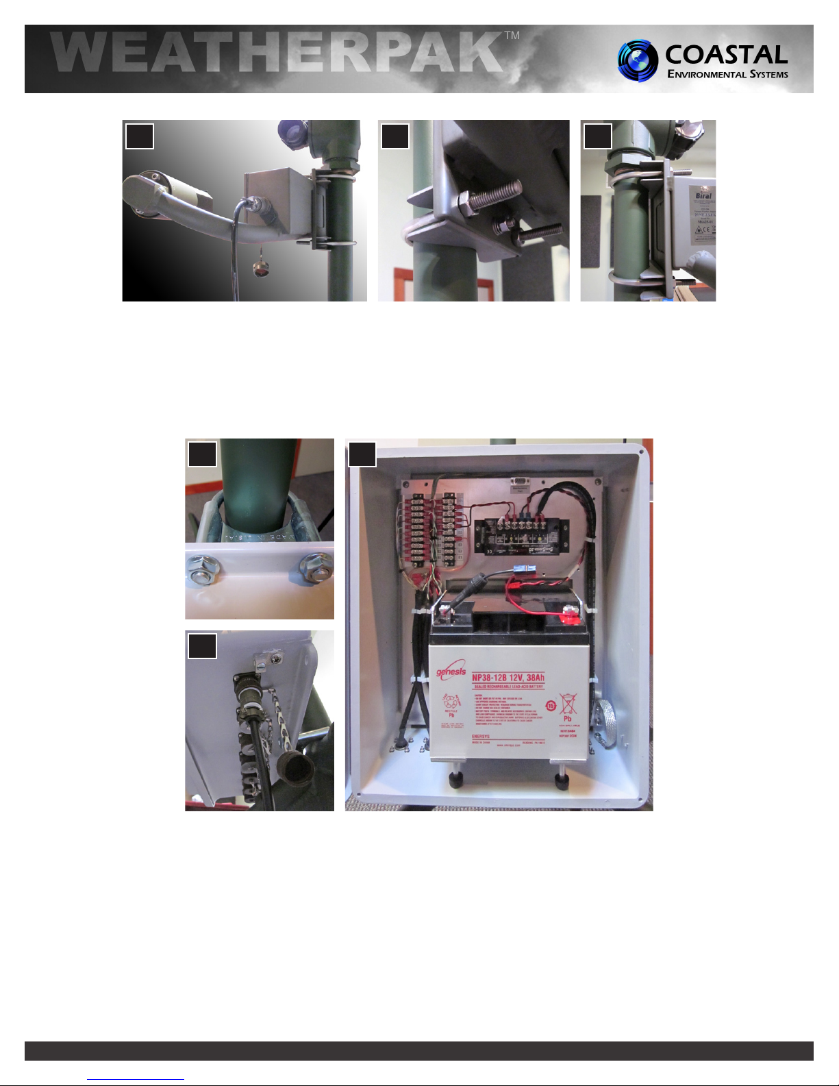
5. Mount the Visibility Sensor to the top tower section, just below the junction box.
6. Place the Rain Gauge on level ground near the tower, but with nothing over the top. Remove the top funnel from the
sensor and verify that the tipping mechanism is able to move freely. Remove anything used to hold the tipping mechanism
in place during shipping.
7. Place the Cloud Height Sensor (Ceilometer) on level ground near the tower.
8
9
9
8. Mount the Power Supply (Battery Box) to the lower tower using the clamps on the rear of the enclosure as shown.
9. Connect all Sensor Cables to the Power Supply (Battery Box) as shown in the Wiring Diagram. Tighten by hand.
820 First Avenue South, Seattle, WA 98134 Tel: +1 (800) 488-8291 / +1 (206) 682-6048 Fax: +1 (206) 682-5658 www.CoastalEnvironmental.com
 Loading...