

Page 1
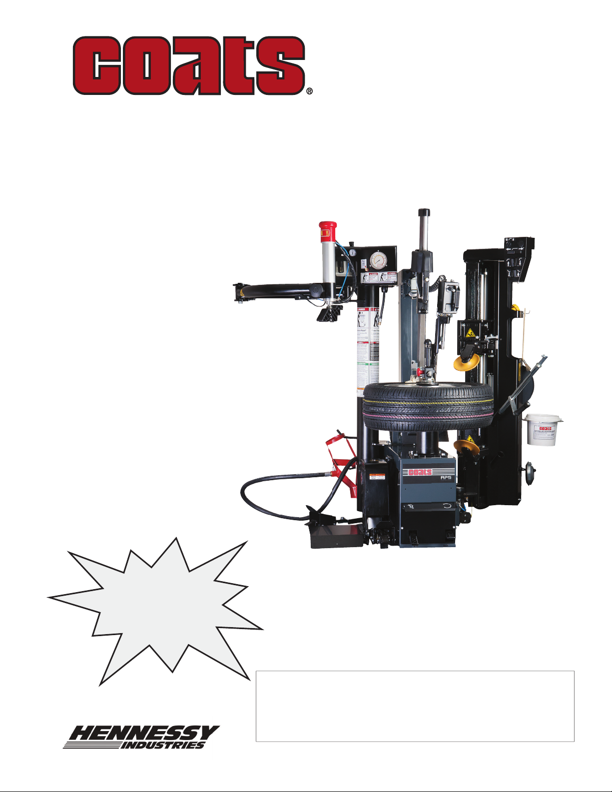
APS 3000
Center Post Tire Changer
For servicing single piece automotive
and most tubeless light truck
tire/wheel assemblies.
Any other type, including tube type agricultrual, require
special handling. Tires identifi ed as truck tires need to
adhere to OSHA standard 1910.177.
See
RIM Safety page 4
ÌOperating
Instructions
on page 6.
Operation Instructions
Safety Instructions
Set Up Instructions
Maintenance Instructions
READ these instructions before placing unit in
service. KEEP these and other materials delivered
with the unit in a binder near the machine for ease
of reference by supervisors and operators.
1601 J. P. Hennessy Drive, LaVergne, TN USA 37086 615/641-7533 800/688/6359 www.coatsgarage.com Manual Part No.: 85610910 00
HENNESSY INDUSTRIES INC. Manufacturer of AMMCO
®
, COATS® and BADA® Automotive Service Equipment and Tools. Revision: 3/17
Page 2

Table of Contents
General Information ................................................ iii
General Safety Instructions .................................... iii
Tire Specifications Diagram .................................... iv
Safety Instructions ................................................... v
Owner’s Responsibility .........................................v
Operator Protective Equipment ............................v
Definitions of Hazard Levels..................................v
Specifications ........................................................... vi
Connections .........................................................vi
Working capacity ..................................................vi
Layout Details ......................................................vi
Safety Devices .......................................................... 1
Safety Notices and Decals ....................................... 1
Warning Decal Placement .................................... 2
Remember R.I.M. ...................................................... 4
Principal Operating Parts ......................................... 6
Pneumatic Systems ............................................. 8
Description of the Machine Controls ...................... 9
Installation ............................................................ 9
Space required for positioning ............................. 9
Tire-Changer placement and connections ............ 9
Connection to the Compressed Air Supply .......... 9
Transport ..................................................................10
Unpacking ................................................................10
Set Up .......................................................................11
Wheel Clamping Operation with Smart Lock ...... 12
Wheel Unlocking ................................................ 12
Tightening Adjustment ....................................... 12
Positioning the Valve .......................................... 13
Tire Classification ................................................... 13
Tire Pressure Monitoring System (TPMS) ............ 14
Bead Loosening ...................................................... 15
Upper Bead Loosening ....................................... 15
Lower Bead Loosening ...................................... 16
Match Mounting ................................................. 16
Tire Demounting ..................................................... 17
Upper Bead Demounting ....................................17
Lower Bead Demounting ................................... 18
Tire Mounting ......................................................... 18
Lower Bead Mounting ........................................ 18
Upper Bead Mounting ........................................ 19
Inflation ................................................................... 20
Stages of Inflation .............................................. 21
Mismatched Tires and Wheels ........................... 22
Tubeless Tire Inflation ......................................... 23
Standard Accessories ............................................. 24
Optional Accessories .............................................. 26
Maintenance ........................................................... 27
Standard Maintenance ....................................... 27
Machine Overhaul .............................................. 28
Troubleshooting Chart ........................................... 29
RIM Chart ................................................................ 32
NOTICE
Read entire manual before assembling,
installing, operating, or servicing this
equipment.
ii • Important: Always read and follow operating instructions.
Page 3

General Information
The tire changer is designed to demount and mount tires of passengers cars and light commercial vehicles with
rims from 10” to 34” (254 - 863 mm) and maximum tire diameter of 47” (1200 mm).
The tire changer is designed to demount and mount conventional tires, as well as new generation types, such
as “self-supporting” RUN-FLAT and low profiled tires, with steel and/or light alloy rims.
The tire changer is NOT suitable for demounting inflated or dirty tires, to straighten rims or to remove wheel
bead wires. As a consequence, all these procedures are FORBIDDEN.
General Safety Instructions
The tire changer is to be used exclusively by qualified and authorized personnel.
A qualified operator is someone who fully understands the instructions described in this manual supplied by the
manufacturer, who has been specifically trained and who is aware of safety standards at the workplace.
Those in charge of using the machine shall not be under the influence of drugs, alcohol or other substances,
which could compromise their physical and mental work capabilities.
For greater safety, operators shall wear protective footwear, gloves, protection goggles and shall NOT wear any
form of clothing that could get caught in machine or restrict the operator’s movements.
The operator must be able to:
• Read and understand the danger warnings.
• Understand the characteristics of the machine.
• Keep unauthorised people away from the work area.
• Make sure the machine is started in full observance of all the applicable safety standards and regulations.
• Make sure all operators are familiar with the machine and how to use it safely and correctly.
• Avoid touching moving parts or pressurised parts without first disconnecting the machine from the
electrical and air power supply.
• Read and ensure full comprehension of the use and maintenance manual to be able to use the machine
correctly and safely.
• Keep the use and maintenance manual with care in an easily accessible place, so that it can be consulted
whenever needed.
The tire changer may only be used by specifically trained and authorized personnel.
Tampering or modifications to the equipment that are not authorised in advance by the manufacturer, relieve the
latter from all forms of liability as regards to damages deriving from or referable to such actions.
Removal or tampering with the safety devices provides grounds to immediately cancel the warranty and in-
volves violation of State and Federal OSHA regulations and codes.
The tire changer is equipped with informative and warning decals which are designed and made to last.
If they should deteriorate, user may request replacement decals.
Important: Always read and follow operating instructions. • iii
Page 4
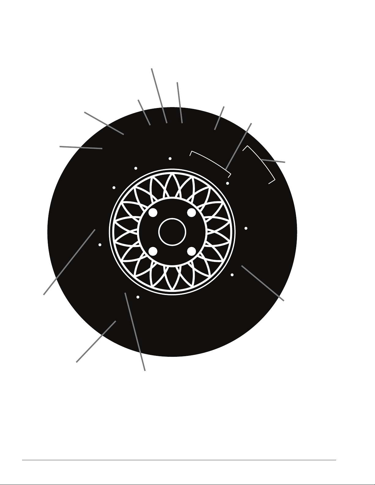
Tire Specifi cations Diagram
Nominal width of
tire in millimeters
Passenger
car tire
Max.
permissible
inflation
pressure
Radial
Ratio of height to
width (aspect ratio)
1
2
P
E
L
A
P
0
S
3
A
I
D
A
R
I
1
D
A
O
L
.
X
A
N
O
I
T
E
R
I
T
A
E
R
N
U
T
A
M
A
R
E
P
M
X
E
R
P
.
A
M
5
3
.
S
S
E
S
B
L
0
T
5
M
C
Rim diameter
code
Load index &
speed symbol
U.S. DOT tire
1
R
5
6
/
S
S
E
L
E
B
U
T
D
R
O
C
X
A
R
T
0
2
5
9
5
H
0
A
R
3
W
T
6
T
R
E
A
S
I
D
E
D
O
T
M
A
L
9
A
B
C
L
L
2
P
L
I
E
S
2
X
X
X
X
E
A
D
W
E
A
2
R
identification number
M
+
S
D
4
P
L
I
E
S
X
X
X
C
O
R
D
M
A
2
X
X
N
U
F
A
C
T
U
R
E
R
Severe snow
conditions
Tire ply
composition
and materials
used
Treadwear, traction
and temperature grades
iv • Important: Always read and follow operating instructions.
Max. load rating
Page 5
Safety Instructions
Owner’s Responsibility
To maintain machine and user safety, the responsibility
of the owner is to read and follow these instructions:
• Follow all installation instructions.
• Make sure installation conforms to all applicable
Local, State, and Federal Codes, Rules, and Regulations; such as State, Federal OSHA Regulations
and Electrical Codes.
• Carefully check the unit for correct initial function.
• Read and follow the safety instructions. Keep them
readily available for machine operators.
• Make certain all operators are properly trained,
know how to safely and correctly operate the unit,
and are properly supervised.
• Allow unit operation only with all parts in place and
operating safely.
• Carefully inspect the unit on a regular basis and
perform all maintenance as required.
• Service and maintain the unit only with authorized
or approved replacement parts.
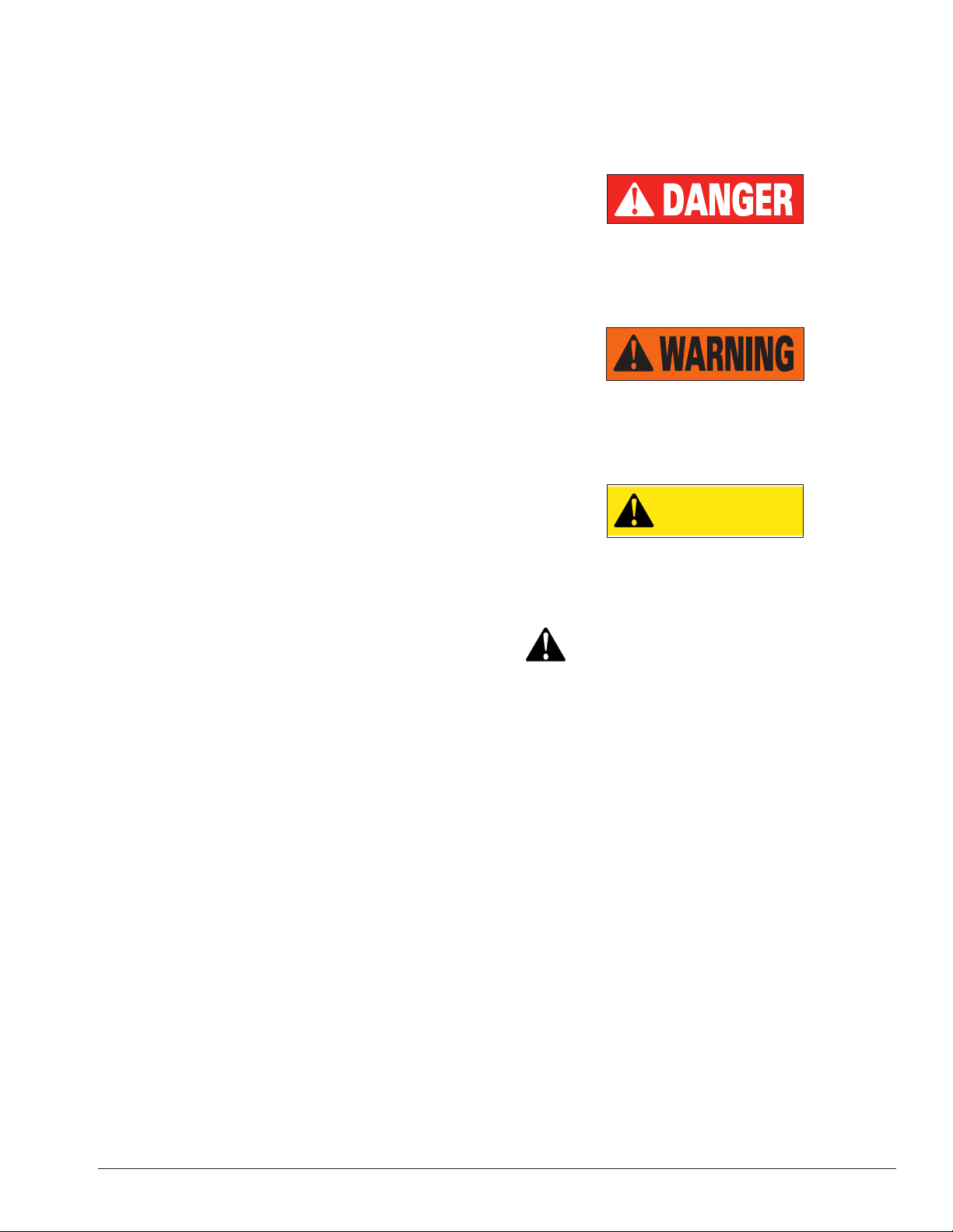
Definitions of Hazard Levels
Identify the hazard levels used in this manual with the
following definitions and signal words:
DANGER
Watch for this symbol:
It Means: Immediate hazards, which will result in
severe personal injury or death.
WARNING
Watch for this symbol:
It Means: Hazards or unsafe practices, which could
result in severe personal injury or death.
CAUTION
Watch for this symbol:
CAUTION
• Keep all instructions permanently with the unit
and all decals/labels/notices on the unit clean and
visible.
• Do not override or bypass safety features.
Operator Protective Equipment
Personal protective equipment helps make tire servicing safer. However, equipment does not take the
place of safe operating practices. Always wear durable
work clothing during tire service activity. Loose fitting
clothing should be avoided. Tight fitting leather gloves
are recommended to protect operator’s hands when
handling worn tires and wheels. Sturdy leather work
shoes with steel toes and oil resistant soles should be
used by tire service personnel to help prevent injury
in typical shop activities. Eye protection is essential
during tire service activity. Safety glasses with side
shields, goggles, or face shields are acceptable. Back
belts provide support during lifting activities and are also
helpful in providing operator protection. Consideration
should also be given to the use of hearing protection if
tire service activity is performed in an enclosed area, or
if noise levels are high.
It Means: Hazards or unsafe practices, which may
result in minor personal injury or product or property
damage.
Watch for this symbol! It means BE ALERT! Your
safety, or the safety of others, is involved!
Important: Always read and follow operating instructions. • v
Page 6
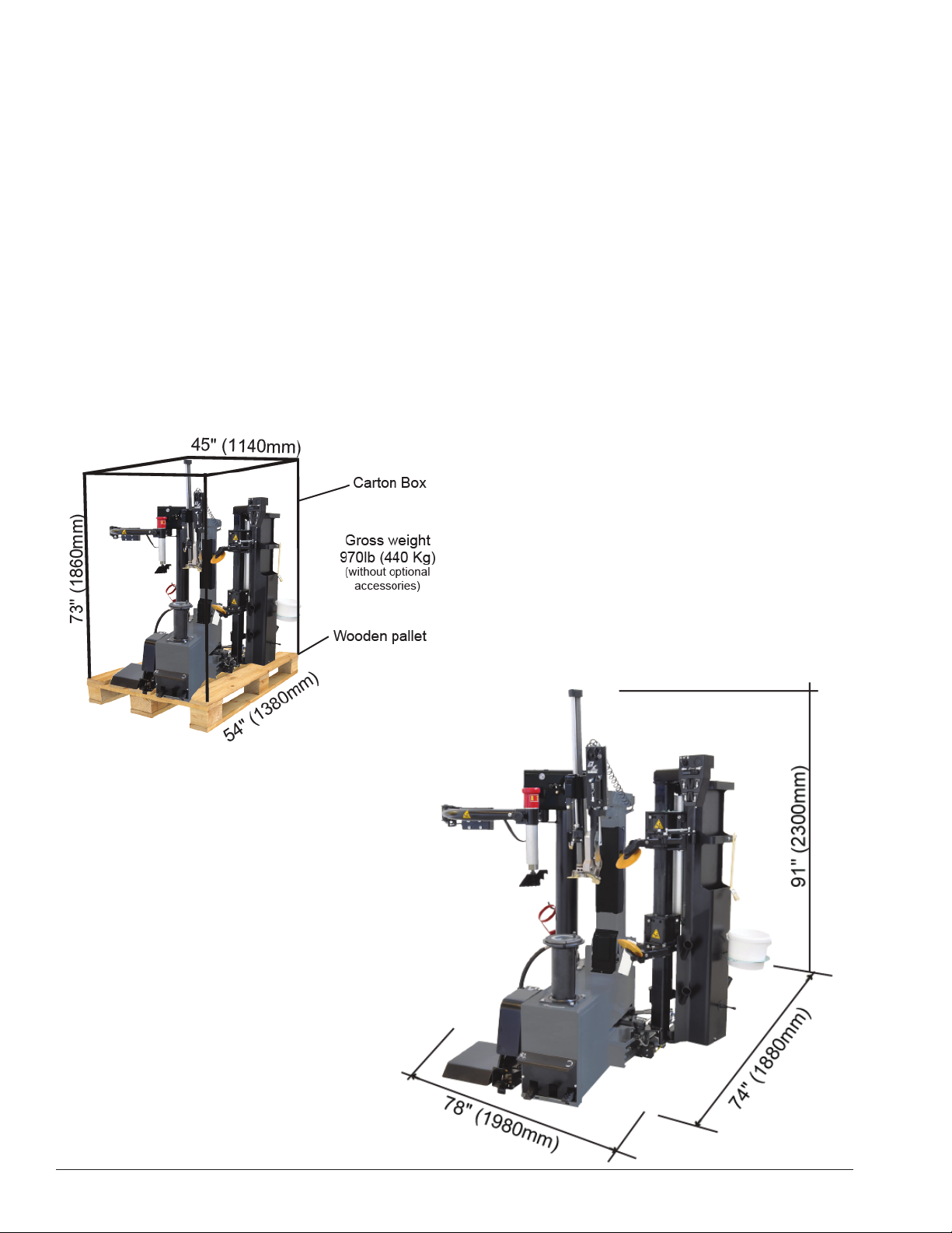
Specifi cations
Connections:
Power supply: 230V - 50/60 Hz - 1Ph
Operating pressure: 116 - 145 psi
Air supply pressure regulator set at 145 psi
Inflating air-pressure regulator set at 50 psi
Working Capacity:
Rim clamping range: 12” to 34”
Maximum rim width: 16” (406 mm)
Maximum wheel diameter: 47” (1200 mm)
Layout Details:
Minimum overall dimensions mm: 47” x 51” x 70” (1180mm x 1300mm x 1770mm)
Net weight (optional accessories excluded): 870 lb (395 kg)
Operating temperature range: min 41° to 122° F (5° C max 50° C)
Packing Details
Overall Dimensions
vi • Important: Always read and follow operating instructions.
Page 7
Safety Devices
The tire changer is equipped with safety devices that are designed to guarantee the safety of the machine
operator:
Pneumatic safety valve, arranged inside the machine that prevents the pressure from exceeding 58 PSI
during inflation.
Pressure regulator and gauge that limits the maximum pressure of the circuit to 145 PSI.
Maximum tank pressure valve, fitted on the tank, to prevent the maximum pneumatic pressure from exceeding
160 PSI (optional auxiliary bead seater)
Safety Notices and Decals
Failure to follow danger, warning, and caution instructions may lead to serious personal injury or
death to operator or bystander or damage to property. Do not operate this machine until you read
and understand all the dangers, warnings and cautions in this manual. For additional copies of
either, or further information, contact:
For additional information contact:
Hennessy Industries, Inc.
1601 JP Hennessy Drive
LaVergne, TN 37086
(615) 641-7533 or (800) 688-6359
www.coatsgarage.com
Rubber Manufacturers Association
1400 K Street N. W., Suite 900
Washington, DC 20005
(202) 682-4800
www.rma.org
Tire Guides, Inc.
The Tire Information Center
1101-6 South Rogers Circle
Boca Raton, FL 33487
(561) 997-9229
www.tireguides.com
Important: Always read and follow operating instructions. • 1
Page 8
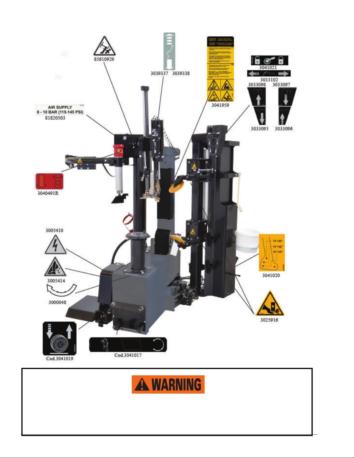
Warning Decal Placement
Replace any warning label immediately in case of damage or loss.
Do not operate the Tire Changer in case of missing warning labels.
Do not hide any warning label by any means. Do not place objects that can obstruct or reduce the
visual ability of the operator. Refer to the above mentioned codes for ordering warning labels.
2 • Important: Always read and follow operating instructions.
Page 9
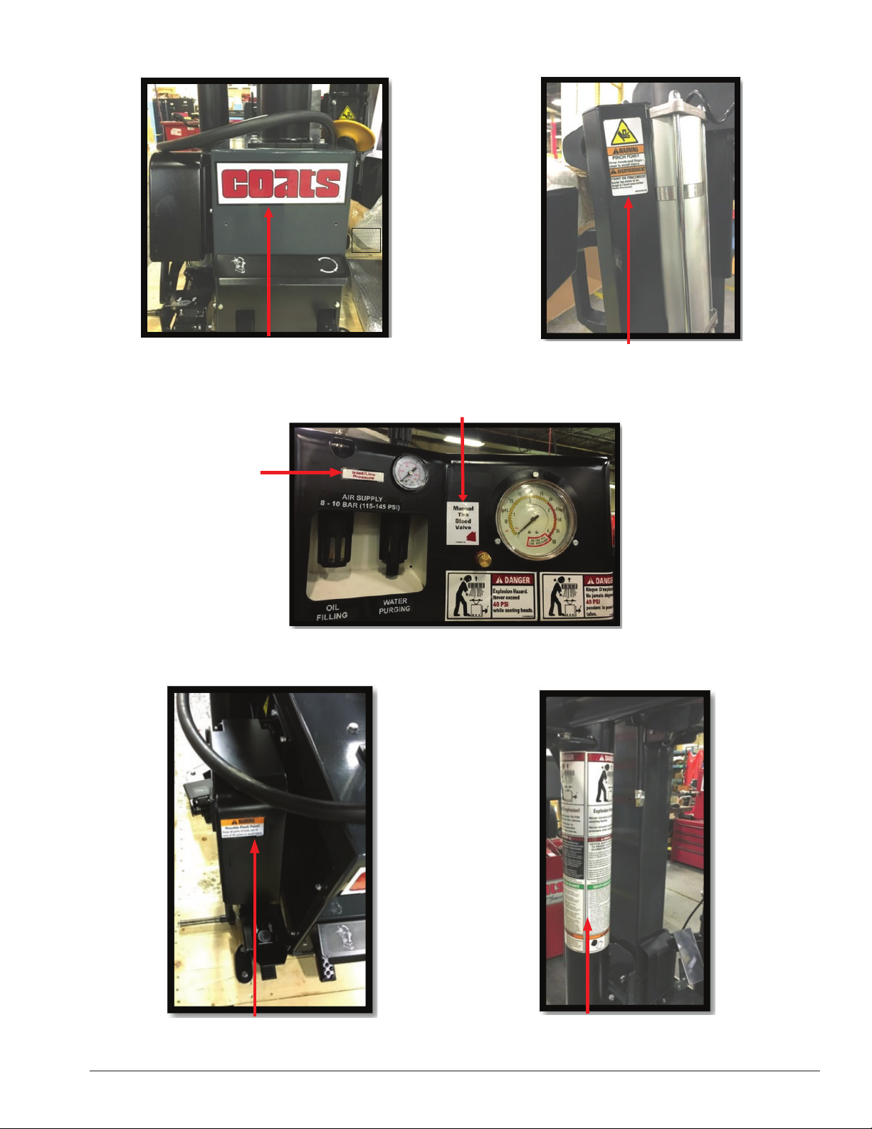
Warning Decal Palcement (cont.)
Main Coats
85608119
Front of the machine
Inlet Pressure
8182059
Pinch Point
85610705
Manual Tire Bleed
8183597
Danger Explosion (2x)
8109888 / 8109888Fr
Pinch Point
85609356
Tower
8182373 and FR
Important: Always read and follow operating instructions. • 3
Page 10
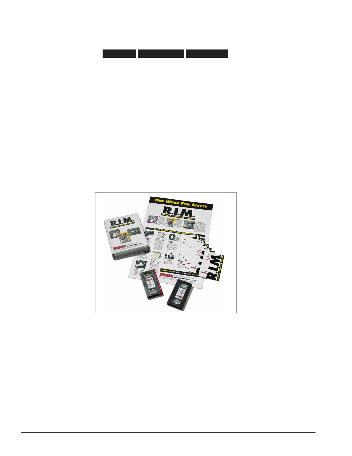
Remember R.I.M.
Three Simple Steps To Help Keep Shops Safe
READ INSPECT MOUNT
R.I.M. is a training program developed by Hennessy Industries to help keep tire technicians safe. By following
the basic principles of R.I.M., technicians can avoid situations that can cause catastrophic accidents like tire explosions.
R.I.M. stands for read, inspect, and mount:
Read the tire size on a new tire before mounting to make sure it is the proper size for the wheel.
Inspect the wheel for cracks, rust, and or other damage that could cause an unsafe situation.
Mount the tire safely, making sure not to put any part of your body over the tire during inflation.
The most serious of possible accidents is a tire explosion. This is often caused by a tire/rim mismatch.
If a tire explodes on a tire changer, pressure causes it to fly straight up at tremendous speed. If a technician is
standing over the tire, he can be seriously injured or killed.
Hennessy’s R.I.M. program allows the technician to avoid situations that can cause tire explosions and other
accidents. The full program, including training videos, brochures, posters, and other materials, are available from
Coats distributors nationwide.
4 • Important: Always read and follow operating instructions.
Page 11

Intentionally left blank
Important: Always read and follow operating instructions. • 5
Page 12
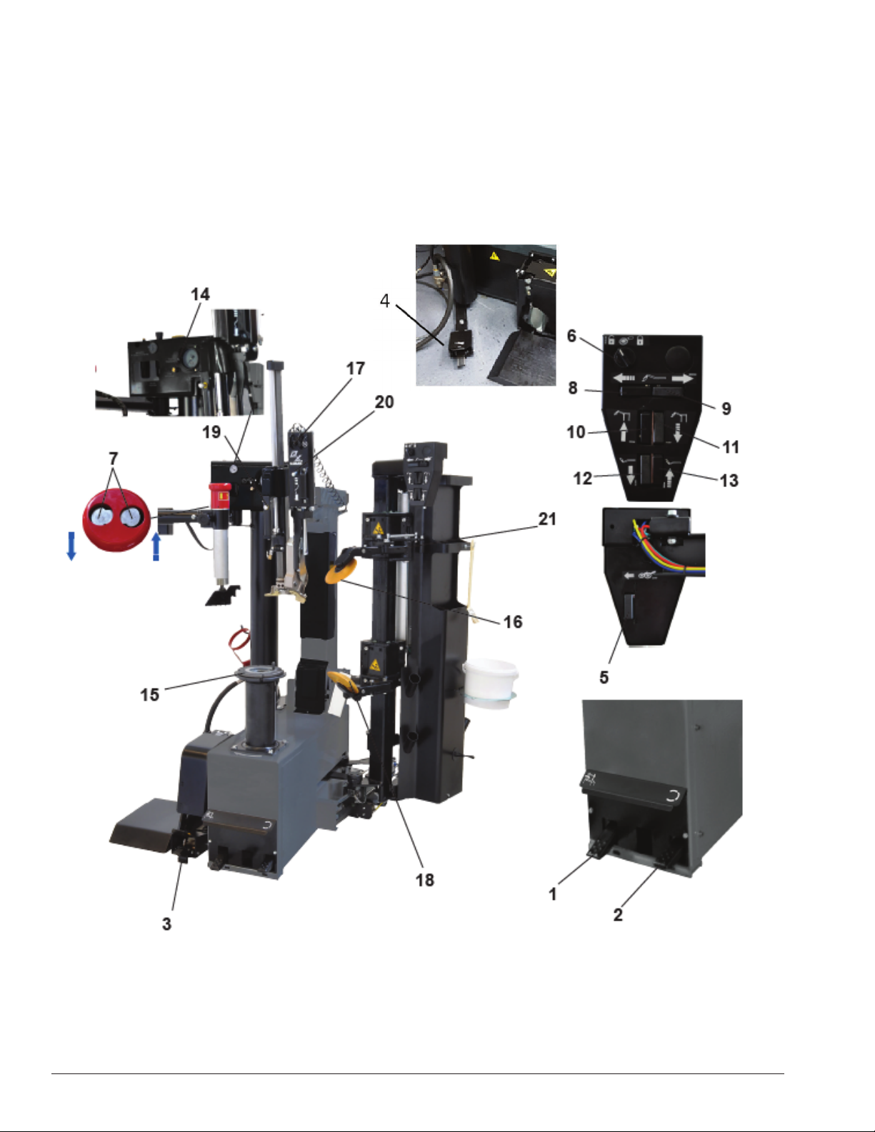
Principal Operating Parts
Do It Now!
Now is a good time to contact product service (800688-6359) to start warranty, otherwise warranty starts
at time of shipment.
Know Your Unit
Compare this illustration with the unit before placing it
into service. Maximum performance and safety will be
obtained only when all persons using the unit are fully
trained in its parts and operation. Each user should learn
the function and location, of all controls.
Prevent accidents and injuries by ensuring the unit is
properly installed, operated and maintained.
6 • Important: Always read and follow operating instructions.
Page 13

CAUTION
Replace any damaged or missing safety decals. They are available from COATS, (800) 688-6359.
1 Tilting tower control pedal
2 Clockwise and counterclockwise clamping chuck (15) rotation control pedal
3 Wheel lifter (optional) control pedal
4 Inflation pedal
5 Button used to activate the “over-run” function of bead loosener disks (16 and 18)
6 Selector used to block the bead breaking carriage and to activate the “over-run” function (5)
7 Bead pressing arm control buttons (up/down)
8 Bead breaking carriage “forwards” movement button
9
Bead breaking carriage “backwards” movement button
10 Upper bead loosener disk lifting button
11 Upper bead loosener disk lowering button
12 Lower bead loosener disk lowering button
13 Lower bead loosener disk lifting button
14 Deflation button
15 Clamping chuck
16 Upper bead loosener disk
17 Lerevless mode control switch
18 Lower bead loosener disk
19 Operating arm control button
20 Leverless tire mounting/demounting system control switch
21 Upper bead loosener arm opening control
Important: Always read and follow operating instructions. • 7
Page 14

Pneumatic Systems
8 • Important: Always read and follow operating instructions.
Page 15

Description of the Machine Controls
Installation
Space required for positioning
When choosing the place of installation be sure that it
complies with current safety-at-work regulations.
The Tire-Changer must be connected to the main
electric power supply and the compressed air system. It
is therefore advisable to install the machine near these
power sources.
The installation area must leave at least the room shown
in picture “fig. 1”, so as to allow all parts of the machine
to operate correctly and without any restriction.
Lighting should be adequate to perform safe operations
and comply with the current regulations for safety at
work.
Tire-Changer placement and connections
Place Tire-Changer onto a flat, smooth and not slippery floor with a suitable load capacity.
The machine need not necessarily be anchored to the ground, but if you prefer to do so, drill 2 deep holes (100
mm) on the ground in correspondance of 2 holes of the machine rear base by using a 10 mm drill bit of suitable
length. Insert the two brackets A and B into the machine base from the front, and drill two holes
the same as previous ones. Insert suitable metal anchor dowels in the holes drilled and secure firmly.
28”
(700mm)
If the machine is installed outside it must be protected by a appropriate lean-to shed. The installation site should
be equipped with an electrical system with an adequate grounding circuit equipped with an appropriate ground
fault 16A circuit breaker, power indicator light, placed in a visible and accessible place by the operator.
NOTE: If the machine is supplied without the electrical plug, the user shall install a 20A plug suitable for the
voltage of the machine and complies with current regulations.
Before connecting the machine, ensure pneumatic and electrical supplies meet those indicated
on the machine’s data plate.
• Even small electrical system jobs must be performed out by qualified personnel.
• The Manufacturer is not responsible for damages caused by electrical connection different from
those on the machine’s data plate.
• Unplug the unit from electrical and pneumatic supplies before moving and servicing.
• During the first connection to the compressed air, attention must be paid to the movement of
certain parts of the machine, which may be sudden and unexpected, creating potential hazards
in the action area.
Connection to the Compressed Air Supply
The pneumatic supply must be a minimum of 116 psi.
Connect the machine to the compressed air supply by the quick
disconnect located at the rear of the machine (Fig. 2).
Important: Always read and follow operating instructions. • 9
Page 16

Transport
The Tire Changer must be transported in its original packaging and kept in the position
indicated on the box.
The packaged machine must be moved with a fork lift of suitable capacity.
Please insert the forks as shown in fig. 1.
Unpacking
Remove the protective cardboard, remove all fixing screw and free the Tire-Changer from its original pallet.
Check the condition of the machine, making sure that no part is damaged or missing, by referring to the picture
on page 10.
If in doubt, please do not use the machine and get in touch with your Distributor for further steps.
Keep packing elements away from children.
All packing elements must be stored in the proper stocking areas.
Note: All the most delicate surfaces of the Tire Changer are coated with a special rust-proof oil.
Some oil traces may leak after coating procedure: please, remove them as necessary.
Use lifting equipment of suitable load-bearing capacity that is able to take the weight of the tire changer.
To lift the machine (fi g. 2), use a transport strap with minimum load-bearing capacity of 970 lb. (440 kg).
After tire changer positioning, take off the transport strap.
After having positioned the machine, in its fi nal
location, remove the accidental tilting safety pin from the
arm (fi g. 3).
Put the pin together with the other standard
accessories delivered with the machine, for any future
need.
10 • Important: Always read and follow operating instructions.
Page 17

Set Up
Connect the machine to the electrical power supply, which must have line fuses and an efficient grounding
system, meeting current standards. It must also be connected to an automatic differential 20A circuit breaker.
NOTE: If the machine is not supplied with an electrical plug, the user shall install a 20A plug that is suitable for
the voltage of the machine and complies with current standards.
Connect the machine to the compressed air supply using the fitting on the lubricator on the back of the
machine.
Loosen the control panel bracket locking cap screw and pivot cap screw, adjust it to a convenient position
for operation, then tighten the cap screw.
Important: Always read and follow operating instructions. • 11
Page 18

Wheel Clamping Operation with Smart Lock
1. Check the correct wheel positioning on the clamping chuck.
Insert SMART LOCK making the centering cone fi t the rim hole
correctly, leaving no space among SMART LOCK nut, the rim and the
Tire-Changer clamping chuck.
2. Keeping the handle pressed down (to avoid residual play),
tilt the locking lever vertically.
3. During wheel clamping operation the Quick-Release system moves
automatically to hooking position (click).
Check the perfect wheel locking onto the clamping chuck before
performing any bead breaking, demounting or mounting operation.
Plastic protection to avoid
any damage to alloy rim
Wheel Unlocking
4. Once the operations on the wheel are completed,
lift up the Quick-Release system outer sleeve.
5. Tilt down the locking lever to unlock SMART LOCK,
in order to pull out the locking nut and remove the
wheel from the clamping chuck.
Tightening Adjustment
The clamping force of SMART LOCK could be loosened after a long time use by a progressive wearing of some
components, this revealed by a progressive slack of the locking lever.
To restore / increase / decrease the SMART LOCK tightening: press the yellow adjustment button and,
by means of the adjustment knob, start turning manually the conical terminal thus acting on the expanding nut.
Then, release the button and keep on turning the conical terminal until the button pops up again.
12 • Important: Always read and follow operating instructions.
Page 19

Positioning the Valve
Fig. 6 shows a rim in the form of a clock. In the following
Mounting and Demounting process steps, you will position
the rim with clock directions, so that the valve and pressure
sensor do not get damaged.
CAUTION
To avoid damaging the valve and pressure sensor,
(if installed) you must always arrange the valve in
the position indicated, following the instructions
when mounting and demounting the tire. fig.6
Tire Classifi cation
LOW PROFILE tires (UHP) are those in which the height (H) and the width (C) have a ratio lower than 0.5 (i.e.
low profile series 45 stands for a ratio of H/C = 0.45).
For tires to be considered as LOW PROFILE (UHP), they must also have a maximum speed code of equal to
or higher than V.
RUN-FLAT tires are those which, even when they have no internal pressure, allow you to continue to drive the
vehicle for a preset number of miles and at a preset speed. These parameters change from one manufacturer to
another. The market currently offers 2 different types of RUN-FLAT tires:
• Those with REINFORCED SIDE (SELF-SUPPORTING) where, thanks to a different mix and a reinforced
structure, the shoulder of the tire is able to bear the weight of the vehicle even when the pressure in the tire
is zero.
• Those with INTERNAL SUPPORT have a ring inside the rim that bears the side of the tire when there is no
pressure inside it. The internal support may be made of plastic or metal.
The tire changer is able to handle all types of LOW PROFILE (UHP) and all types of RUN-FLAT tires with
REINFORCED SIDE; for other types, refer to the specific instructions of the dedicated accessories, if available.
The mounting and demounting procedure is the same, be it a RUN-FLAT tire with REINFORCED SIDE (SELFSUP-PORTING) or a LOW PROFILE tire (UHP).
CAUTION
It is crucial to follow the instructions very carefully in order to avoid irreparable damages to the tire,
which could compromise the vehicle’s safety.
Important: Always read and follow operating instructions. • 13
Page 20

Tire Pressure Monitoring System (TPMS)
TPMS, Tire Pressure Monitoring System is an electronic system designed to monitor the air pressure inside the
tires through special sensors mounted inside the wheels, which provide real-time tire-pressure information and
inside temperature data to the vehicle’s electronic control unit. Tire pressure system alerts the driver when the
tire pressure falls 20% below the recommended pressure, thus increasing your safety on the road.
This chapter describes the correct positioning of TPMS valve during the different working stages, in order to
avoid any damage.
Bead Loosening:
Place TPMS valve at “2:00 o’clock” position.
Start pushing on the tire bead using the upper
bead loosening disk.
Demounting tool positioning:
Place TPMS valve at “2:00 o’clock” position. Bring the
demounting tool into working position. While spinning the
wheel, insert the demounting tool into the drop center
level. Stop tire rotation when the valve reaches 11 o’clock
position.
Upper Bead demounting:
Spin the clamping chuck (clockwise) by pressing pedal 1
until the valve reaches “1 o’clock” position (at about 10 cm
from the demounting tool) so as to avoid possible damages
to the TPMS valve.
Warning: Rim and Tire must spin together as one,
during bead demounting operations, to avoid displacement
of TPMS sensor.
Lower Bead demounting, with demounting tool:
Place TPMS valve below the demounting tool at
“12:00 o’clock” position.
Lower Bead demounting, with bead loosening disk:
Place TPMS valve towards the bead loosening disk.
Lower Bead mounting:
Place TPMS valve at “5:00 o’clock” position, in any case
at about 10 cm from traction point.
Upper Bead mounting:
Place TPMS valve at “5:00 o’clock” position, in any case
at about 10 cm from traction point.
14 • Important: Always read and follow operating instructions.
Page 21

Bead Loosening
Ensure the tire is completely deflated before starting any operation on the wheel.
Before lifting and positioning the wheel onto the clamping chuck, use the proper tool to remove any weights
from the rim, paying attention to not damage the rim.
Before starting any operation, check for the presence of a pressure sensor. If equipped, check its operation with
a dedicated diagnostic tool.
It is possible to unlock the disk support and enable a spring loaded movement, changing the angle of the disk,
increasing its penetration inside the rim. Particularly effective with soft tires.
Upper Bead Loosening
Check the correct centering and locking of the wheel onto the clamping chuck.
Check that the upper disk arm is in the working position.
Turn switch 6 to unlock the bead loosener and position it by pressing buttons 8, 9, 10 and 11 on the
console, so that the distance between the upper disk and the rim edge is 5 mm (fig. 1), then lock the bead
loosener by turning switch 6 again.
Pay special attention to the valve sensor position, if any, during bead breaking operations.
Wrong movements of the bead loosening disks could damage the sensor.
Spin the clamping chuck until the valve is in the
3 o’clock” position.
Lower the bead loosener disk until it touches the tire using
controls 10 for lifting and 11 for lowering.
Start spinning clockwise.
Note: the clamping chuck can spin at 2 different speeds, according to operator’s preferences.
While spinning the wheel, push the upper bead loosener
disk down below the edge of the rim, then press and hold
down the “over-run” function button 5 while gradually lowering the bead loosener disk until the bead is removed from
the rim.
As soon as enough space is available, a proper tire lubricating paste should be carefully applied to both the inner
surface of the rim and the tire bead (fig. 2).
Avoid contacting pressure sensor with lube paste if installed.
Once the bead is loosened, using button 10 to raise the upper bead loosening disk and move away.
Important: Always read and follow operating instructions. • 15
Page 22

Lower Bead Loosening
Keep the bead loosener system set up as for upper bead
loosener disk procedure: the lower bead loosener disk is
always aligned with the upper one, and it is already positioned
at 3-4 mm from lower rim edge.
Lift the lower bead loosener disk until it touches the lower tire
bead using controls 13 for lifting and 12 for lowering.
Rotate wheel clockwise.
While spinning the wheel, push the lower bead loosener disk
up above the edge of the rim, then press and hold down the
“over-run”function button 5 while gradually lifting the bead
loosener disk until the bead is removed from the rim.
As soon as enough space is available, carefully apply tire lube paste to both to the rim inner surface and to the
tire bead (fig. 2).
NOTE: For a better view and control of the lower bead loosening, use the mirror mounted on the main frame.
fi g. 2
While lossening the bead, just press on the bead and never on the side of the tire.
Match Mounting
Driving could be affected by vibrations caused by
deformations of the rim and/or tire. To optimize the
wheel-balancing, it is necessary to position the wheel
onto the Tire Changer again to bead loosen and lubricate
the rim and the tire, spinning the tire around the rim to a
proper position.
Both upper and lower disks make this process easier,
by gently holding the tire steady while the clamping
chuck spins the rim until the correct matching position is
reached.
16 • Important: Always read and follow operating instructions.
Page 23

Tire Demounting
Once the bead loosening process is completed, and the wheel is already positioned on the clamping chuck,
check and ensure its locked and centered.
Upper Bead Demounting
Bring the tilting tower close to the wheel by pressing pedal 1, while simultaneously placing the mounting tool
over the rim edge using the handle (fig. 1). Set the locking button 19 to position 1 (fig. 2) to lower the
operating arm, then lock everything by setting the locking button in position 2. In this way the mounting tool will
automatically move to the right distance from the rim, at about 2 mm.
Rotate the clamping chuck by pressing pedal 2 until the valve is in the “1 o’clock” position (roughly 10 cm dis-
tance from the mounting tool) in order to avoid possible damages to the valve or pressure sensor - if equipped.
Lower the lever 20 to insert the mounting tool between the bead and the rim edge. The mounting tool should
penetrate enough to hook the tire bead to let the operator complete the tire demounting.
Slowly spin the clamping chuck until the mounting tool is positioned correctly. This will facilitate mounting tool
penetration and tire hooking.
By gently pushing the lower bead loosener disk against the tire lower sidewall and the pneumatic bead pressing
arm against the upper sidewall at the “6 o’clock” position, it will be easier to fit the tool into position (fig. 4).
As soon as the bead is perfectly hooked, lift the mounting tool using the
lever 20 to pull out the bead.
To make the lifting easier, set the bead pressing arm at “6 o’clock”
position and press the sidewall (fig. 4) using pneumatic bead pressing
arm.
Press down pedal 2 to rotate the wheel clockwise until the upper bead is
completely off the wheel rim.
NOTE: Rim and Tire must spin together as one. To help the upper bead off
the Rim and reduce the stress to the Tire, insert the plastic lever
(fig. 5) and spin the wheel clockwise while lifting the tire with the lower
bead loosener disk.
Important: Always read and follow operating instructions. • 17
Page 24

Lower Bead Demounting
Press pedal 1 to move the mounting arm away from the
working position.
Before pulling out the lower bead, spin the clamping chuck
to let the valve reach “1” or “2” o’clock position in order to
avoid possible damages to the valve and the pressor sensor
- if equipped.
Raise the lower bead loosening disk to lift the tire until the
lower bead is 1 cm over the upper rim edge (fig. 1).
Spin the wheel clockwise until the tire is completly off Rim.
Check the pressure sensor - if equipped - and replace if
necessary.
NOTE: Rim and Tire must spin together as one.
To help the lower bead off the Rim and reduce the stress to the Tire,
insert the plastic lever and spin the wheel clockwise while lifting the
tire by the lower bead loosener disk.
Tire Mounting
Check the rim and the tire carefully, as per instructions on pg. 4.
If the rim has been removed, lock it again onto the centrer plate
per instructions on pg. 12.
Carefully lubricate the whole inner surface of the Rim and the
beads of the Tire, both externally and internally around the
circumference, for a width of at least 3 cm.
Avoid contacting pressure sensor with lube paste if equipped.
Lower Bead Mounting
Put the Tire on the Rim with it tilted at “12 o’clock” position in
order to make both upper and lower beads go under the upper rim
edge.
Press pedal 1 to approach the mounting arm and position the
mounting / demounting tool on the Rim edge.
Incline the tire down at the “3 o’clock” position, driving the lower
bead on the mounting tool in order to put the lower bead over its
left side and under it on its right side.
Rotate the wheel clockwise by pressing the pedal 2, while
pressing the tire manually at “5 o’clock” position until the lower
bead reaches the drop center level. Keep the tire pressed while
rotating up to “8 o’clock” position to complete the lower bead
mounting.
18 • Important: Always read and follow operating instructions.
Page 25

Upper Bead Mounting
Keep the mounting arm and the mounting tool in working position and proceed with mounting of the upper
bead, then put the tire bead on the rim slightly tilted down to “3 o’clock” position, so that the upper bead rests
on the left side and under the right side of the mounting tool (fig. 1).
Bead correctly positioned over the left side of the
mounting tool and under it on its right side.
Press the pedal 2 to rotate the wheel clockwise, contemporarily press the tire manually from “5 o’clock”
position to force the upper bead at drop-centre position. Keep it pressed while rotating up to “8 o’clock” position
to complete the upper bead mounting (fig. 2).
It is advisable to use the pneumatic bead pressing arm (fig.2) for standard tires that are particularly difficult to
bead loosen. (fig. 3).
Press the buttons (fig. 4) to use using the bead pressing tool to push on the tire bead at “5 o’clock” position,
press pedal 2 and rotate the tire until it is completely mounted. Once the bead has been mounted, the bead
pressing tool will automatically return to the rest position.
Bead correctly positioned over the left side of the
mounting tool and under it on its right side, thus it
can be slightly lowered for easy tire mounting.
Ensure that the Rim and Tire always spin together.
Important: Always read and follow operating instructions. • 19
Page 26

Infl ation
NEVER exceed tire manufacturer's recommended air pressure. Tires can explode,
especially if inflated beyond these limits.
Use clip-on air chuck, keep hands, arms
and entire body back from inflating tire.
Avoid distraction during inflation. Check
tire pressure frequently to avoid over inflation. Excessive pressure can cause tires to
explode, causing serious injury or death to
operator or bystander.
Manual Release Valve
If you change tires defined as truck tires,
they must be inflated per OSHA instructions.
1. Ensure both beads are seated. When both beads
are seated, the tire is ready for inflation.
2. Replace the valve core if it was removed.
3. Depress the inflation pedal to position 2 to inflate
the tire. The pressure limiter will cycle the air flow as
described earlier. On most tires, the pressure limiter
will cease air flow at approximately 60 PSI. On smaller
volume tires the pressure may be higher.
4. Release air pressure from tire by pressing the
manual deflation button (fig. 27). Inflation hose must
be attached to the valve stem. Never add or adjust tire
pressure using an air hose without a clip-on air chuck
and in-line valve. Do not use a hand-held style chuck
(figure 28).
5. Important: When inflating tires that require more
than 60 PSI, always use a safety cage and air hose with
a clip-on air chuck and in-line valve. The air hose must
have enough length between the chuck and the operation/in-line valve to allow the operator to stand outside
the trajectory.
Figure 27 - Location of Deflation Button
Figure 28 - Do Not Use a Hand-held Style Air Chuck
Explosion Hazard
Never exceed 40 PSI while
seating beads. If you use
more than 40 PSI always
use safety cage.
Remember R.I.M.
(see page iv and back cover)
Explosion Hazard
Never infl ate tire
above
manufacturer’s
recommended
pressure after
bead is seated.
20 • Important: Always read and follow operating instructions.
Page 27

Stages of Infl ation on a
Conventional Tire and Rim
Review these descriptions and diagrams carefully. Refer to them as
necessary during bead sealing, bead seating, and inflation to verify that
you are proceeding properly and safely.
Bead Sealing
Bead sealing is the process of capturing air pressure between the
tire and the rim. The tire will usually contain about 1/2 to 2 PSI at initial
bead seal.
Bead Seating
Bead seating usually occurs on the long tapered side of the wheel
first and the shorter side last. Bead seating will usually require at least
7 PSI in the tire. 40 PSI is the maximum safe pressure at this stage
regardless of tire operating pressure. For tires requiring more than 40
PSI to bead seat use safety cage.
Most European import cars and many aftermarket alloy wheels are
very tight and can be difficult to bead seat. Also note that asymmetrical
hump and run-flat tires are extremely difficult to bead seat. Follow tire
manufacturer’s recommended procedure for bead seating.
Inflation
After the beads are seated, the tire is ready to be inflated. Do not
inflate the tire above the manufacturer’s recommended pressure as
stamped on the tire sidewall. The typical inflation pressure for automobile tires is between 24 and 45 PSI. Light truck inflation pressure
typically covers a wider range.
Important: Always read and follow operating instructions. • 21
Page 28

Mismatched Tires and Wheels
Never mount and inflate mis-matched tires and
wheels.
Mismatched tire and wheel combinations will explode,
if you attempt to force a bead seat, causing personal
injury or death to operator and/or bystanders.
22 • Important: Always read and follow operating instructions.
Page 29

NOTE: Sometimes, regular inflation may not be enough to seat the bead of tubeless tires.
This problem may be solved by using the optional accessory TUBELESS INFLATING DEVICE.
Tubeless Tire Infl ation
In order to properly use the optional Tubeless Inflating Device:
Press the safety valve against the rim border, push the activating
button on the handle to blast air and press the inflating pedal 4
to provide air to the wheel valve.
During the inflation stages (and especially during the bead seating operation), you must wear
appropriate personal protective equipment to protect your hearing from possible blast injuries
and from noise levels that sometimes exceed the permitted threshold.
Also use appropriate protection equipment to protect your eyes from possible debris that might
fly due to the high pressure air involved in tire bead seating.
Due to the high pressure air that comes out of the jet when operating the inflating device,
hold the handle firmly with your hand to avoid any backlash.
Important: Always read and follow operating instructions. • 23
Page 30

Standard Accessories
Lube Paste Bucket
(PN 8183710)
Brush
(PN 85000850)
Plastic protections for mounting/demounting tool
(PN 85000850)
Plastic protections for Smart Lock centering cone
(PN 89231516)
Rubber protections for clamping chuck
(PN 89231517)
Plastic protections for clamping chuck driving pin
(PN 89231518)
Plastic cone Ø 70 mm for clamping special alloy rims
(PN 83040730)
Manual Bead Depressor
(PN 89237711)
Bracket Pin
• pin (PN 83036303)
• washer (PN 83040636)
• nut (PN 84394168)
24 • Important: Always read and follow operating instructions.
Page 31

Standard Accessories (cont.)
Adjustment knob for Smart Lock
(PN 82041474)
Cleaning brush for Smart Lock and clamping chuck inner surface
(PN 84292291)
O rings for Smart Lock
• (1) (PN 84293252)
• (2) (PN 84298601)
Air lubricator, air filter/water trap
(PN 82041007)
Wheel lifter for wheel positioning and centering onto
clamping chuck. Lift capacity: 176 lb. (80 kg.)
(PN 89240910)
Tubeless Inflation Device external kit
(PN 89241008)
3 Pin Extensions
• (1) 33mm (PN 83032133)
(2) 72mm (PN 83031335)
•
Important: Always read and follow operating instructions. • 25
Page 32

Optional Accessories
Wheel clamping adaptor, allows clamping reverse mounted
wheels, wheels with no center hole and special wheels (BMW
rims). Suitable to lock any rim with any holes-number onto the
clamping chuck. (PN 89242832)
Reverse mounted wheels Wheels with no center hole Special rims
Truck cone kit, allows clamping VAN and LCV wheels
with center hole diameter from 110 to 190 mm.
(89219117)
Truck cone kit, allows clamping VAN and LCV wheels
with center hole diameter from 140 to 220 mm.
(89219126)
Double face cone for light trucks, allows clamping
VANs and LCVs wheels with center hole diameter
from 75 to 145 mm. (89234456)
Cone for thin steel rims and center hole diameter
from 75 to 120 mm. (89233680)
26 • Important: Always read and follow operating instructions.
Page 33

Maintenance
Standard Maintenance
Routine maintenance according to the following instructions is of crucial importance to ensure the correct
operation and lasting life of the Tire Changer.
Unplug the unit from electrical power source and compressed air supply before servicing it.
Release the compressed air from the circuit by pressing the deflation button 14 for a few seconds.
On daily basis, keep the machine clean of any dirt to ensure the smooth movement of slides,
carriages, and tools and to ensure the correct functioning of clamping chuck and locking systems.
On daily basis, check for worn or damaged plastic mounting tool inserts and plastic and rubber
protections in order to protect alloy rims.
In case of wear or damage, replace them with new inserts and new protections.
Every 2-3 days, check the oil
dropping into the cup (1 drop
every 4-5 activations of the bead
pressing arm or of the bead
loosening system). If necessary,
turn the screw on the top of the
cup with a screwdriver.
Periodically check the oil level which should be kept above
the container trasparent part.
If necessary, unscrew the cup
and topoff by adding oil for
pneumatic systems.
(Chevron Regal® R&O 32)
For long lasting correct
functioning of the pressure
limiter device, check on
regular basis and discharge
the condensation when
needed.
If necessary, drain the
condensation by turning the
drain tap clockwise (keep
the pneumatic supply ON to
perform this adjustment).
On monthly basis, unplug
the machine from pneumatic supply and remove
the filter cup to clean it of
possible solid impurities.
On periodical basis, clean the sliding guides of the bead loosener carriage with naphtha and lube them with oil
or proper grease. Perform the same cleaning and lubricating actions on every junction and mechanical slide.
On periodical basis, check the tensioning of clamping chuck rotation driving belt. If necessary, use a 13mm
wrench to loosen the mounting bolts of the motor support plate, then adjust the belt tension by turning the
tensioning screw and retighten the mounting bolts.
Important: Always read and follow operating instructions. • 27
Page 34

Maintenance (cont.)
The regular cleaning and lubrication of the SMART LOCK
components help ensure long-lasting functioning of the machine.
The replacement of the O-Rings is recommended every
12 - 18 months of SMART LOCK use.
Machine Overhaul
Overhaul maintenance must be carried out by factory authorized personnel ONLY.
Defective parts should be replaced with authorized or approved replacement parts by factory authorized service
personnel.
After 5 years from installation date, the Tire Changer must have all of its main components serviced to ensure
correct functioning and operators safety.
The Manufacturer is not responsible for claims due to non-original spare parts
or for damages caused by removal and tampering to the safety devices.
Removal or tampering with the safety devices (i.e. max. pressure limiter,
pressure regulator) represents a breach of warranty.
28 • Important: Always read and follow operating instructions.
Page 35

Troubleshooting Chart
PROBLEM CAUSE SOLUTION
The clamping chuck does not rotate 1) The power supply is missing;
2) Machine has not plugged
correctly;
3) The fuses have blown;
4) The belt is loosened or broken;
5) The motor pulley is unscrewed;
6) The motor drive is not working
properly;
7) The motor is defective or
damaged.
After the foot control releasing, the
clamping chuck motor rotates at one
speed only or just in one direction
The clamping chuck motor rotates at
one speed only or just in one direc-
tion
The clamping chuck rotates but the
wheel stays still
1) The foot-control has not been
set up or adjusted correctly;
2) The micro-switches screws are
unscrewed or missing;
3) The micro-switch is damaged or
defective;
4) The foot control spring is
damaged or loosened;
1) The micro switch is damaged or
defective;
2) The micro switched is not
connected properly;
3) The motor is damaged;
4) The motor wires are not
connected.
1) Smart Lock system is not
clamping
2) The driving pin is not holding.
1) Check the wall socket;
2) Check the machine plug is
connect properly or if the plug
wires are well connected.
3) Replace the fuses;
4) Tension or replace the belt;
5) Tighten the pulley screw;
6) Re-connect the foot control;
7) Replace the motor.
1) Adjust the clamping chuck
rotation control pedal;
2) Tighten the screws where
necessary or replace the missing
ones;
3) Replace the micro switch;
4) Replace the spring.
1) Replace the micro switch;
2) Check the inverter wire and
connect it if necessary;
3) Replace the motor;
4) Check and connect the motor
wire.
1) Check the system is clamping correctly;
2) Position the pin properly.
The bead loosener disk does not
move vertically or it moves slowly
The bead loosener disk does not
move horizontally or it moves slowly
1) The air supply is missing;
2) The control valve is damaged;
3) The silencers are blocked;
4) The cylinder seal is damaged;
5) The valve is damaged or
defective.
1) The air supply is missing;
2) The control valve is damaged;
3) The silencers are blocked;
4) The cylinder seal is damaged;
5) The valve is damaged or
defective
1) Check the net pressure;
2) Replace the valve;
3) Clean up the silencers or
replace them;
4) Replace the seals;
5) Replace the valve.
1) Check the net pressure;
2) Replace the valve;
3) Clean up the silencers or
replace them;
4) Replace the seals;
5) Replace the valve
Important: Always read and follow operating instructions. • 29
Page 36

Troubleshooting Chart (cont.)
PROBLEM CAUSE SOLUTION
The bead loosener disk positions
itself correctly but does not
perform the “over run”
Bead loosener locking device
does not release
The tool does not move vertically 1) The air supply is missing;
The wheel lifter does not move or
move slowly
The wheel lifter does not stop 1) The control valve is damaged;
1) The air supply is missing;
2) The control valve is damaged or
defective;
3) The cylinders seals are damaged;
4) Movement is not activated;
5) The over run switch is damaged;
6) The valve damaged or defective
1) The air supply is missing;
2) The control valve is damaged;
3) The silencers are blocked;
4) The cylinder seal is damaged;
5) The valve is damaged or defective.
2) The supply union is not connected;
3) The feeding hoses are damaged or
squeezed;
4) Control valve is damaged;
5) The silencers are blocked;
6) The cylinder seal is damaged.
1) The air supply is missing;
2) The control valve is damaged;
3) The silencers are blocked;
4) The cylinder seals are damaged.
2) The foot control spring is damaged
1) Check net pressure;
2) Replace the control valve;
3) Replace the seals;
4) Rotate the switch;
5) Replace the switch;
6) Replace the valve.
1) Check net pressure;
2) Replace the valve;
3) Clean up the silencers or
replace them;
4) Replace the seals;
5) Replace the valve.
1) Check net pressure;
2) Plug the union carefully or
check the air hoses passage;
3) Replace the feeding hoses;
4) Replace the valve;
5) Clean up the silencers or
replace them;
6) Replace the seals.
1) Check net pressure;
2) Replace the valve;
3) Clean up the silencers or
replace them;
4) Replace the seals.
1) Replace the valve;
2) Replace the spring.
The inflating device does not work 1) The air supply is missing;
2) The control valve is damaged;
3) The pressure valve is damaged.
The tilting tower does not move
or moves slowly
The tool hit the rim during mounting operations
1) The silencers are blocked;
2) The silencers have not been adjusted;
3) Foot control release spring is
damaged;
4) The compressed air supply is
missing;
5) Column sleeve too loosened or too
tighten
1) The locking plate has not been
adjusted properly or is defective
2) The unlocking plate springs are
damaged
3) Smart Lock is loosened
1) Check the net pressure;
2) Replace the valve;
3) Replace the valve.
1) Clean up or replace the
silencers;
2) Adjust silencers;
3) Replace foot control release
spring;
4) Check or restore pneumatic
supply;
5) Adjust column sleeve.
1) Adjust or replace the locking
plate
2) Replace the unlocking plate
springs
3) Tighten Smart Lock
30 • Important: Always read and follow operating instructions.
Page 37

NOTES
Important: Always read and follow operating instructions. • 31
Page 38

ONE WORD FOR SAFETY
R.I.M.
READ INSPECT MOUNT
READ…
Mounting and inflating the
wrong size tire can get
you hurt. Read the size on
the tire and make sure it
matches the rim. Be especially careful about putting
a smaller tire on a larger
rim, such as a 16-inch tire
on a 16.5-inch rim.
Inflation of a mismatched
tire and rim can cause an
explosion.
BE CAREFUL OF THESE SITUATIONS:
1. Damaged Bead or
Beads.
2. Rusty Wheels.
(particularly in the
bead seat area)
3. Bent or Cracked
Wheels.
4 A. Mismatched.
(A mis-match of a
16-inch tire to a 16.5inch rim causing an
explosion)
4 B. Mismatched.
(16.5-inch tire on a
16-inch rim)
INSPECT…
Before you put any tire
on a rim, inspect the rim
for rust, tough spots, bent
edges, or cracks that could
prevent the tire from seating right. If you spot any
of these problems, don’t
mount the tire until the rim
has been checked by your
shop foreman.
Inspect the tire for bead
damage.
5. Walk-In Tire and
Rim.
6. Back Injuries.
7. Hand or Finger
Injuries.
(Hands or fingers too
close to inflating tire
or bead seats which
may cause injury.)
MOUNT…
Once you’ve made sure the tire is OK
and the right size and the rim is OK,
mount the tire safely. NEVER, ever lean
over the tire when you’re inflating it. If
a tire does explode, it will go straight
up. You don’t want to be over the tire
if that happens. Also, never over-inflate
the tire, even if the bead doesn’t seat.
Never inflate over 40 PSI. If the tire
hasn’t seated, something is wrong.
Deflate the tire and check it and the
rim again. If it doesn’t work the second
time, try another tire.
8. Standing Clear.
(Never put any part
of your body over the
tire changer during
inflation.)
9. Beads will not
Seat at 40 PSI.
10. Improper
Inflation.
Remember R.I.M. (Read, Inspect, Mount) for every tire.
TIRE FAILURE UNDER PRESSURE IS HAZARDOUS! This tire changer Will Not Restrain
FAILURE TO READ AND FOLLOW ALL WARNINGS AND INSTRUCTIONS IN THIS MANUAL
CAN LEAD TO SERIOUS PERSONAL INJURY
OR DEATH TO OPERATOR OR BYSTANDER.
THE OWNER IS RESPONSIBLE FOR MAINTAINING THE OPERATION INSTRUCTIONS
AND DECALS FOR OPERATOR REFERENCE.
FOR ADDITIONAL COPIES, CONTACT HENNESSY INDUSTRIES, INC., 1601 J.P. HENNESSY
DRIVE, LAVERGNE, TENNESSEE, 37086 - (800)
688-6359.
856100910 00 11/2016 © Copyright 2016 Hennessy Industries and COATS® All Rights Reserved. Printed in U.S.A.
Exploding Tires, rims or other related equipment.
TIRES CAN EXPLODE, ESPECIALLY IF
INFLATED BEYOND SPECIFIED LIMITS. DO
NOT EXCEED TIRE MANUFACTURERS RECOMMENDED AIR PRESSURE.
AN EXPLODING TIRE, RIM, OR BEAD SEATING EQUIPMENT MAY PROPEL UPWARD
AND OUTWARD WITH SUFFICIENT ENERGY
TO CAUSE SERIOUS INJURY OR DEATH TO
OPERATOR AND/OR BYSTANDERS.
 Loading...