

Coalbrookdale MUCH WENLOCK Installation Instructions Manual
NOTE: THERE ARE TWO SETS OF BACK OUTLET
‘FLOW AND RETURN’ CONNECTIONS ON THE L.H. OR
R.H. SIDE OF THE BOILER. THE STOVE CAN BE
INSTALLED AS A TOP OR BACK FLUE OUTLET
APPLIANCE.
The maximum room size (of normal construction) and
radiator surface that can be heated are:
04/04 EINS 33744
Installation Instructions
for Freestanding
Much Wenlock Stove
with Boiler
Consumer Protection Act 1987
As manufacturers and suppliers of cooking and heating products, in
compliance with Section 10 of the Consumer Protection Act 1987,
we take every care to ensure, as far as is reasonably practicable, that
these products are so designed and constructed as to meet the
general safety requirement when properly used and installed. To this
end, our products are thoroughly tested and examined before
despatch.
IMPORTANT NOTICE: Any alteration that is not approved by AgaRayburn could invalidate the approval of the appliance, operation of
the warranty and could also affect your statutory rights.
Control of Substances - Health and Safety
Important
This appliance may contain some of the materials that are indicated
below. It is the Users/Installers responsibility to ensure that the
necessary personal protective clothing is worn when
handling where applicable, the pertinent parts that contain any of the
listed materials that could be interpreted as being injurious to health
and safety, see below for information.
Firebricks, Fuel beds, Artificial Fuels - when handling use
disposable gloves.
Fire Cement - when handling use disposable gloves.
Glues and Sealants - exercise caution - if these are still in liquid
form use face mask and disposable gloves.
Glass Yarn, Mineral Wool, Insulation Pads, Ceramic Fibre,
Kerosene Oil - may be harmful if inhaled, may be irritating to skin,
eyes, nose and throat. When handling avoid inhaling and contact
with skin or eyes. Use disposable gloves, face-masks and eye
protection. After handling wash hands and other exposed parts.
When disposing of the product, reduce dust with water spray,
ensure that parts are securely wrapped.
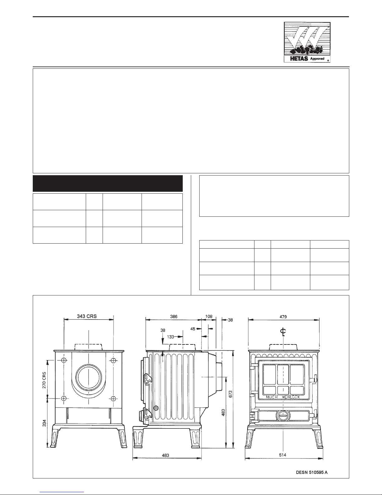
THE MUCH
WENLOCK
RATING
Top Flue
Outlet
4.3
14,500
6.1
21,000
Direct Space Heating
kW
Btu/h
kW
Btu/h
Water Heating
Rear Flue
Outlet
3.9
13,500
7.3
25,000
WARNING
BOILER MODEL
UNDER NO CIRCUMSTANCES MUST THE
APPLIANCE BE FIRED DRY AS DAMAGE WILL OCCUR
Top Flue Rear Flue
Direct Space Heating
73.6
2600
67.9
2400
14.5
156.25
12.2
131.25
12.2
131.25
9.9
106.25
m
3
ft
3
m
3
ft
3
m
3
ft
3
Pipe and Radiator Surface
(no domestic hot water)
Radiator Surface
(with domestic hot water)
The recommended heating surface area is based on an
average heat emission of 0.5 kW/m
2
(160 Btu/h/ft2).
These figures are maxima and must not be exceeded.
A margin (about 10% or 1.4m
2
- 15ft2) is recommended.
The Much Wenlock Stove with Boiler is intended to
provide space heating and the heating of domestic hot
water and radiators has been approved by the HETAS LTD
Appliance Approval Scheme. The appliance and burning
rate are controlled by the manual adjustment setting of
the ashpit door spinwheel only.
1. A 140 litre capacity indirect hot water storage cylinder
of the double feed type, complying with BS 1566 Part
1: DF TYPE 8 should be lagged and fixed vertically as
near as possible to the stove.
The 28mm minimum diameter primary flow and return
pipes must not exceed 10m in length and pipes longer
than 5m must be lagged. Ensure that the flow pipe
rises continuously from the stove boiler to the cylinder
to ensure good gravity circulation. In combined
systems, the water draw-off pipes to the taps must be
dead-leg connections from the vent/expansion pipe.
2. One boiler flow connection (preferably that to the
cylinder), must have an open vent. The connection to
the boiler must be such that air cannot be trapped in
the boiler. Any pipe size reduction must be made on
the vertical pipe of the vented flow pipe.
The heating flow and return pipes may be 22mm and
should preferably be connected to opposite tappings
to each other on each side of the boiler.
3. All installations must be fitted with a drain tap at the
lowest point of the system.
4. It is recommended that a gravity heat leak radiator 0.9
- 1.4m2(10-15ft2) heating surface be included, or a
reverse acting cylinder thermostat to activate the
pump in the event of overheating.
5. Long reach male fittings will be required to make
pipework connection into the boiler.
For correct operation of the appliance, the height of the
chimney from its base should not be less than 5.5m and
terminate above the roof in accordance with current
Building Regulations Section J/1/2/3 and requirements as
outlined in BS 6461 Part 1 and BS 7566 Parts 1 to 4
should be observed.
The structural flue through the chimney should not be
less than 175mm diameter. Pargeted lined flues, 230mm
x 230mm must be in sound condition, and any internal
offsets should not be less than 60˚ to the horizontal.
Check that the flue exit is not obstructed or reduced in
size.
IMPORTANT: FAILURE TO OBSERVE THE
RECOMMENDED MINIMUM SIZE OR METHODS OF
FLUE CONNECTION MAY LEAD TO EMISSION INTO
THE ROOM AND REDUCED BURNING RATES.
Existing Chimney
The internal and external condition of the chimney should
be checked before the appliance is installed and
rectification made where necessary to prevent air leakage
or porosity.
The flue through the chimney should be formed with
175mm diameter minimum moisture and acid resistant
liners to BS 1181 or precast linings as specified in the
current Building Regulations and requirement in BS 6461
Part 1 and BS 7566 Parts 1 to 4 should be observed.
When repairing existing chimneys, it is recommended
that the Building Inspector be consulted before
commencement of work with particular attention to the
chimney height and its termination.
NOTE: THE CHIMNEY MUST BE SWEPT BEFORE
INSTALLATION.
Where the chimney is believed to have served an open
fire installation it is possible that the higher flue gas
temperature from a closed appliance may loosen
deposits that were previously firmly adhered, with the
consequent risk of flue blockage. It is therefore
recommended that the chimney be swept a second time
after one month of regular use.
New Chimney
The flue should not be less than 175mm diameter and its
soundness confirmed by smoke testing or consulting
HETAS LTD who will give advice on the test method.
Ensure the chimney liners are free of any internal
projections such as building jointing composition before
the appliance is installed.
Factory-made Insulated Chimneys
It is recommended that the internal face of the chimney,
be refractory lined and otherwise comply with BS 4543.
The recommended minimum diameter is 150mm and
chimney manufacturers should be consulted for further
advice.
HOT WATER SYSTEM
THE CHIMNEY
PERFORMANCE
2
Chimney Terminations
All chimney should terminate above roof level in
accordance with current Building Regulations Section
J/1/2/3 and as outlined in BS 6461 Part 1 and BS 7566
Parts 1 to 4.
However well designed, constructed and positioned, the
satisfactory performance of a flue can be adversely
affected by the downdraughts caused by adjacent tall
buildings and trees or even a nearby hills. These deflect
the wind, creating a zone of high pressure over the
terminal causing it to blow directly down the chimney
flue.
A suitable anti-downdraught terminals such as the
MARCONE will usually effectively combat low pressure
down-blow but no known cowl is likely to prevent
downdraught due to a high pressure zone.
NOTE: ADVISE THE USER TO ENSURE THE CHIMNEY
FLUES ARE THOROUGHLY SWEPT AT A MINIMUM OF
12 MONTHLY INTERVALS AFTER THE APPLIANCE IS
COMMISSIONED.
The appliance and recess, hearth and chimney flue
installation should be in accordance with the relevant
current recommendation of the British Codes of Practice
BS 8303 and BS 6461 Part 1 and BS 7566 Parts 1 to 4,
with the boiler and heating installation complying with BS
5449 Part 1.
The boiler section must also be installed in accordance
with the bye laws of the Local Water Undertaking,
Regulations for the Electrical Equipment of Buildings published by the Institute of Electrical Engineers, and any
relevant requirement of the Local Authority.
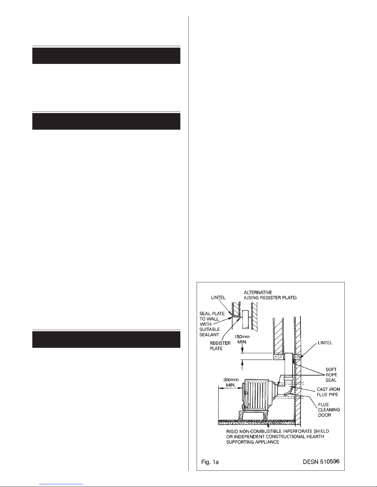
The appliance can be installed in a non-combustible
recess in which the hearth must be level and together
with the adjacent walls, conform to the current Building
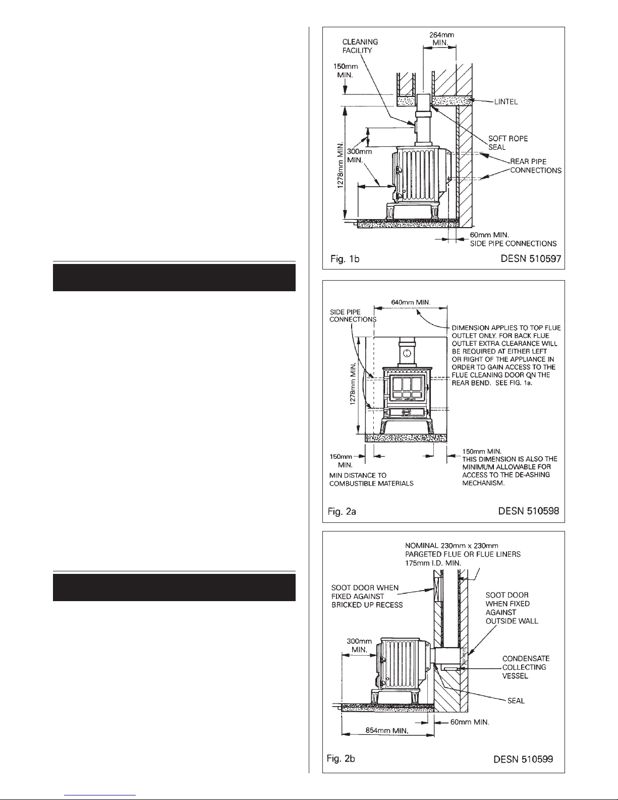
Regulations. See Figs. 1b and 2a.
A rectangular recess is required, not less than 640mm
wide, not less than 480mm deep from the face of the
recess and 1278mm minimum height for a top flue outlet
version. Holes will be required in one or both sides for the
pipework.
The clearance between the appliance and any
combustible material must be maintained as indicated in
Figs. 1a, 1b, 2a, 2b and 3.
A permanent unobstructed air vent is required having a
minimum effective area of 60cm
2
and communicating
directly to outside air or an adjacent room which itself has
a permanent air vent direct to outside air.
Air Extract Fans
Building Regulations 1990 permit the installation of an air
extract fan in a room containing a solid fuel appliance. The
appliance must be able to operate effectively whether or
not the fan is running. To this end:
1. Ensure the fan duty is capable of coping with the
respective room volume. Avoid an oversize fan duty
performance.
2. Follow the directions recommended by the fan
manufacturer on the necessary air ingress needed for
3
PREPARATION OF
BUILDERS RECESS OPENING
AIR SUPPLY
 Loading...