

Coalbrookdale GS1i Installation And Servicing Instructions

WARNING
This information is a copy of an original
archive, therefore Aga cannot be held
responsible for its continued accuracy.
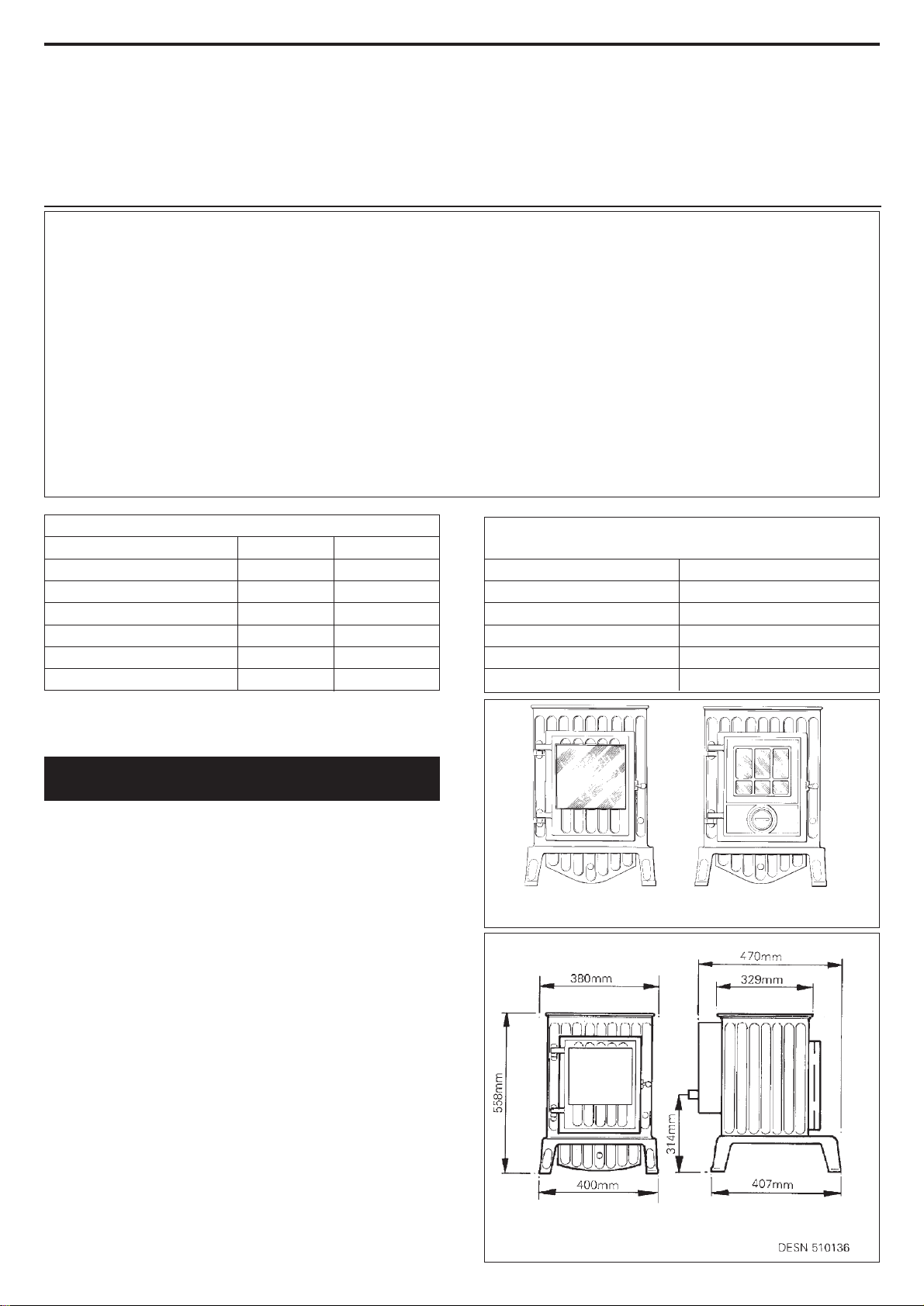
Gas Connection 8mm OD Tubing
Ignition - Piezo Spark Generator
Appliance Weight 63.5 kg
The Coalbrookdale GS1i is factory set to operate on
natural gas or propane (See data label) and is available
with a standard or traditional door option.
Due to newness the stove may give off a slight smell for
a short period after commissioning. This is quite normal
and will disappear after a few hours operation, open
windows and doors if required.
The Coalbrookdale GS1i has one access door as part of its
design. The glass fronted door is for access to the coals
and apart from initial commissioning of the stove, or in
case the pilot is required to be lit with a taper due to
malfunction of the spark ignition system. UNDER NO
CIRCUMSTANCES MUST THE STOVE BE OPERATED
WITH THIS DOOR OPEN OR IF THE GLASS IS CRACKED
OR BROKEN.
The Coalbrookdale GS1i has been designed similar to a
solid fuel stove to relevant safety standards, but during
use, many parts of the appliance can become HOT to
touch. We recommend that you provide and secure a
fireguard complying with BS 6539 when the room is used
by elderly, infirm or young persons.
Note: The illustrations show the appliance fitted with the
standard door option.
8/00 EINS 510878
Installation
and
Servicing
Instructions
Closure Plate Model
Consumer Protection Act 1987
As manufacturers and suppliers of cooking and heating products, in
compliance with Section 10 of the Consumer Protection Act 1987,
we take every care to ensure, as far as is reasonably practicable, that
these products are so designed and constructed as to meet the
general safety requirement when properly used and installed. To this
end, our products are thoroughly tested and examined before
despatch.
IMPORTANT NOTICE: Any alteration that is not approved by Aga-Rayburn,
could invalidate the approval of the appliance, operation of the warranty and
could also affect your statutory rights.
Control of Substances - Health and Safety
Important
This appliance may contain some of the materials that are indicated.
It is the Users/Installers responsibility to ensure that the necessary
personal protective clothing is worn when
handling, where applicable, the pertinent parts that contain any of
the listed materials that could be interpreted as being injurious to
health and safety, see below for information.
Firebricks, Fuel beds, Artificial Fuels - when handling use
disposable gloves.
Fire Cement - when handling use disposable gloves.
Glues and Sealants - exercise caution - if these are still in liquid
form use face mask and disposable gloves.
Glass Yarn, Mineral Wool, Insulation Pads, Ceramic Fibre,
Kerosene Oil - may be harmful if inhaled, may be irritating to skin,
eyes nose and throat. When handling avoid inhaling and contact with
skin or eyes. Use disposable gloves , face-masks and eye protection.
After handling wash hands and other exposed parts. When disposing
of the product, reduce dust with water spray, ensure that parts are
securely wrapped.
THE COALBROOKDALE GS1i
INTRODUCTION
GAS DATA
NAT GAS PROPANE
kWkW
7.0
6.
3.413.95
kW kW
3.35 3.35
1.871.87
MAX
HEAT INPUT (GROSS)
HEAT OUTPUT (GROSS)
MIN
HEAT INPUT (GROSS)
HEAT OUTPUT (GROSS)
SETTING PRESSURE (COLD)
NATURAL PROPANE
MAX
mbar
36.0 ± 1
MAX
mbar
17.7 ± 1
Burner Injector Nat-Cat 82-420
Burner Injector Propane Cat 92-190
Pilot Injector Propane-LPG 9206Pilot Injector Nat-NG 9008
DESN 510141 ‘A’ DESN 510274 ‘B’
STANDARD DOOR TRADITIONAL DOOR
OPTION OPTION
The installation of the appliance must be in accordance
with the relevant requirements of the Gas Safety
(Installation and Use) Regulations 1984 (as amended),
Building Regulations and the Building Standards
(Scotland) (Consolidation) Regulations. It should be in
accordance also with any relevant requirements of the
local Gas Region and Local Authority, and the relevant
recommendations of the following current British Codes
of Practice & Standards:
BS. 6891: Installation of pipes and meters. Low pressure
installation pipes.
BS. 5440: Parts 1 Flues & Part 2 Air Supply
BS. 5871: Part 1 Installation of Gas Fires. Convector
Heaters, Fire/Back Boilers.
BS. 6461: Codes of Practice for factory-made insulated
chimneys for internal application.
BS. 8303: Solid fuel appliance flue system.
In your own interests and that of safety to comply with
the law all gas appliances should be installed by
competent persons (Corgi Registered) in accordance with
the above regulations and with these instructions. Failure
to install the appliance correctly could lead to prosecution.
To ensure adequate circulation of convected air it is
recommended that the stove should not be installed into
a recess of a depth any greater than 300mm.
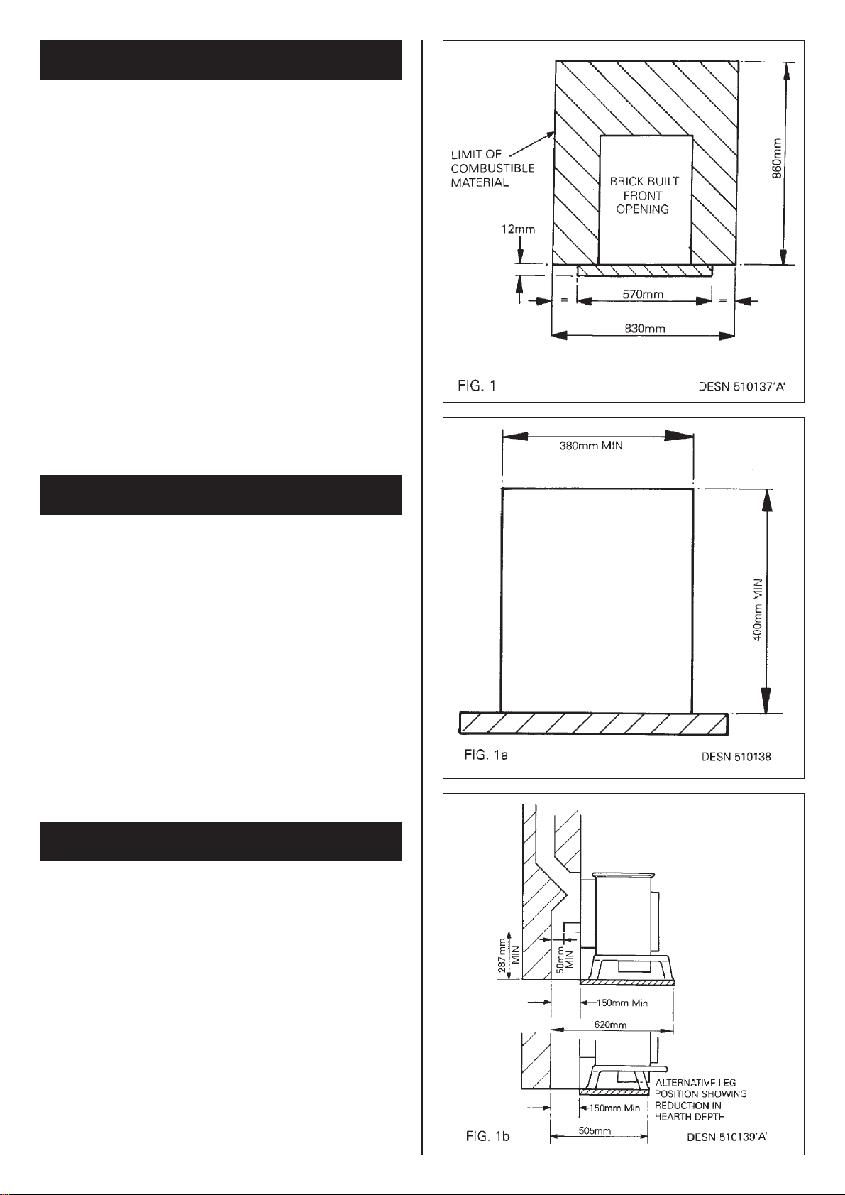
The appliance must be installed on a base of
incombustible material, at least 12mm thick, extending to
at least the front of the stove supporting legs or level with
the supporting front legs when fitted in their alternative
position, and to 85mm beyond each side of the stove
(570mm). See fig. 1, 1a and 1b.
The hearth must be capable of withstanding a maximum
temperature of 150˚C. Conglomerate marble, marble and
tiled surrounds can meet this requirement.
Combustible material must be cleared from the area
shown in fig. 1.
If any opening larger than that shown in fig. 1a is to be
used, the opening size must be reduced using non
combustible material to bring it within the limits required
for closure plate mounting. It must be at least 380mm
wide and 400mm in height.
There must be a minimum distance of 215mm between
the sides of the stove and any combustible material.
INSTALLATION INSTRUCTIONS
THE LOCATION
REMOVAL OF COMBUSTIBLE
MATERIAL
2

The stove may be connected to an existing masonry
chimney with a cross sectional dimension not less than
175mm.
or a lined masonry chimney to BS.6461 Part 1.
or a pre-cast flue block chimney to BS,1289 or BS.6461 or
chimneys which have been approved to the relevant
British Standards as being suitable for use with solid fuel
appliances.
or factory made systems which have been approved by
an accredited test house as being suitable for use with
appliances covered in BS.5871 Part 1.
Alternative detailed recommendations for fluing are given
in the current issue BS.5440 Part 1 which also covers
relevant details for termination.
The following notes are intended to give general
guidance:
The chimney must have a minimum effective vertical
height of 3 metres from the floor.
Clearance for shelves: A wooden shelf may be fitted
above the stove. The underside of the combustible shelf
above the top of the fire should be dimensioned
accordingly.
Depth of shelf Height to underside of shelf
150mm 558mm
175mm 575mm
200mm 600mm
225mm 650mm
250mm 700mm
275mm 750mm
300mm 800mm
If a brick chimney is to be used it MUST be swept prior
to installation.
Before installing the stove, or inserting a liner, check that
the flue is sound, free from obstruction and clean. If a
register plate, restrictive plate, or damper etc is fitted in
the flue, it MUST be removed or locked fully open.
If the stove is to be fitted in a fireplace in which the air
supply enters below floor level this supply must be sealed
off.
The catchment space and opening size must not be less
than the dimensions in figs 1a/1b. The flue spigot must
pass through the closure plate by at least 20mm and
must have a minimum dimension of 50mm from its open
end to any obstruction.
Under no circumstances must a flue spigot extension
be fitted.
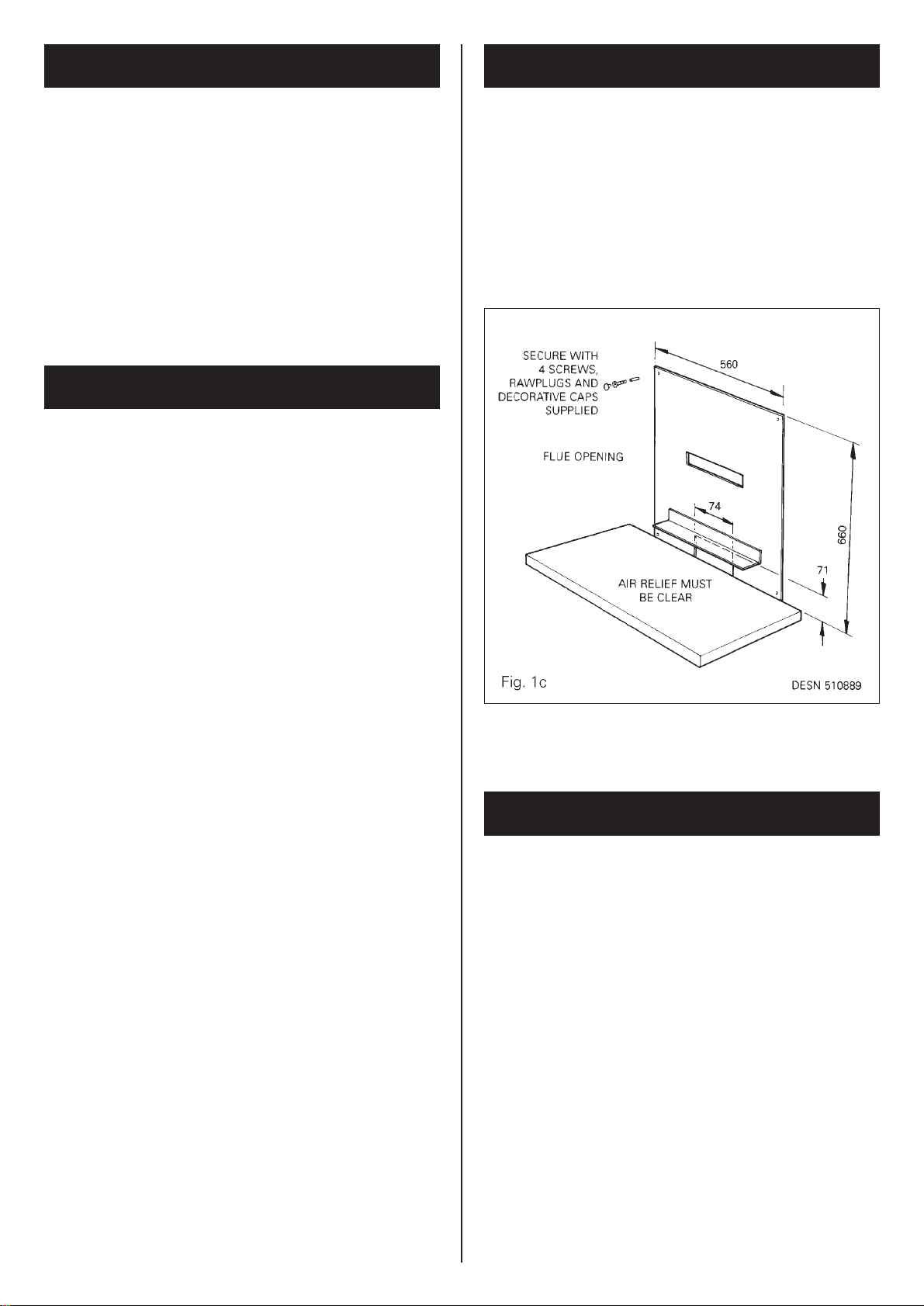
Ensure that the air relief opening at the bottom edge of
the closure plate is completely clear.
The stove does not normally require any additional
purpose made ventilation.
If there is any type of extraction fan fitted in the same
room as the stove, there is a possibility that if adequate
air inlet area from outside is not provided, spillage of the
products from the appliance flue could occur when the
extractor fan is in operation. Where such installations
occur, a spillage test as detailed in BS.5440: Part 1 must
be carried out.
3
THE FLUE - See fig 1a/1b AIR SUPPLY
EFFECT OF EXTRACTION FAN
The complete installation must be tested for soundness
and purged as described in BS. 6891.
The gas inlet to the stove is 8mm dia compression, and
providing the distance from the service cock to the stove
does not exceed 1.5m, 8mm dia rigid or semi-rigid supply
pipe may be used.
Above this length, 15mm dia rigid or semi-rigid pipe
should be used.
A service cock must be fitted adjacent to this appliance.
Unpacking
Remove all parts from inside the pack and ensure that no
damage has occurred during delivery transit. If so, please
contact your local stockist.
Items in Pack:
Instructions-Installation/Servicing and Operating
Coal Guard
Small Coals (9)
Large Coals (14)
Control Cover
Door Locking Tool
Clay Aggregate
Closure Plate
Fixing Screws and Rawlplugs
Proceed to assemble the stove as follows:
If the reduced leg position is required. Gently lay the
stove on its side. Unscrew the front legs secured with
one screw. Refit in second hold further back with screw
previously removed.
The closure plate must always be fitted as in Fig. 1C with
the four rawlplugs, screws and decorative caps supplied.
Adhesive tape or other sealing material which is suitable
for the type of surface may be used. (The closure plate
supplied with the stove may be cut, on site, to the correct
size depending upon the size of the fireplace opening).
Locate the stove so that the flue spigot protrudes at least
20mm into the chimney cavity.
Position the appliance in accordance with the instruction
given in the section ‘LOCATION’ and connect the flue
pipe in accordance with the section ‘THE FLUE’.
FLEXIBLE PIPE/CONNECTIONS MUST NOT BE USED.
Connect the stove to the gas supply. (See Gas
Connection).
4
GAS CONNECTION
APPLIANCE ASSEMBLY
CLOSURE PLATE
INSTALLING THE APPLIANCE

Open the door of the stove (Using the tool supplied). See
Fig. 2.
Pour the aggregate into the burner tray as illustrated in
Fig. 3.
Fit the coal guard as illustrated in Fig. 3.
Do not compress or tap down. Any excess should be
kept and handed to the user for future use.
Positioning the Coals
Carefully place the coals on the coal bed as illustrated in
Figs 4, 5, 6, 7 and 8.
Close the door and lock (Using the tool supplied).
WARNING: USE ONLY THE SIMULATED COALS
SUPPLIED WITH THE APPLIANCE TO BUILD THE BED.
UNDER NO CIRCUMSTANCES USE EXTRA COALS OR
PUT ANY OTHER MATERIAL ON THE FUEL BED.
DO NOT OPERATE THE STOVE WITH THE DOOR OPEN
OR IF THE GLASS IS CRACKED OR BROKEN.
Hands should be washed after handling coals. (If gloves
are not used).
5
LAYING THE FUEL BED
FIG. 2
 Loading...