

Page 1

CA386-N1
AESTHETICS, INC
Networked
Embedded PC
REFERENCE
MANUAL
VERSION 1.0
Page 2

Page 3

Page 4

CA386-N1
Reference Manual
Disclaimers
Coactive Aesthetics reserves the right to make changes without further notice to an y product herein to impro v e reliability,
function, or design. Coactive Aesthetics does not assume any liability arising out of the application or use of any product
or circuit described herein; neither does it convey any license under its patent rights nor the rights of others. Coactive
Aesthetics products are not authorized for use as components in life support devices or systems intended for surgical
implant into the body or intended to support or sustain wet life. Buyer agrees to notify Coactive Aesthetics of any such
intended end use whereupon Coactive Aesthetics shall determine availability and suitability of its product or products for
use intended.
Use, duplication, or disclosure by the United States Government is subject to restrictions as set forth in subparagraph (c)
(1) (ii) of the Rights in T echnical Data and Computer Software clause at CFR 52.227-7013. Coactiv e Aesthetics, Inc. 4000
Bridgeway Suite 303, Sausalito, CA 94965.
Trademarks
Motorola is a registered trademark of Motorola, Inc.
Intel is a registered trademark of Intel Corp.
UNIX is a registered trademark of American Telephone and Telegraph Co.
IBM is a registered trademark of International Business Machines, Inc.
MS-DOS is a registered trademark of Microsoft Corp.
Echelon, LON, LonWorks, LonBuilder, LonManager, LonTalk, LonUsers, NEURON, 3120, and 3150 are trademarks of
Echelon Corporation.
All other trademarks are the property of their respective owners.
Copyrights
Copyright (c) 1994-1995 by Coactive Aesthetics.
All rights reserved.
Page 5

Manual Revision 4
Covers:
CA386-N1 Hardware, Revision C
Programming the CA386-N1, Version 1.0
Coactive Aesthetics
4000 Bridgeway, Suite 303
Sausalito, CA 94965
(415) 289-1722
(415) 289-1320 (FAX)
[email protected] (Email)
http://www.coactive.com (WWW)
Page 6

Page 7

Tab le of Contents
Chapter 1 Hardware
1.1 Introduction 1
1.2 Specifications 2
1.3 Related Documentation 2
1.4 Power 2
1.5 Connectors and Jumpers 3
1.5.1 Overview 3
1.5.2 Flash Loader Start-up (JP1) 5
1.5.3 i386EX Reset Generation Jumper (JP2) 5
1.5.4 SMI Source Selection Jumper (JP3) 5
1.5.5 NMI Signal Generation Jumper (JP4) 5
1.5.6 DMA Channel Selection for PC/104 Bus (JP5, JP6) 5
1.5.7 Memory Size Configuration Jumpers (JP7, JP8) 6
1.5.8 User Definable Input Jumper/Switch (JP9) 6
1.5.9 RS-485 Option Jumper (JP10) 7
1.5.10 Asynchronous Serial Communications: COM1, COM2 (J1, J2, J5) 7
1.5.11 PC/104 Bus (J3, J4) 9
1.5.12 I/O Ports (J6) 9
1.5.13 Power Connectors (J7, J10) 11
1.5.14 Serial Peripheral Interface (SPI) (J8) 11
1.5.15 SIMM Memory Socket (U9) 12
1.6 Parts Listing 12
1.7 Mechanical Information 15
Chapter 2 DOS Programming
2.1 Introduction 1
2.2 Quick Start 1
2.3 Desktop Development 3
2.4 Memory Map 7
Table of Contents
2.1.1 Related Documents 1
2.2.1 Overview 1
2.2.2 Tools 2
2.2.3 QuickStart Steps 2
2.3.1 CA386-N1 Companion Diskette 4
2.3.2 The RAM Disk 4
2.3.3 Development using the Remote Serial Disk 4
2.3.4 Development under DOS 5
Page 8

Table of Contents
2.5 Peripheral I/O 8
2.6 Flash Loader 9
2.6.1 General 9
2.6.2 Addresses 9
2.6.3 Memory Map 10
2.6.4 Downloading a .HEX File to Flash 10
2.6.5 Help Command 11
2.6.6 “:<.....>” (Hex Record) 11
2.6.7 “m <A1> <A2>” (Address Remapping) 11
2.6.8 “w <A1> <A2>” (Address Window) 11
2.6.9 “e <A> [L]” (Erase Sectors) 12
2.6.10 “d <A> [L]” (Display Memory) 12
2.6.11 “j [A]” (Set Jump Address) 12
2.6.12 “b <n>” (Set Baud Rate) 12
2.6.13 “a <n>” (Auto Erase) 12
2.6.14 “v <n>” (Verify Mode) 12
2.6.15 “s” (Show Status) 13
2.6.16 “r” (Reboot) 13
2.7 Flash Disk Organization and Programming 13
2.7.1 ROM Disks 14
2.8 Peripherals 14
2.8.1 Serial Ports 15
2.9 Troubleshooting 15
2.9.1 Communicating with the CA386-N1 15
Appendix A CA386-N1 Schematic
Appendix B PC/104 Specification
CA386-N1 REFERENCE MANUAL
Page 9
Chapter 1 Hardware
1
1
1.1 Introduction
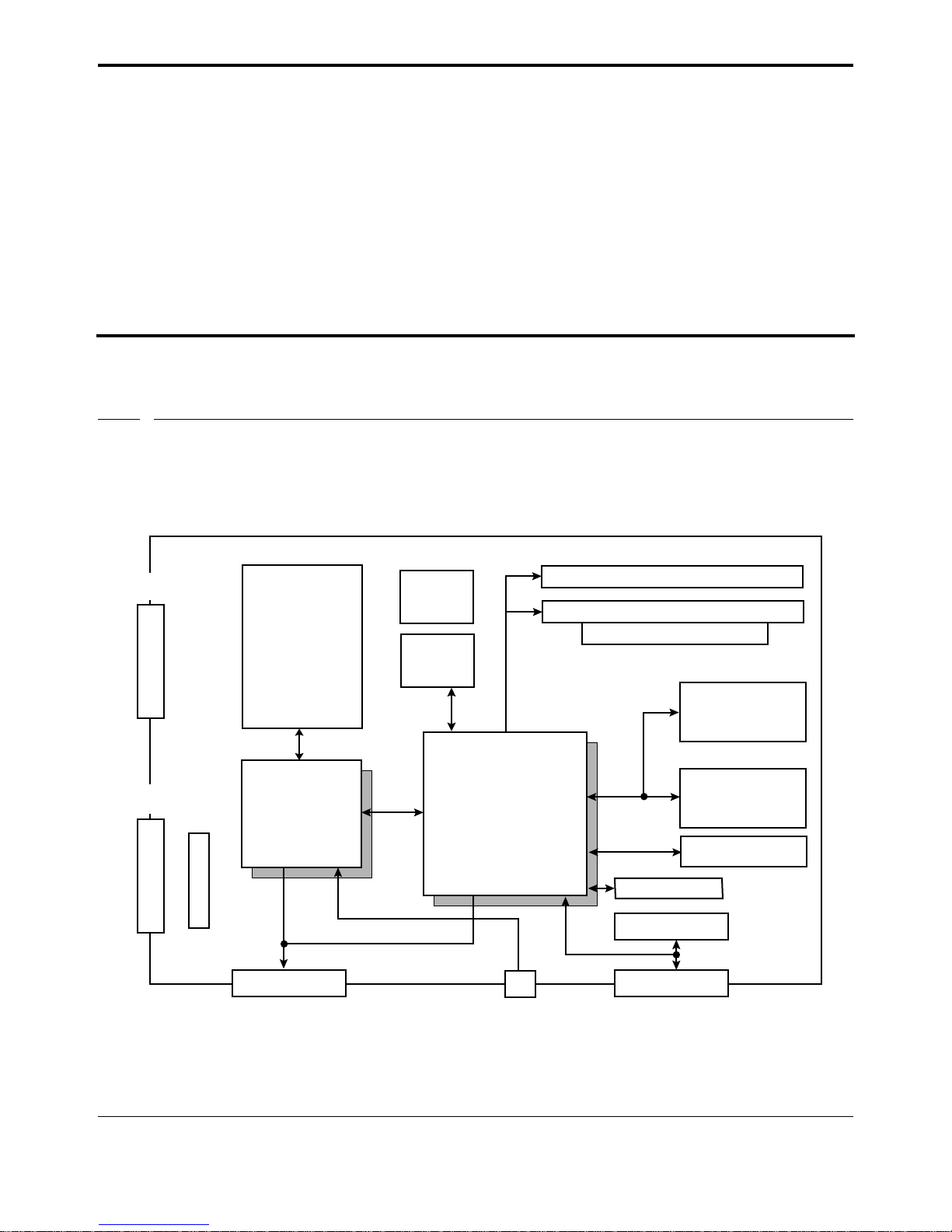
This chapter describes the CA386-N1 hardware. It lists specifications for I/O, power, and mechanical dimensions, covers communications issues, and describes all the jumpers and connectors and their pin-outs. A schematic and a parts list are also included at the end of the chapter. Figure 1.1 is a simplified block diagram of the
CA386-N1.
NETWORK
CONNECTOR
POWER
CONNECTOR
3.0V
CLOCK
78kB or 1.2MB
TWISTED
PAIR
TRANSCEIVER
NEURON
3120
PROCESSOR
INTERNAL PWR
STATUS LEDs NETWORK
BATTERY
OPTIONAL
REAL-TIME
CLOCK
i386EX
MICROCONTROLLER
I/O CONNECTOR
8/16-BIT PC/104
CONNECTOR
256K to 4MB RAM
512K FLASH EPROM
Application
Input Jumper
SPI INTERFACE
RS-232 (COM2)
RS-232 (COM1)
SERVICE
PUSHBUTTON
FIGURE 1.1 CA386-N1 Block Diagram
Hardware 1-1
Page 10

Specifications
1.2 Specifications
The CA386-N1 is an Intel i386EX based single-board computer with integrated LonTalk interface. Hardware
specifications are as follows:
• 25MHz Intel i386EX Processor
• 256K, 1M, or 4M SIMM DRAM
• 512K Flash EPROM
• NEURON 3120 with MIP Firmware installed
• LonTalk Transceiver: TPT/XF-78, TPT/XF-1250, or FTT-10
• 2 RS-232 asynchronous serial ports (COM1, COM2)
• RS485 option on COM1
• 8 TTL-level digital I/O
• 3 programmable counter/timers
• Battery-backed real-time clock (optional)
• 8/16-bit PC/104 Bus
• Power Requirements: single +5 volt operation (+12V, -12V required if certain PC/104 peripherals are
used)
• Power Consumption: nominal 500mA@5VDC
• Power Connector: 5-wire 5.08mm removable-plug screw terminal
• Network Connector: 2-wire 5.08mm removable-plug screw terminal or dual RJ45 jacks
• Dimensions: 4” (10.2mm) x6.25”(15.9mm) x approximately 1/2”
• Operating Temperature: 0-70 C
1.3 Related Documentation
The following documents are useful for a full understanding of the CA386-N1 system:
• Intel386EX Embedded Microprocessor Hardware Reference - available from Intel Corporation Liter-
ature Sales, P.O. Box 7641, Mt. Prospect, IL 60056-7641
• LONWorks Technology Device Data - available from Motorola Literature Distribution Center, P.O.
Box 20912, Phoenix, AZ 85036
1.4 Power
Power is supplied to the CA386-N1 through either connector J7 or J10. There are lines on both J7 and J10 for the
following voltages:
• +5VDC
• +12VDC
• -12VDC
• Gnd
• Vin - Variable Voltage Input for use with a power supply or converter
1-2 CA386-N1 REFERENCE MANUAL
Page 11

The board is designed to be powered in one of two ways:
• “Raw” power and ground connected through J7-Vin, and a regulator attached to J10 which takes the
raw power in and produces +5V (and +12V, -12V if required).
• +5V (and +12V, -12V if required) supplied through J7; J10 unused.
The first method is useful for providing an internal power supply or converter in an enclosure.
1.5 Connectors and Jumpers
1.5.1 Overview
Figure 1.2 shows the locations of all the connectors and jumpers on the CA386-N1. The following sections
describe each jumper and connector in detail. Note that each connector or jumper shown below is oriented such
that the power and network connectors (J7, J9) are at the “top” of the board. Also note that the reference designators (labels) are shown in their actual location and orientation relative to the connector or jumper.
Connectors and Jumpers
Hardware 1-3
Page 12

Connectors and Jumpers
C
JP10
FIGURE 1.2 CA386-N1 Parts Locations
1-4 CA386-N1 REFERENCE MANUAL
Page 13
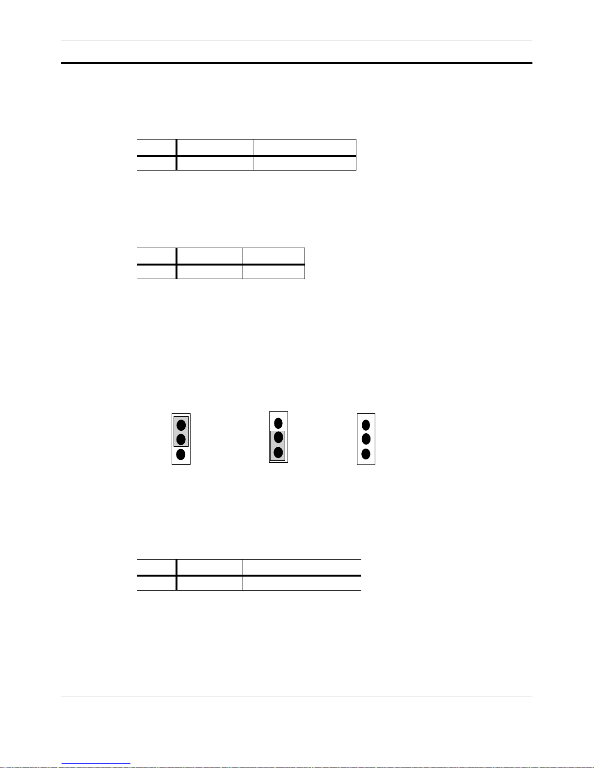
1.5.2 Flash Loader Start-up (JP1)
This input jumper, when shorted during power-up, causes the Flash loader to come up. The default is unshorted.
Jumper Run Flash Loader Run Application/OS
JP1 short open (default)
TABLE 1.1 JP1: Run Flash Loader
1.5.3 i386EX Reset Generation Jumper (JP2)
When shorted, this jumper will reset the i386EX CPU. The default is un-shorted.
Jumper Normal Run Reset 386EX
JP2 open (default) short
TABLE 1.2 JP2: 386EX Reset Generation
1.5.4 SMI Source Selection Jumper (JP3)
Connectors and Jumpers
JP3 allows selection of how the SMI signal is generated. The choices are (a) generation via software control
(using Digital I/O Port 2, Pin-7), (b) manual generation, and (c) no SMI generation.
Software control via
digital port 2, pin-7
1
JP3
FIGURE 1.3 JP3: SMI Source Selection
1.5.5 NMI Signal Generation Jumper (JP4)
Shorting JP4 produces the NMI signal for the i386EX CPU. The default position of this jumper is open.
Jumper No NMI signal Generate NMI signal
JP4 open (default) short
TABLE 1.3 JP4: NMI Signal Generation Jumper
Manual SMI
generation
1
JP3
(default)
1
JP3
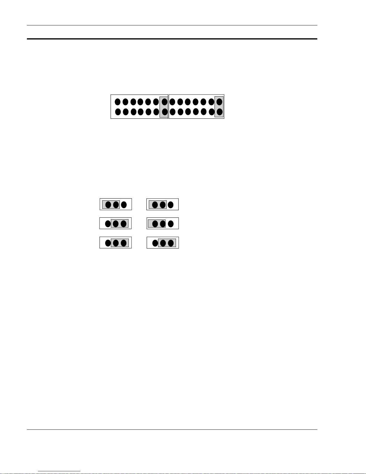
1.5.6 DMA Channel Selection for PC/104 Bus (JP5, JP6)
The PC/104 Bus supports 8 DMA channels, but the CA386-N1 can only support one of these eight. The JP5 and
JP6 jumper blocks determine which of the eight DMA channels on the PC/104 bus is selected.
Hardware 1-5
Page 14
Connectors and Jumpers
DRQ0
DRQ1
DRQ7
o o o o
JP6
DACK7
1
(default positions shown)
FIGURE 1.4 JP5, JP6: PC/104 DMA Channel Selection Jumpers
1.5.7 Memory Size Configuration Jumpers (JP7, JP8)
Jumpers JP7 and JP8 control the configuration of DRAM memory on the CA386-N1. The sizes supported are:
256KB, 1MB, and 4MB.
o o o o
DACK0
DACK1
1
JP5
JP8
JP7
1 1
JP8
JP8
JP7
JP7
1
FIGURE 1.5 JP7, JP8: Memory Size Configuration Jumpers
1.5.8 User Definable Input Jumper/Switch (JP9)
JP9 is an optional jumper/switch which may be used as an application specific configuration input; for example
JP9 may be used to define a hardware-level network address. By def ault this jumper is unconnected and not used.
1 1
1
4MB
1Mb
256KB
1-6 CA386-N1 REFERENCE MANUAL
Page 15
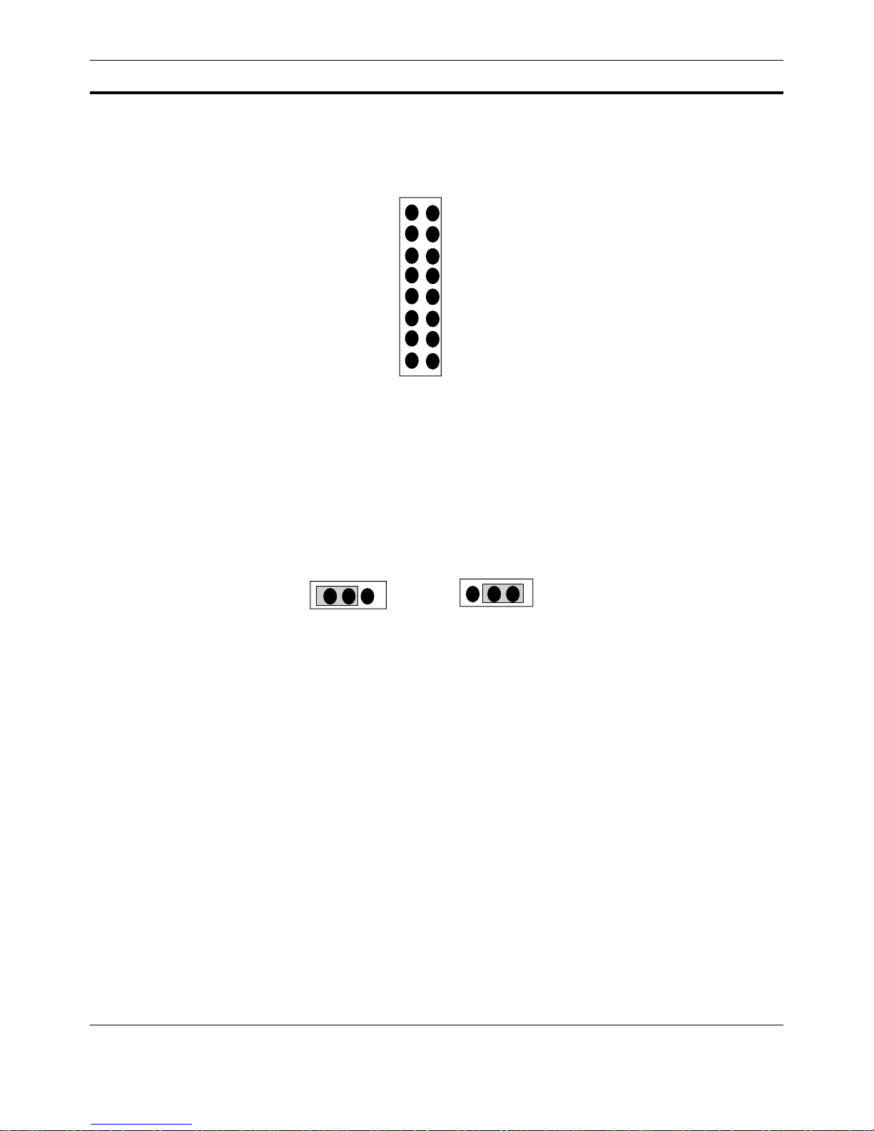
Connectors and Jumpers
JP9
1
FIGURE 1.6 JP9: User-Definable Input Jumper/Switch (I/O address 38Eh)
1.5.9 RS-485 Option Jumper (JP10)
JP10 is a jumper which configures COM1 as RS-232 (J5) or RS-485 (J1). NOTE: The RS-485 option is not
available on all revisions of the CA386-N1, including revision B. JP10 is not present on revision B, and
COM1 is available on both J5 and J1 as RS-232.
1
DI0
DI1
DI2
DI3
DI6
DI7
JP10
DI4
DI5
GND
GND
GND
GND
GND
GND
GND
GND
JP10
1
RS-232
RS-485
(Default)
FIGURE 1.7 JP10: RS-485 Option Jumper
1.5.10 Asynchronous Serial Communications: COM1, COM2 (J1, J2, J5)
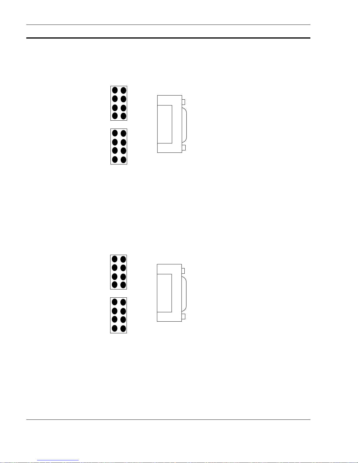
The CA386-N1 has two serial ports: 1 RS232 and 1 RS232 or RS485. One is connected to a female DB9 connector (J5). Both are accessible via header connectors (J1, J2). J1 and J2 are designed to connect directly via a 10pin ribbon-cable to a DB9 connector. Figure 1.8 shows the pin-outs for these connectors with COM1 configured
for RS232.
Hardware 1-7
Page 16
Connectors and Jumpers
(UNUSED)
Tx
Rx
GND
(COM1)
1
1
(COM2)
J5
J1
1
J2
Female DB9
Connector
DB9 Connections
2 - Tx
3 - Rx
5 - GND
(COM1)
FIGURE 1.8 J1, J2, J5: RS-232 Communications
Figure 1.8 shows the pin-out for COM1(J1) when configured as RS-485.
(COM1)
Rx_high
Rx_low
Tx_low
Tx_high
Tx
Rx
1
J1
1
J2
J5
1
(UNUSED)
GND
(COM2)
FIGURE 1.9 J1, J2, J5: RS-232 and RS-485 Communications
1-8 CA386-N1 REFERENCE MANUAL
Female DB9
Connector
Page 17
1.5.11 PC/104 Bus (J3, J4)
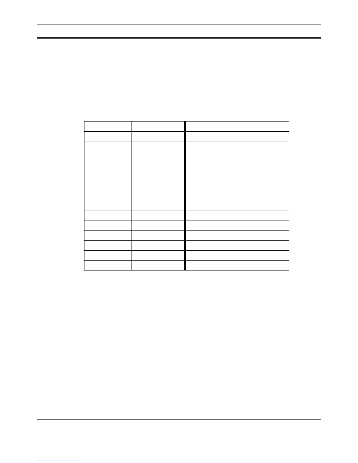
Connectors J4 and J3 provide the 8 and 16-bit PC/104 connections respectively. See the PC/104 Bus Specification for full information on the PC/104 bus signals.
Table 1.4 shows the complete mapping between the CA386-N1 and PC/104 IRQ signals. Note that some of these
mappings are different for Rev C and Rev B of the CA386-N1 (shown in bold in the table).
CA386-1 Rev C PC/104 CA386-N1 Rev B PC/104
IRQ-7 IRQ-7 IRQ-7 IRQ-5
IRQ-6 IRQ-6 IRQ-6 IRQ-6
IRQ-5 IRQ-5 IRQ-5 IRQ-7
IRQ-9 IRQ-9 IRQ-1 IRQ-9
IRQ-14 IRQ-14 IRQ-9 IRQ-14
N/C IRQ-3 N/C IRQ-3
N/C IRQ-4 N/C IRQ-4
N/C IRQ-10 N/C IRQ-10
N/C IRQ-11 N/C IRQ-11
N/C IRQ-12 N/C IRQ-12
N/C IRQ-15 N/C IRQ-15
IRQ-1 N/C IRQ-14 N/C
IRQ-13 N/C IRQ-13 N/C
IRQ-8 N/C IRQ-8 N/C
Connectors and Jumpers
TABLE 1.4 IRQ Mappings
1.5.12 I/O Ports (J6)
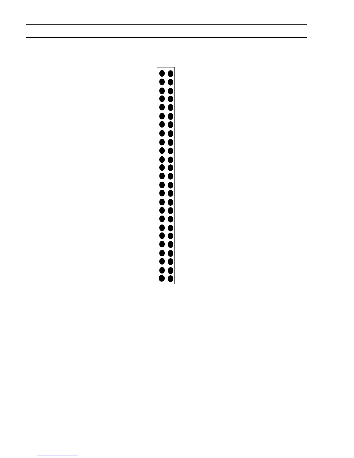
The built-in I/O ports of the i386EX processor are available on connector J6. This is a 50-pin header connector
compatible with many industry-standard I/0 racks. The I/O signals from this connector are all TTL level.
Figure 1.10 shows the signals on connector J6. Sample I/O racks that can be interfaced to J6 include:
• Dataforth(1-800-444-7644) Part# SCMD-PB8
• IOMation (617-255-8100 / 617-255-8181 (FAX)) Part# DB-16
• OPTO-22 (909-695-9299 / 909-695-2712 (FAX)) Part# PB8H, PB16H
Hardware 1-9
Page 18
Connectors and Jumpers
+5V DC
N/C
N/C
N/C
N/C
N/C
N/C
Timer Gate 2
Timer Clk 2
Timer Out 2
Timer Gate 1
Timer Clk 1
Timer Out 1
N/C
Timer Clk 0
Timer Out 0
DIO7 (Port 1, Pin 7)
DIO6 (Port 1, Pin 6)
DIO5 (Port 1, Pin 5)
DIO4 (Port 1, Pin 4)
DIO3 (Port 1, Pin 3)
DIO2 (Port 1, Pin 2)
DIO1 (Port 1, Pin 1)
DIO0 (Port 1, Pin 0)
+5V DC
1
GND
GND
GND
GND
GND
GND
GND
GND
GND
GND
GND
GND
GND
GND
GND
GND
GND
GND
GND
GND
GND
GND
GND
GND
GND
FIGURE 1.10 J6: Multipurpose Digital I/O Port
1-10 CA386-N1 REFERENCE MANUAL
J6
Page 19
1.5.13 Power Connectors (J7, J10)
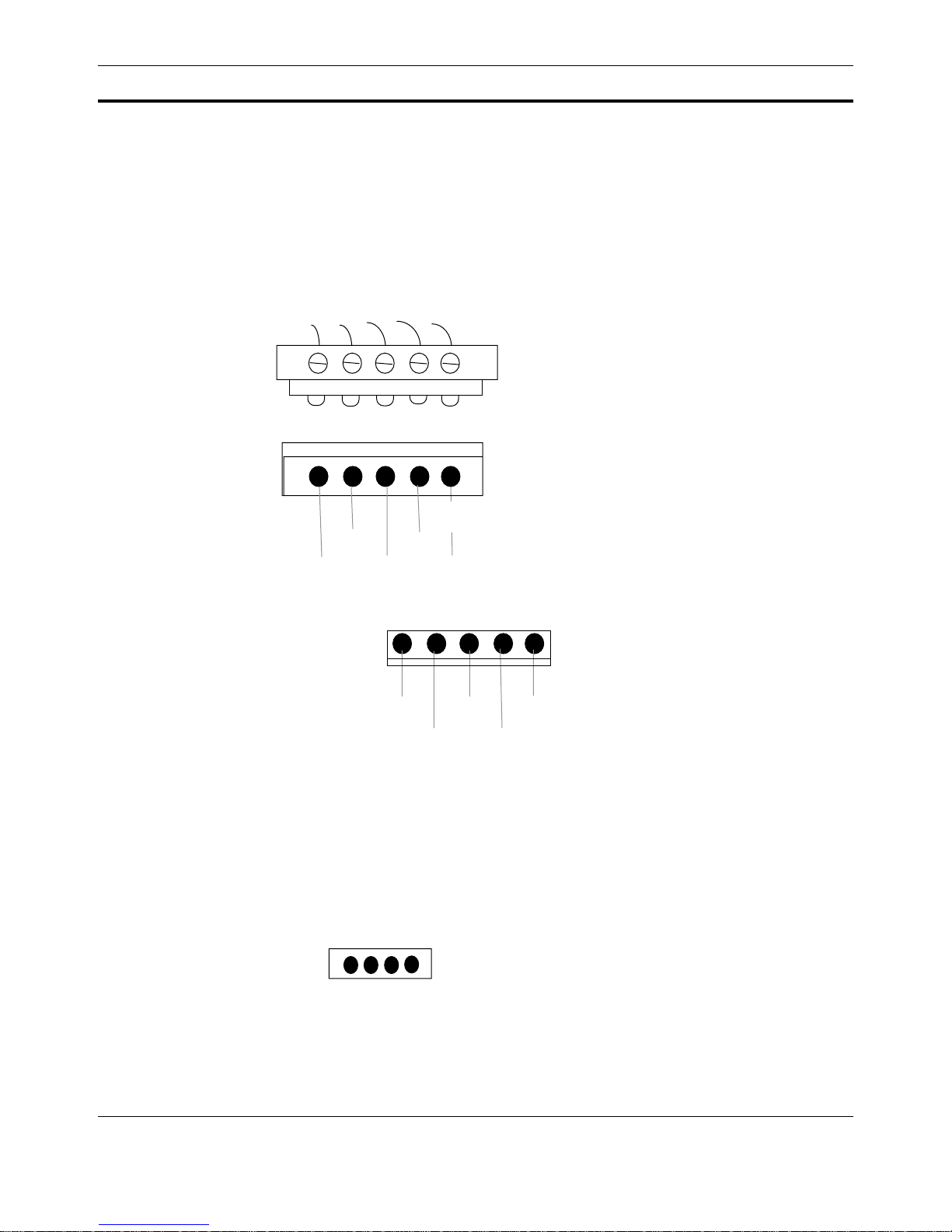
Figure 1.11 shows the J7 and J10 power connectors. J7 is a Weidmuller 5.08mm removable screw terminal connector. J10 is a .15” 5-pin header connector. See Section 1.4, Power for a description of the use of these signals.
Connectors and Jumpers
5.08mm removable
screw terminal
J7
+12V
-12V
+5V
J10
1
FIGURE 1.11 J7, J10: Power Connectors
1.5.14 Serial Peripheral Interface (SPI) (J8)
The SPI port of the i386EX is available through connector J8.
1
1
Gnd
Vin
+5V
Gnd +12V
J8
-12VVin
SPI
Pin-1: STXCLK
Pin-2: SRXCLK
Pin-3: SSIOTX
PIN-4: SSIORX
FIGURE 1.12 J8: SPI Port
Hardware 1-11
Page 20
Parts Listing
1.5.15 SIMM Memory Socket (U9)
Socket U9 accepts standard 30-pin SIMM memory modules. Sizes supported are:
• 256KByte
• 1MByte
• 4MByte
The recommended minimum speed for memory is 80nS. Either 8- or 9-bit SIMMs are acceptable. See
Section 1.5.7, Memory Size Configuration Jumpers (JP7, JP8) for details on configuring the controller
for different memory sizes.
1.6 Parts Listing
Reference Designation Description
PASSIVES **************************
C37, C38 18 pF @ 100V monolithic
C31 220 pF cap
C44, C45 1000 pF cap
C46 1000 pF @2KV (U16 Option Only)
C1-10, C12-18, C25-
30, C32-36, C39-43,
C47
C11 10uF Electrolytic,16V
C19-24, C48, C49 22 uF Electrolytic, 35V
R1, R2, R11 33 Ohm resistor
R23 270 Ohm resistor
R8, R9, R12 330 Ohm resistor
R3-R7, R10, R13-14,
R19, R21, R24-30, R32
R31 47K Ohm resistor
Y1 10 MHz XTAL
X2 14.318 MHz XTAL
X1 50 MHz Oscillator
R18 4 x 33 Array Resistor Network
R16, R17 5 x 33 Array Resistor Network
R20 9 x 10K Buss Resistor Network
R15 7 x 10K Buss Resistor Network
R22 5 x 470 Buss Resistor Network
D6, D7, D8 4 x 1N4148 Diode Array
0.1uF Bypass Caps
10K Ohm resistor
TABLE 1.5 CA386-N1 Parts List
1-12 CA386-N1 REFERENCE MANUAL
Page 21
Reference Designation Description
D1, D2 Battery Diode
D3 LED (Yellow)
D4 LED (Red)
D5 LED (Green)
BT1 3.0V Battery
MECHANICAL ***************************
J9 Network Conn. (5.08 mm screw Terminals)
J9-Mate Male mate for J9
J9A, J9B Alternate Network Conn. (RJ45)
JP1, JP2, JP4 1x2 pin .1” jumper header
JP7, JP8, JP3 1x3 .1” jumper header
JP5, JP6 7x2 .1” jumper header
JP9 8x2 .1” jumper header
JP10 1x3 .1” jumper header
S2 Momentary push-button
S1 16 pin address DIP switch
S1-ALT 8x2 .1” jumper header
J3 8-bit PC/104 Connector (2x32 .1” Female
Socket)
J4 16-bit PC/104 Connector (2x20 .1” Female
Socket)
J6 25x2 .1” header
J1,J2 4x2 .1” header
J8 4x1 .1” header
J7 5.08mm Wiedmuller Screw Terminal
J7-Mate Mate for J7 connector
J10 1x5 .15” header
J5 Female DB9
SOCKETS ***************************
SU2 MACH120 Socket
Parts Listing
TABLE 1.5 CA386-N1 Parts List
Hardware 1-13
Page 22
Parts Listing
Reference Designation Description
SU9 30-pin SIMM socket
SU11 18-pin DIP socket
CPU ********************************
U15 MC143120FU (10MHz) NEURON CPU
U1 Intel i386EX_P CPU (25 MHz)
U11 Fox RTC-72423
TRANSCEIVERS ********************************
U14 TPT/XF-78 (78K TP LonTalk Transceiver) or
TP/XF-1250 (1.25M TP LonTalk Transceiver)
U16 FTT-10 (78K Free Topology LONTalk Trans-
ceiver)
U10 MAX233
MEMORY ********************************
U9 HB56A48A-8 (Hitachi) SIMM memory [or
equivalent]
U8 AM29F400-T120
LOGIC *********************************
U13 MC34064D-5
U2 MACH120
U12 74ACT244
U4 74ACT16245
U5,U6,U7 74ACT157
U3 74ACT14
TABLE 1.5 CA386-N1 Parts List
Notes:
1. U14 and U16 are mutually exclusive options
1-14 CA386-N1 REFERENCE MANUAL
Page 23
Mechanical Information
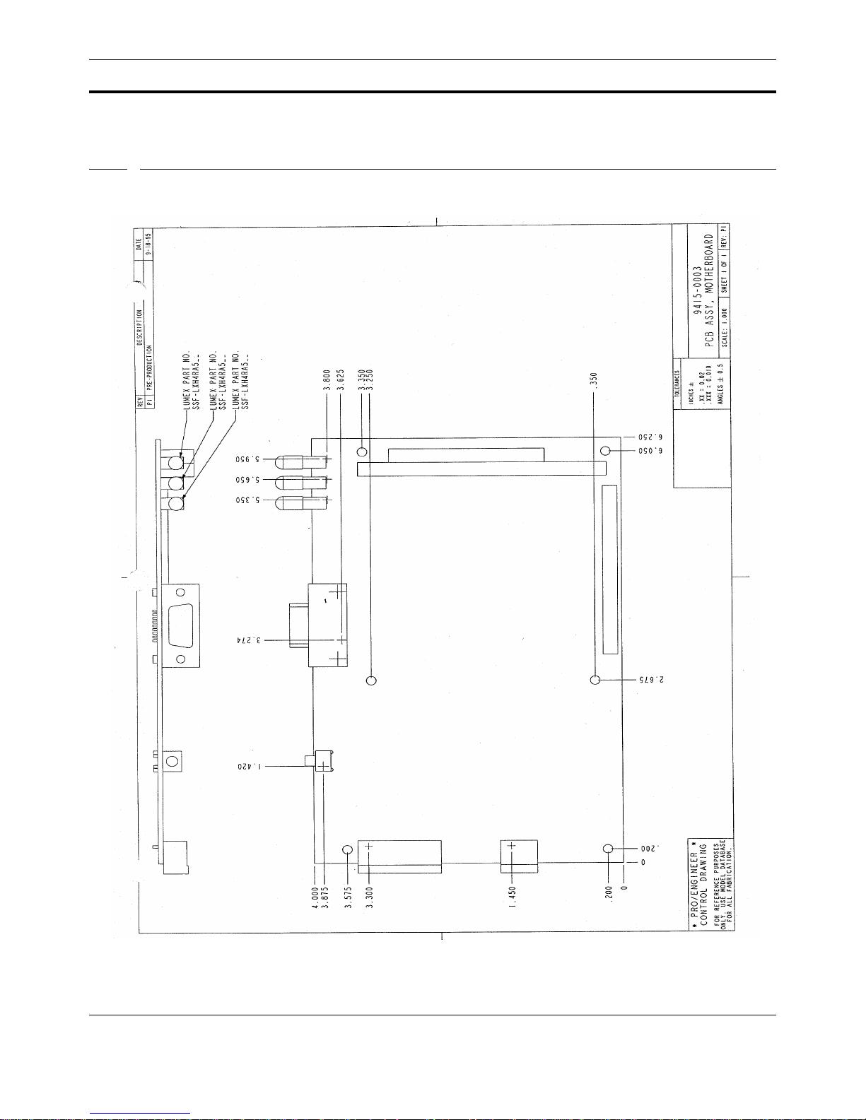
1.7 Mechanical Information
Figure 1.13 below shows the mechanical specifications for the CA386-N1. NOTE: LED parts may vary.
FIGURE 1.13 CA386-N1 Mechanical Specifications
Hardware 1-15
Page 24

Mechanical Information
1-16 CA386-N1 REFERENCE MANUAL
Page 25

Chapter 2 DOS Progr amming
2
2
2.1 Introduction
This chapter describes the programming features of the CA386-N1. A Quick Start section is included for compiling and running an application on the CA386-N1. This chapter also describes the Flash loader program, the procedure for programming Flash, and the DataLight ROM-DOS.
The CA386-N1 is normally shipped from the factory with the DataLight ROM-DOS O/S and Coactive’s Flash
loader program installed in the on-board Flash memory. The Flash loader program can be used to install new O/S
versions, applications, and file-systems into the Flash memory.
2.1.1 Related Documents
This document assumes that the reader is familiar with DOS and the general concepts of embedded systems (e.g.,
memory maps). For topics related to programming the CA386-N1, the reader is referred to the following documents:
• For PC/104: IEEE P996 Specification and P996.1 Standard for Compact Embedded PC Modules.
• Hosted Node SDK (HN-SDK) Reference Manual - Coactive Aesthetics, Inc.
2.2 Quick Start
This section provides a brief overview of programming the CA386-N1. Following the steps in this section, the
reader will be able to install the CA386-N1 Companion Diskette, compile a simple “hello world” application
under Microsoft C, and download and run it on the CA386-N1.
2.2.1 Overview
The CA386-N1 comes shipped with the Datalight ROM-DOS installed in Flash. This embedded DOS uses one
of the serial ports as a console which can be connected to a simple terminal or a terminal program on the desktop
PC.
There are two Flash disks (C: and D: drives in DOS) and one RAM disk, normally configured as E: drive.
Development is typically done using a remote serial disk which looks like F: drive on the CA386-N1, but actu-
DOS Programming 2-1
Page 26

Quick Start
ally resides on your desktop host, and is accessed through a serial port connection. An alternative setup uses a
single serial port connection, and the TRANSFER.EXE program to download files directly using XMODEM.
The Flash loader program, which runs on the CA386-N1, is used to load .HEX files into the Flash. A terminal
program such as the Windows program TERMINAL.EXE is used to download .HEX files to the board. You can
“copy” files from your desktop machine to the Flash file system using the DISK_IMG utility. This script turns a
directory (C_DISK or D_DISK) on your desktop machine into a .HEX file which can be downloaded to the
CA386-N1, replacing one of the Flash ROM Disks.
2.2.2 Tools
The Quick Start here uses the TRANSFER.EXE program so that only a single serial port is required. The Remote
Serial Disk scheme is usually preferred for development, since downloads are faster and it is a more flexible
setup. To complete the Quick Start you will need the following:
• PC with 1 RS232 serial port, running Windows 3.x or Windows for WorkGroups.
• Microsoft C (compiler version 8.00c or later) installed on the PC.
• Serial cable (DB9-Male to your PC) for connecting CA386-N1 COM1 with the PC.
• +5V DC @ 1.0A power supply for the CA386-N1.
2.2.3 QuickStart Steps
2.2.3.1 STEP 1: Install Companion Diskette
The CA386-N1 Companion Diskette contains example programs, .HEX files, and utilities for programming the
CA386-N1. Install this disk onto your desktop PC following these steps:
• Create a directory where the software will be installed:
C:> md \ca386
• Insert the companion disk into the floppy drive.
• Go to the newly created directory and copy all files from the companion disk:
C:> cd \ca386
C:> copy a:*.*
• Decompress the files:
C:> unzip ca386.zip
See the README file in the new directory for more information on installation.
2.2.3.2 STEP 2: Set up Hardware
• V erify that all jumpers are in their default positions (this is ho w the board is shipped from the f actory).
Also, make sure the SIMM memory is installed (Socket U9). See Chapter 1, Hardware for details
on jumper settings for hardware and memory configuration.
• Connect a straight-through serial cable from COM2 (header J2) on the CA386-N1 to one of the serial
ports on the PC.
• You need to supply +5VDC @ 1.0A power to the CA386-N1 via J7. See Section 1.4, Power for
connection details.
2-2 CA386-N1 REFERENCE MANUAL
Page 27

2.2.3.3 STEP 3: Compile “hello world” Application
In the directory EXAMPLES on the Companion Diskette, there are several example programs. One of these programs is HELLO, a simple “hello world” application. There is already a HELLO.EXE program ready to download
and run. HELLO.EXE can also be created by performing the following steps:
• go to the EXAMPLES directory:
c:> cd \ca386\examples
• Compile the program using the BUILD.BAT batch file. This will produce a HELLO.EXE.
c:> build
2.2.3.4 STEP 3: Download Application
The utility program COMM.EXE is used to communicate with the CA386-N1 console and to download files. On
the CA386-N1, the TRANSFER.EXE utility is used to accept the downloaded file and write to the RAM Disk.
• From a DOS window or shell run the COMM.EXE program located in the UTILS directory with the fol-
lowing arguments (assuming you are using COM1 of your desktop PC):
c:> \ca386\utils\comm /b9600 /com1
Hit <return> a couple of times. You should see the DOS prompt of the CA386-N1. If not, see
Section 2.9, Troubleshooting.
Desktop Development
• On the CA386-N1, run the TRANSFER.EXE program with the following arguments:
c:> transfer /r E:\hello.exe
• Hit the “PgUp” key. This will cause COMM.EXE to prompt for the filename (on the desktop PC) to be
downloaded to the CA386-N1. (“F1” will bring up the help screen of all commands). Enter the filename hello.exe:
Upload which file: \ca386\examples\hello.exe
Type ‘X’ at the prompt to specify an XMODEM upload.
• Y ou should see capital ‘T’ being displayed across the screen as the file is downloaded. There will be a
message displayed when the transfer is complete.
2.2.3.5 STEP 4: Run Application
Once the download is complete, you will return to the CA386-N1 DOS prompt. Now run the program:
C:> e:
E:> hello
hello, world
E:>
If “hello, world” is not displayed, see Section 2.9, Troubleshooting.
2.3 Desktop Development
It is recommended that applications for the CA386-N1 be initially developed and tested on a desktop PC. This
allows the use of debuggers and other tools, and saves the time of application download. If you are developing a
LonTalk application, an SLTA, PCLTA or other LonTalk network interface can be used in place of the CA386-
DOS Programming 2-3
Page 28

Desktop Development
N1’s network interface. This allows full testing of even the network aspects of the application from the desktop
machine.
Besides the single serial connection scheme described in Section 2.2, Quick Start, the CA386-N1 development tools include the ability to create a remote serial disk (see Section 2.3.3, Development using the
Remote Serial Disk). This requires the use of Windows and two serial cable connections to the desktop PC,
but speeds development and provides additional flexibility.
2.3.1 CA386-N1 Companion Diskette
The CA386-N1 Companion Diskette included with the controller provides utilities and example programs for the
CA386-N1. Once installed (see Section 2.2, Quick Start for details) you will have the following directories
and files:
CA386\
EXAMPLES\ - contains the “hello world” example program
README - Read this! Contains latest info about the Companion Diskette.
RDOS\ - ROM-DOS utilities, such as transfer.exe and comm.exe.
UTILS\ - general utilities
2.3.2 The RAM Disk
The CA386-N1 is set up with a RAM Disk normally configured as drive
normal drive, with all read and write functions available. However, since it is RAM-based, information is not
maintained between power-cycles of the controller.
A convenient use of the RAM disk is during development. Applications and other files can be copied/downloaded to the RAM Disk and executed directly. Once an application is developed and tested, it can be copied
from the RAM Disk to Flash for persistent storage (see Section 2.7, Flash Disk Organization and Pro-
gramming for details).
Another use of the RAM Disk is for reading and writing application files. An application which reads or writes
files can do so to the RAM Disk during execution, and then periodically, or before exiting, “copy” the file(s) to
Flash (see Section 2.7.1, ROM Disks for details).
2.3.3 Development using the Remote Serial Disk
The most flexible and efficient development setup for the CA386-N1 uses a remote serial disk. This allows the
CA386-N1 to view a drive of the desktop PC as just another one of its drives. Files can then be simply copied
from the remote drive to the local RAM Disk of the CA386-N1.
2.3.3.1 Setup
To use the remote serial disk you must have two serial connections between the CA386-N1 target and the desktop PC. COM1 of the CA386-N1 is used for the remote serial disk, and COM2 of the CA386-N1 is used as a
DOS console connection to a terminal program on the desktop PC.
E:. This is completely accessible as a
2-4 CA386-N1 REFERENCE MANUAL
Page 29

2.3.3.2 Using the Serial Disk
To enable the remote serial disk you must run a “server” program on the desktop PC which provides the serial
disk services. This program (REMSERVE.EXE found in the UTILS directory) should be run from a DOS session
window on the desktop PC. Note that while it is running, the DOS session will be unav ailable for other functions.
The arguments to REMSERVE.EXE are (1) the desktop PC drive to be “exported” as the serial disk, and (2) the
desktop PC COM port to use as the serial disk connection. So for example if you want to export the C: drive of
the desktop PC and you have COM2 connected to COM2 of the CA386-N1, you would use:
c:> remserv C: /com2
You also must run the program REMDISK.EXE on the CA386-N1 target. This is a utility supplied pre-installed on
the CA386-N1 which will set up the next available drive (e.g., F:) as the serial disk. You run REMDISK.EXE
from the CA386-N1 DOS prompt (via the terminal program running on the desktop PC).
c:> remdisk
Remote Disk v1.0
Copyright (c) 1990-1994 Datalight, Inc.
All Rights Reserved.
Desktop Development
Installed as Drive F: /COM1 /B115+
Once you have run REMSERVE.EXE on the desktop PC and REMDISK.EXE on the CA386-N1 target, the serial
disk will be available. You can access it just as any drive. Note that since the DIR command computes the size of
the drive, it can be slow over the serial disk. The utility
as a faster alternative to DIR when using remote serial disks.
2.3.4 Development under DOS
For DOS developers, or those who only have a single serial port available, the utilities TRANSFER.EXE (on the
CA386-N1) and COMM.EXE (on the desktop PC) can be used to download and upload files between the desktop
and target machines. This scheme is detailed in Section 2.2, Quick Start, and is described below. The basic
steps are:
• Use COMM.EXE (run on the desktop PC) as the terminal emulator to communicate with the DOS con-
sole of the CA386-N1.
• Use TRANSFER.EXE (run on the CA386-N1) to accept a downloaded file, and save to RAM Disk.
• Use the XMODEM upload function of COMM.EXE (invoked with PgUp) to download the file.
2.3.4.1 COMM.EXE
COMM.EXE
used as a terminal program to communicate with the CA386-N1 DOS console, and to upload and download files
to the board. For the full set of commands and functions supported by COMM.EXE, start the program, and type
“F1” to get the help screen. For Windows users, the program TERMINAL.EXE provides similar functionality.
is a general DOS communications utility supplied on the CA386-N1 Companion Diskette. It can be
LS for listing directories is supplied with the CA386-N1
DOS Programming 2-5
Page 30

Desktop Development
2.3.4.2 TRANSFER.EXE
TRANSFER.EXE
is provided on the CA386-N1 Companion Diskette as well as pre-installed on the C: drive of the
CA386-N1. This program can be used to upload and download files between the CA386-N1 and the desktop PC.
For the full set of commands and options, run TRANSFER.EXE with no arguments to see a help screen.
2-6 CA386-N1 REFERENCE MANUAL
Page 31

2.4 Memory Map
Figure 2.1 lists the details of the memory map for the CA386-N1. NOTE: Some aspects of the memory map
may be different for special configurations of the CA386-N1. See documentation on those configurations for
further details.
3FFFFFF
Flash loader, boot code
(present with all SIMM options)
3FFC000
3FFBFFF
D: ROM Disk (240K)
(available with all SIMM options)
3FC0000
Memory Map
General RAM
(available ONLY with 4M SIMM)
BIOS, system, boot
(present with all SIMM options)
C: ROM Disk (192K)
(present with all SIMM options)
Unused RAM
(available with 1M and 4M SIMMS)
DOS Application RAM
(available with 1M and 4M SIMMS)
DOS Application RAM
(available with all SIMM options)
3FFFFF
100000
0FFFFF
0F0000
0EFFFF
0C0000
0BFFFF
0A0000
09FFFF (640K)
03FFFF (256K)
000000
FIGURE 2.1 DOS Memory Map
DOS Programming 2-7
Page 32
Peripheral I/O
2.5 Peripheral I/O
Most of the common peripherals of a standard PC compatible computer are integrated into the 386EX chip. The
user should consult the Intel 386EX Embedded Microprocessor Hardware Reference manual for more informa-
tion about peripheral mapping and configuration.
The I/O space of the CA386-N1 is compatible with a standard PC and all standard I/O addresses supported by the
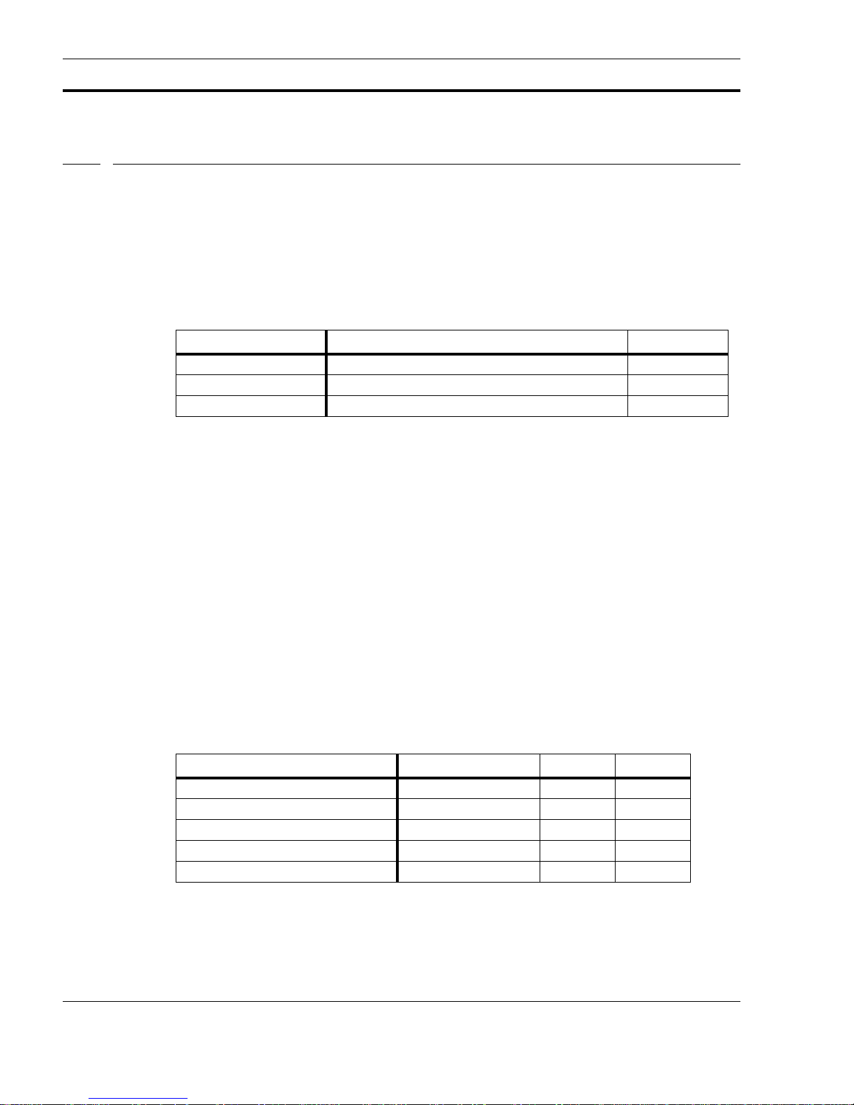
386EX are in their normal places. Extended I/O address mode is enabled at boot. Table 2.1 gives the I/O address
map for the CA386-N1 peripherals which are not part of the standard PC I/O space.
Table 2.1: CA386-N1 I/O Address Map
Address Range Device Chip Select
0x38C - 38D Neuron Chip CS1
0x38E-38F Network Address (redundantly mapped) CS3
0x390-39F RTC CS2
The CA386-N1 supports 16 digital I/O lines. Eight of these lines are input only. They exist on JP9 and can be
read as a single byte at I/O location 0x38e. If adjacent pins on JP9 are left open then a ‘1’ is read. Otherwise if a
shorting block is installed a ‘0’ is read.
The other 8 I/O lines are general purpose and connected directly to PORT1 of the 386EX CPU. They can be
accessed by the user as I/O lines DIO0 - DIO7 on J6. This port has three configuration registers and one status
register associated with it. The status register can be set as follows:
• P1CFG (0xf820) - This should always be set to 0x00 to use PORT1 as a digital I/O port.
• P1DIR (0xf864) - This selects the direction and function of a bit. Setting a bit in this register to '1' sets
the corresponding I/O to either an input or an open-drain output. Likewise setting a bit to ‘0’ sets the
corresponding bit to be a complementary output.
• P1LTC (0xf862) - This bit selects the desired output for an I/O pin in output mode.
Table 2.2 shows the possible pin configurations.
Desired Pin Configuration Desired Pin State P1DIR P1LTC
High-impedance input high impedance 1 1
Open-drain output high impedance 1 1
Open-drain output 0 1 0
Complementary output 1 0 1
Complementary output 0 0 0
Table 2.2: Digital I/O Pin Configurations
The register P1PIN (0xf860) may be read to get the current pin state. Reading this register returns the current pin
value, regardless of the pin’s mode and direction.
2-8 CA386-N1 REFERENCE MANUAL
Page 33

It is important to note that the address ranges specified above are in the expanded I/O space of the 386EX. On the
CA386-N1, the expanded I/O space is enabled by default, so no additional action is required to use the I/O. In
general, the expanded I/O space of the 386EX may be enabled from the application by performing the following
steps:
1. Disable interrupts.
2. Write byte 0x00 to I/O address 0x23.
3. Write byte 0x80 to I/O address 0x22.
4. Write word 0x0080 to I/O address 0x22.
5. Enable interrupts.
Note that after performing these steps all the standard PC compatible peripherals will be mapped into the DOS I/
O space. All the standard PC peripherals are mapped into the DOS I/O space upon DOS boot up, but may be
changed by user applications or drivers. Consult the Intel 386EX Embedded Micr oprocessor Hardware Refer ence
manual for more information concerning I/O address mapping.
2.6 Flash Loader
Flash Loader
The Flash loader program resides in the Flash memory of the CA386-N1. It provides a general download-to-flash
functionality. The Flash loader will begin execution upon power-up of the CA386-N1 if jumper JP1 is shorted.
The console port for the Flash loader is COM1. On start-up the Flash loader will display the following banner via
COM1:
2.6.1 General
The Flash loader processes one line at a time. Either <backspace> or <delete> will delete the last character typed.
and <esc> will discard the entire line. Initial spaces or tabs on the line will be ignored. <carriage-return> and/or
<newline> will terminate a line. Note that the Flash loader will process the line before sending a “@FL<car-
riage-return> <newline>
<newline> sequence, download programs should wait for the @FL prompt before sending the next line for processing. All numbers are in hexadecimal format. The baud command ('b') also accepts decimal numbers for clarity.
Note that a file download to the Flash loader is paced by the “@FL” prompts, and therefore the downloading program must wait for each “@FL” prompt before sending the next line.
All non-alphanumeric characters between arguments are treated as white space, i.e. everything except 0-9, A-F,
a-f, or ':' is equivalent to a space.
ABC
Flash loader. Copyright 1995 Coactive Aesthetics Inc.
(BFC4FC 230929)
@FL
” sequence to the screen. Since error messages may also send a <carriage-return>
NOTE: You must power-cycle the CA386-N1 between each .HEX file download.
2.6.2 Addresses
The Flash loader takes addresses in one of the following forms:
DOS Programming 2-9
Page 34

Flash Loader
• an offset within the current segment
• a segment offset pair
• a linear address
An address with 5 or more digits is taken to be a linear address (only 20 address bits are actually used) (e.g.
81234). An address with a colon (':') in it is taken to be a segment and offset (e.g. 8000:1234). Anything else is
taken to be a offset within the current segment. The current segment is the last one set with a '02' or '04' hex
record.
2.6.3 Memory Map
The Flash loader uses its own memory map independent of any applications. Note that the Flash will be shifted
from where it appears for DOS use. Use the command 'm C0000 80000' to map the Flash to its DOS configuration.
The memory map for the Flash loader is:
• 0x00000 - 0x3FFFF: RAM 256K
• 0x00000 - 0x7FFFF: RAM 1M, 4M
• 0x80000 - 0xFFFFF: Flash
2.6.4 Downloading a .HEX File to Flash
This section describes the steps for downloading a .HEX file to the CA386-N1 Flash memory.
• Short jumper JP1 during power-up.
• Start the Windows program TERMINAL.EXE (or equivalent) with the following settings:
• Set the port to be the one connected to COM1 on the CA386-N1.
• Set baud 9600, 8 bits, no parity.
• Text downloads in Line-By-Line mode. Wait for “@FL”.
• Boot the system. The Flash loader should start up.
• (optional) Type “b 19200" to the loader. Execute “Settings->Communications...” and set baud to
19200.Type <Enter> twice to get a prompt.
• Execute “Transfers->Send_Text_File...” and choose the .HEX file you wish to download. This will
take several minutes to complete, depending on file size. It may speed up the download to shrink the
Terminal window to a few lines or iconify it. When the download completes, type “s” at the “@FL”
prompt to see if any errors occurred (there should be none).
• (optional) Type “b 9600” to reset baud to 9600 (if step 4 abov e has been used). Reset Terminal’s com-
munications to 9600 with “Execute Settings->Communications...”. Type <Enter> twice to get a
prompt.
• Remove (un-short) jumper JP1.
NOTE: You must power-cycle the CA386-N1 between each .HEX file download.
2-10 CA386-N1 REFERENCE MANUAL
Page 35

2.6.5 Help Command
The “h” command displays all the commands supported by the Flash loader:
@FLh
Flash loader Copyright 1995 Coactive Aesthetics Inc
: ... Hex record
m A1 -> A2 Address remapping
w A1 -> A2 Address window
e A [L] Erase sectors containing A through A+L-1
d A [L] Display memory A through A+L-1
j [A] Set jump address (default from Hex load
b n Baud rate
a n Auto erase [1=on] 0=off
v n Verify mode [1=on] 0=off
s Show status
r Reboot
h You guessed it. Print this message
2.6.6 “:<.....>” (Hex Record)
Flash Loader
The “:” command indicates the start of a hex record being downloaded. Any line beginning with a colon is interpreted as a Intel hex record. If the checksum is not correct, the line is discarded with an error message, and the
error count is incremented. If the write is not successful, the message “operation failed” will be displayed and the
error count will be incremented.
If an address window is enabled and the hex record is outside the window, the message “not in window” is displayed. Note that the error count is not incremented in this case.
2.6.7 “m <A1> <A2>” (Address Remapping)
The “m” command takes two addresses, A1 and A2. Writes to the first address are mapped to the second address.
A1 may be greater than or less than A2. For example, “m C0000 80000” will map writes to C000:0 (the DOS
ROM disk) to 8000:0. Since the Flash will be shifted in memory when ROM-DOS is run, location 8000:0 in the
Flash loader will be location C000:0 under ROM-DOS.
Note that address re-mapping does not take effect until the next Extended Segment Address Record (i.e. a '02'
record) or Extended Linear Address Record (i.e. a '04' record) is encountered. Almost all
02 or 04 record to set the desired segment.
To disable address re-mapping, make A1 equal to A2, e.g. “m 0 0”.
2.6.8 “w <A1> <A2>” (Address Window)
The “w” command sets a range of physical addresses to which writing is allowed. Writes from A1 to A2 (inclusive, after address re-mapping) will be allowed. Writes outside this range will return a “not in window” message,
but will not increment the error count. This allows specific parts of a .HEX file to be loaded. To disable the write
window, make A1 higher than A2 (e.g. “w 2 1”).
.HEX files begin with a
DOS Programming 2-11
Page 36

Flash Loader
2.6.9 “e <A> [L]” (Erase Sectors)
The “e” command erases one or more sectors that contain the memory addresses A through A+L-1, inclusive. If
L is omitted, it is assumed to be 1. The sectors being erased are displayed.
2.6.10 “d <A> [L]” (Display Memory)
The “d” command displays the bytes at the memory addresses A through A+L-1, inclusive, in hexadecimal format. If L is omitted, it is assumed to be 1. Note that A will be converted to a normalized pointer before display.
Displaying more than 10000 bytes (64K) will cause a single sector to be displayed multiple times.
2.6.11 “j [A]” (Set Jump Address)
The “j” command sets the application start vector. When JP1 is not installed, the Flash loader passes control to
the segment and offset specified in A. If A is the same as the current start vector, no changes will be made.
The default for this command is the current start vector or the address specified by a Start Segment Address
Record (i.e. '03' record) or a Start Linear Address Record (i.e. '05' record). If this has been encountered in the
.HEX file, this value can been seen in the status display as the “hex load start address”. NOTE: This value may
be incorrect. Many
.HEX
files contain an invalid start address.
For ROM-DOS, the value B000:0 should be used. For iRMX, the value 8000:100 should be used.
This command is not present in some versions of the Flash loader program (i.e., hardware-locked).
2.6.12 “b <n>” (Set Baud Rate)
The “b” command sets the serial baud rate to the indicated value. Note that either decimal or hexadecimal number are allowed for <n>. The following baud rates are supported: 300, 1200, 2400, 4800, 9600, 19200, 38400,
and 57600.
2.6.13 “a <n>” (Auto Erase)
The “a” command sets a flag to enable automatic erase of a sector the first time it is written to. By default this is
set to allow .HEX files to automatically replace the old contents of the Flash. If automatic erase is off (i.e. “a 0”),
the “e” command must be used to erase any memory.
2.6.14 “v <n>” (Verify Mode)
The “v” command sets a flag to enable verification of a download. No data will be written to memory and no sectors will be erased. If the .HEX file data does not match the current memory contents, a message will be displayed
and the error count will be incremented.
2-12 CA386-N1 REFERENCE MANUAL
Page 37

2.6.15 “s” (Show Status)
The “s” command will display the current status of the Flash loader and controller. An example is shown below:
@FLs
Segment Bytes written
080000 000000
090000 000000
0A0000 000000
0B0000 000000
0C0000 000000
0D0000 000000
0E0000 000000
0F0000 000000
0F8000 000000
0FA000 000000
0FC000 000000
Baud: 0x002580
Errors: 0x0000
Auto Erase 01
Verify 00
From Address: 0C0000 To: 080000
Write window: 080000 - 0FBFFF
Application start address: B000:0000
Boot write enabled
Flash Disk Organization and Programming
Note that the error count is reset to 0 after an “s” command.
2.6.16 “r” (Reboot)
The “r” command will reboot the processor. If JP1 is shorted, the Flash loader will be re-initialized and restarted. If JP1 is not shorted, the application program will be executed.
2.7 Flash Disk Organization and Programming
There are two methods provided for writing data to the CA386-N1’ s Flash file system: (1) cop ying re gular “files”
using a special copy function, (2) using a low-lev el write function from an application. Method (1) is the simplest
since an application can use standard functions for normal file I/O (e.g., formatted I/O), and then “copy” the
entire file to Flash with a single function. Method (2) may be useful for special application requirements.
DOS Programming 2-13
Page 38

Peripherals
2.7.1 ROM Disks
The CA386-N1 is normally configured with two ROM Disks (C: and D:) stored in Flash. Currently the only way
in which to put files on these drives is to generate a new disk “image” using a special utility (DISK_IMG.BAT)
and then downloading this disk image to the board via the boot loader.
NOTE: Application programs cannot currently write to the ROM Disks. There is a special segment of Flash
reserved for application reading and writing, but this is not part of the DOS file system.
The utility DISK_IMG.BAT located in the rdos directory of the CA386-N1 Companion Diskette installation is
used to create new disk images in the form of .HEX files. These are then do wnloaded to the CA386-N1 using the
Flash loader (see Section 2.6, Flash Loader on how to use the Flash loader).
The following steps are used to create and download a new Flash disk by creating a new disk image:
•
• Run the DISK_IMG.BAT script (in the ca386\rdos\ directory).
• This will create various .HEX files which can be downloaded to create new ROM Disks and O/S’s.
Copy whichever files you wish to be on the ne w C: and D: drives to the C_DISK and D_DISK directories respectively (under
See the readme file in ca386\rdos\ for a description of all the options for the DISK_IMG.BAT
script. Follow the instructions for downloading these .HEX files to the Flash loader (see Section 2.6,
Flash Loader).
\ca386\rdos\, or wherever you installed the Companion Diskette).
NOTE: You must power-cycle the CA386-N1 between each .HEX file download.
2.8 Peripherals
The built-in peripherals of the CA386-N1 include:
• Interrupt Control Unit
• Timer/Counter Unit
• Asynchronous Serial I/O (COM1, COM2)
• Synchronous Serial I/O (SPI)
• DMA Controller
These peripherals are described fully in the Intel386EX Embedded Microprocessor Hardware Reference and
other documentation on the 80x86 architecture. The details of the Asynchronous Serial I/O are described below
since they differ somewhat from a standard PC.
All standard PC IO addresses supported by the 386ex are in the normal places. Extended IO address mode is disabled at boot, but can be re-enabled by any application that requires it.
2-14 CA386-N1 REFERENCE MANUAL
Page 39
2.8.1 Serial Ports
The Asynchronous Serial I/O Units (UARTs) on the CA386-N1 are accessed as in the standard PC architecture.
Base addresses for the two on-board serial ports (COM1, COM2) are as in the standard PC architecture.
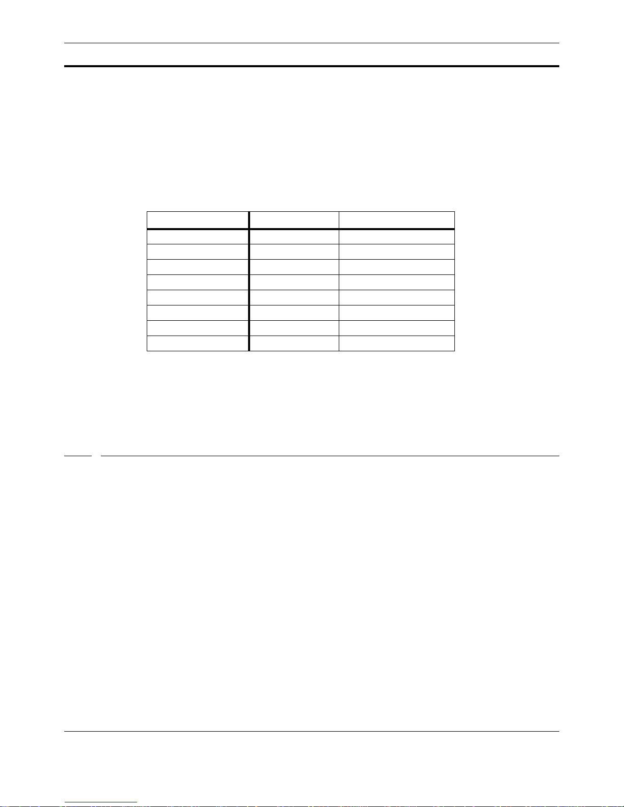
Normally on a standard PC the baud-rate clock divisor for a UART is 12 for 9600 baud. On the CA386-N1 the
divisor for 9600 baud is 81 (0x51). Divisors for standard baud rates are given in the table below.
Troubleshooting
Baud Rate Divisor (HEX) Divisor (Decimal)
1200 0x028C 652
2400 0x0146 326
4800 0x00A3 163
9600 (default) 0x0051 81
19200 0x0029 41
38400 0x0014 20
57600 0x000E 14
115200 0x0007 7
Table 2.3: Baud-Rate Clock Divisors for the CA386-N1 UARTs
NOTE: Due to these diff erences in divisors from a standard PC, applications which write directly to the UART
to reset the baud rate may not work correctly.
2.9 Troubleshooting
2.9.1 Communicating with the CA386-N1
2.9.1.1 I run “comm.exe” but do not see the DOS prompt.
• Did you start COMM.EXE with the options \B9600 /ComX where X is the number of the COM port of
the desktop PC you are using with your terminal program?
• Is the CA386-N1 powered?
• Is the COM port you are using from the desktop PC’s terminal program connected to COM2 of the
CA386-N1 (DOS console port) with a straight-through cable?
• Is the COM port you are using in use by another application? The COMM.EXE program will NOT com-
plain in this case, it will just not work. Make sure other apps that may be using the port are shut down,
then re-try COMM.EXE.
2.9.1.2 I experience problems whenever I try to copy or download files to drives C or D.
• Drives C: and D: are READ ONLY. You cannot write files to these drives using any DOS utility or
application. You can, however, put files on these drives by re-creating the disk image and downloading it via the boot loader.
DOS Programming 2-15
Page 40

Troubleshooting
2.9.1.3 After Downloading a new ROM Disk, I power-cycle, and do not get the DOS prompt.
• The DOS console on the CA386-N1 is COM2 (header J2). Make sure this is what you are connected
to.
• Make sure JP1 is not shorted. If shorted, only the Flash loader will run (using COM1).
2-16 CA386-N1 REFERENCE MANUAL
 Loading...