

Page 1
Game Day Guide
Wired Interface
Getting Started
This Game Day Guide is a basic reference for setting up your X-System. For complete operation instructions, see the
X-System Operating Manual, which is available on CoachComm’s website at: www.coachcomm.com/x-system.
CAUTION: Allow only responsible, authorized individuals who have read all of the instructions and warnings to set up and
operate your X-System.
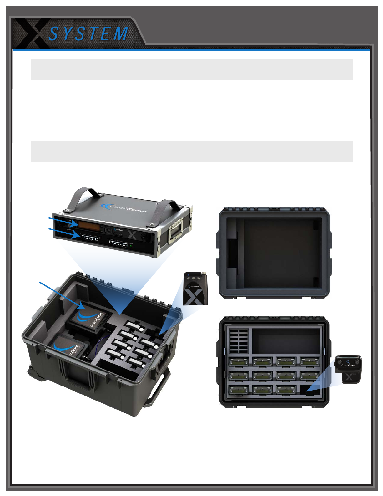
X2 Package Overview
Press Box Rack Unit
Accessory Case
Control Unit
Field Antennas
with Mounting
Hardware
Press Box Case
Wired BeltPack
Storage for the following:
• 15 ft. Duracat 5 Cable
• 50 ft. Duracat 5 Cable
• 100 ft. Cat 5 Cable
• 25 ft. Bundled Cat 5 Wired
BeltPack Cable
• Booth Coaches’ Headsets
• Booth Antenna and Accessories
(if applicable)
Sideline Case
Storage for Batteries*,
Chargers, and Power Cords
Radio Pack
(Sideline headset storage in bottom)
*Spare lithium batteries are not allowed in
checked airline baggage. Be sure to follow
all air travel rules and regulations when
traveling with your X-System.
Page 2

50 4040
5040 40
50 4040
5040 40
Your Sideline
Your Sideline
OR
First Field Antenna Second Field Antenna
Optional Booth Antenna
Pressbox
Rack Unit
Game Day Guide
1
Set up Press Box Rack Unit.
1a. Unpack the press box and accessory cases.
1b. Position the Press Box Rack Unit out of the way to avoid coaches and other trafc.
1c. Connect power to the Press Box Rack Unit, but do NOT turn on the Control Unit (CU) yet. The
“Power” LED on the front of the Wired Interface should be lit green.
Important: X-System requires a minimum of one dedicated 15 amp 120V circuit.
2
Mount and connect the Antenna.
2a. Using either the clamp or suction cup mounting hardware, secure the antenna bracket so that the antenna’s logo points
toward the center of your team’s coaches’ box.
Note: Any obstructions between
the antenna and eld
(like window tinting)
can negatively impact
performance. CoachComm
recommends opening
windows or mounting
the antenna externally to
the press box. We also
recommend covering
antennas with a clear
plastic bag or a rain cover
in the event that rain is expected.
Connect a Cat 5 cable to the X-NET IN port on the antenna.
2b.
2c. Connect the other end of the Cat 5 cable to the FIELD ANTENNA port on the Press Box Rack Unit’s rear panel.
(1c.) Power LED
2d. If using a second eld antenna, conrm the short Cat 5 cable is properly connected between the rst antenna’s RT LOOP
port and the second antenna’s X-NET IN port.
Note: If applicable, a third antenna for booth wireless can be connected as outlined in the diagram below.
CAUTION: Secure and protect any cords to prevent walkway hazards and potential contact with moisture.
Cables not shown
Page 3
Power on the Control Unit.
3
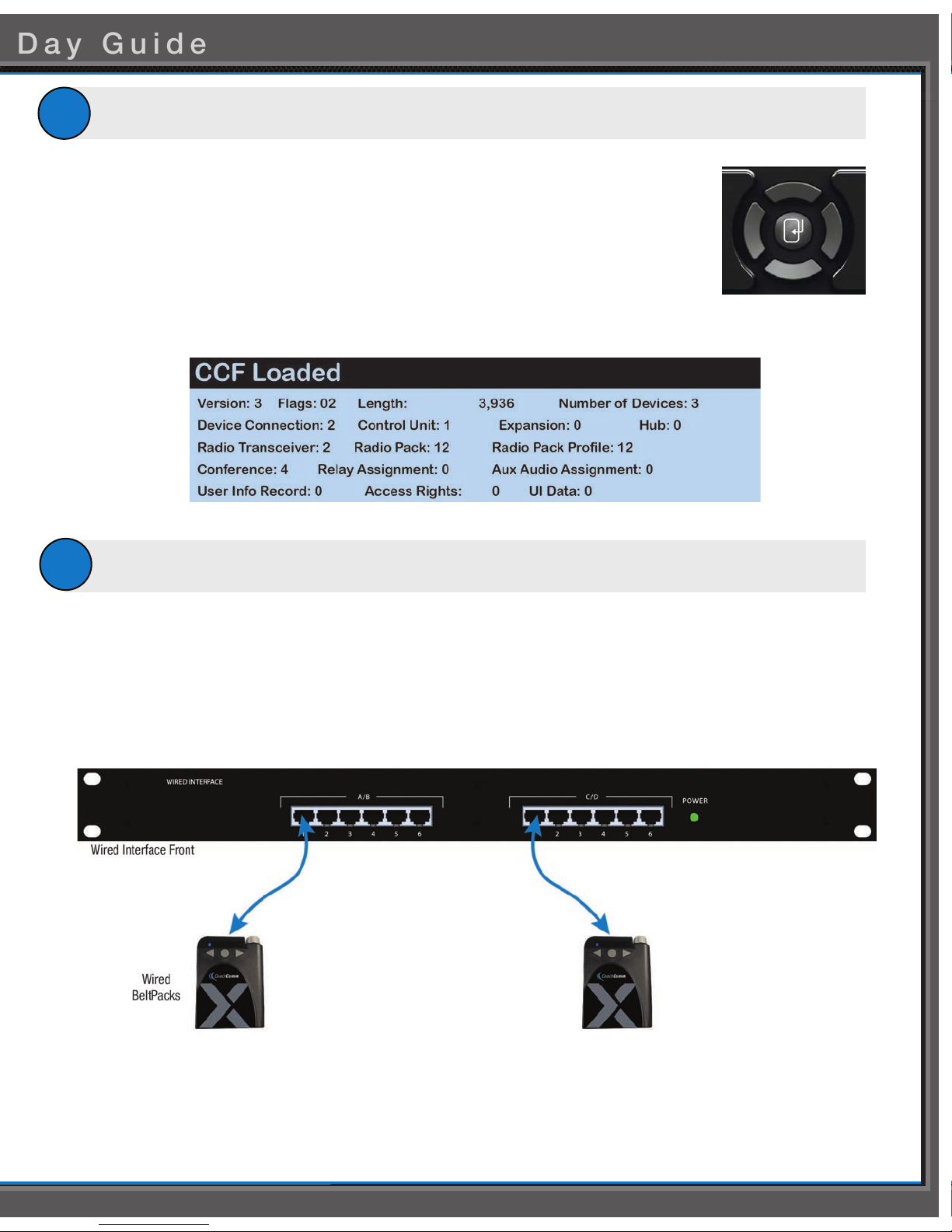
3a. Power ON the CU via the power switch on its front panel.
3b. Use CU navigational controls to select
Important: No RF transmission will occur until the Home/Away status is selected. Failure to set this
status properly may result in RF interference if and when the opposing team is also using
an X-System. It is important to coordinate with opponents to ensure optimal performance
for both teams.
3c. Wait until the CU displays the following message: “CCF Loaded” along with a conguration le
summary. Once the message times out, the home screen will display on the front of the CU.
(3c.) Sample CCF Loaded Screen
Set up the Wired Interface and Wired BeltPacks.
4
The procedures in this step should be performed with at least two people.
Home
or
Away
and press the Enter button.
(3b.) CU Navigation Buttons
4a. Place a Wired BeltPack at each coach’s position in the press box.
4b. Connect the short end of the Cat 5 cable bundle to the desired channels on front of the Wired Interface (A/B or C/D).
4c. Connect the opposite ends of the bundled cables to each Wired BeltPack.
Important: Keep cables out of the way of coaches and heavy foot trafc. Cables that are pinched, snagged, or damaged will
cause disrupted communication.
4d. Connect a headset to each Wired BeltPack.
4e. Power on each Wired BeltPack by turning the volume knob clockwise. The lights on the front of the BeltPack will
illuminate when powered on. Conrm that each Talk button is off.
4f. Put on one headset and press the Talk button on the Wired BeltPack and conrm that you can communicate with a
second Wired BeltPack on both channels with no crosstalk. Repeat the test for each Wired BeltPack.
Page 4
Game Day Guide
Power on and walk test Radio Packs.
5
The procedures in this step should be performed with at least two people.
8
(5b.) Turn on by
holding Power button
for 3 seconds.
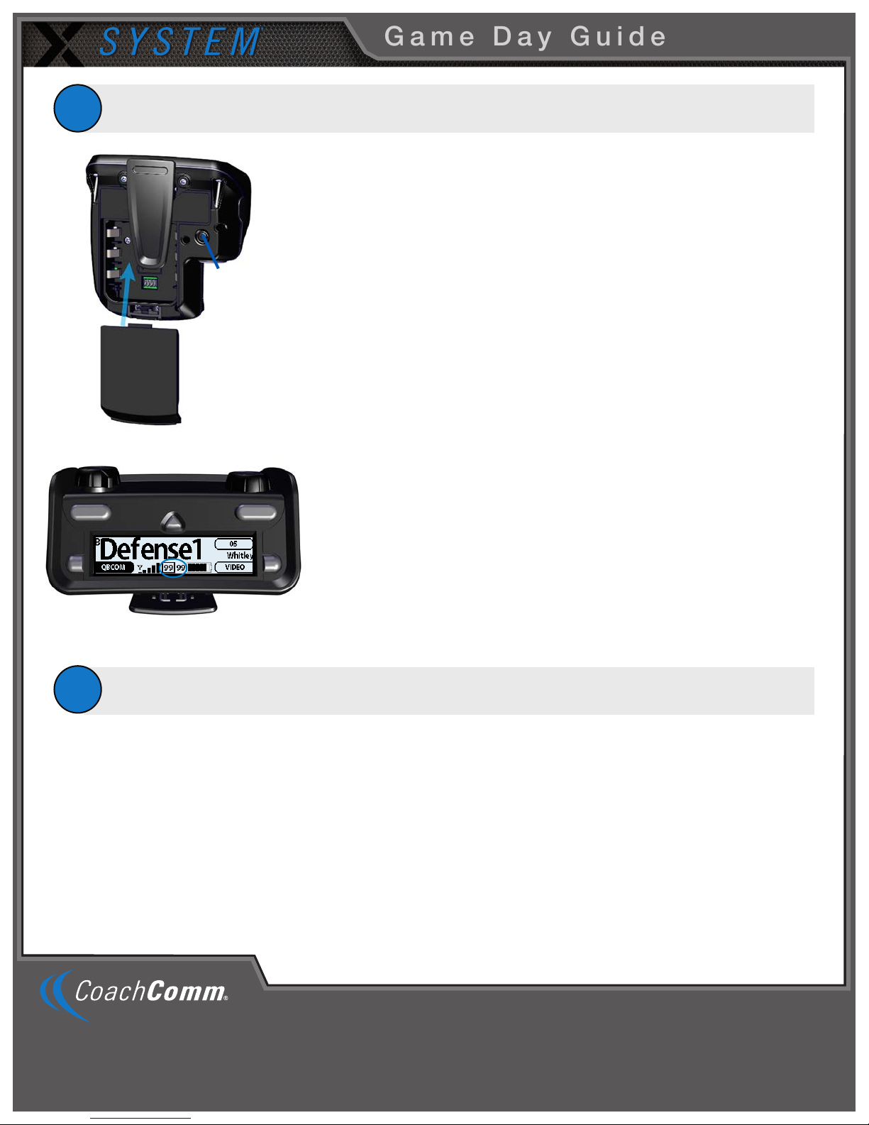
(5a.) Install battery.
On the sideline, unpack the sideline case and install one of the provided, fully
5a.
charged Lithium-Polymer rechargeable batteries or three AA batteries in each
Radio Pack (RP).
5b. Power on the rst two RPs by pressing and holding the Power button on the
back of the RP for 3 seconds.
Conrm each RP is on the same conference, connect a headset to each RP,
5c.
and conduct a walk test to conrm their operation. The RP’s LQ value can be
used to gauge performance. See the
information about LQ values.
X-System Operating Manua
l for more
Important:
5d.
(5c.) Check LQ.
Important: If raining, cover the RPs or return them to their cases.
5e. Conrm communication between wireless and wired coaches.
Power off and stow away.
6
Once your game has ended, power off and properly stow away all components:
6a. Power off all RPs and stow them with the eld headsets in the sideline case.
Each tester should walk their Wireless RPs to opposite goal lines and
back, ensuring clear communication between all Wireless RPs. Always
place the Wireless RP on the hip opposite from the press box when walk
testing.
After walk testing is complete, place the RP down on a table or bench. Be sure
to place each RP a foot or so apart; bunching RPs together could impact
wireless performance. Repeat steps 5b-5c for each of the remaining RPs.
6b. Power off and disconnect all Wired BeltPacks and stow them in the press box case.
Power off the CU and disconnect the Cat 5 cable between the Press Box Rack Unit and the antennas. Carefully disassemble
6c.
and stow the antennas and mounting hardware in the appropriate case.
6d. Coil all cables and stow them with the press box headsets in the accessory case.
6e. Disconnect power from the Press Box Rack Unit and stow it in the press box case.
Important: Thoroughly dry off any moisture prior to storage. Failure to do so can cause components to corrode and damage.
205 Technology Parkway
Auburn, Alabama 36830
While CoachComm makes every attempt to maintain the accuracy of the information contained in this document, this information is subject to change without notice.
Please check our website for the latest system specications and certications. Copyright © 2018 CoachComm LLC. All rights reserved. The X-System logo is a
trademark of CoachComm LLC. All other trademarks are property of their respective owners. Document Reference: 2018.02 D0000384_A
www.coachcomm.com
Phone 1.800.749.2761
Fax 1.888.329.2658
 Loading...