

Page 1
Operating Manual
X2 Package
Page 2

OPERATING MANUAL
Thank you from CoachComm!
We at CoachComm want to thank you for purchasing an X-System Sideline Communications System. We have made every
effort to build a reliable, intuitive communication system that provides the functionality that you can count on come game
day.
One of our goals in the design of X-System was to build on the advances set forth by the previous Tempest® NG System and
to provide users with unmatched RF performance. You will be able to begin using your new X-System with nothing more
than the Game Day Guide. However, to fully benet from the available features, please read this manual carefully.
We want X-System to make your job easier and your game day experience positive. To successfully familiarize yourself with
the many diverse and powerful features X-System offers, it is crucial that you acquaint yourself with the manual. Your time
spent will help you get the most from your X-System by making setup quick and easy.
We are committed to providing you with a high quality product that will deliver years of trouble-free service. Should you
experience any problem with your X-System equipment, whether it is under warranty or not, we will be there to take care of
your needs.
Thank you for choosing CoachComm for your sideline communication needs.
CoachComm LLC
205 Technology Parkway
Auburn, AL 36830
Phone: 334-321-2300
Fax: 888-329-2658
www.coachcomm.com
© 2018 CoachComm LLC. All rights reserved.
Document Reference: 2018.03 D0000383_A
© Telex is a registered trademark of Telex Communications, Inc.
800.749.2761 www.coachcomm.com
ii
Page 3

OPERATING MANUAL
Table of Contents
Safety Information ................................................................................................................................................1
Electrical Safety ..............................................................................................................................................1
Battery Safety .................................................................................................................................................2
Protecting Yourself and Those Around You .......................................................................................................2
X2 Block Diagram .................................................................................................................................................3
Introduction ..........................................................................................................................................................4
What makes X-System so different? ...............................................................................................................4
Frequency Considerations ...............................................................................................................................4
Game Day Setup ...................................................................................................................................................5
X-System Components .........................................................................................................................................9
X2 Package Overview .....................................................................................................................................9
Press Box Rack Unit Overview ......................................................................................................................10
Wired Interface (WI) ......................................................................................................................................11
Control Unit (XCU-44)....................................................................................................................................13
Radio Transceiver/Antenna (XRT-ANT-900) ...................................................................................................17
Radio Packs (XRP-13) ..................................................................................................................................19
System Accessories ............................................................................................................................................25
Press Box Cables ..........................................................................................................................................25
Headsets ......................................................................................................................................................25
System Setup and Operation ...............................................................................................................................26
Mounting Antennas .......................................................................................................................................26
Covering Your Antennas ................................................................................................................................28
Setting Home/Away Status ...........................................................................................................................28
Walk Testing Your System .............................................................................................................................29
Understanding Link Quality ..........................................................................................................................29
X-Ware Setup and Installation .............................................................................................................................30
System Requirements...................................................................................................................................30
Installing X-Ware ..........................................................................................................................................30
Connecting X-Ware to Your CU ......................................................................................................................32
X-Ware Operation ...............................................................................................................................................34
Home Screen ................................................................................................................................................34
Prole Screen ...............................................................................................................................................35
Additional System Views ...............................................................................................................................38
X-Ware Advanced Settings ............................................................................................................................40
System Conguration File ...................................................................................................................................41
Saving a Conguration File ...........................................................................................................................41
Loading a Conguration File .........................................................................................................................41
System Maintenance ..........................................................................................................................................43
Basic Maintenance .......................................................................................................................................43
Lithium-Polymer Battery Maintenance ..........................................................................................................43
Storage of your Lithium-Polymer Batteries ...................................................................................................43
Updating X-Ware ..........................................................................................................................................44
Updating Device Firmware ............................................................................................................................45
Troubleshooting Common Issues .........................................................................................................................48
Returning Equipment for Repair or Maintenance ..........................................................................................49
License Information ............................................................................................................................................50
Radio Device License Information .................................................................................................................50
800.749.2761 www.coachcomm.com
iii
Page 4

OPERATING MANUAL
Non-Radio-Device License Information .........................................................................................................51
Warranty Information ..........................................................................................................................................52
Limited Warranty ..........................................................................................................................................52
Parts Limited Warranty .................................................................................................................................52
Specications .....................................................................................................................................................54
Control Unit Specications ...........................................................................................................................54
Radio Transceiver/Antenna Specications ....................................................................................................55
Radio Pack Specications .............................................................................................................................56
800.749.2761 www.coachcomm.com
iv
Page 5

OPERATING MANUAL
Safety Information
The following pages detail important safety information related to the ownership and operation of CoachComm’s X-System.
Please ensure all personnel review the warnings and safety recommendations included in this document before operating
X-System in order to prevent equipment damage and/or serious personal injury.
Throughout this document you will see the following indicators for important safety information and alerts:
WARNING: Ignoring these warnings may cause permanent or serious injury or death as a result of
incorrect operation.
CAUTION: Ignoring these cautions may cause moderate injury or property damage as a result of
incorrect operation.
Electrical Safety
WARNING: ELECTRIC SHOCK RISK
» Do not submerge any part of X-System in water.
» Refer all servicing to qualied service personnel. Do not attempt to modify, disassemble, or open any
X-System components. Exposing the electrical system may result in equipment damage and serious
personal injury, including electric shock. Equipment damage caused by unqualied personnel may void the
product warranty associated with your X-System.
CAUTION: SYSTEM DAMAGE RISK
» Protect the power cords from foot trafc. Do not allow cords to be crimped or pinched, particularly at plugs,
electrical outlets, and the point they exit from the apparatus. Routinely inspect power cords for any signs of
fray or extensive wear. Immediately replace any damaged cords.
» Keep all ventilation openings clean and unobstructed. Failure to do so could cause the system to overheat,
which could cause personal injury or property damage.
» Unplug X-System during lightning storms to prevent power surges that could damage electrical
components or cause re.
800.749.2761 www.coachcomm.com
1
Page 6
OPERATING MANUAL
Battery Safety
Radio Pack (RP) Battery Safety
WARNING: EXPLOSION AND FIRE RISK
» Battery explosion is possible if incorrect type is used. Use only batteries approved for use with X-System
Radio Packs. If powering the Radio Pack with AA batteries, use only alkaline or carbon-zinc batteries.
» Do not leave the battery unattended while charging. Immediately unplug unit if battery begins to swell
or emit smoke while charging. If battery bursts or chemicals begin to leak out of battery housing, the
chemicals will react with the air and cause a re.
» CoachComm recommends keeping a Class-D re extinguisher available when charging lithium-polymer
batteries. The chemicals inside lithium-polymer batteries are highly ammable.
» Do not allow batteries to overheat (reach temperatures of above 140 degrees Fahrenheit).
» Batteries that appear swollen, deformed, or damaged, or that do not t properly should never be used.
Properly dispose of any batteries in this condition in accordance with the instructions provided by your local
authorities. For more information and local drop-off sites, visit http://www.call2recycle.org/.
Protecting Yourself and Those Around You
Allow only responsible individuals who are familiar with these general safety rules and operating instructions to use your
X-System. Never allow people unfamiliar with these rules and instructions to set up or operate your system.
CAUTION: SYSTEM DAMAGE AND INJURY RISK
» Never, under any conditions, remove, bend, cut, t, weld, or otherwise alter standard parts of the X-System.
Modications to your system could cause personal injuries and property damage and will void your
warranty.
» Only use attachments/accessories/cables/antennas/hardware provided by the manufacturer.
» Do not remove or cover any safety labels. If a label is damaged or removed, contact a CoachComm support
technician for a replacement.
» Do not mount the Radio Transceiver/Antenna suction cup directly over heads, if possible. If unavoidable, it
is imperative that you use the included safety lanyard to secure the suction cup to a xed anchor point to
prevent damage or injury from falling objects.
800.749.2761 www.coachcomm.com
2
Page 7
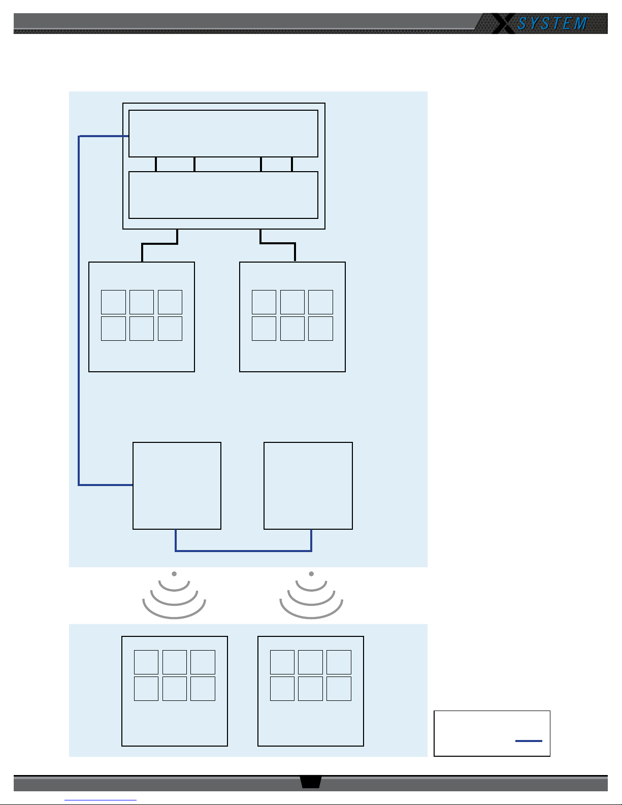
X2 Block Diagram
Control Unit
Wired Interface
OPERATING MANUAL
Press Box
Rack Unit
A/B
Wired Users (x6)
Antenna
C/D
Wired Users (x6)
Antenna
Wireless Users
(x6)
800.749.2761 www.coachcomm.com
Wireless Users
(x6)
3
Legend
Cat 5e (max of 330 ft)
Page 8

OPERATING MANUAL
Introduction
What makes X-System so different?
CoachComm has been building and providing wired and wireless systems for over 25 years to supply quality
communications and practice equipment to every level of football nationwide. Championship-winning teams have found
condence in our Tempest FX system, Connex system, and most recently our X-System. Our latest solution combines the
mobility and functions you’re familiar with from Tempest FX and pairs it with our latest development in design and agility
from the X-System.
X-System makes use of the newest available communications technology and meets our customers’ demands for more
users, better audio, and future-based features.
X-System is the rst wireless communications system to innovate the following unique features:
• Better Frequency-Hopping Spread Spectrum performance in dome venues
• Enhanced 900MHz wireless performance
• Better 7k audio quality
• High Density mode provides ability to add as many coaches as you need
• X-Ware software user interface for monitoring and customizing the X-System
These features come together to form a powerful product called X-System. X-System, together with enhanced tools for the
wired portion of the system, makes for an incredibly robust, easy-to-operate system.
Frequency Considerations
900MHz
CoachComm designed the new X-System to operate seamlessly in the 900MHz frequency band. This allows multiple
devices to operate within the band with minimal interference or reduction of range and performance.
The 900MHz ISM frequency band is a portion of the RF spectrum available for unlicensed use in North America and other
various locations with no frequency coordination. In North America the 900MHz band is 902–928 MHz. X-System utilizes up
to 26 MHz of this spectrum.
Frequency-Hopping Spread Spectrum
Frequency-Hopping Spread Spectrum (FHSS) is a means of RF transmission. In FHSS, the signal hops to various
frequencies—hence the name. In doing so, it spreads the data (voice in our case) across a wide area of the RF spectrum.
Devices such as those in X-System collide constantly with other devices in that frequency spectrum and must have
mechanisms built into their protocol to allow for data redundancy to provide acceptable user performance.
800.749.2761 www.coachcomm.com
4
Page 9
OPERATING MANUAL
50 4040
5040 40
50 4040
5040 40
Your Sideline
Your Sideline
OR
Game Day Setup
The procedures in this section serve as a reference for a typical game day setup. You can nd more in-depth information
about the devices and processes mentioned here in later sections of this Operating Manual.
CAUTION: Allow only responsible, authorized individuals who have read all of the instructions and
warnings to set up and operate your X-System.
1. Set up Press Box Rack Unit.
1a. Unpack the press box and accessory cases.
1b. Position the Press Box Rack Unit out of the way to avoid coaches and other trafc.
1c. Connect power to the Press Box Rack Unit, but do NOT turn on the Control Unit (CU) yet. The
“Power” LED on the front of the Wired Interface should be lit green.
Important: X-System requires a minimum of one dedicated 15 amp 120V circuit.
Figure 1: Power LED
2. Mount and connect the Antenna.
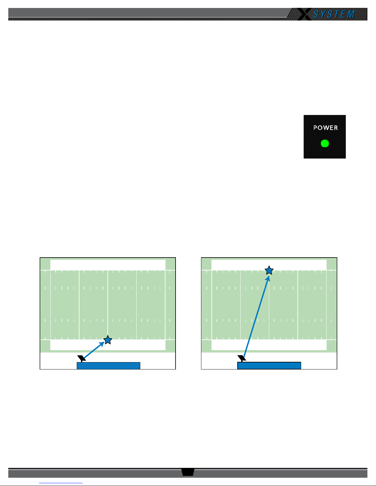
2a. Using either the clamp or suction cup mounting hardware, secure the Antenna bracket so that the Antenna’s
logo points toward the center of your team’s coaches’ box. See page 26 of this manual for more instructions if
needed.
Note: Any obstructions between the Antenna and eld (like window tinting) can negatively impact
performance. CoachComm recommends opening windows or mounting the Antenna externally to
the press box. We also recommend covering Antennas with a clear plastic bag or a rain cover in
the event that rain is expected.
Figure 2: Antenna Pointed Toward Center of Your Team’s Coaches’ Box
800.749.2761 www.coachcomm.com
5
Page 10

OPERATING MANUAL
2b. Connect a Cat 5 cable to the X-NET IN port on the Antenna.
2c. Connect the other end of the Cat 5 cable to the FIELD ANTENNA port on the Press Box Rack Unit’s rear panel.
2d. If using a second eld Antenna, conrm the short Cat 5 cable is properly connected between the rst Antenna’s RT
LOOP port and the second Antenna’s X-NET IN port.
Note: If applicable, a third Antenna for booth wireless can be connected as outlined in the diagram below.
CAUTION: Secure and protect any cords to prevent walkway hazards and potential contact with moisture.
First Field Antenna Second Field Antenna
Pressbox
Rack Unit
Figure 3: Press Box Rack Unit Connections to Antennas
3. Power on the Control Unit.
3a. Power ON the CU via the power switch on its front panel.
3b Use CU navigational controls to select
Home
or
Away
and press the Enter button.
Optional Booth Antenna
Important: No RF transmission will occur until the Home/Away status is selected. Failure to set
this status properly may result in RF interference if and when the opposing team
is also using an X-System. It is important to coordinate with opponents to ensure
optimal performance for both teams.
Figure 4: CU Navigation Buttons
3c. Wait until the CU displays the following message: “CCF Loaded” along with a conguration le summary. Once the
message times out, the home screen will display on the front of the CU.
Figure 5: Sample CCF Loaded Screen
800.749.2761 www.coachcomm.com
6
Page 11
OPERATING MANUAL
4. Set up the Wired Interface and Wired BeltPacks.
The procedures in this step should be performed with at least two people.
4a Place a Wired BeltPack at each coach’s position in the press box.
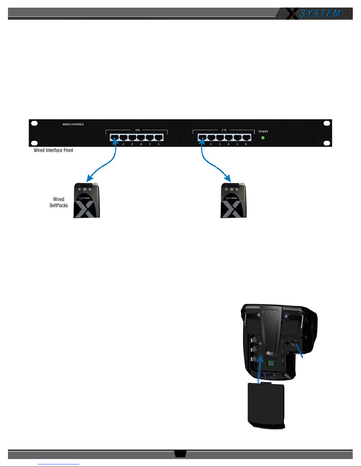
4b Connect the short end of the Cat 5 cable bundle to the desired channels on front of the Wired Interface (A/B or
C/D).
4c. Connect the opposite ends of the bundled cables to each Wired BeltPack.
Important: Keep cables out of the way of coaches and heavy foot trafc. Cables that are pinched,
snagged, or damaged will cause disrupted communication.
Figure 6: Wired Interface Connection to Wired BeltPacks
4d. Connect a headset to each Wired BeltPack.
4e. Power on each Wired BeltPack by turning the volume knob clockwise. The lights on the front of the BeltPack will
illuminate when powered on. Conrm that each Talk button is off.
4f. Put on one headset and press the Talk button on the Wired BeltPack and conrm that you can communicate with a
second Wired BeltPack on both channels with no crosstalk. Repeat the test for each Wired BeltPack.
5. Power on and walk test Radio Packs.
The procedures in this step should be performed with at least two people.
5a. On the sideline, unpack the sideline case and install one of the
provided, fully charged Lithium-Polymer rechargeable batteries or
three AA batteries in each Radio Pack (RP).
5b. Power on the rst two RPs by pressing and holding the Power
button on the back of the RP for 3 seconds.
Figure 7: Turn on by
holding Power button for 3
seconds.
Figure 8: RP Battery Installation and Power On
800.749.2761 www.coachcomm.com
7
Page 12
OPERATING MANUAL
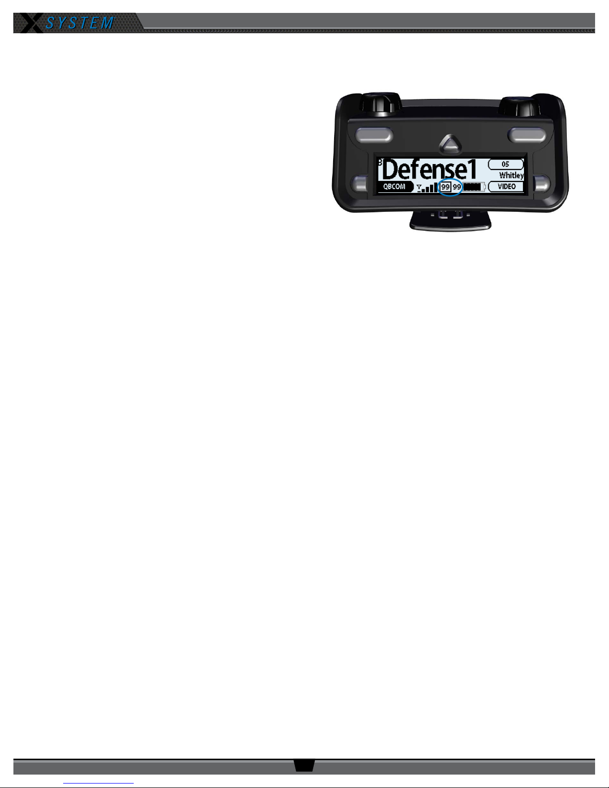
5c. Conrm each RP is on the same conference, connect a headset to each RP, and conduct a walk test to conrm
their operation. The RP’s LQ value can be used to gauge performance. See page 29 for more information about
LQ values.
Important: Each tester should walk their RPs to
opposite goal lines and back, ensuring
clear communication between all RPs.
Always place the RP on the hip opposite
from the press box when walk testing.
5d. After walk testing is complete, place the RP down on
a table or bench. Be sure to place each RP a foot or so
apart; bunching RPs together could impact wireless
performance. Repeat steps 5b-5c for each of the
remaining RPs.
Figure 9: Check LQ Values
Important: If raining, cover the RPs or return them to
their cases.
5e. Conrm communication between wireless and wired coaches.
6. Power off and stow away.
Once your game has ended, power off and properly stow away all components:
6a. Power off all RPs and stow them with the eld headsets in the sideline case.
6b. Power off and disconnect all Wired BeltPacks and stow them in the press box case.
6c. Power off the CU and disconnect the Cat 5 cable between the Press Box Rack Unit and the Antennas. Carefully
disassemble and stow the Antennas and mounting hardware in the appropriate case.
6d. Coil all cables and stow them with the press box headsets in the accessory case.
6e. Disconnect power from the Press Box Rack Unit and stow it in the press box case.
Important: Thoroughly dry off any moisture prior to storage. Failure to do so can cause components to
corrode and damage.
800.749.2761 www.coachcomm.com
8
Page 13
X-System Components
Press Box Rack Unit
Wired Interface
Accessory Case
Radio Pack
Sideline Case
Storage for Batteries*,
Chargers, and Power Cords
(Sideline headset storage in bottom)
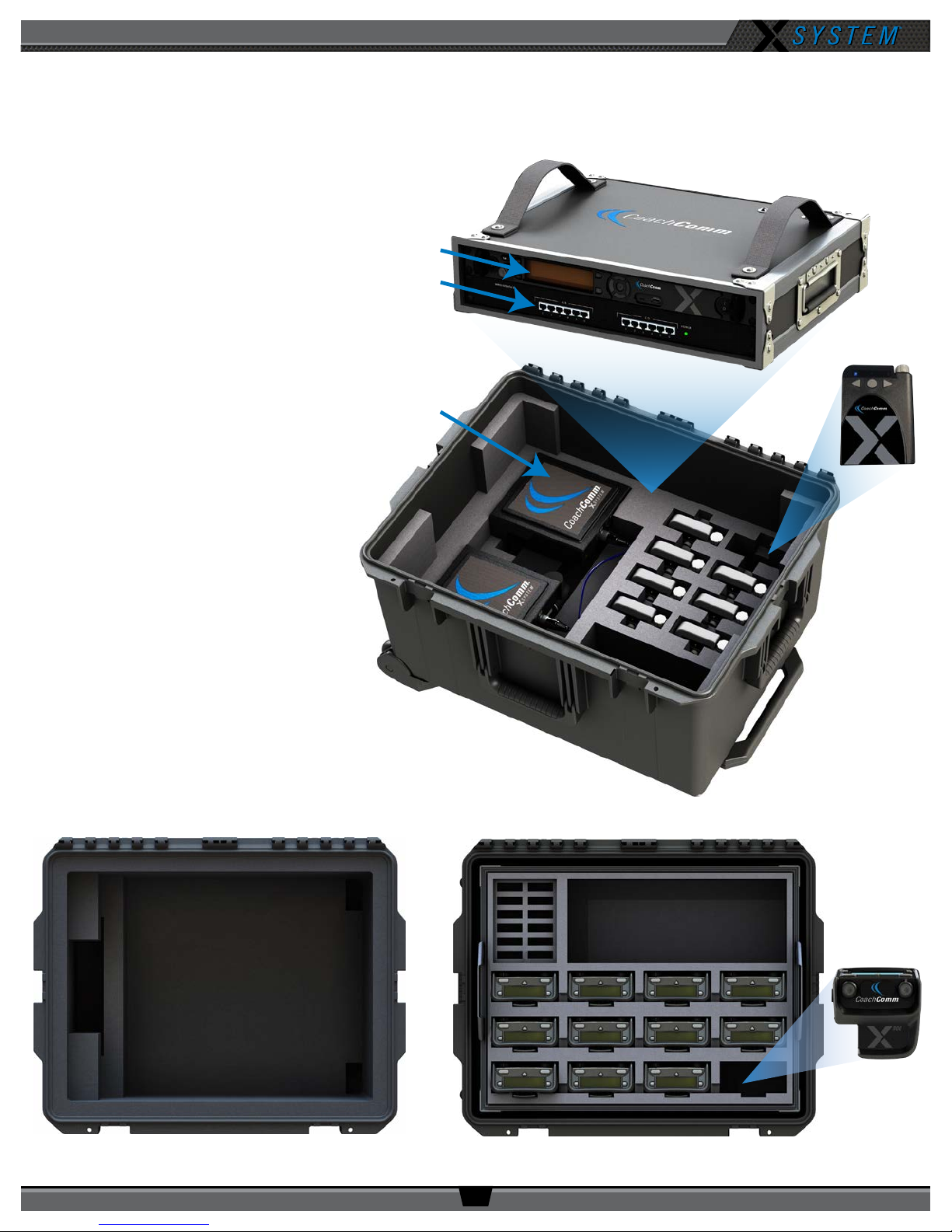
X2 Package Overview
The X2 package for X-System consists
of three cases that provide storage for
the sideline and press box components
of the system. The press box case and
accessory case should be placed in the
applicable press box for your team. The
sideline case should be placed on your
team’s sideline. Further instructions
about setting up your system are
provided in the Game Day Setup section
of this manual on page 5.
*Spare lithium batteries are not allowed in
checked airline baggage. Be sure to follow
all air travel rules and regulations when
traveling with your X-System.
Control Unit
Field Antennas
with Mounting
Hardware
OPERATING MANUAL
Wired BeltPack
Storage for the following:
• 15 ft. Duracat 5 Cable
• 50 ft. Duracat 5 Cable
• 100 ft. Cat 5 Cable
• 25 ft. Bundled Cat 5 Wired
BeltPack Cable
• Booth Coaches’ Headsets
• Booth Antenna and Accessories
(if applicable)
Press Box Case
800.749.2761 www.coachcomm.com
9
Page 14

OPERATING MANUAL
B C
Press Box Rack Unit Overview
The Press Box Rack Unit houses the system’s Wired Interface, Control Unit, and antenna connection panel. See page 11
of this manual for more information about the Wired Interface, and see page 13 for more information about the Control
Unit.
Press Box Rack Unit Rear
A
Cables not shown.
Figure 10: Press Box Rack Unit Rear View
A. FIELD ANTENNA Port – Connection for the Cat 5 cable from the eld antenna(s).
B. SYNC IN Port – Allows the system to be synchronized with another X-System. Sync is recommended when more
than two unsynchronized X-System Antennas are operating in close proximity to one another.
C. BOOTH ANTENNA Port – Connection for the Cat 5 cable from a booth antenna.
Note: Audio and power cables are not pictured in Figure 10.
Find more information about connecting antennas to the system on pages 5 and 26 of this manual.
800.749.2761 www.coachcomm.com
10
Page 15
OPERATING MANUAL
B
C
A
A CB D E F
Wired Interface (WI)
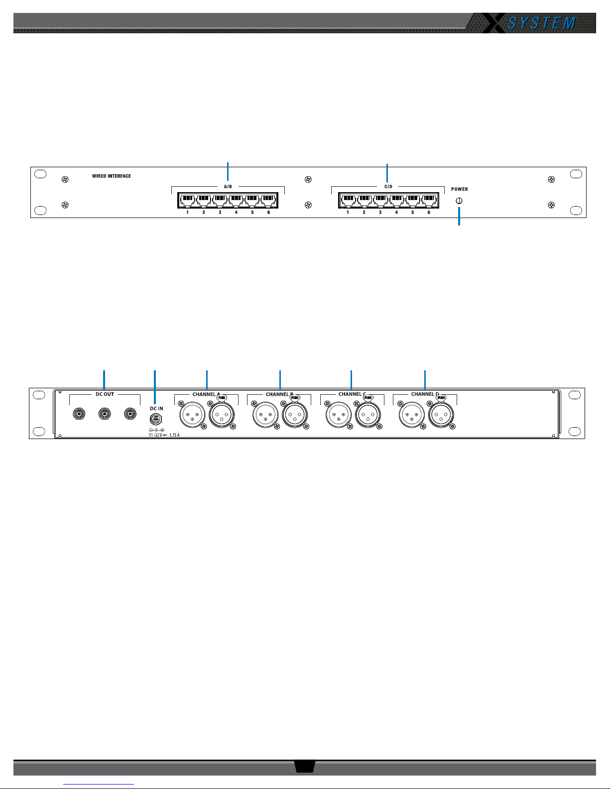
The Wired Interface (WI) is located in the main rack unit in the press box with the Control Unit (CU). The interconnectivity
between the WI and the CU is pre-wired at CoachComm.
Wired Interface Front
Figure 11: Wired Interface Front View
A. Power LED
B. Channel A/B Ports
C. Channel C/D Ports
Wired Interface Rear
Figure 12: Wired Interface Rear View
A. DC Power Out – Not currently used with X-System operation
B. DC Power In
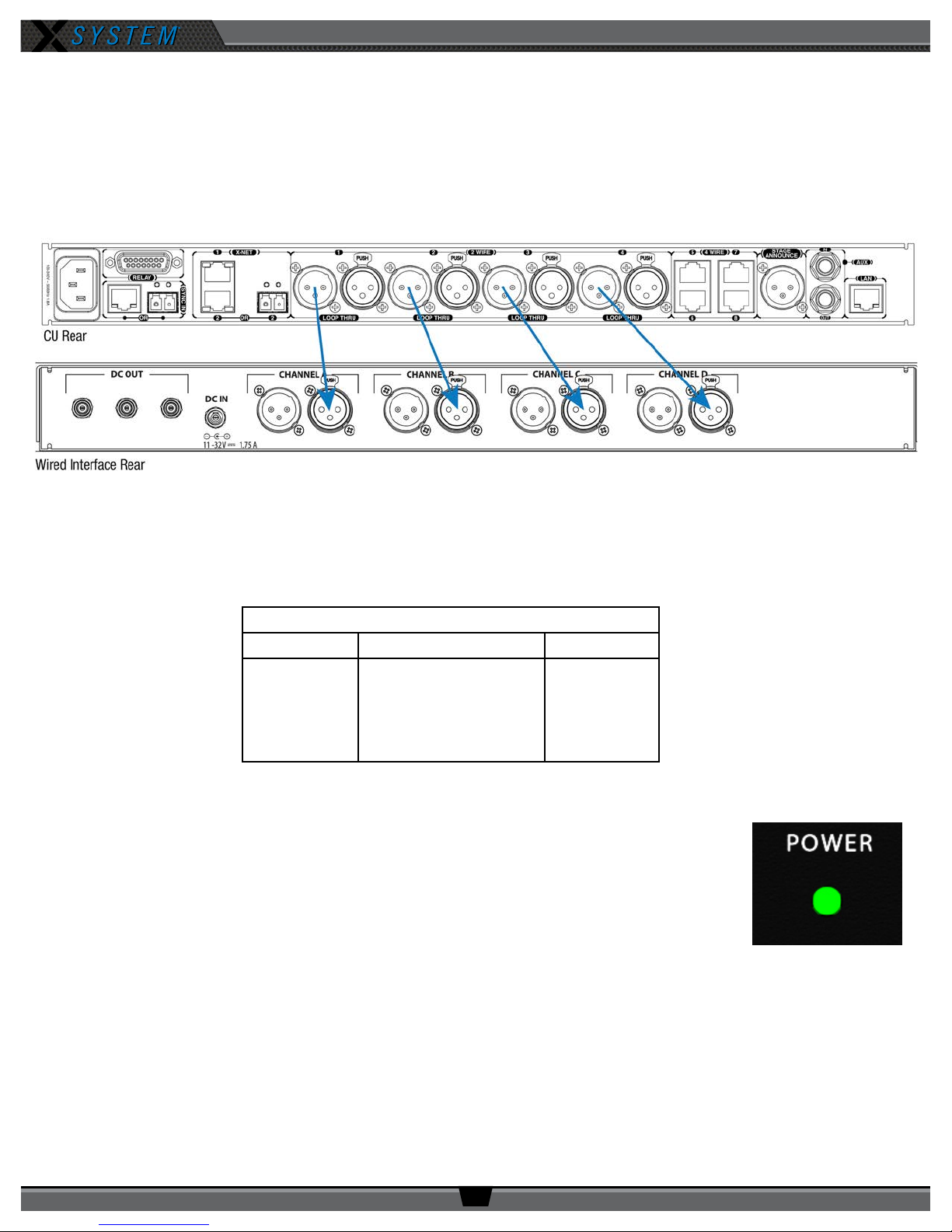
C. Channel A XLRs – Connects Wired Interface Port A to Port 2-Wire 1 of the Control Unit
D. Channel B XLRs – Connects Wired Interface Port B to Port 2-Wire 2 of the Control Unit
E. Channel C XLRs – Connects Wired Interface Port C to Port 2-Wire 3 of the Control Unit
F. Channel D XLRs – Connects Wired Interface Port D to Port 2-Wire 4 of the Control Unit
Note: See the diagram on the next page for more information about these channel ports.
800.749.2761 www.coachcomm.com
11
Page 16
OPERATING MANUAL
A/B and C/D Channel Ports
There are six (6) access ports for channels A/B and C/D on the front of the WI. These ports are for connecting Wired
BeltPacks via a Cat 5 (RJ-45) connection. When connected to these ports, Wired BeltPack can communicate with any
wireless user subscribed to the same channel (also referred to as a conference within X-Ware).
The WI is connected to the Control Unit within the 2RU press box case via four short XLR cables. Figure 13 below shows a
diagram of this connection.
Figure 13: Control Unit and Wired Interface Connection
Default Conferences
An X-System conference is a conversation between a set group of coaches. By default, each X-System will include four
conferences. These four conferences are the only ones accessible to coaches using Wired BeltPacks in the booth.
Table 1: Default Conferences
Wired Port X-System Default Short Name
A Primary Offense Pri O
B Secondary Offense Sec O
C Primary Defense Pri DEF
D Secondary Defense Sec DEF
Wired Interface (WI) Power
There is no power switch on the WI. The power to the WI comes on when it is plugged into an AC
wall outlet. The green “Power” LED on the front of the WI indicates whether power is on or off. The
AC power goes through a DC power supply and then into the “DC IN” of the WI.
Figure 14: Wired Interface Power LED
800.749.2761 www.coachcomm.com
12
Page 17

OPERATING MANUAL
Control Unit (XCU-44)
The X-System Control Unit (CU) is located in the main rack unit in the press box. It serves as the foundation of the wireless
communication system.
Control Unit Front
Figure 15: Control Unit Front View
A. Local Headset Connection – 4-pin XLR male headset connector on the CU’s front panel.
B. Talk Button for Local Headset – The Talk button works in conjunction with the Local Headset Connection. The
Talk button enables or disables the microphone for the local headset. A white “TALK” LED will illuminate when the
mic is enabled.
C. Headset Volume Knob – Turning the Volume control adjusts the listening volume of the local headset. Clockwise
increases the audio level; Counterclockwise decreases the audio level.
D. Wired Intercom Access Button – When pressed, the Control Unit menu jumps directly to the Wired Settings
screen.
E. Radio Packs Button – Shortcut to open the CU’s Radio Packs menu, which allows sorting and selection of Radio
Packs to edit settings (via the CU navigational controls).
F. Local Button – Opens the local headset settings on top of the current screen display, allowing for adjustments to
the local headset settings.
G. LCD Screen – Display for viewing real-time status of system, navigating menus, and making subsequent setting
adjustments. The LCD screen is the focal point of the Control Unit’s functionality. On the Home screen, the LCD
displays the status of all Normal mode Radio Packs that are currently paired to the Control Unit. In the Menu, the
LCD shows the menu items or information.
H. Menu Button – Accesses the main menu system of the CU. The default pass code to access the CU menu is
“0000.” While in the menu system, one short press acts as “Escape” to return to the previous menu without
saving any changes.
I. Home Button – Returns to the Home view when pressed. This also serves as an escape button. (Changes that
may have been in process are not saved if Home is pressed before save is complete.)
J. Navigational Controls – Up, Down, Left, and Right move the cursor or marker on the LCD to make adjustments in
edit mode. Enter (Center) selects the current cursor position or saves the current setting adjustment.
K. USB Micro B – For connectivity to a computer when performing device rmware updates.
L. USB A – For Radio Pack pairing and external USB ash drives.
Note: The CU is currently compatible with FAT and FAT32 formatted USB drives (up to 16 TB drive
size). Some operating systems (e.g., Windows 10) promote NTFS format, but only allow FAT32
formatting up to 32 GB. For hep with formatting larger USB drives, contact CoachComm Customer
Support at 1-800-729-2761.
M. On/Off Switch – Turns the power to the Control Unit on and off.
800.749.2761 www.coachcomm.com
13
Page 18

OPERATING MANUAL
Control Unit Rear
Figure 16: XCU-44 Rear View
A. AC Power Connection – 100–240V, 50/60 Hz 0.8A
B. SYNC IN Port (RJ-45 or Fiber) – Allows the system to be synchronized with another X-System. Sync is
recommended when more than two unsynchronized X-System Antennas are operating in close proximity to one
another.
C. RELAY Connection – Not currently used with X-System operation
D. X-Net Ports (RJ-45 or Fiber) – The X-Net ports allow the Control Unit to connect to other X-System devices,
such as Antennas, forming a proprietary network design where all devices are part of a system conguration that
shares data, timing synchronization, and audio.
E. 2 WIRE Intercom Port (x 4) –The Intercom conference ports (1, 2, 3, and 4) connect the Control Unit to channels
A/B and C/D of the Wired Interface.
F. 4 WIRE Intercom Port (x 4) – Not currently used with X-System operation
G. STAGE ANNOUNCE (SA) – Not currently used with X-System operation
H. Auxiliary Audio Input (AUX IN) – Not currently used with X-System operation
I. Auxiliary Audio Output (AUX OUT) – Not currently used with X-System operation
J. Local Area Network (LAN) Port – The LAN port allows the Control Unit to be connected to a PC and X-Ware. See
the “Connecting X-Ware to Your CU” section on page 32 of this manual for more LAN connection information.
800.749.2761 www.coachcomm.com
14
Page 19
OPERATING MANUAL
Control Unit LCD
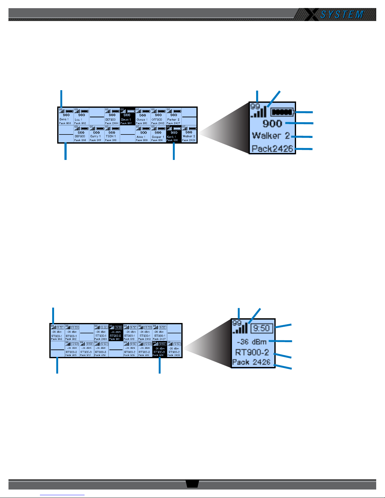
Home Operating Screen
Serves as the primary operating screen and displays the status of the Radio Packs (RPs) connected to the Control Unit.
Active RP
Link Quality
Strength Indicator
Battery Level
Frequency
Prole Name
Pack Name
Radio Signal
No RP Logged In
Note: The Link Quality Indicator (LQ) provides a diagnostic measurement of actual packet transmission from
RP to Antenna and vice versa. The LQ value on the Control Unit LCD represents the lowest LQ value of
the two possibilities. To discover more about which value is displaying on your device, you would need
to consult the individual Radio Pack or X-Ware, if being used. (See Understanding Link Quality on page
29 of this manual for more information.)
Secondary Operating Screen
Displays additional information about the status of the Radio Packs connected to the Control Unit. Short press the Home
button once to toggle between the Primary and Secondary screens. After 60 seconds, the screen will time out and revert
back to the Home screen.
Talk Button is Active
Figure 17: Control Unit Primary Operating Screen
Active RP
No RP Logged In
Note: Radio Signal Strength Value displays the actual value of the radio signal in dBm.
Talk Button is Active
Figure 18: Control Unit Secondary Operating Screen
Link Quality
Strength Indicator
Radio Signal
Remaining Battery
Time
Radio Signal
Strength Value
Antenna Name
Pack Name
800.749.2761 www.coachcomm.com
15
Page 20
OPERATING MANUAL
Control Unit Settings System Conguration Wired Settings Radio Pack Settings
Control Unit Name
LCD Contrast
LCD Backlight
Backlight Time Out
LED Brightness
Long Name
Short Name
Master Sync Priority
Proles
Conferences
View All Conferences
List All Radio Packs
(list model, frequency
band, and mode)
Intercom Settings
Auto Null
Auxiliary Input
Auxiliary Output
Stage Announce
Run Auto Null
View Null Settings
Edit Stage Announce
Audio Level
Enable/Disable Stage
Announce Relay
Assign High Density
Choose Sort Order
Radio Transceivers
Hub
Audio Expansion
Local Headset Conference
Local Headset Mic Gain
Local Headset Mic Type
Local Headset Sidetone
TCP/IP Mode [editable]
TCP/IP Address [editable]
Subnet Mask [editable]
Default Gateway [editable]
MAC Address [non editable]
Diagnostics
Security
Factory Defaults
System Status
Device Status
Device ID
System Timing
Device Timing
Device Temp
Interconnect Length
System Usage
User Rights
Clear Memory and
Restore All
Restore Prole Defaults
Device Settings Local Headset Settings LAN Settings Tech Menu
Control Unit Menu
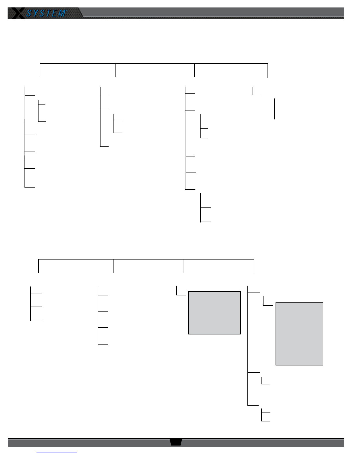
The Control Unit settings can be accessed and adjusted from the Control Unit’s front panel LCD, or, if being used, via the
X-Ware interface on your personal PC. The following menu tree displays the Control Unit’s menu options and settings.
800.749.2761 www.coachcomm.com
16
Page 21
OPERATING MANUAL
Radio Transceiver/Antenna (XRT-ANT-900)
The X-System Radio Transceiver (RT) serves as a point of contact for Radio Packs on X-Net. It should be positioned as high
as possible to provide better and more expanded coverage. An antenna is attached to the front of the RT, and together,
the two devices are known as the “Antenna” throughout other sections of this manual. More information about mounting
Antennas is provided on page 26.
Six Radio Packs may be connected per Antenna.
Radio Transceiver Bottom
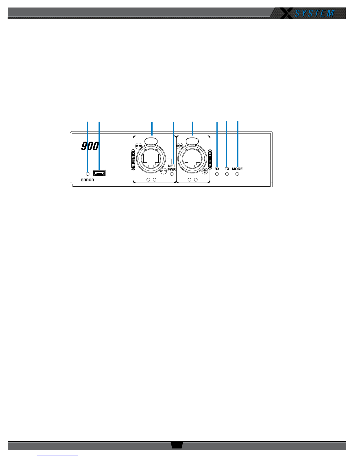
A B C D E F G H
Figure 19: Antenna Bottom View
A. ERROR LED – Indicates the device’s error status.
B. USB Micro B Connection – For connectivity to a PC when performing device rmware updates.
C. X-NET IN Port (RJ-45) and Status LEDs – The Antenna’s X-NET IN ports allow it to connect to any available
X-Net port or RT LOOP port on other devices, adding the RT to a proprietary network where all devices are part of
a system conguration that shares data, timing synchronization, and audio. Each RT has an X-NET IN port (RJ-45)
and an RT LOOP port (RJ-45, which allows RTs to be daisy-chained to one another).
D. Network Power (NET PWR) LED – On when network power is powering the device via connection to the CU.
E. RT LOOP Port and Status LEDs – The RT LOOP port allows you to connect multiple RTs together in a “daisy
chain.”
F. RX LED – Green LED—On when the Antenna is receiving transmissions from Radio Packs. This LED will blink
briey when a Radio Pack rst logs in to the Antenna and then return to normal operation.
G. TX LED – Green LED—On (blinking rapidly) when the Antenna is transmitting properly.
H. MODE LED – Green LED—On when set to Normal Mode.
800.749.2761 www.coachcomm.com
17
Page 22
OPERATING MANUAL
AB
G H
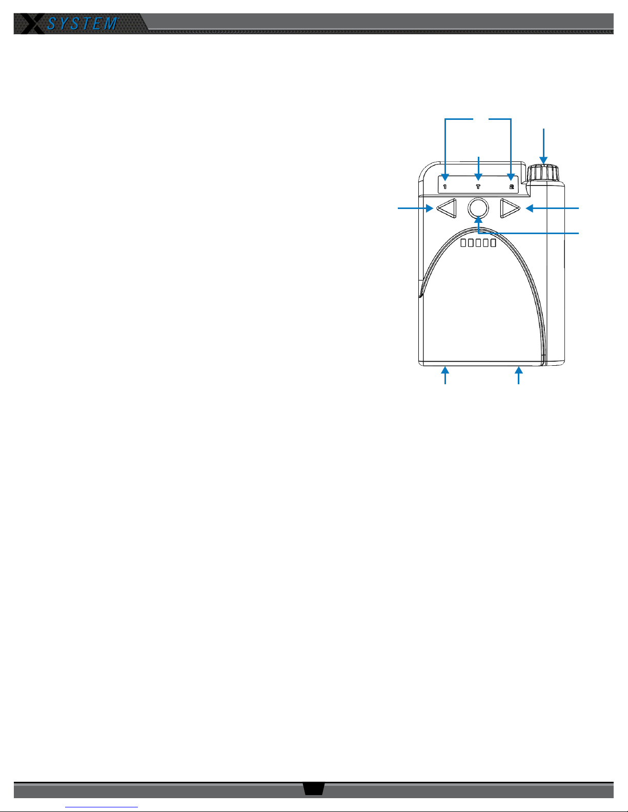
Wired BeltPacks (X-WBP2-01)
The X-System Wired BeltPack is to be used in the press box, connecting to the Wired Interface.
A. On/Off/Volume Control
functions. First, it is the On/Off switch for the BeltPack. To turn on
the BeltPack, turn the knob clockwise and watch for the LEDs on
the front to come on. To turn the BeltPack off, turn the knob in a
counterclockwise direction until you feel a click. All of the lights on
the BeltPack should go off and you should not hear any audio in the
headset. The control knob also allows you to adjust the audio level
in your headset.
B. Channel 1 and 2 LEDs (Blue)
C. Talk LED (Green)
D. Channel 1 Button – The Channel Buttons set the BeltPack to that
communication channel (indicated with blue “1” or “2” LEDs above
each button). Channel “1” on the Wired BeltPack will correspond
to either channel “A” or “C” of the Wired Interface, depending
on where the unit is connected. The Wired BeltPack’s channellock feature allows coaches to be locked on a single channel, as
opposed to having access to both channels. To enable this feature,
hold down the channel button you want to lock while powering on
the BeltPack.
– The On/Off/Volume Control knob on top of the Wired BeltPack serves two main
D
C
E
F
E. Channel 2 Button – The Channel Buttons set the BeltPack
to that communication channel (indicated with blue “1” or
“2” LEDs above each button). Channel “2” of the Wired BeltPack
will correspond to either channel “B” or “D.” The Wired BeltPack now offers a channel-lock feature that allows
coaches to be locked on a single channel as opposed to having access to both channels.
Note: Only coaches who are on the same communication channel (A/B/C/D) will be able to hear each other.
For more information about the conferences (channels) accessible to coaches with Wired BeltPacks
see page 12.
F. TALK Button – The TALK button toggles the microphone of the headset on or off. The Talk LED, which is located
directly above the TALK button, will light green whenever the microphone is on. When the Talk LED is on, anything
you say into the headset microphone will be communicated to all other coaches on the system that are on the
same channel to which your BeltPack is set. You can push the TALK Button to turn on the Talk LED and forget it, or
you can use it as a momentary mute function to have off-line conversations during the game.
G. Headset Connector (Bottom)
the bottom of the BeltPack. Push the headset connector all the way into the bottom of the BeltPack until you hear a
click. Do not force the connector. The audio level will vary depending on the type of headset used.
H. Wired BeltPack RJ-45 Connector (Bottom)
– The headset is connected to your Wired BeltPack via the 4-pin XLR connector on
Figure 20: X-WBP2-01 Wired BeltPack
800.749.2761 www.coachcomm.com
18
Page 23
OPERATING MANUAL
Radio Packs (XRP-13)
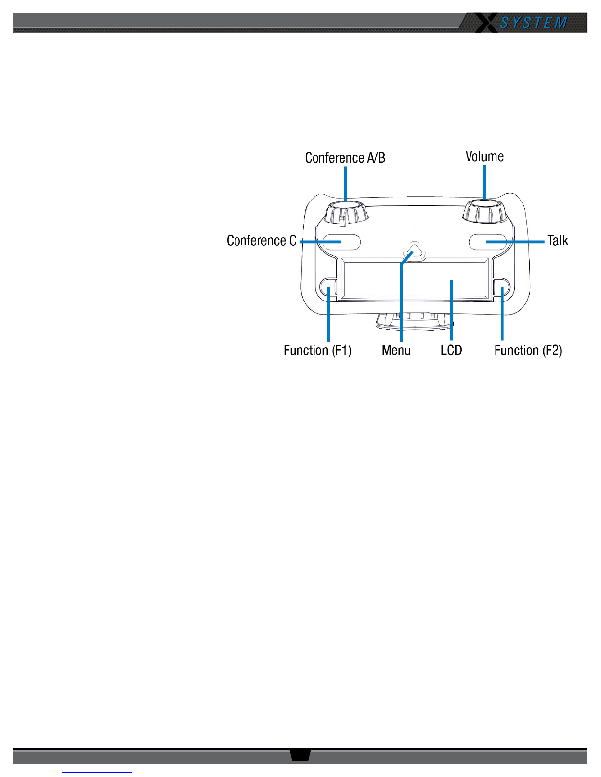
The X-System Radio Pack (RP) is to be worn by a user on the sideline or the press box who needs a wireless pack. The RP
communicates directly to its corresponding Antenna. All wireless users are connected together through the wired system
via the Control Unit.
Radio Pack Top
• Conference A/B Rocker Knob
– The Conference A/B knob
selects whether you are listening
to your RP prole’s assigned
conference A or conference B.
• Conference C Button
– The
Conference C Button enables
or disables the audio for the RP
prole’s assigned conference C.
• Volume Knob – The Volume
control adjusts the listening
volume of the connected
headset for the selected
conference. Turning the Volume
control clockwise increases
the audio level, while turning
Figure 21: XRP-13 Top View
the control counterclockwise
decreases the level.
• Talk Button – The Talk button enables or disables the microphone for the selected conference. Talk buttons can
be set to function as “Latch” press, “Momentary” press, “Always On” or “Always Off.” In addition, X-System
uses an intelligent latching method for Talk buttons. When set to “Latch,” one short press will latch the Talk on;
however, pressing and holding the Talk button will cause the button to act as a momentary switch.
• Function Buttons (F1/F2) – The left (F1) and right (F2) function buttons can be programmed to assign a variety
of functions. Each Function button’s operation is set in the RP’s prole, which can be customized if using X-Ware.
While in the menu, one short press of F1 returns you to the previous menu without saving any changes, and F2 is
used to select a highlighted menu option.
• Menu Button – The Menu button provides multiple functions such as access to menu options or toggling between
the home operating screen and the secondary operating screen.
» Short Press – Cycles the RP LCD from the Home Operating screen to the Secondary Operating screen and vice
versa.
» Long Press – Accesses the menu options of the RP to view device/system information and make setting
adjustments.
» Escape – While in the menu, one short press returns you to the previous menu without saving any changes.
• LCD – Display for viewing real-time status of the RP, navigating menu options, and making subsequent setting
adjustments.
800.749.2761 www.coachcomm.com
19
Page 24
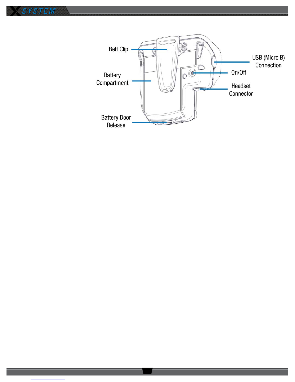
Radio Pack Rear
• Belt Clip – Secure and
sturdy belt clip enables
RP wearing via belt.
• Battery Compartment
Door – Secures and
protects the RP’s LithiumPolymer battery or 3 AA
batteries.
• Battery Door Release
– Pressing the release
opens the RP’s battery
compartment.
• USB (Micro B)
Connection – This
USB connection is for
connecting an RP to a
Control Unit for pairing or connecting an RP to a PC for device rmware updates.
OPERATING MANUAL
Figure 22: Radio Pack Rear View
• On/Off Button – The On/Off button powers the RP on and off when pressed for 3 seconds.
• 4-Pin Male XLR Headset Connector – Headset connector is a 4-pin male XLR connection. Optional XLR adapters
(4-pin female to 4-pin female and 4-pin female to 5-pin female) are sold separately.
800.749.2761 www.coachcomm.com
20
Page 25
OPERATING MANUAL
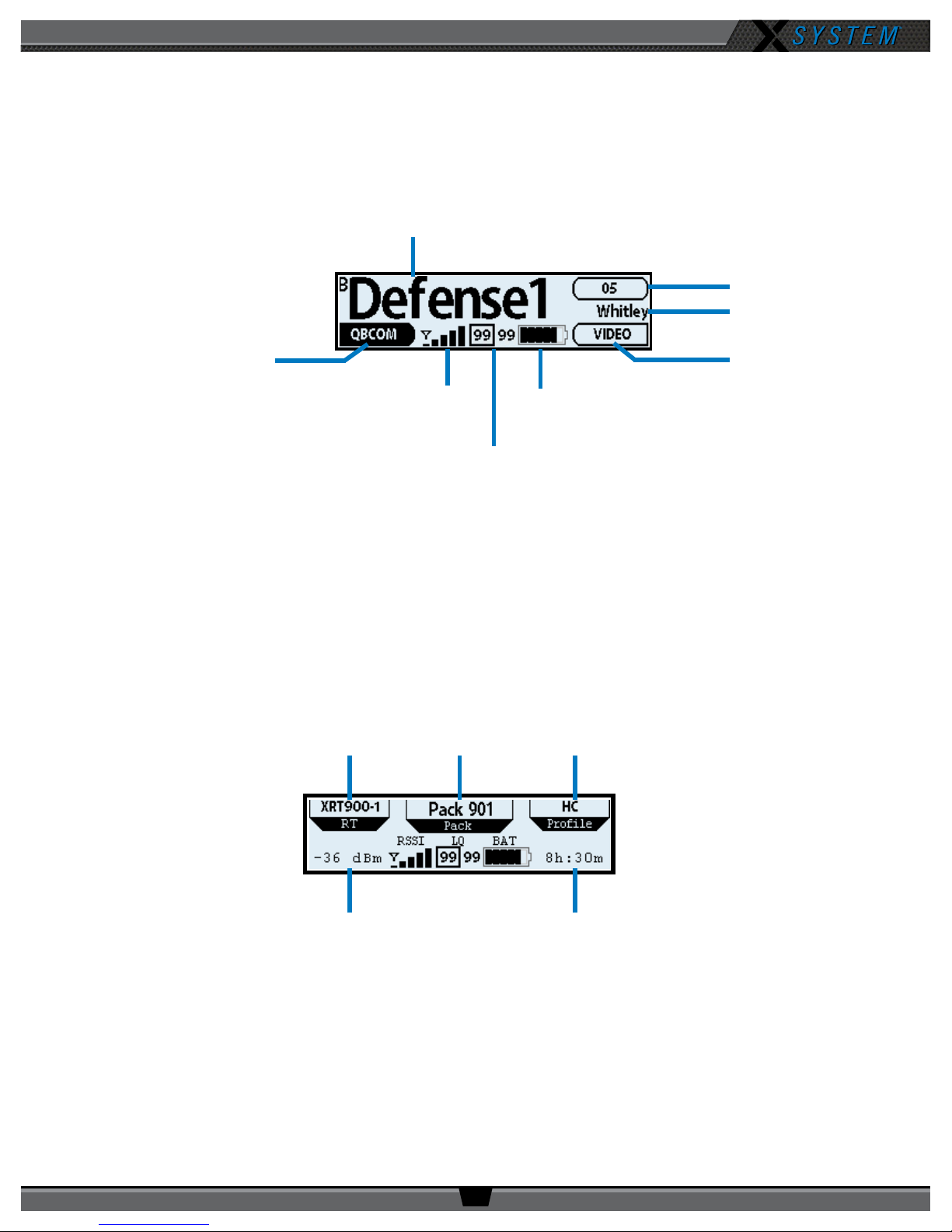
RT Name Pack Name Prole Name
Radio Pack LCD
Home Operating Screen
Serves as the main operating screen and displays the status of the Radio Pack (RP) as well as talk, volume, and function
assignments.
Active Conference
Volume Level
Prole Name
F1 Assignment
Radio Signal
Battery Level
F2 Assignment
Strength Indicator
Link Quality
Figure 23: RP-44 Home Operating Screen
Note: The Link Quality Indicator (LQ) provides a diagnostic measurement of actual packet transmission from
RP to Antenna and vice versa. The outlined LQ represents the Antenna’s LQ. (See Understanding Link
Quality on page 29 of this manual for more information.)
Secondary Operating Screen
Serves as a secondary operating screen and displays additional information about the status of the Radio Pack. Short press
the Menu button once to toggle between the Home and Secondary screens. After 60 seconds, the screen will time out and
revert back to the Home screen.
Radio Signal
Remaining Battery Time
Strength Value
Figure 24: RP Secondary Operating Screen Overview
Note: Radio Signal Strength Value displays the actual value of the radio signal in dBm.
800.749.2761 www.coachcomm.com
21
Page 26
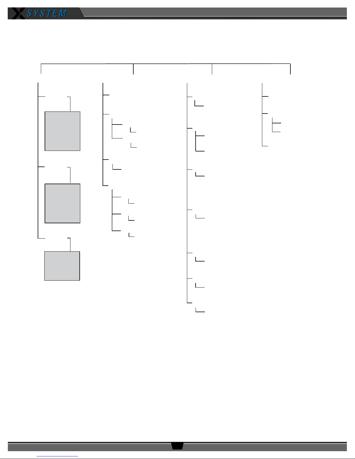
OPERATING MANUAL
Pack Info Device Settings User Settings Tech Menu
Page 1
Page 2
Page 3
Model
Prole
Mode
Serial Number
Firmware Revision
Transceiver
Mic Type
Mic Gain
Auto Detect
Dynamic
Electret
Dynamic Mic Detected:
0 (+6dB) to 10 (+35 dB)
Factory Defaults
Restore Defaults
Clear Memory
Mic Type
Mic Gain
Noise Gate
Contrast
Backlight Brightness
Backlight Time Out
Side Tone
Talk Tones
Volume Min
Volume Max
Edit Backlight Time Out
Backlight Timeout
Edit Backlight Brightness
Backlight Brightness
Edit Contrast
Contrast
Display Options
Edit Battery Alert
Battery Alert
Short Name
Pack Name
Long Name
Edit Short Name
Edit Long Name
Noise Gate
Very High -48 dB
High -57 dB
Medium -66 dB
Low -75 dB
Disabled
Sidetone
Very High -0dB
High -6 dB
Medium -12 dB
Low -18 dB
Very Low -24 dB
Min Volume
0 (-57 dB) to 19 (+3 dB)
Max Volume
1 (-53 dB) to 20 (+6 dB)
Talk Tones
On
Off
Electret Mic Detected:
0 (-12 dB) to 10 (+17 dB)
Tech Info
Pack Proles
Diagnostics
Radio Pack Menu
Radio Pack settings can be accessed and adjusted from the RP’s LCD, the Control Unit’s LCD, or, if being used, via the
X-Ware interface on the touch screen monitor. The following menu tree displays all of the RP’s menu options and settings:
800.749.2761 www.coachcomm.com
22
Page 27
OPERATING MANUAL
Charging Radio Pack Batteries
Radio Packs are powered with (1) Lithium-Polymer rechargeable battery for greater than 9 hours (900MHz), or they may be
powered with (3) AA Alkaline batteries for approximately 4.5 hours (900MHz).
The batteries can be charged either inside the RP with an external power supply or by using the 5-Bay rapid charger.
The batteries require approximately 3 hours to charge from empty. Take care to insert the battery into the RP with the
contacts facing down and oriented such that the contacts on the battery will line up with the contacts inside the RP battery
compartment.
To charge the RP, connect the plug-in battery charger (included with RP) to a standard wall outlet and to the Micro-USB
connector on the RP. The connector is located under the rubberized access cover on the side of the RP. The battery may also
be charged inside the RP via the USB port of a computer.
Up to ve (5) CoachComm lithium-polymer batteries may be charged at the same time using the 5-Bay charger. If charger(s)
overheats, it will need to be moved to a cooler area to charge batteries properly. As a lithium-polymer battery safety
mechanism, the battery chargers include a safety circuit, which prevents charging of batteries if the ambient temperature is
too hot. For the batteries to charge in the 5-Bay charger, there must be external AC power.
If using three (3) AA batteries, CoachComm recommends that only major brand, standard batteries should be used for
maximum reliability and effectiveness. You should expect approximately 4.5 hours (900MHz) of operation using new AA
batteries.
There are several considerations you should take into account when using AA batteries. The RP’s battery level and
remaining battery time indicators only reect battery life for lithium-polymer batteries; therefore, those screen options will
not be used when AA batteries are in use. In cold weather, AA batteries do not release their stored energy completely, so
the result is a dramatic reduction in operation time. It would not be uncommon to have an AA battery only last 50% of its
original life when used in very cold situations. Also, remove the AA batteries when not in use to avoid potential damage from
leaking battery acid that can sometimes occur in these type batteries.
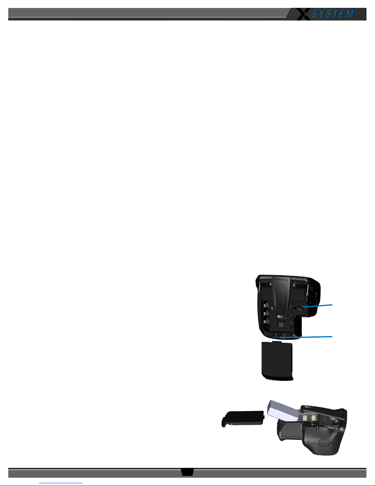
Installing a Radio Pack Battery
1. Before powering on an RP, install its battery by doing the following:
A. Press the battery-release button on the rear of the battery pack to
unlatch the battery door.
B. Depress the RP’s belt clip to access and remove the battery door.
C. Install a fully charged Lithium-Polymer rechargeable battery or
three AA batteries into the RP. Then, place battery door back on
the RP.
2. Turn on the RP by pressing and holding the Power button on the back
of the pack for 3 seconds.
Note: The RP will not operate unless it has been paired to a Control
Unit; if it has not been paired it will indicate “No Pairing
Information Available” on the pack’s display.
Figure 25: Rear View of RP’s Power Button and Battery Door
Power
Button
Battery
Door
Release
Figure 26: Radio Pack Battery Installation
800.749.2761 www.coachcomm.com
23
Page 28
OPERATING MANUAL
Pairing an RP to a Control Unit
Note: New systems are congured and paired at the manufacturer. The following procedures may not be
required initially if your system was congured at the manufacturer.
RPs must be paired to the Control Unit (CU) before they can operate with your X-System. Once RPs are paired to the CU,
this process does not need to be done again unless the RP is being paired to a new or different CU (for example, after a
replacement is made for repairs). An RP may be paired without installing a battery, if required. In this case, the CU will
provide power to the RP during the pairing process. If no battery is installed, the RP will power down as soon as it is
disconnected from the CU.
To pair your RP, use the following steps. While pairing, do not disconnect the RP until you are instructed to do so.
1. Connect the Antenna(s) (on the mounting bracket) to the Press Box Rack Unit’s rear panel. Then, power on the
CU.
2. Ensure the RP to be paired is powered off.
3. Connect a USB-to-Micro-USB cable from the CU to the device (micro end goes into the RP’s USB port beneath its
rubber port cover). The RP will power on by itself.
4. Follow the prompts displayed on the RP. You will need to use the RP volume knob and function buttons to choose a
prole from those available in the list on the RP’s LCD.
5. Wait for the prole to load. The LCD will display a “Pairing Complete” message when the prole is nished
loading.
6. Disconnect the USB cable from the device. The RP will power down automatically when disconnected.
7. Power on the RP and wait for it to log in to the system. The initial login may take up to 1.5 minutes.
When an RP is logged in, its RSSI indicator will display on the primary LCD screen.
8. If using X-Ware, you can verify that the RP paired correctly and is displayed in X-Ware. You may need
to refresh the X-Ware display by touching the grid button on the right-hand side.
9. The RP is ready for use. Repeat these steps until every RP is paired.
Figure 27: X-Ware
Grid Button
800.749.2761 www.coachcomm.com
24
Page 29
OPERATING MANUAL
System Accessories
Press Box Cables
Wired users are connected to the X-System via press box cables. Press box cables are the bundled Cat 6 cables that
connect the Wired BeltPacks to the Wired Interface.
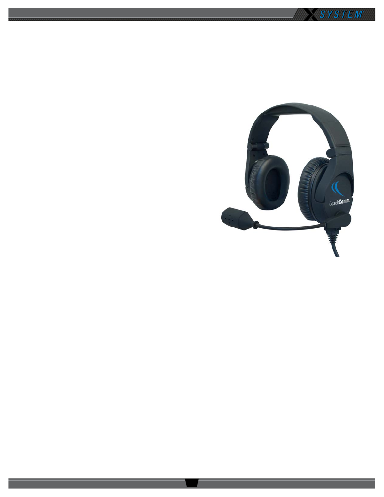
Headsets
CoachComm now offers exclusively the SmartBoom® series of
headsets. The SmartBoom technology enables you to effortlessly
mute your microphone by simply raising the boom above your
brow. Re-enable the microphone by lowering back to the mouth. All
headsets have a 4-pin XLR connector.
Figure 28: SBP-152, Dual Ear Model SmartBoom PRO Headset
800.749.2761 www.coachcomm.com
25
Page 30
OPERATING MANUAL
System Setup and Operation
Mounting Antennas
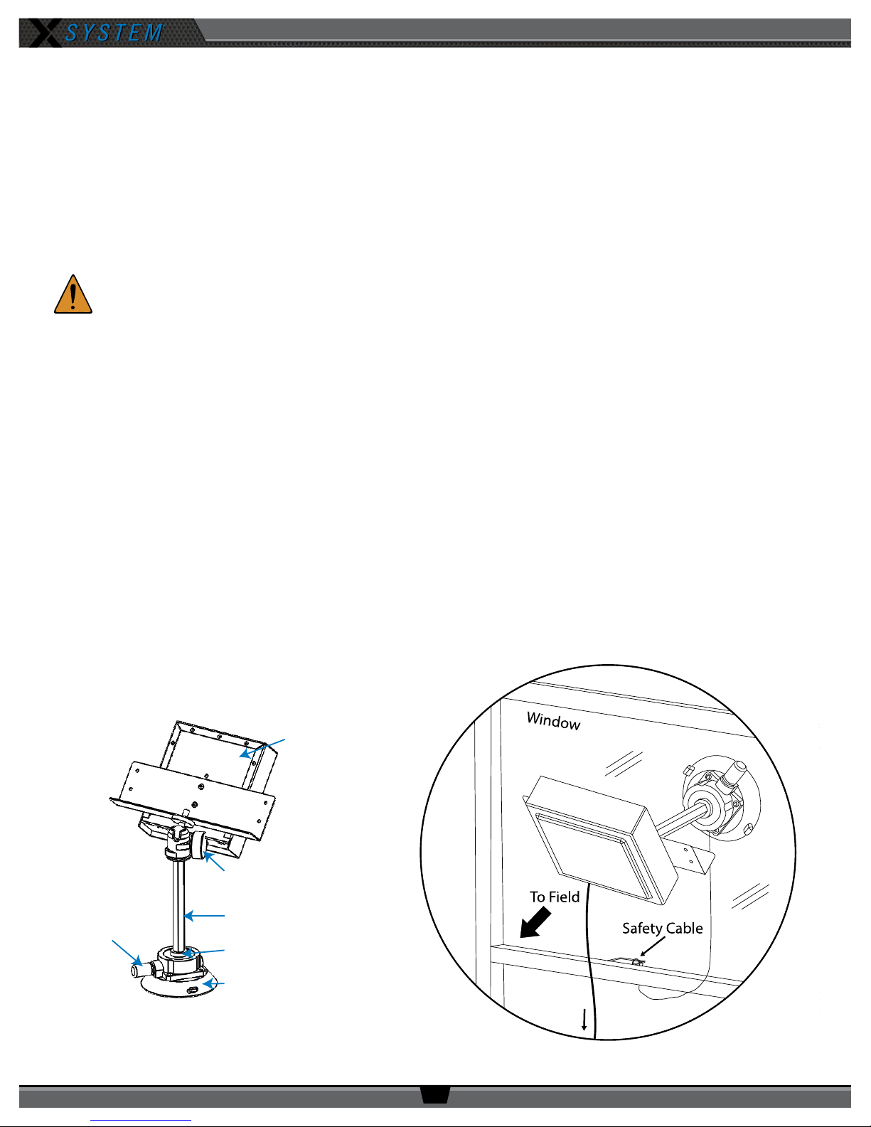
Your eld Antenna is located in the press box case under the Press Box Rack Unit, along with its mounting hardware. You
have two options when mounting your Antenna: using the suction cup or the super clamp. Setup instructions for each type
of mount are provided below.
Important!
CAUTION: Failure to comply with the following may result in equipment damage, damage to surface
Use only approved Antennas to avoid possible FCC violations! The Antenna mounted to the
XRT-ANT-900 is not user replaceable.
area, or personal injury.
Using the Suction Cup
1. Loosen the ball mount knob so the hex standoff can rotate.
2. Twist the Antenna’s hex standoff onto the top of the suction cup’s stud, securely tightening it. Then, re-tighten
the ball mount knob.
3. Attach the suction cup’s safety cable to a xed object.
4. Press the suction cup to a dry, at surface, such as a table or a glass window.
CAUTION: Attempting to secure the suction cup to a moist or textured surface may cause malfunction,
which could result in damage to equipment, persons, or property below mounting area.
5. Press the pump button until the red line on its side is no longer visible.
6. Point the front of the Antenna toward the center of your team’s coaches’ box. (Loosen the ball mount knob to
adjust the angle of the Antenna, if needed.)
7. Connect a Cat 5 cable to the X-NET IN port on the Antenna. Connect the other end of the Cat 5 cable to the FIELD
ANTENNA port on the Press Box Rack Unit’s rear panel.
RT Rear
Ball Mount Knob
Hex Standoff
Pump Button
Stud
Suction Cup
Figure 29: Single-Mounted RT with Suction Cup
800.749.2761 www.coachcomm.com
26
To Press Box
Rack Unit
Figure 30: Window-Mounted RT
Page 31
OPERATING MANUAL
50 4040
5040 40
50 4040
5040 40
Your Sideline
Your Sideline
OR
Large Screw
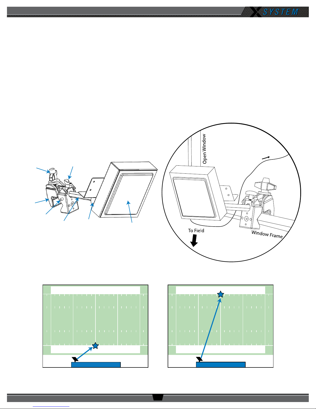
Using the Super Clamp
1. Loosen the clamp’s small screw.
2. Press the clamp’s side button as you insert the Antenna’s hex standoff into the opening and tighten it. Release the
button once the standoff is fully seated.
3. Tighten the clamp’s small screw.
4. Fasten the clamp to the desired location, such as a railing or the side of a table, using the clamp’s larger screw to
loosen and tighten it.
5. Point the front of the Antenna toward the center of your team’s coaches’ box. (Loosen the ball mount knob to
adjust the angle of the Antenna, if needed.)
6. Connect a Cat 5 cable to the X-NET IN port on the Antenna. Connect the other end of the Cat 5 cable to the FIELD
ANTENNA(S) port on the Press Box Rack Unit’s rear panel.
To Press Box
Small Screw
Rack Unit
Clamp
Side Button
Hex
Standoff
Figure 31: Single-Mounted RT with Clamp
Ball Mount
Knob
RT Front
Figure 32: Clamp-Mounted RT
Figure 33: Center of Your Coaches’ Box
800.749.2761 www.coachcomm.com
27
Page 32
OPERATING MANUAL
Dual Antenna Systems
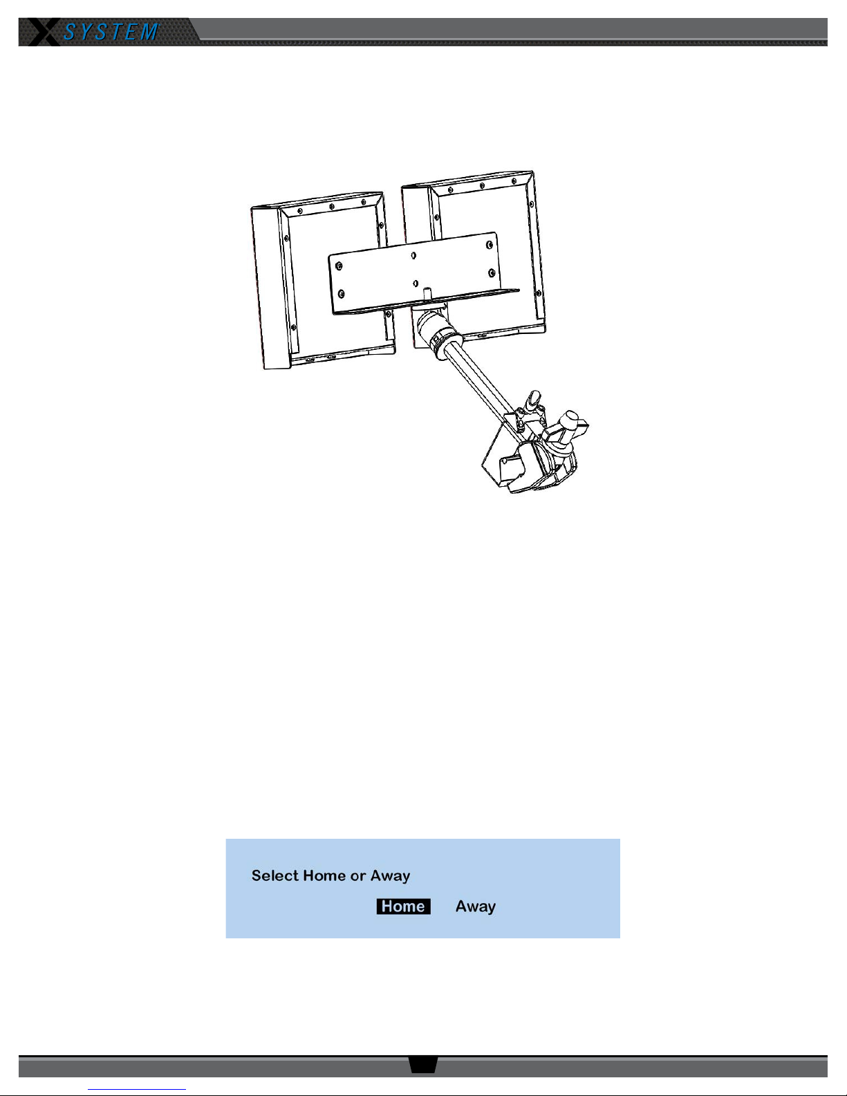
Some customers may use a dual-Antenna system. In that instance, two Antennas are mounted together on the same
bracket, and the suction cup and the super clamp function the same way as detailed on the previous pages.
Figure 34: Dual-Mounted Antenna
Covering Your Antennas
When using your Antennas in a wet environment, protect them with a protective enclosure that will not interfere with the RF
(for example, a clear plastic bag). CoachComm recommends either covering each Antenna individually with small bags or
covering the whole bracket with a large bag. The X-System Antennas are weather-resistant, including gaskets intended to
prevent moisture entry from the top and sides. The cable connections on the bottom are not water tight.
Setting Home/Away Status
When you power up the X-System, a prompt for selecting “Home” or “Away” displays on the Control Unit (CU) LCD. Based
on this setting, all of the Antennas on the system will be assigned specic hopping patterns by the CU. A selection must be
made before you can proceed with system setup.
It is very important to set this status correctly. Hopping pattern coordination prevents interference between X-Systems. After
selecting either Home or Away, wait until the CU displays the following message: “CCF Loaded” along with a conguration
le summary. Once the message times out, the home screen will display on the front of the CU.
Figure 35: Control Unit Home/Away Status Prompt
800.749.2761 www.coachcomm.com
28
Page 33
OPERATING MANUAL
RP to Antenna
Antenna to RP
Walk Testing Your System
Walk testing is very important. If a user only tests the Radio Packs (RPs) while standing still, he may not discover potential
frequency problems. Follow the steps below to properly walk test your RPs:
1. On the sideline, unpack the sideline case and install one of the provided, fully charged Lithium-Polymer
rechargeable batteries or three AA batteries in each RP.
2. Power on the rst two RPs by pressing and holding the Power button on the back of each RP for 3 seconds.
3. Conrm each RP is on the same conference, connect a headset to each RP, and conduct a walk test to conrm
their operation. The RP’s LQ value can be used to gauge performance. See the following section for more
information about LQ values.
Important: Each tester should walk their RPs to opposite goal lines and back, ensuring clear
communication between all RPs. Always place the RP on the hip opposite from the press box
when walk testing.
4. After walk testing is complete, mute the RP by either turning the Talk button off or raising the SmartBoom PRO
mic, then place the RP down on a table or bench. Be sure to place each RP a foot or so apart; bunching RPs
together could impact wireless performance.
Important: If raining, cover the RPs or return them to their cases.
5. Repeat steps 2–4 for each of the remaining RPs.
6. Conrm communication between RPs and Wired BeltPacks.
Understanding Link Quality
The Link Quality (LQ) is a numeric value that provides a real-time metric on the quality of communication between the radio
in the Antenna and the radio in the RP. The LQ serves as a diagnostic tool for proper system operation and troubleshooting
RPs.
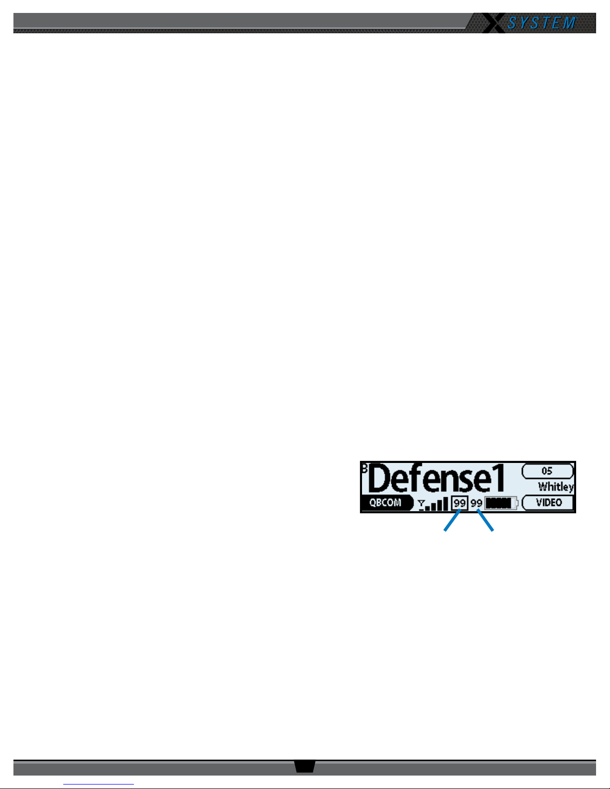
• With X-System, the receiving LQ signal is reported for both
the Antenna and RP. The RP’s on-screen LQ indicator with
the box around it is the Antenna’s LQ from the RP. If this
LQ is lower than normal, then it is an indication that you
may have an issue related to interference, the Antenna, or
a cable connection. If only the RP’s LQ is low, it could be an
indication that you may have an issue related to interference
or the RP.
• What should the LQ value be during operation? — There
is no exact value that LQ will remain at during system
operation. Depending on what degree of outside interference or attenuation (blocking) is present, the LQ will
uctuate during normal operation. Fluctuations in LQ can and will span a wide range of values. The lower the
LQ, the poorer the audio quality will be during operation. During start-up, within adequate range and no outside
inuences present, the LQ should display “99” which is the highest LQ value a RP or Antenna can have.
Link Quality
Figure 36: RP Primary Screen LQ Indicator
Link Quality
• What if the LQ on a single RP is below “99” at start-up? — This depends on where the RP is located at startup, but if the other RPs on the same Antenna are at “99” this is a good indication that isolated radio issue exists
within that RP. If the LQ value has dropped considerably lower or if that unit is experiencing poor audio quality it
may require service.
800.749.2761 www.coachcomm.com
29
Page 34
OPERATING MANUAL
X-Ware Setup and Installation
X-Ware is X-System’s proprietary intercom management software, and its easy-to-use game day interface provides
fast access to critical information and settings, allowing efcient management of large systems. Within X-Ware, you can
manage user settings, set up and manage proles, and access system diagnostics.
X-Ware is not required for system operation; it is an optional tool to assist in real-time monitoring and changing of
X-System settings. If you would like to install X-Ware on a PC to use with your system, your PC will need to meet the
following system requirements:
System Requirements
• Windows 7 or higher
• 4 GB system memory
• Windows Experience Index for Graphics 5.9
• .NET version 4.5
• When using X-Ware with any kind of Windows application, be sure to make an exception for X-Ware in the
Windows rewall.
Additional Recommendations
• XGA video screen; 1024 × 768 or greater resolution
Installing X-Ware
A copy of X-Ware is available on the USB drive included with your X-System. Use the following steps to install X-Ware on a
compatible PC:
Note: If you are installing an updated version of X-Ware, you’ll need to rst delete the previous version from
your computer prior to opening the “XWare_Setup.exe” le. See page 44 for procedures to uninstall X-Ware.
1. Locate the “XWare_Setup.exe” le on the USB drive included with your X-System.
2. Double-click and run the setup le.
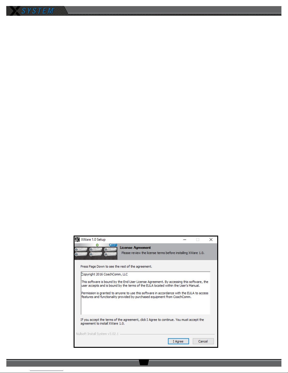
3. On the License Agreement screen, click
I Agree.
Figure 37: License Agreement Screen
800.749.2761 www.coachcomm.com
30
Page 35
OPERATING MANUAL
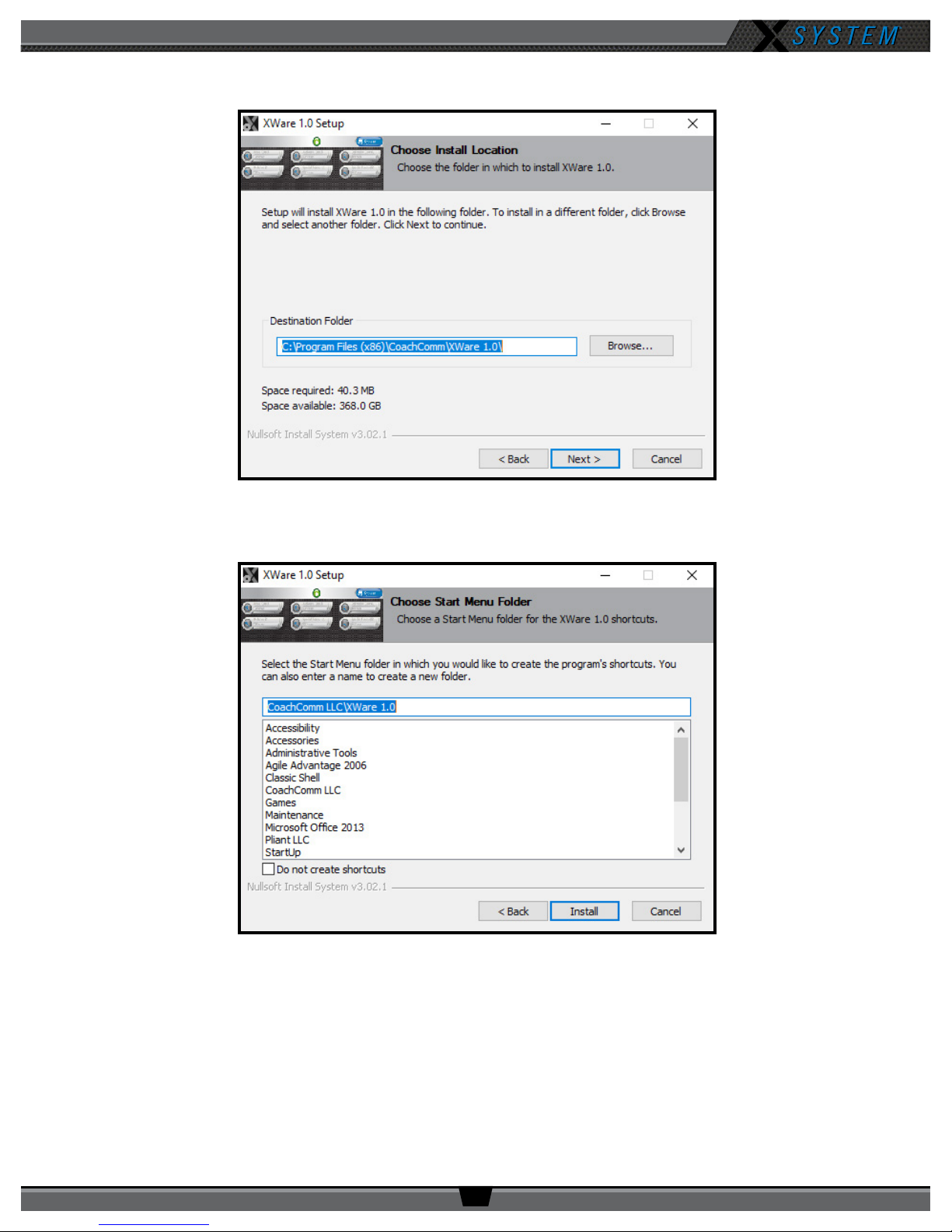
4. On “Install Location” screen, click
Figure 38: Default X-Ware Destination
Next
5. On the “Start Menu Folder” screen, click
few seconds. Click
Close
when complete.
to install X-Ware into the default destination folder.
Install
to begin install. The installation process will begin and take only a
Figure 39: X-Ware Shortcut Folder Selection
6. An X-Ware icon will now be located on your PC’s desktop, and the program is ready for use.
800.749.2761 www.coachcomm.com
31
Page 36
OPERATING MANUAL
Connecting X-Ware to Your CU
Follow the steps below to connect your X-System to your PC so that you can use X-Ware on game day as a real-time
monitoring tool.
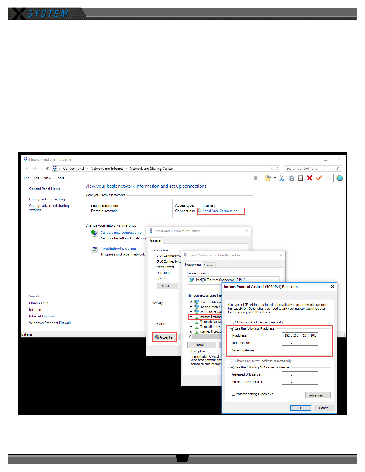
1. Right-click your PC’s connection icon and select
window from your PC’s Control Panel.)
2. Click
Local Area Connection
near the upper right of the window. The Local Area Connection Status window will
display.
3. Click
4. Double-click the
Properties
. A Local Area Connection Properties window will display.
Internal Protocol Version 4 (TCP/IPv4)
Properties window will display.
5. Click the radio button beside
Use the following IP Address
Open Network and Sharing Center.
option from the list of connection properties. A TCP/IPv4
, then type
192.168.10.99
(Or access the same
in the eld. Click
OK.
Figure 40: Changing PC IP Address
800.749.2761 www.coachcomm.com
32
Page 37
OPERATING MANUAL
6. Connect a Cat 5 cable from your PC to the LAN port on the rear of the X-System CU (in the Press Box Rack Unit.)
See page 14 for a diagram of the CU rear and the location of the LAN port.
7. Complete the procedures detailed in the Game Day
Setup section on page 5 of this manual.
8. Double-click on the X-Ware icon on your desktop to
open X-Ware. X-Ware will open and connect to the CU,
and you will be able to view the real-time status of all
connected and paired X-System devices from X-Ware.
See page 34 for more information about X-Ware
Operation.
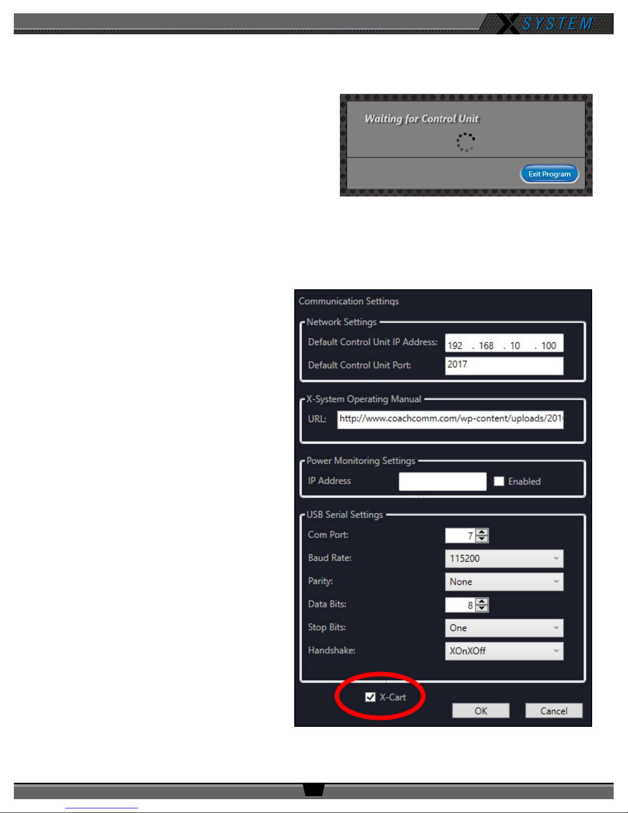
Figure 41: Waiting for Control Unit X-Ware Screen
Note: If X-Ware is not connected to your CU or if the CU
is not powered on, you will see the following message when you open the game day interface of
X-Ware: “Waiting for Control Unit.”
Enabling Game Day Interface
Sometimes Windows 10 PCs open X-Ware to the
Advanced Settings interface instead of the Game Day
Interface depicted in Figure 43 on page 34.
To modify X-Ware’s startup behavior to show the Game
Day Interface when opened, follow the steps below:
1. Right-click the X-Ware icon on your PC’s
desktop and choose
2. Once X-Ware is open, click
Conguration
Settings
. A dialog box will display.
3. Click the checkbox beside
OK
.
Run as Administrator
Edit,
, then
Communication
X-Cart
then
, then click
.
4. Close X-Ware. The next time you open X-Ware,
the game day interface will display.
Figure 42: Checkbox to Enable X-Ware Game Day Interface
800.749.2761 www.coachcomm.com
33
Page 38
OPERATING MANUAL
A B C D
E
F G
X-Ware Operation
Home Screen
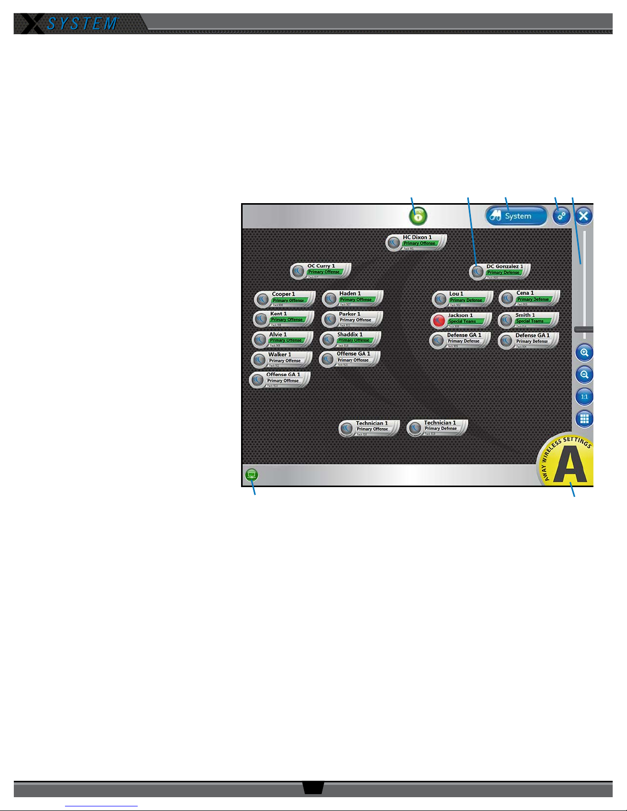
When X-Ware opens, the Home screen displays an overview of icons that represent all Radio Packs (RPs) on the system and
their current status on the system. This is the default screen that displays during game time, and it is often referred to as
the “game day interface.” If this screen does not display when you open X-Ware, you may need to enable the game day
interface (see page 33 for more details about this procedure).
A. Lock-Out Button – Locks X-Ware.
This prevents unauthorized
access.
B. RP Icon – Contains the Prole
Name, Active Conference,
Pack Name, and a color-coded
status indicator. The icons can
be positioned to your liking by
dragging them to a location on the
screen.
C. System Button – Opens X-Ware’s
additional RT (Antenna), RP, and
Conference views.
D. Advanced Settings Button –
X-Ware’s Advanced Settings
interface is where the core
operational settings for the system
conguration reside. Changes to
these settings can impact system
performance if made improperly.
In particular, changes to these
settings during “live” operation on
game day should be avoided. It is
highly recommended you contact CoachComm Customer Support prior to game day if changes are desired.
E. Zoom – Slider bar and other view options allow you to adjust the magnication of the Home Screen view.
F. CU Connection Indicator – Green illumination of this indicator conrms that the Control Unit (CU) and X-Ware are
connected and communicating. When not illuminated, an “X” will appear in the indicator meaning the CU is not
connected to X-Ware.
G. “Away” Indicator – If your system is set as the “Away” team, a yellow Away indicator will display in the bottom
right-hand corner of the Home screen. If your system is set as the “Home” team, no icon will display.
Figure 43: X-Ware Home Screen
800.749.2761 www.coachcomm.com
34
Page 39
OPERATING MANUAL
Prole Screen
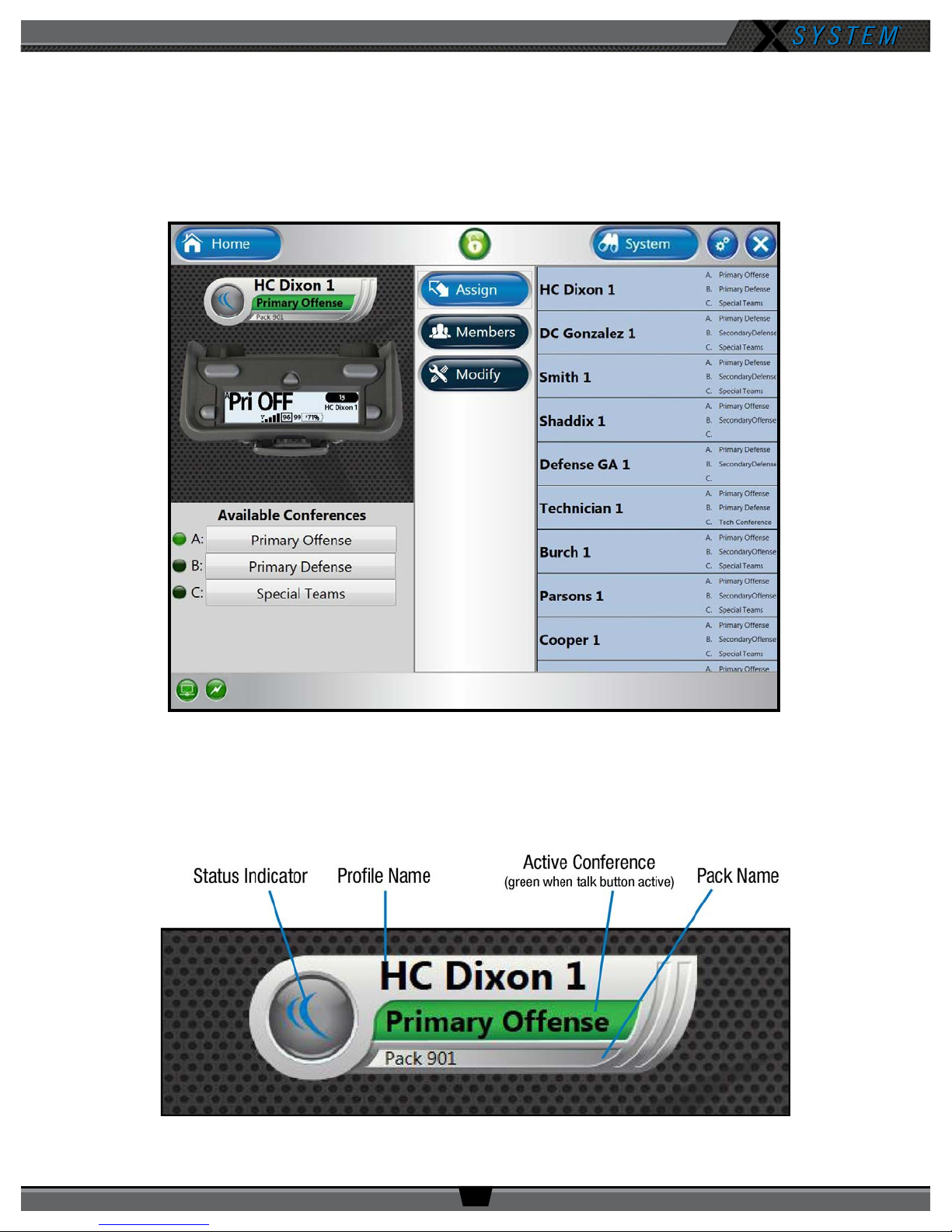
Access the RP Prole screen from the System button or by tapping/clicking on a particular RP icon from the Home screen.
This view provides details about the selected RP, including a “live” view of that RP’s real-time display and available
conferences. From this screen, you can view the RP status, assign conferences, assign a new prole, view conference
members, and show the RP user’s accessibility to other members.
Figure 44: X-Ware RP Prole Screen
RP Icon
The RP Icon represents each individual RP on the Home Screen and RP Prole Screen. An illuminated green section of the
icon displays the RP’s current active conference. The Status Indicator turns red when the RP’s battery is low.
Figure 45: X-Ware RP Icon
800.749.2761 www.coachcomm.com
35
Page 40
OPERATING MANUAL
Assigning New Conferences
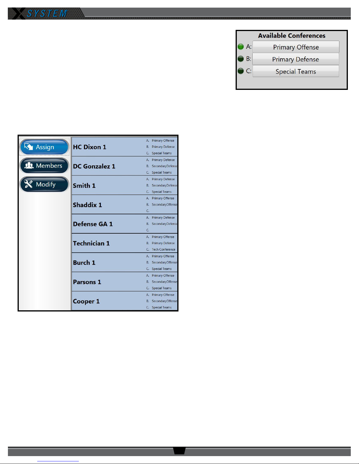
The list of available conferences on the RP Prole Screen displays the conferences
currently assigned to that RP’s prole. An illuminated green indicator shows the
RP’s current active conference.
You can quickly edit these assigned conferences by tapping/clicking on any
conference and selecting the new assignment from the conference list that
displays.
Note: If you change a conference on a prole, all Radio Packs with that prole
will change also.
Assigning New Proles
The Assign button enables you to quickly assign a new
prole to the selected RP. The right-hand list displays the
available proles for the type of RP selected (i.e., only
900MHz proles will display if you selected a 900MHz RP).
To change the prole, tap/click the desired prole from the
list. Conrm your selection on the prompt that displays.
You can choose whether to load user settings from the new
prole or retain the selected RP’s current user settings.
(User settings include the items listed under the “Modify”
view. See page 37 for more information.)
Figure 46: RP Prole Screen’s Available Conferences List
Figure 47: X-Ware Assign Prole View
800.749.2761 www.coachcomm.com
36
Page 41
Members View
OPERATING MANUAL
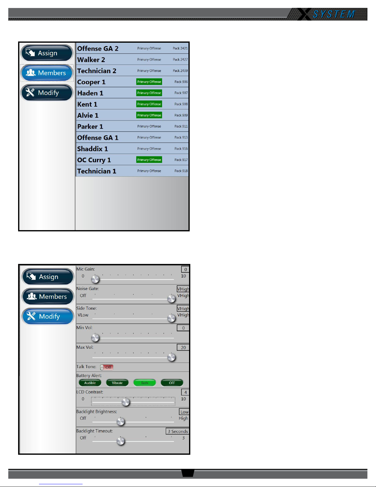
The Members button enables you to view a list of all users
the selected RP has access to. Users not on the selected
RP’s active conference will appear at the bottom of the
list, but they will be grayed out.
Clicking one of the users on the list will take you to that
user’s RP Prole view.
Figure 48: X-Ware Members View
Modify Settings
The Modify button displays a list of User Settings that
can be customized for the selected RP. You can choose
to retain the prole’s default settings or customize the
settings once the prole is applied.
Figure 49: X-Ware Modify Settings View
800.749.2761 www.coachcomm.com
37
Page 42
OPERATING MANUAL
Additional System Views
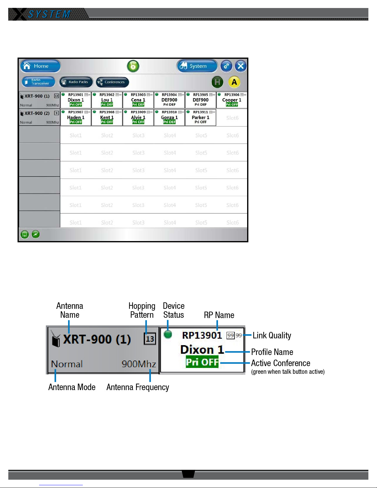
Radio Transceivers/Antennas View
The Radio Transceivers/Antennas
view provides information for each
Antenna currently connected to your
X-System.
This view also allows you to adjust
your system’s “Home” or “Away”
setting. (For more information about
this setting see page 28.)
Figure 50: X-Ware Radio Transceivers View
Each Antenna icon displays the Antenna’s name, hopping pattern, mode, and frequency. Each paired RP displays to the right
of its Antenna icon, and their icons display the device status (green for normal, red for error), RP name, link quality, prole
name, and active conference. (The conference displays green when the talk button is active.)
Figure 51: Radio Transceiver View Detail
800.749.2761 www.coachcomm.com
38
Page 43
Radio Packs View
OPERATING MANUAL
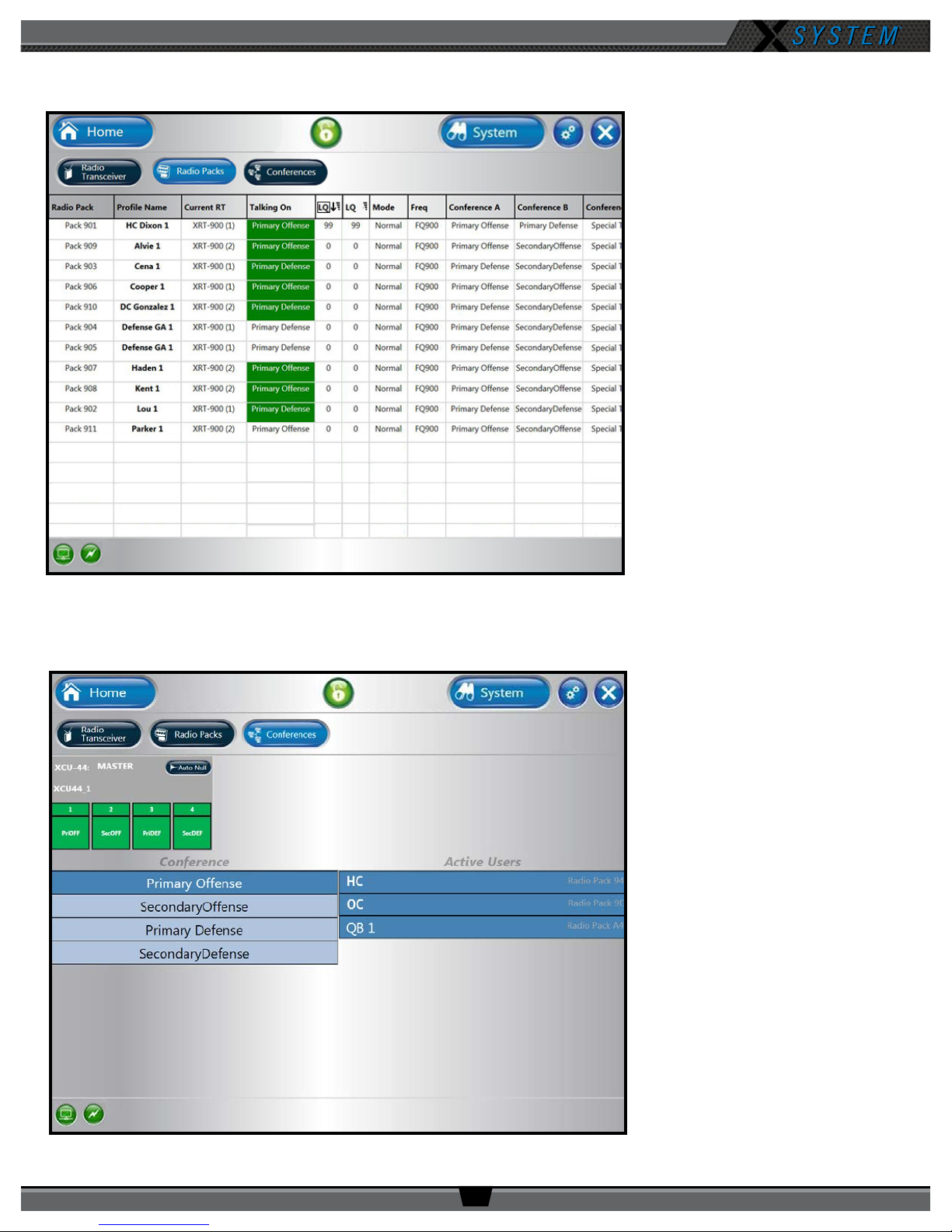
The Radio Packs view provides a list
of active RPs, along with the following
information about each one: Prole
Name, Current Antenna, Current
Conference, LQ, Mode, Frequency,
and Assigned Conferences.
This list can be sorted by clicking on
any column header.
You can also click on any RP in the list
to access that RP’s Prole View.
Figure 52: X-Ware Radio Packs View
Conferences View
The Conferences view displays a list
of the system’s conferences.
Clicking a conference from the list
will display the active users on that
conference in real time.
The X2 conguration has a
xed workow for conference
assignments; therefore, no changes
to the system are necessary. For
additional support on this view, we
recommend contacting CoachComm
Customer Support.
Figure 53: X-Ware Conferences View
800.749.2761 www.coachcomm.com
39
Page 44

OPERATING MANUAL
X-Ware Advanced Settings
X-Ware’s Advanced Settings interface is where the core operational settings for the system conguration reside. Changes
to these settings can impact system performance if made improperly. In particular, changes to these settings during “live”
operation on game day should be avoided. It is highly recommended you contact CoachComm Customer Support prior to
game day if changes are desired.
800.749.2761 www.coachcomm.com
40
Page 45
OPERATING MANUAL
System Conguration File
X-System’s Conguration File (CCF) contains everything about a system, including X-Net device locations, port assignments,
conferences, and proles. This le is used by the Control Unit, and it coordinates all device activity on the system. Only one
conguration le can be live on a system at any given time; however, you can save multiple versions of conguration les
locally or on a USB drive.
Each X-System is pre-congured by CoachComm with the customer’s desired settings. Saving, setup, and modications of
the conguration le are performed in X-Ware, if used. CoachComm’s Customer Support staff is available to help with any
advanced conguration needs during the season.
Saving a Conguration File
Changes to the conguration during operation will be saved at the Control Unit (CU). However, if you wish to save a copy of
the conguration le for later use, follow these procedures:
1. Insert a USB drive into your personal computer or laptop.
Note: Make sure the USB drive has enough space on it to save the le. 50 KB should be sufcient.
2. Connect your computer to the CU. See “Connecting X-Ware to Your CU” on page 32 for more details on this
process, if needed.
3. Make sure your CU is powered on. If you have not already done so, set the Home/Away status.
4. Launch X-Ware, then click the gear icon located at the top right of the home screen. This will launch X-Ware’s
Advanced Settings window. (See page 34 of this manual for more information about using X-Ware.)
5. Click the
to save a copy to the Documents folder on your personal computer or laptop.
Note: The le name must be 8 characters or less! It may be helpful to use school and date in the name.
6. Once the le has been saved to your USB drive, you can exit out of the software and eject the USB drive from the
computer.
Save File
For example, ASU1104, BAY1031, etc.
button on the top left of the screen and save your le to your USB drive. You may also choose
Loading a Conguration File
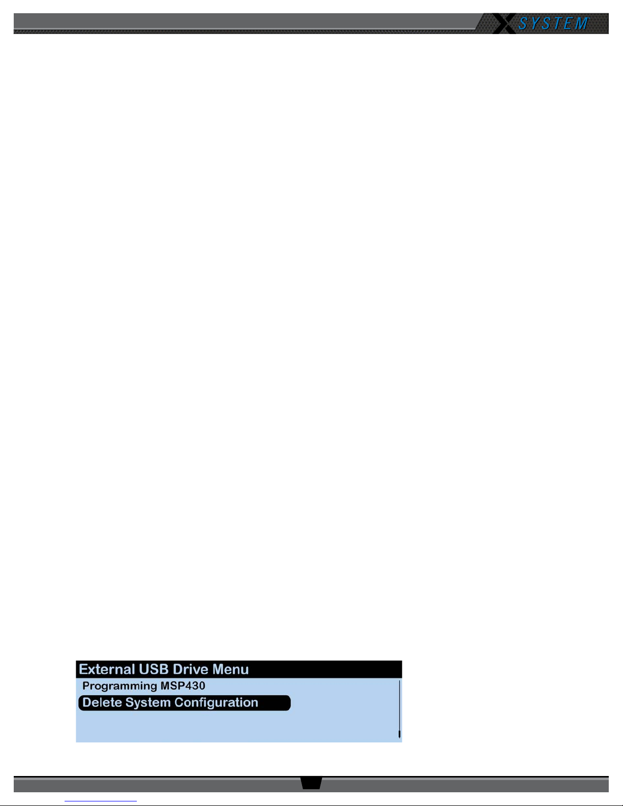
Follow these procedures when uploading a new conguration le to your system:
Important! Be sure you have saved a backup copy of your current conguration le prior to loading a
new one, in case you need to revert back to it for any reason.
1. Make sure your Control Unit (CU) is powered on and the current conguration le has completely loaded, then plug
the USB drive into the front of the CU. An External USB Drive menu screen will display on the CU LCD.
2. Navigate down the list of menu options until
and delete the current le that is stored on the CU.
Figure 54: CU LCD Delete Conguration File Prompt
800.749.2761 www.coachcomm.com
Delete System Conguration
41
is highlighted. Press the Enter button
Page 46
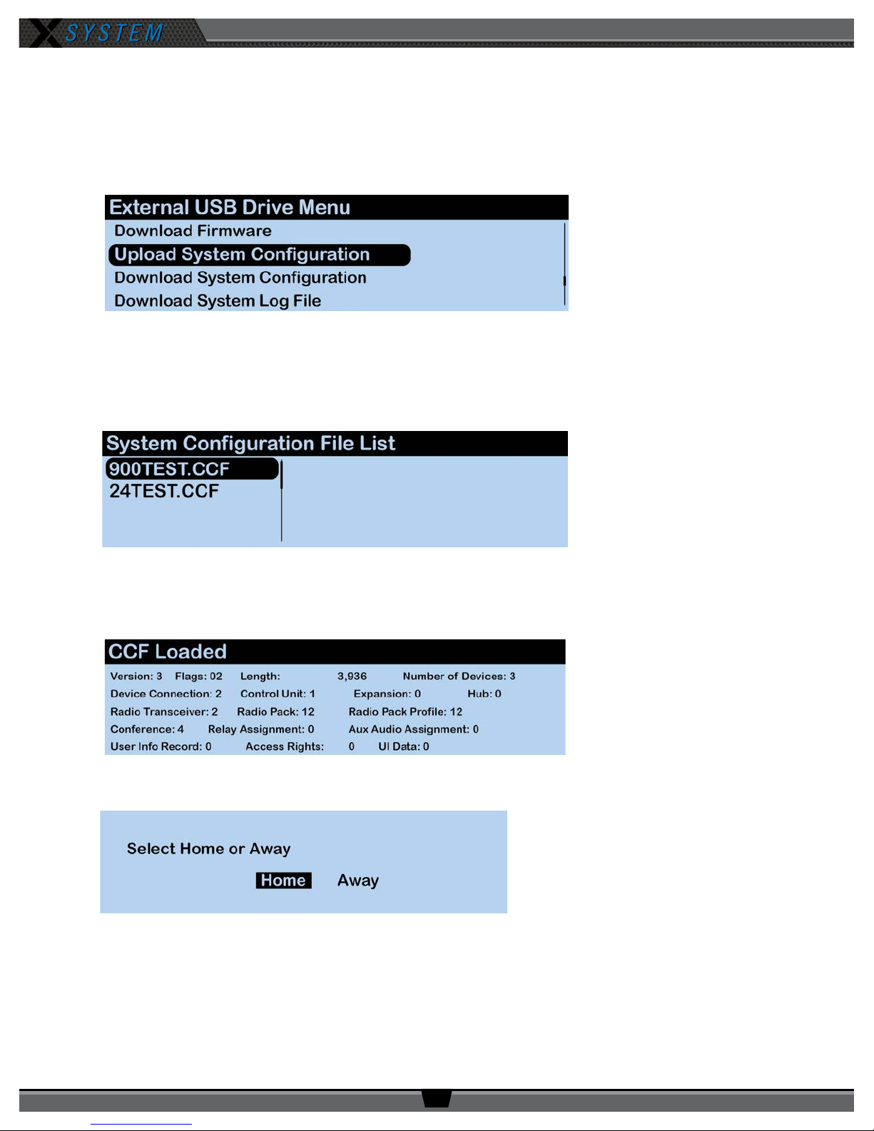
OPERATING MANUAL
3. Once the CU is nished deleting the old conguration le, wait an additional 60 seconds then remove the USB
drive and power cycle the CU.
4. After power cycling, select either
Home
or
Away
at the prompt on the CU screen. At startup, a blank grid will
display since the CU does not have a conguration le.
5. Re-insert your USB drive into the CU and navigate to the
Figure 55: CU LCD Upload Conguration File Prompt
Upload System Conguration
menu option.
6. Press the Enter button and scroll until you nd the conguration le you wish to use, then press the Enter button
to select it. The CU screen will display a blank grid while the conguration le loads.
7. Once the conguration le has nished loading, the CU will display the following message: “CCF Loaded” along
Figure 56: CU LCD List of Available Conguration Files
with a conguration le summary. Once the message times out, the home screen will display on the front of the
CU. Power off the CU.
Figure 57: CU LCD Conguration File Summary Screen
8. Power on the CU, then select
Figure 58: Control Unit Home/Away Status Prompt
Home
or
Away
. The new conguration le will load and be in use.
800.749.2761 www.coachcomm.com
42
Page 47

OPERATING MANUAL
System Maintenance
Basic Maintenance
CoachComm recommends the following best practices when maintaining your X-System components.
1. If the system is exposed to rain, dry all parts of X-System carefully, including cables and connectors.
2. Always make sure that nuts and bolts are secure prior to and after operating.
3. Connect or disconnect cables by holding the connectors (not the sheath of the cable) and pressing the release
button if applicable.
4. It is recommended that X-System be stored in a climate-controlled environment when not in use.
5. Storage Temperature: If a climate-controlled storage space is not available, X-System equipment can be stored
in temperatures ranging from 5° to 130° F. However, when going from cold to warm environments, electronics can
form condensation, which can cause damage to the electronic components. If storing your system in these types
of conditions, wait for the equipment to acclimate to the ambient temperature before using.
Lithium-Polymer Battery Maintenance
Storage of your Lithium-Polymer Batteries
When stored, a battery gradually loses its overall charge time due to internal self-discharge, which may reduce its overall
power. If storing batteries for two or more weeks, CoachComm highly recommends storing them at a 40–50% charge level,
which generally minimizes any permanent power capacity loss.
Unused lithium-polymer batteries may enter into a deep discharge state due to internal self-discharge. Once a battery has
gone into deep discharge, its onboard circuit protections inhibit the charger from initiating the charge cycle. If a battery
does not accept a charge and the LED displays red in the charger, the battery may be in deep discharge. An attempt
to revive the battery can be made by repeatedly inserting and removing it several times from the 5-Bay charger (CBT5BAY-01).
Ambient temperature affects the rate at which lithium-polymer batteries degrade. Batteries also degrade and lose overall
power capacity if stored (or used) at higher temperatures.
Proper Disposal of Old Lithium-Polymer Batteries
Batteries that appear swollen, deformed, or damaged, or that do not t properly should never be used. Properly dispose of
any batteries in this condition in accordance with the instructions provided by your local authorities. For more information
and local drop-off sites, visit http://www.call2recycle.org/.
Battery Shipping Regulations
Rechargeable lithium-polymer batteries are subject to special U.S. and International regulations, particularly regarding
transportation. The guidelines detailed in CoachComm’s Lithium-Polymer Battery Shipping Guidelines document comply
with updated International Air Transport Association (IATA), International Civil Aviation Organization (ICAO), and U.S.
Department of Transportation (DOT) Dangerous and Hazardous Goods regulations.
Spare lithium batteries are not allowed in checked airline baggage. Be sure to follow all FAA, IATA, and airline rules and
regulations when traveling with your X-System.
When shipping equipment to CoachComm that includes batteries, it is the shipper’s responsibility to ensure that batteries
are properly packaged, labeled, and shipped according to local and international guidelines. “Shipper” is dened as the
person or school placing the equipment in the package and offering it to the carrier.
800.749.2761 www.coachcomm.com
43
Page 48
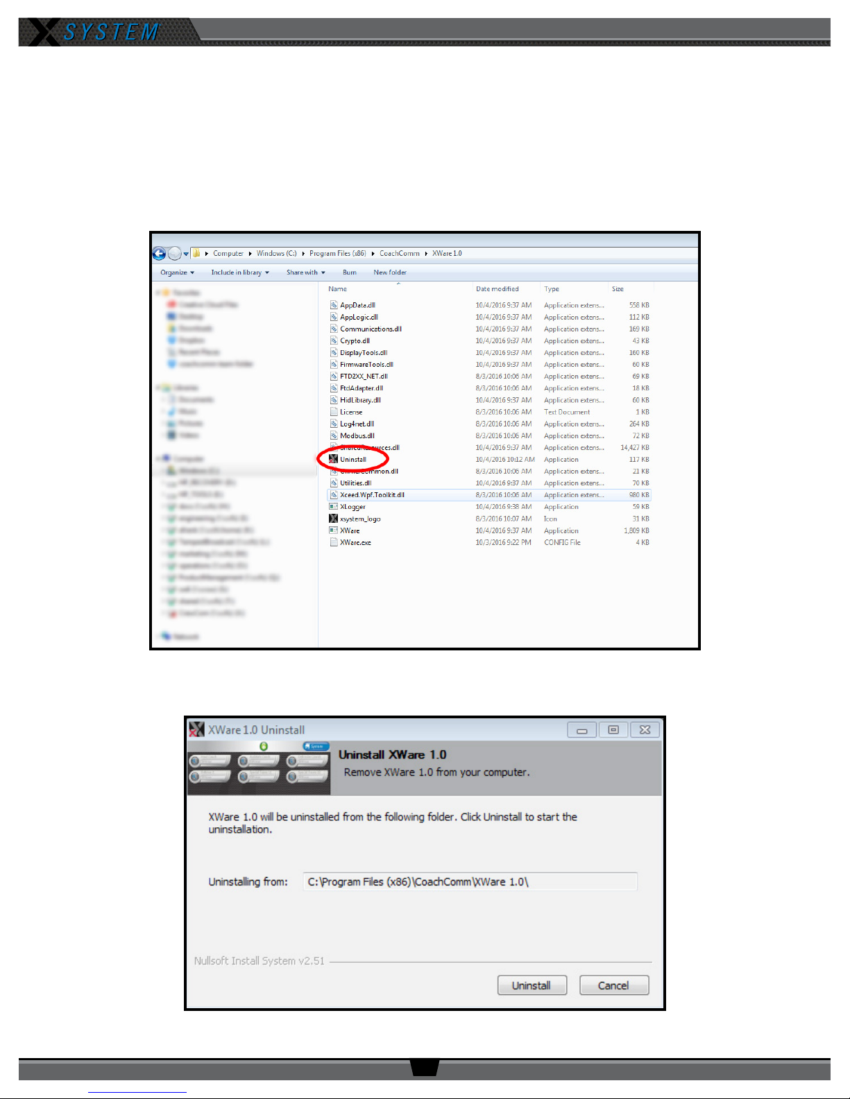
OPERATING MANUAL
Updating X-Ware
When a new version of X-Ware is released and made available for your system, follow the instructions below to update the
version of X-Ware installed on your PC.
Note: Be sure to save a copy of your current conguration le before updating X-Ware.
1. Locate X-Ware application les on PC at C:\Program Files (x86)\CoachComm\XWare.
2. Double-click the “Uninstall” application le within this folder. An uninstall dialog box will display.
3. Click
Figure 59: X-Ware Uninstall Application File
Uninstall
to begin process.
Figure 60: Uninstall Process Screen
800.749.2761 www.coachcomm.com
44
Page 49
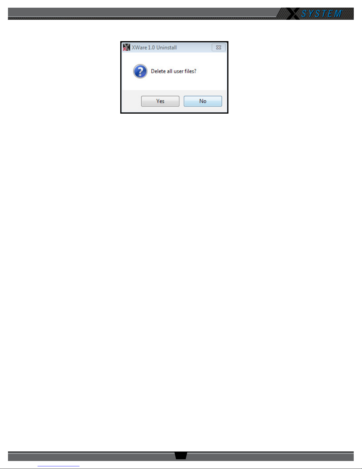
OPERATING MANUAL
4. You will be asked to conrm your decision to “Delete all user les.” Click
Figure 61: Conrm X-Ware Uninstall Screen
Close
5. The uninstall process will complete. Click
. Verify the original X-Ware folder is now empty. If not, delete any
Yes
.
remaining les.
6. Reboot/restart the PC. Once the PC powers back on follow the procedures found on page 30 to install the new
version of X-Ware.
IMPORTANT: The rmware on your X-System devices will also need to be updated to match the version of
X-Ware installed on your PC. To update device rmware, see the following section.
Updating Device Firmware
The current rmware package requires connecting devices directly to the PC USB for rmware updates. Update times may
vary depending on equipment’s rmware package. Each updated package will speed up the rmware process per device.
Prerequisites:
IMPORTANT: Always follow any specic rmware update instructions delivered with the new release. Firmware
release notes and any separately published update procedures supercede the information provided below.
• Make sure that the most recent version of X-Ware is installed on the PC. See page 44 for more information
about how to update X-Ware.
• Connect the Antennas to the system so they will receive power, then power on the Control Unit (CU) and allow it to
load the Conguration File.
Firmware Update:
1. Open X-Ware and wait for the home screen to load.
2. On the top right of the home screen, click the Advanced Settings button (gears icon).
800.749.2761 www.coachcomm.com
45
Page 50
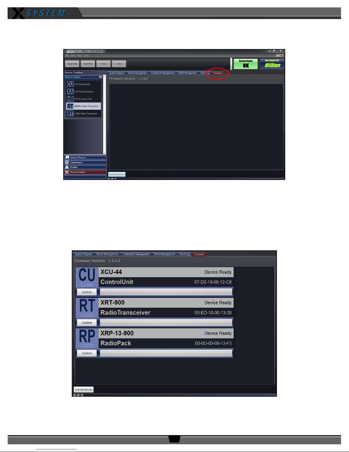
OPERATING MANUAL
3. Navigate to the “Firmware” tab of the advanced settings.
4. Connect a USB to Micro USB cable from the PC to the device (micro end goes into X-System device).
Figure 62: X-Ware Firmware Tab
NOTE: You can utilize a USB “hub” in order to do multiple devices at once; be sure all devices are connected
prior to Step 5.
5. Click the
Scan For Devices
button at bottom of the tab.
6. Each connected device will display in a list on the tab. This list will include each device’s current rmware
version.
Figure 63: Connected Devices
800.749.2761 www.coachcomm.com
46
Page 51
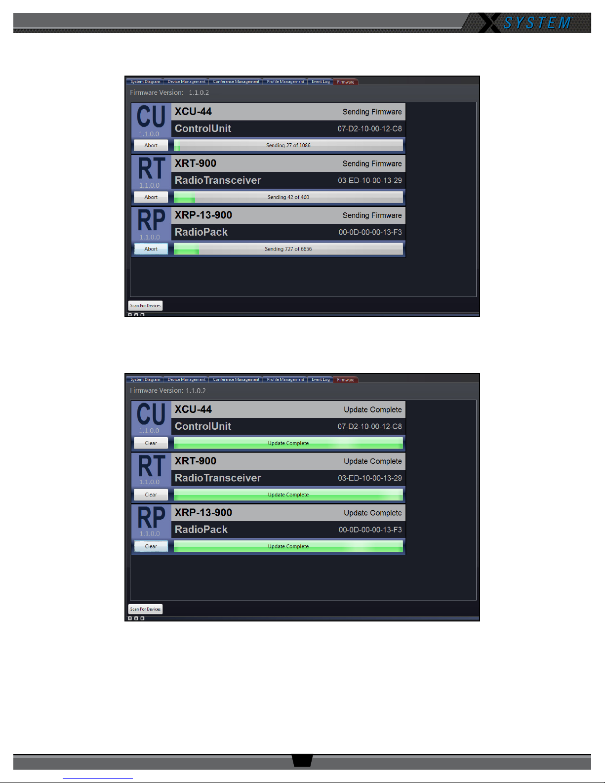
OPERATING MANUAL
7. Click the
device.
Update
button on each device to upload the latest rmware on it. A progress bar will display for each
Figure 64: Device Firmware In Progress
8. Once the upload is complete, the device progress bar will read “Update Complete.” Click the
remove that device from the list.
Figure 65: Completed Firmware Update
Clear
button to
9. Verify the rmware installation by repeating steps 4–6 to rescan the devices. All scanned devices should now
display the current rmware version number.
10. Repeat steps 4–9 above for each Control Unit (CU), Antenna (Radio Transceiver), and Radio Pack (RP).
800.749.2761 www.coachcomm.com
47
Page 52
OPERATING MANUAL
Troubleshooting Common Issues
Symptom/s Potential Problem/s Corrective Action/s
Noise/Static/Hum on System or on
a Channel
Crosstalk Bad wired accessory such as a
Red LEDs on 5-Bay Charger Ambient temperature too high to
Faulty ground plug Move to another outlet, or apply ground
isolation adapter to plug.
Bad wired accessory such as Wired
BeltPack, cable, or headset
Wired BeltPack, cable, or headset
charge (safety mechanism)
Process of elimination: remove items on
line in question one at a time until problem
disappears.
Process of elimination: remove items on
combined lines one at a time until crosstalk
disappears.
Charge indoors or move chargers to a cooler
location.
800.749.2761 www.coachcomm.com
48
Page 53

OPERATING MANUAL
Product Support
CoachComm support and service personnel are ready to help you with any issues you may have. CoachComm offers
product support from 8:00 a.m. to 5:00 p.m. (CST), Monday through Friday. Customers who annually renew their support
plan have access to CoachComm’s 24/7 after-hours support hotline as well. (Access this line by dialing our voice number
and following the automated prompts to the After-Hours line. Leave a message there, and your call will be returned as soon
as possible.) Our company website, www.coachcomm.com, offers supporting product documentation and live chat for help.
All questions and/or requests for a Return Material Authorization (RMA) Number should be directed to the Customer Service
department:
CoachComm Customer Service Department
Voice: 1.800.749.2761
Fax: 1.888.329.2658
Email: [email protected]
Returning Equipment for Repair or Maintenance
Do not return any equipment directly to the factory without rst obtaining a Return Material Authorization (RMA) Number.
Obtaining a Return Material Authorization Number will ensure that your equipment is handled promptly.
All shipments of CoachComm products should be made via UPS, or the best available shipper, prepaid and insured. The
equipment should be shipped in the original packing carton; if that is not available, use any suitable container that is rigid
and of adequate size to surround the equipment with at least four inches of shock-absorbing material.
Battery Shipping Disclaimer: When shipping equipment to CoachComm that includes batteries, it is the shipper’s
responsibility to ensure that batteries are properly packaged, labeled, and shipped according to local and international
guidelines. “Shipper” is dened as the person or school placing the equipment in the package and offering it to the carrier.
Refer to CoachComm’s Lithium-Polymer Battery Shipping Guidelines document on our website for more information.
All shipments should be sent to the following address and must include a Return Material Authorization Number:
CoachComm Customer Service Department
Attn: Return Material Authorization #
205 Technology Parkway
Auburn, AL 36830-0500
800.749.2761 www.coachcomm.com
49
Page 54

OPERATING MANUAL
License Information
Radio Device License Information
Warning: Changes or modications to this device not expressly approved by CoachComm could void the user’s authority to operate
the equipment.
1. FCC Notices
1.1. This device complies with Part 15 of the FCC Rules. Operation is subject to the following two conditions: (1)
This device may not cause harmful interference, and (2) this device must accept any interference that may
cause undesired operation.
1.2. This equipment has been tested and found to comply with the limits for a Class A digital device, pursuant
to part 15 of the FCC rules. These limits are designed to provide reasonable protection against harmful
interference when the equipment is operated in a commercial environment. This equipment generates,
uses, and can radiate radio frequency energy and, if not installed and used in accordance with the
instruction manual, may cause harmful interference to radio communications. Operation of this equipment
in a residential area is likely to cause harmful interference in which case the user will be required to correct
the interference at his own expense.
2. Canada, Industry Canada (IC) Notices
2.1. This Class A digital apparatus complies with Canadian ICES-003.
Cet appareil numerique de la classe A est conforme a la norme NMB-003 du Canada.
2.2. Under Industry Canada regulations, this radio transmitter may only operate using an antenna of a type
and maximum (or lesser) gain approved for the transmitter by Industry Canada. To reduce potential
radio interference to other users, the antenna type and its gain should be so chosen that the equivalent
isotropically radiated power (e.i.r.p.) is not more than that necessary for successful communication.
Conformément à la réglementation d’Industrie Canada, le présent émetteur radio peut fonctionner avec une
antenne d’un type et d’un gain maximal (ou inférieur) approuvé pour l’émetteur par Industrie Canada. Dans
le but de réduire les risques de brouillage radioélectrique à l’intention des autres utilisateurs, il faut choisir
le type d’antenne et son gain de sorte que la puissance isotrope rayonnée équivalente (p.i.r.e.) ne dépasse
pas l’intensité nécessaire à l’établissement d’une communication satisfaisante.
2.3. This radio transmitter (FCCID: HSW-CCT24 & HSW-CCT900, IC: 4492A-CCT24 & 4492A-CCT900) has been
approved by Industry Canada to operate with the antenna types listed below with the maximum permissible
gain and required antenna impedance for each antenna type indicated. Antenna types not included in this
list, having a gain greater than the maximum gain indicated for that type, are strictly prohibited for use with
this device.
Le présent émetteur radio (FCCID: HSW-CCT24 & HSW-CCT900, IC: 4492A-CCT24 & 4492A-CCT900) a été
approuvé par Industrie Canada pour fonctionner avec les types d’antenne énumérés ci-dessous et ayant
un gain admissible maximal et l’impédance requise pour chaque type d’antenne. Les types d’antenne non
inclus dans cette liste, ou dont le gain est supérieur au gain maximal indiqué, sont strictement interdits pour
l’exploitation de l’émetteur.
800.749.2761 www.coachcomm.com
50
Page 55

OPERATING MANUAL
2.4. This device complies with Industry Canada licence-exempt RSS standard(s). Operation is subject to the
following two conditions: (1) this device may not cause interference, and (2) this device must accept any
interference, including interference that may cause undesired operation of the device.
Le présent appareil est conforme aux CNR d’Industrie Canada applicables aux appareils radio exempts
de licence. L’exploitation est autorisée aux deux conditions suivantes : (1) l’appareil ne doit pas produire
de brouillage, et (2) l’utilisateur de l’appareil doit accepter tout brouillage radioélectrique subi, même si le
brouillage est susceptible d’en compromettre le fonctionnement.
RF-Exposure Statements
Radio Packs
X-System Radio Packs have been designed to be worn and used in close proximity to the human body—what the FCC calls
a “portable” use.
This equipment complies with FCC radiation exposure limits set forth for an uncontrolled environment. This equipment is
in direct contact with the body of the user under normal operating conditions. This transmitter must not be co-located or
operating in conjunction with any other antenna or transmitter.
Radio Transceiver/Antenna
The X-System Radio Transceiver/Antenna has been designed for use as what the FCC calls a “mobile” device.
This equipment complies with FCC radiation exposure limits set forth for an uncontrolled environment. This equipment
should be installed and operated with minimum distance 20 cm (7.87 in.) between the radiator and your body. This
transmitter must not be co-located or operating in conjunction with any other antenna or transmitter.
Non-Radio-Device License Information
Warning: Changes or modications to this device not expressly approved by CoachComm could void the user’s
authority to operate the equipment.
1. FCC Notices
1.1. This device complies with Part 15 of the FCC Rules. Operation is subject to the following two conditions: (1)
This device may not cause harmful interference, and (2) this device must accept any interference that may
cause undesired operation.
1.2. This equipment has been tested and found to comply with the limits for a Class A digital device, pursuant
to part 15 of the FCC rules. These limits are designed to provide reasonable protection against harmful
interference when the equipment is operated in a commercial environment. This equipment generates,
uses, and can radiate radio frequency energy and, if not installed and used in accordance with the
instruction manual, may cause harmful interference to radio communications. Operation of this equipment
in a residential area is likely to cause harmful interference in which case the user will be required to correct
the interference at his own expense.
1. Canada, Industry Canada (IC) Notices
1.1. This Class A digital apparatus meets all requirements of the Canadian Interference Causing Equipment
Regulations.
Cet appareillage numérique de la classe A répond à toutes les exigencies de l’interférence canadienne
causant des règlements d’équipment.
800.749.2761 www.coachcomm.com
51
Page 56

OPERATING MANUAL
Warranty Information
Limited Warranty
CoachComm, LLC products are warranted to be free from defects in materials and workmanship for a period of one year
from the date of sale to the end user.
Exceptions to this warranty coverage are Tempest® and Connex® systems, which will continue to have a two-year product
warranty.
The purchase of a maintenance and support plan is not a condition of coverage under this limited warranty; however,
purchasing a plan does extend a product’s warranty for an additional year.
The sole obligation of CoachComm, LLC during the warranty period is to provide, without charge, parts and labor necessary
to remedy covered defects appearing in products returned prepaid to CoachComm, LLC. This warranty does not cover any
defect, malfunction, or failure caused by circumstances beyond the control of CoachComm, LLC, including but not limited to
negligent operation, abuse, accident, failure to follow instructions in the Operating Manual, defective or improper associated
equipment, attempts at modication and/or repair not authorized by CoachComm, LLC, and shipping damage. Products with
their serial numbers removed or effaced are not covered by this warranty.
This limited warranty is the sole and exclusive express warranty given with respect to CoachComm, LLC products. It is
the responsibility of the user to determine before purchase that this product is suitable for the user’s intended purpose.
ANY AND ALL IMPLIED WARRANTIES, INCLUDING THE IMPLIED WARRANTY OF MERCHANTABILITY, ARE LIMITED TO THE
DURATION OF THIS EXPRESS LIMITED WARRANTY. NEITHER COACHCOMM, LLC NOR ANY AUTHORIZED RESELLER WHO
SELLS COACHCOMM PRODUCTS IS LIABLE FOR INCIDENTAL OR CONSEQUENTIAL DAMAGES OF ANY KIND.
Parts Limited Warranty
Replacement parts for CoachComm, LLC products are warranted to be free from defects in materials and workmanship for
120 days from the date of sale to the end user.
This warranty does not cover any defect, malfunction, or failure caused by circumstances beyond the control of
CoachComm, LLC, including but not limited to negligent operation, abuse, accident, failure to follow instructions in the
Operating Manual, defective or improper associated equipment, attempts at modication and/or repair not authorized by
CoachComm, LLC, and shipping damage. Any damage done to a replacement part during its installation voids the warranty
of the replacement part.
This limited warranty is the sole and exclusive express warranty given with respect to CoachComm, LLC products. It is
the responsibility of the user to determine before purchase that this product is suitable for the user’s intended purpose.
ANY AND ALL IMPLIED WARRANTIES, INCLUDING THE IMPLIED WARRANTY OF MERCHANTABILITY, ARE LIMITED TO THE
DURATION OF THIS EXPRESS LIMITED WARRANTY. NEITHER COACHCOMM, LLC NOR ANY AUTHORIZED RESELLER WHO
SELLS COACHCOMM PRODUCTS IS LIABLE FOR INCIDENTAL OR CONSEQUENTIAL DAMAGES OF ANY KIND.
Battery Warranty
CoachComm provides a 6-month warranty for all CoachComm branded lithium-polymer rechargeable batteries (six months
from the date of sale to and purchase by the end user). The warranty period is based upon the expectation that the battery
will deliver 80% of its initial capacity after 300 cycles at typical power loads. Lithium-polymer batteries will continue
to operate below 80% capacity threshold; however, the capacity (run time) delivered between charges will continue to
decrease. Apart from this warranty, batteries are also covered as part of the X-System annual maintenance plan.
800.749.2761 www.coachcomm.com
52
Page 57

OPERATING MANUAL
Glossary
Conference - A grouping of audio entities. Radio Packs may subscribe to one or more conferences.
Mic Gain - Increase in the power of the signal from the microphone
Mic Type - Either electret or dynamic, determined by user selection or system auto-detection
Noise Gate - Dynamic processor that suppresses unwanted noise present when the audio signal is at a low level
Prole - A Radio Pack prole assigns functionality to a Radio Pack’s local controls, knobs, and buttons as well as what
conferences they subscribe to.
Sidetone - The user’s own voice folded back into the user’s ear. This adjustment allows for a user to hear more or less of
his/her own voice in his/her headset. If sidetone is turned down, the user can still hear other users but he/she cannot hear
his/her own voice. If the sidetone is turned up too far, the user may cause “feedback” or squealing on his/her intercom line.
Radio Transceiver - (also known as “Antenna”) A device used to remotely locate a radio and its Antenna to provide better
and more expanded coverage area for wireless communication.
800.749.2761 www.coachcomm.com
53
Page 58
OPERATING MANUAL
Specications
*Notice About Specications: While CoachComm makes every attempt to maintain the accuracy of the information
contained in this manual, this information is subject to change without notice. Please check our website for the latest
system specications and certications.
Control Unit Specications
Table 2: Control Unit Specications
Control Unit Specication XCU-44
Hardwired Intercom Audio Channels (per CU) 8 (four 2-wire and four 4-wire)
Active Radio Packs (Normal Mode) (per CU) 12
USB Ports (1) USB Type A; (1) Micro USB
Front Panel LCD Display 512 × 128 resolution
Stage Announce and GPO Closures 5 Relays via DA-15
X-Net Ports (supports 2 connections) (2) RJ-45 for copper; (1) duplex LC for Single Mode Fiber
Sync In Ports (supports 1 connection) (1) RJ-45 for copper; (1) duplex LC for Single Mode Fiber
2-Wire Intercom Connection
2-Wire Compatibility Clear-Com, RTS, and AudioCom (Balanced)
4-Wire Intercom Connection 4 ports via RJ-45
Stage Announce Output XLR 3M, nominal 12 dBu into 600 ohms, balanced, transformer isolated
AUX IN
AUX OUT
LAN Port (1) RJ-45
Power Input/Connector 100–240V ~ 50–60 Hz, 1.8A
Dimensions
Weight 6.5 lbs (2.9 kg)
Operating Environment -20° to 50° C (-4° to 122° F); 10% to 90% Humidity.
Maximum Line Length Copper 330 ft. (100 m); Fiber 32,800 ft. (10,000 m)
Maximum Altitude 9,842 ft. (3,000 m)
RoHS Compliant Yes
4 channels via XLR 3F
with XLR 3M loop (4 ports)
1/4” (6.35 mm) 3 conductor jack, 17.5 dBu max in,
balanced, transformer isolated
1/4” (6.35 mm) 3 conductor jack, 12 dBu into 600 ohms,
balanced, transformer isolated
1 RU, 19 in. × 1.73in. × 11.68 in. (48.3 cm × 4.4 cm × 29.7 cm) metal
enclosure
800.749.2761 www.coachcomm.com
54
Page 59
OPERATING MANUAL
Radio Transceiver/Antenna Specications
Table 3: Radio Transceiver/Antenna Specications
Radio Transceiver/Antenna Specication XRT-ANT-900
RF Frequency (MHz) 902–928 MHz
RF Scheme FHSS with TDMA
Effective Radiated Power 400 mW (+26dBm)
Receiver Sensitivity -100 dBm at 10
-5
BER
Radio Certication
FCCID: HSW-CCT900 and
IC: 4492A-CCT900
650 ft. (200 m) under typical conditions; 1950 ft. (600 m) line of sight
Transmission Range
(Note: Functional range depends on many variables, including RF
signal absorption, reection, and external interference.)
No. of Radio Packs Supported (when Antenna in
Normal Mode)
No. of Radio Packs Supported (when Antenna in
High Density Mode)
6
32
Supplied Antenna +5dBi Directional (integrated patch)
X-NET IN Port (supports 1 connection) (1) RJ-45
RT LOOP Port (1) RJ-45
Maximum Line Length Copper 330 ft. (100 m)
Network Power X-Net RJ-45 only
Dimensions (inches) 6.30 in. × 7.74 in. × 1.81 in. (16 cm × 19.7 cm × 4.6 cm)
Weight 1.25 lbs (567 g)
Operating Environment -20° to 50° C (-4° to 122° F); 10% to 90% Humidity
Maximum Altitude 9,842 ft. (3,000 m)
RoHS Compliant Yes
800.749.2761 www.coachcomm.com
55
Page 60
OPERATING MANUAL
Radio Pack Specications
Table 4: Radio Pack Specications
Radio Pack Specication XRP-13-900
RF Frequency (MHz) 902–928 MHz
RF Scheme FHSS with TDMA
Effective Radiated Power 400 mW (+26 dBm)
Receiver Sensitivity -100 dBm at 10
-5
BER
Radio Certication
FFCCID: HSW-CCT900 and
IC: 4492A-CCT900
650 ft. (200 m) under typical conditions; 1950 ft. (600 m) line of sight
Transmission Range
(Note: Functional range depends on many variables, including RF signal
absorption, reection, and external interference.)
Audio Dynamic Range Greater than 90 dB
Audio Frequency Response 150 Hz–7 kHz
Conferences 3
Simultaneous Listen Paths 1
Volume Knobs 1
Talk Buttons 1
Headset Connector 4-pin male XLR
USB Port (1) Micro USB
Microphone Type Auto Detect or Manual Select; Dynamic or Electret
LCD Display 280 × 64 resolution
Antenna (internal) (2) 2dBi Dipole
Battery Life, Rechargeable Lithium-Polymer Greater than 9 hours
Charging Power Supply Micro USB; 6W AC wall adapter
Charge time for Lithium-Polymer Battery Under 3 hours
Optional Power 3 Standard AA batteries
Battery Life, Alkaline batteries Approximately 4.5 hours
Dimensions (inches) 4.5 in. × 4.57 in. × 2.31 in. (11.4 cm × 11.6 cm × 5.9 cm)
Weight (with Lithium-Polymer battery) 13 oz. (369 g)
Material Polycarbonate substrate with thermoplastic elastomer overmold
Operating Environment
-20° to 50° C (-4° to 122° F); 10% to 90% Humidity.
RP Power Adapter is 0 to 40° C (32° to 104° F).
Maximum Altitude 9,842 ft. (3,000 m)
RoHS Compliant Yes
800.749.2761 www.coachcomm.com
56
Page 61

OPERATING MANUAL
This page is intentionally blank.
800.749.2761 www.coachcomm.com
57
Page 62

OPERATING MANUAL
CoachComm LLC
205 Technology Parkway
Auburn, Alabama 36830
1.800.749.2761
www.coachcomm.com
Copyright © 2018 CoachComm LLC. All rights reserved. The Tempest®, Connex®, and
SmartBoom® word marks and Tempest® and X-System logos are trademarks of CoachComm
LLC. Any and all other trademark references within this document are property of their
respective owners.
Document Reference: 2018.03 D0000383_A
 Loading...