

Page 1
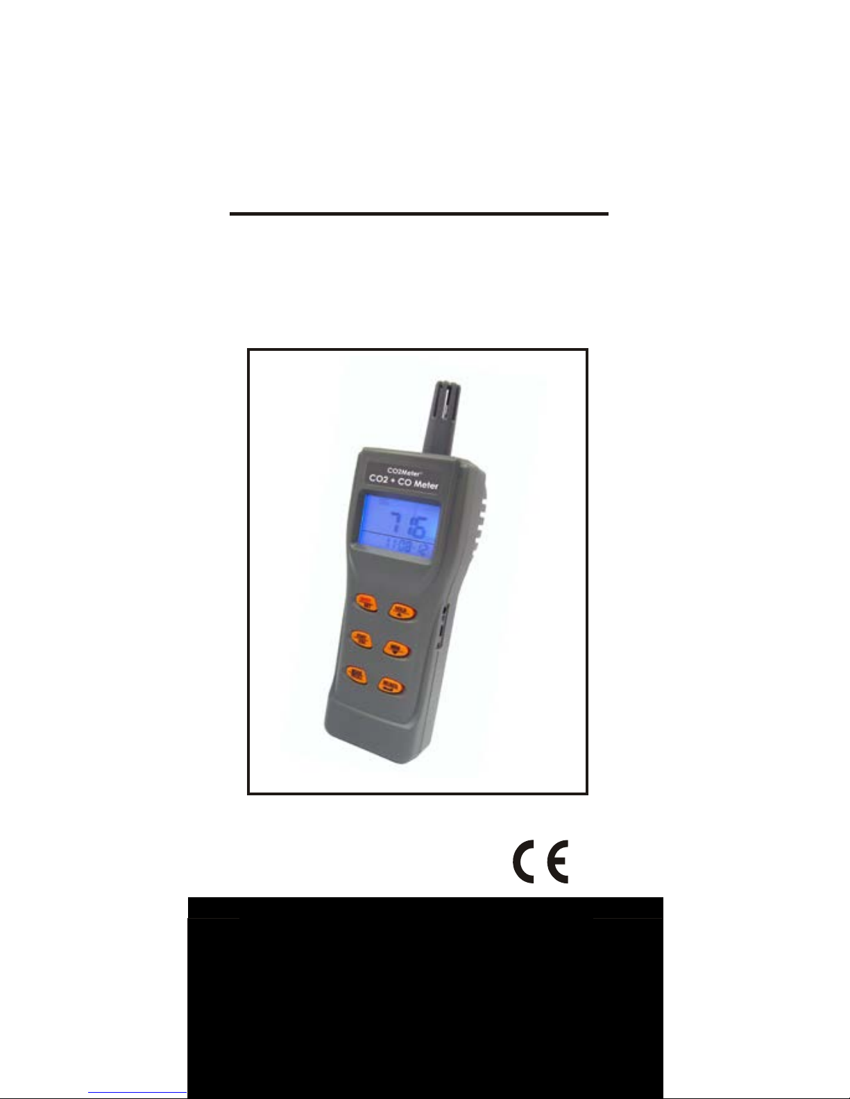
OPERATION MANUAL
PORTABLE IAQ METER
CO2Meter.com
131 Business Center Drive
Ormond Beach, FL 32174 USA
Support: (386) 256-4910
Email: [email protected]
Page 2

Thank you for
purchasing t
his portable
Indoor Air Quality (
I
AQ) me ter. The meter
me
asures
the carbon dioxide (
CO
2) level
,
carbon monoxide (
CO) level,
air
t
emperature, dew point,
wet bulb
t
emperature and humidity, and is an ideal
portable
instrument for IAQ diagnosis.
Poor indoor air quality is considered
unheal
thy
because it
causes t
iredness
,
los
s of
ability to
concentrate,
and even
illness
(for example: Sick Building
Syndro
me). IAQ
moni
t
oring
has
become
widel
y applied in public areas such as
o
ff
ices, classrooms, fact
ories,
hospitals
an
d hotels. It is
also suggested in
regula
t
ions of
industrial hygiene in some
coun
t
ries (see Appendix).
The portable CO2 meter uses NDIR (nondispersive
infrared) t
echnology to
ensure
reliabili
ty
and long t
erm stability. It is
use
ful in
verifying HVAC system
performance
and air ventilation control.
The IAQ meter also measures carbo n
monoxide. CO is a colorless,
odorless,
and tast
eless gas which is lighter t
han air
.
It is highly t
oxic to
humans and anima ls.
The maximum
CO
indoor air quality level
per ASHRAE Residential standards 621989
for
living area is under 9ppm.
Besides, it is also necessary to
remove
employees from enclosed space if the
CO concentration exceeds 100ppm per
the
OSHA exposure limit. Please refer t
o
the Appendix for the details.
1
INTRODUCTION
Page 3

This package contains:
Meter
4 AA batteries
Mini USB cable and software C
D
Operation manual
Hard carrying case
Adaptor (9V/100~240Vac)
33% calibrati on salt
75% cali bration salt
2
MATERIAL SUPPLIED
Features:
• Big LCD display with blue
backlight to use in dark area
• One touch to display CO
2 /Dew
Point temperature/Wet bulb
temperature/
• Air temperature/Humidity/CO in
turns. Designed with NDIR (nondispersive infrared) Waveguide
technology CO
2 sensor
• Programmable warning CO level
• Long term NDIR CO2 sensor drift
compensation
• Audible alarm (~80db) threshold
setting Max, Min, TWA, STEL
functions included Mini USB to PC
download function for analysis
• 99 memory points manually
recorded
• 24,000 data points auto recording
• Review 99 points manual record
• Hold function freezes current
readings Wide, slotted housing
design improves air ventilation for
quicker and more accurate
response
• Easy to manually calibrate
CO2 in fresh air (~400ppm).
Page 4
The meter is powered by either 4 AA
batteries or a DC adaptor (9V/1A output).
Install the batteries into the battery
compartment on the rear and make sur
e
they are in correct polarity and good
contact. When an adaptor is used, it wil
l
cut off the power supply from batteries.
The adaptor can’t be used as a battery
charger.
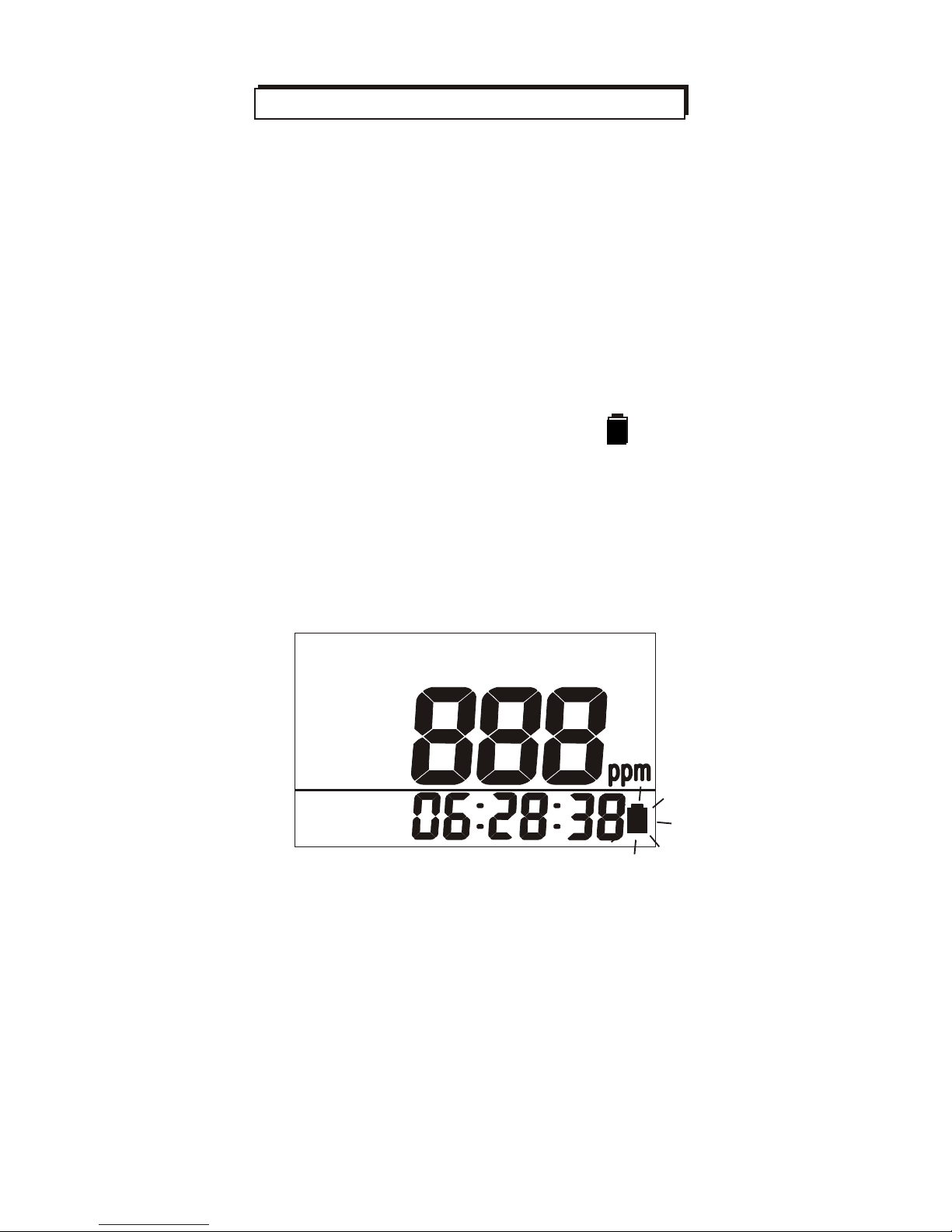
When battery voltage gets low
B
will
appear on the LCD (Fig.1).
The CO2 sensor cannot work normally
under low voltage. Please replace wit
h
fresh batteries or connect the adaptor.
Fig.1
3
CO
2
PM
B
POWER SUPPLY
Page 5
MIN
AVG
TWA
O O
F
AM
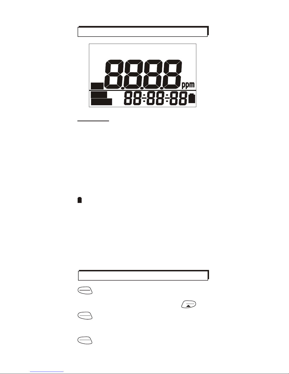
Symbols
UpperLCD CO2/CO/Temp/RH
display
LowerLCD Clock/timer display
CO
2
CO
HOLD
MIN/MA
X
STEL
Carbon dioxide reading
Carbon monoxide reading
Readings are frozen unchanged
Minimum/Maximum readings
Short-term exposure limit (15
minutes weighted average)
Time weighted average (8 hours)
Low battery indicator
Dew point temperature
Dry air temperature
Wet bulb temperature
Unit of relative humidity
Celsius/Fahrenheit temperature
In calibration mode
In manual/automatic logging
In manual records recall mode
TWA
B
DP
TA
WBT
%RH
o C/o
F
CAL
REC
RECALL
Turns on and off the meter.
Enters setup mode while meter is off
.
Sets as non-sleep mode with
HOLD
.
Exits setup/recall page.
Start automatic logging.
ON/OFF
SET
START
ESC
Press to switch displayed mode.
Long press to enter memory recall mode.
4
MODE
RECALL
KEYPAD
HOLD
CO
2
CO
TADPWBT
MAX
C
STEL
%rh
CAL
REC
B
Re call
LCD DISPLAY
Page 6
HOLD
Freezes the current readings.
Selects unit or increases value in setup.
Cancels data hold function.
MEM
Press to manually record the reading.
Selects unit or decreases value in setup.
POWER ON/OFF
Press to turn the meter on and off.
M
N/AVG
Activates MIN, MAX, TWA, TEL
X
function. Saves and finishes settings.
ON/OFF
SET
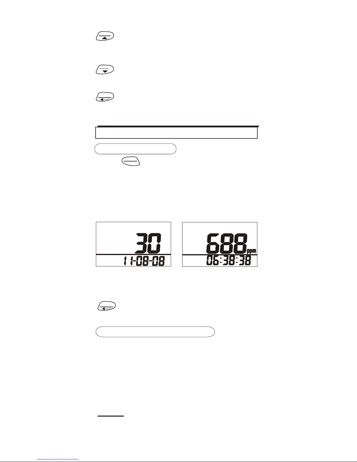
At power up, it emits a short beep and
performs a 30 second countdown
(Fig.2). It then displays the normal mode
and clock
(Fig.3). The real time display
will cycle between date and time in turns.
Fig.2
Fig.3
While waiting for 30 seconds to warm up
is best, for a quick start you can press
M X/AVG
N
for 2 seconds to end the warm up
and show the normal display.
TAKING MEASUREMENT
The meter starts when the power is
turned on and updates readings every
second. When the operating
environment changes quickly (ex.
going outdoors on a cold day), it can
takes 30 seconds
for the CO
2
level to
change and u p to 30 minutes for RH.
NOTE: Do not hold the meter close to
your
face. Exhalation affects the CO
2
levels.
5
CO
2
AM
OPERATION
Page 7
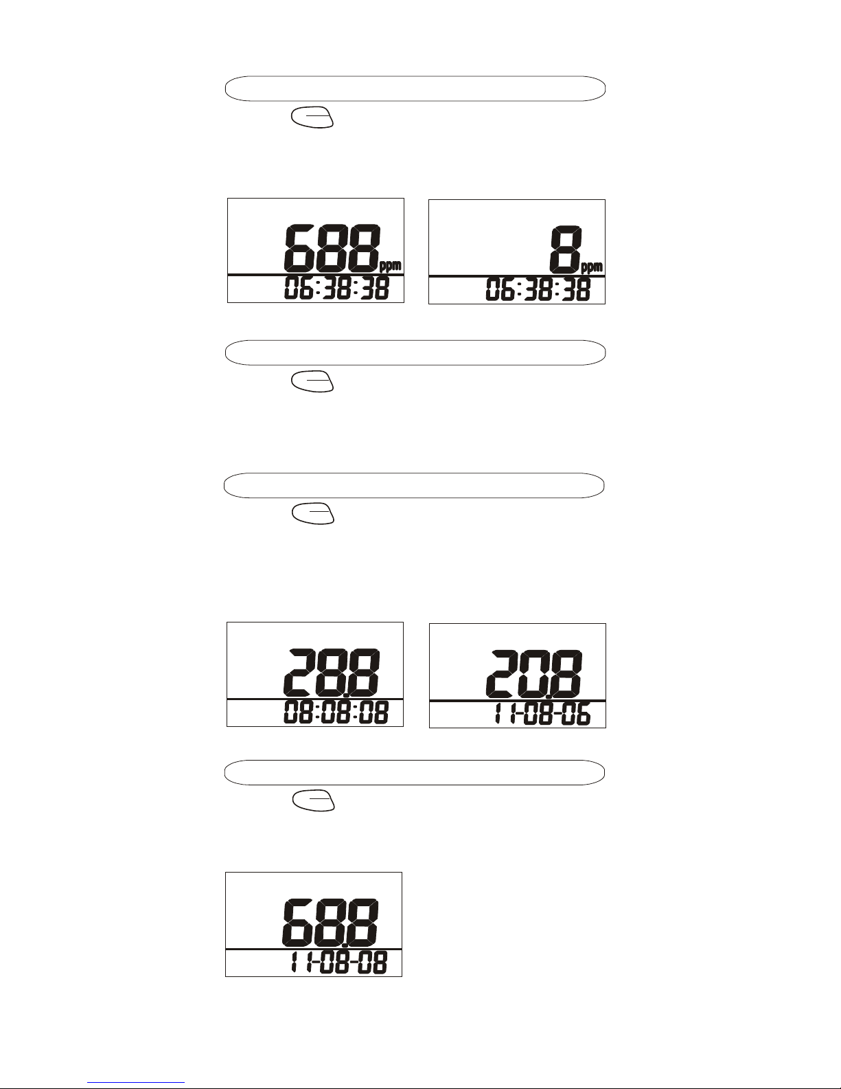
CO2 (Carbon Dioxide)
RECALL
to switch the mode to CO2.
You can view the CO2 reading in ppm o
n
the main display (Fig.4). The lower
display shows the real time clock.
Press
MODE
Fig.4
Fig.5
CO (Carbon Monoxide)
RECALL
to switch the mode to CO.
You can view the CO reading in ppm
on the main display (Fig.5). The lower
display shows the real time clock.
AIR, DP, WB Temperature
Press
MODE
to switch to temperature
display (Fig.6). You can view the dew
point temperature, and next the wet bul
b
temperature (Fig.7). The lower displa
y
shows the real time clock.
Press
MODE
RECALL
Fig.6
Fig.7
Humidity
Press
MODE
to switch to humidity display
RECALL
(Fig.8).The lower display shows the real
time clock.
Fig.8
6
%rh
WBT
O
C
TA
O
C
PM
CO
AM
CO
2
AM
Page 8
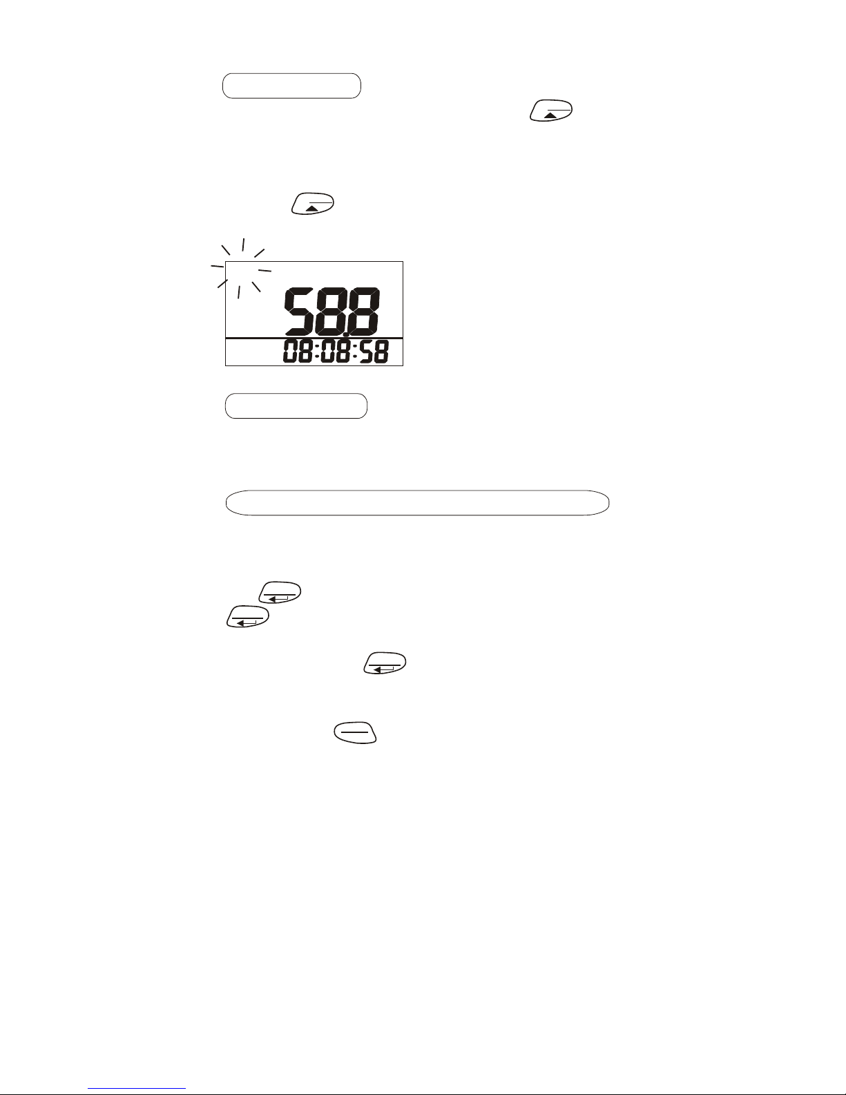
STEL, TWA and current value in turns.
Each press of displays MIN, MAX,
STEL, TWA, current value in sequence.
(Fig.10~12). To return to normal mode,
press the
START
key to escape (Fig.13).
CURRENT MIN,MAX,STEL,TWA REVIEW
This meter allows you to check the
minimum, maximum, STEL, TWA and
current value from the moment you pres
s
the
M X/AVG
key. Under normal mode, press
BACKLIGHT
The backlight will be activated for 10
seconds by pressing any key.
DATA HOLD
In normal display mode, press
HOLD
to
freeze the readings, "HOLD” icon is
flashed on the left top of LCD(Fig.9). Al
l
current readings are kept unchanged.
Press
HOLD
again to cancel the hold
function.
Fig.9
N
M
X/AVG
N
to see the minimum, maximum,
M
X/AVG
N
ESC
If the meter is turned on for shorter than
15 mins, the STEL and TWA values will b
e
the weighted average of readings take
n
since power on. The actual TWA value
s
will appear after 8 hours.
It takes at least 5 mins to calculate STE
L
and TWA. The display will show “----”
during the first 5 minutes after power on.
While in “HOLD” mode, STEL and TWA
will update every 5 mins.
7
HOLD
%rh
AM
Page 9
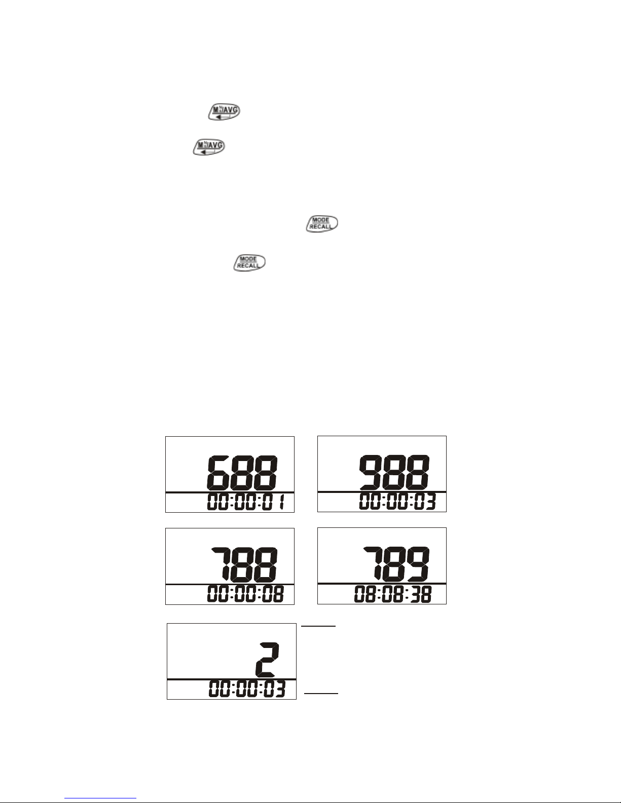
The m eter also
allows you to check the
min/max/STEL/TWA v alues calcul ated
since power on. Under normal mode
press to see min/max/STE L/TWA
and real time sequence. Each pr ess of
the displa ys the sequen ce in turn,
then returns to the current mode
(Fig.10~13).
STEL and TWA are calculated for CO2 only.
In this mode, press to switch the
displayed parameters (Fig 14).
Press the key to leave this mode and
return to normal mode.
You can tell between the normal display
and current review by checking the time
display format. In normal display, the
date & time display in turns. In current
review, the time display is the
accumulated time of how long you are i
n
max/min mode.
Fig.11
Fig.10
Fig.13
Fig.12
NOTE:
“MANUALY RECORD &
“RECALL” FUNCTIONS
ARE DISABLED IN
MIN/MAX/AVG MODE.
NOTE:
TWA & STEL ARE FOR
CO2 ONLY.
MIN/MAX ARE FOR ALL
PARAMETERS.
Fig.14
8
CO
MAX
CO
2
AM
CO
2
CO
2
T
WA
CO
2
Page 10
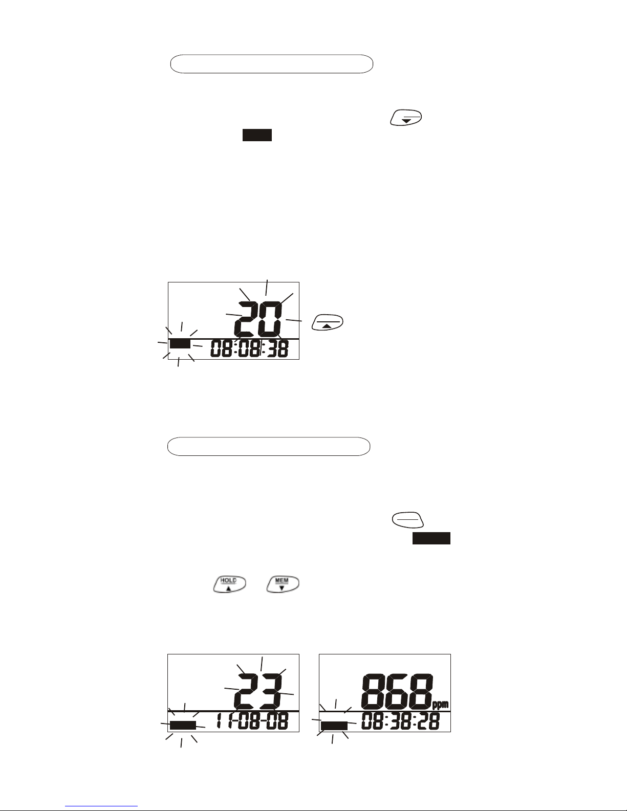
RECORDING DATA
The meter features a 99 point memory.
In normal or hold mode, Press
MEM
key
to record.
icon and main display
flash for about 3 seconds. The main
display shows the memory serial number
up to 99 points ((Fig. 15).
Each memory contains all parameters
(CO2, CO, TA.....%RH), not only the
parameter you choose to see on the main
display.
If the reading change
s
quickly, you can press
HOLD
to freeze the
reading before
manually recording
Fig.15
the data.
The manually recording function is
disabled in min/max mode.
99 MEMORY RECALL
The meter has 99 memor y locations
that can be saved and reviewed.
In normal or hold mode, press
MODE
key
RECALL
for more than 2 seconds until the
icon flashes.
Press or to scroll through the
memories. The memory serial number
displays on the main LCD first and readings
come after (Fig.16 & 17).
Rec al l
Rec al l PM
Fig.16
Fig.17
9
CO
2
Re ca ll
TA
REC
AM
REC
Page 11
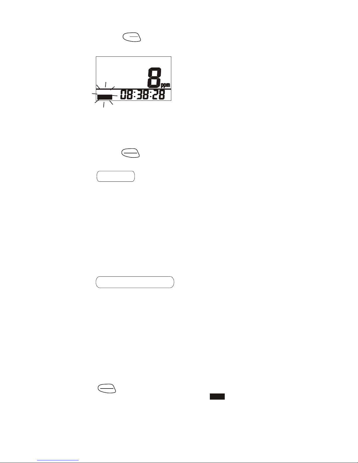
Press
MODE
key to switch the display
RECALL
parameter (Fig.18).
Fig.18
Rec al l PM
The time displayed in memory recall
mode is the recording time of this
memory.
To leave the memory recall mode,
press
ESC
key to exit and return to
the
normal display.
ALARM
The meter features an audible alarm to
give warnings when CO concentration
exceeds the limit. (See P.20 in setup
for setting alarm threshold). It emits
beeps (approx. 80db) if the CO level
goes over the set value and stops only
when the readings fall below the set
value. It beeps again if the value goes
over the limit.
DATA LOGGING
The meter can automatically record
readings of CO2/CO/TEMP/RH for long
time environment monitoring. The
memory capacity is 8,000 points. Users
can set that sampling rate from 1 second
to 4 hours 59 minutes and 59 seconds
(See SETUP Section).
START
After sampling rate is selected, press
for 2 seconds under normal
START
ESC
mode to start logging. The
REC
icon
flashes to indicate the logging status
and LCD main display shows the real
time CO
2 value. Lower displays are th
e
real time clock (Fig.19).
10
CO
Page 12
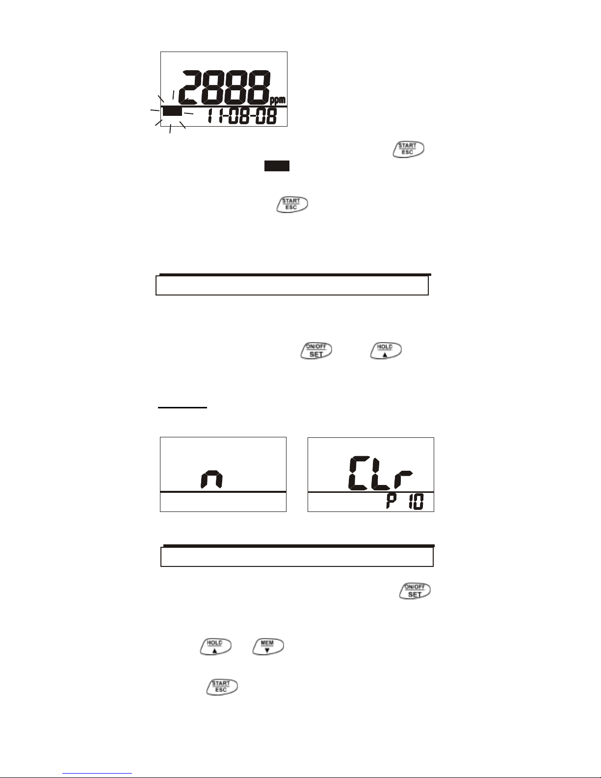
Fig.19
To terminate data logging, press
for 2 seconds,
REC
icon stops flashing.
The meter will only record one session
at a time. Once
REC
record mode is
activated all previous data is erased.
Download logged data on a PC
prior to
recording another data log.
The meter turns off automatically after
20 minutes of inactivity. To override th
e
function, hold down and at
the same time for 2 seconds until “n”
appears (Fig.20).
NOTE: AUTO POWER OFF IS
DISABLED DURING CALIBRATION.
Fig.20
Fig.21
When the meter is off, hold down
for more than 1 second to enter setup
mode.
Press or to scroll through the
setup options.
Press to exit setup mode.
11
SETUP
AUTO POWER OFF
CO
2
REC
Page 13
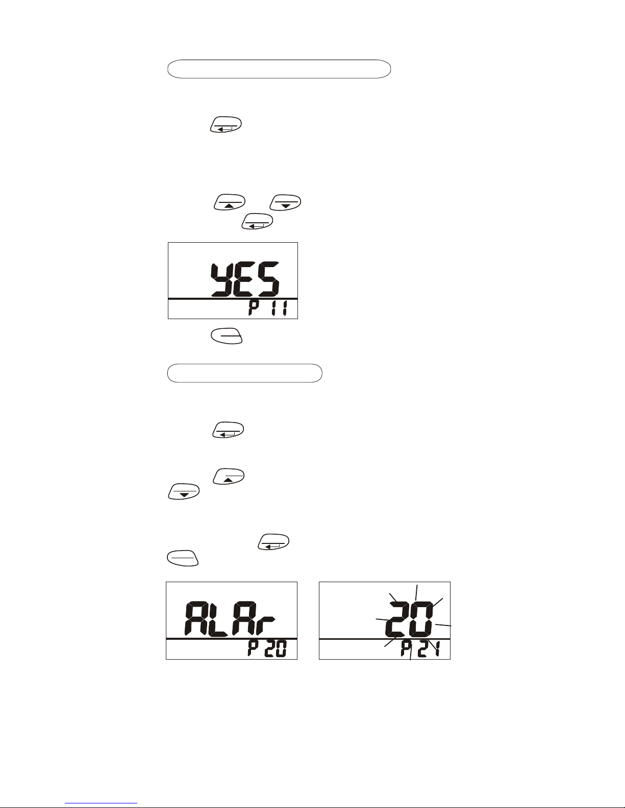
P10 CLEAR MEMORY
When entering setup mode, P10 and
“CLr” (Fig.21) are displayed on the LCD.
Press
N
to go into P11 and decide to
M
X/AVG
clear or keep all the manual records.
The current set will be blinking on LCD
(Fig.22).
Press or to choose NO or YES
HOLD MEM
and press
N
to confirm.
M X/AVG
Fig.22
Press
START
to return to P10.
ESC
P20 CO ALARM
When entering setup mode, P20 and
“ALAr” (Fig.23) are displayed on LCD.
Press
N
to go into P21 and set the
M
X/AVG
CO alarm threshold. The current set
value will blink on the LCD (Fig.24).
Press
HOLD
to increase the value or
MEM
to decrease. The selectable alarm
limits are 15~200ppm. Each press is
5ppm. When the preferred alarm value
is set, press
N
to save the setting or
M
X/AVG
START
without saving and return to P20
ESC
Fig.23
Fig.24
12
CO
CO
Page 14
Press
START
to return to P30.
P30 TEMPERATURE UNITS
When entering setup mode, P30 and
“unit” (Fig.25) are displayed on the LCD.
Press
N
to go into P31 and select the
M
X/AVG
temperature units in 0C or 0F.
The current set will display on LCD
(Fig.26).
Press
HOLD
or
MEM
to pick 0C or 0F
and press
M
X/AVG
N
C
Fig.25
Fig.26
ESC
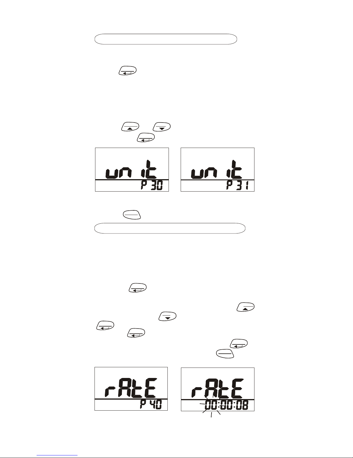
P40 LOGGING SAMPLING RATE
Go into P40 for setting sampling rat
e
of data logging (Fig.27). The range
is from 1 second to 4 hours 59
minutes and 59 seconds.
N
Press
M
X/AVG
and it goes into setting
with blinking Hour digits on the lower
display. To change the digit, press
HOLD
to increase and
MEM
to decrease. Press
to confirm and enter Minute setting.
M
X/AVG
N
N
Press
M
X/AVG
again to confirm and ente
Second setting (Fig.28). Press
to confirm the rate setting or
N
M X/AVG
START
ESC
without saving and return to P40.
Fig.27
Fig.28
13
TA
O
TA
Page 15
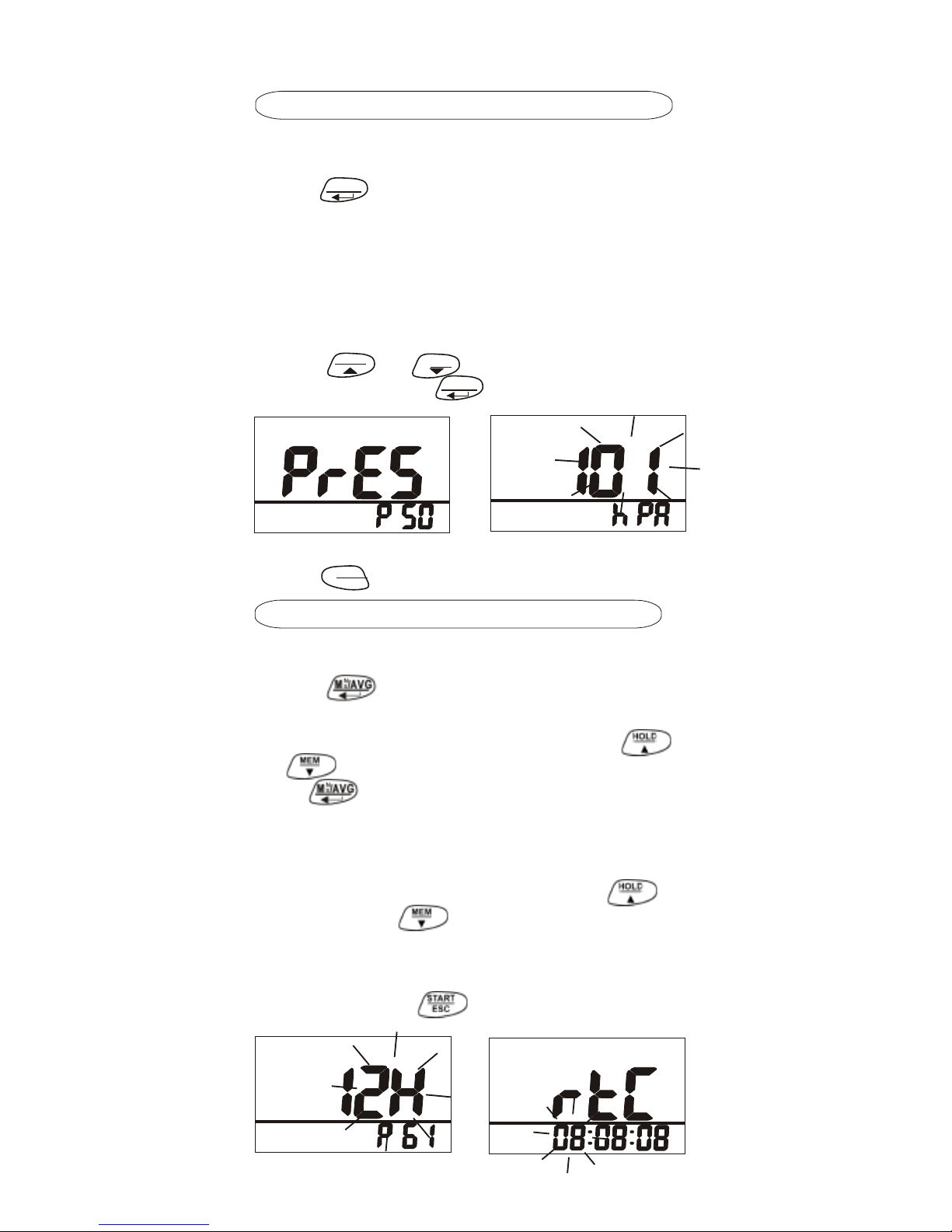
P50 PRESSURE COMPENSATION
When entering setup mode, P50 and
“PrES” (Fig.29) are displayed on the LCD.
Press
N
to set pressure compensation
M
X/AVG
value for CO2 measurement.
The current set will flash on LCD
(Fig.30).The barometric pressure uni
t
is kpa.
Press
HOLD
or
ME
M
to adjust the pressure
value and press
to confirm.
M
X/AVG
N
Fig.30
Fig.29
Press
START
to return to P50.
ESC
P60 REAL TIME CLOCK
Go into P60 to set the real time clock.
Press to enter into P61 to set the
time format as 12 or 24 hour. The current
setting will flash on the LCD. Press
or to change the format and press
the key to confirm.
NOTE: Date format is YY/MM/DD
The date will show on the lower display
with the year digit blinking. Press
to
increment or to decrement the
digits.
Use the same process to set the month
and day. Press to return.
Fig.31
Fig.32
14
PM
CO
2
CO
2
Page 16
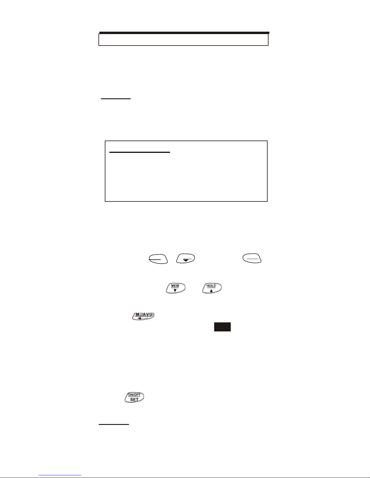
The meter is calibrated at standard
400ppm CO2 concentration at the
factory. You should manually calibrate
regularly to maintain good accuracy.
NOTE:
When accuracy becomes a concern afte
r
long use, you can return the meter to
CO2Meter, Inc. for standard calibration.
For succes sful manual calibration, it
should only be completed
with the meter
located i n fresh, outdoor air. Start with
the unit powered off.
First press
START
+
MEM
then also
ON/OFF
SET
ESC
simultaneously for 3 seconds to turn on
the meter and enter calibration mode
(Fig.33).
Press or to choose
from humidity, CO or CO2 calibration
menus.
Press
key to select the
calibration. 400ppm and
icon
will blink on the screen.
(Fig.34).
Wait about 10 minutes until the blinking
stops and the calibration is completed
automatically. To abort the calibration,
press at any time.
NOTE:
Ensure the batteries are fully charged or
meter is plugged in during calibration to
prevent interrupted or failed calibration.
15
CAL
IMPORTANT:
Do not calibrate the meter in air wit
h
an unknown CO2 concentration.
Otherwise, it will be calibrated as
400ppm by default which will lead
to inaccurate measurements.
CO2 CALIBRATION
Page 17
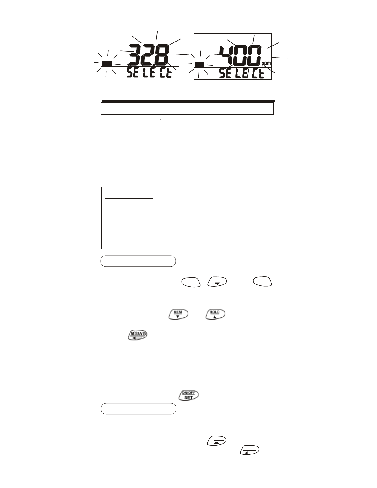
Fig.33
Fig.34
The meter defaults to be calibrated the
humidity with 33% and 75% salt solution
.
The ambient condition is recommended
to be at 25oC and stable humidity(better
to be close to the calibrating value). To
abort calibration, just turn off the meter.
33% calibration
Plug the sensor probe into 33% salt
bottle. First press
START
+
MEM
, also
ON/OFF
SET
ESC
simultaneously for 3 seconds to turn on
the meter and enter calibration mode
(Fig.33).
Press or to choose
the 33% humidity calibration menu.
Press to select 33% calibration
(32.8% if at 25
o
C) and to start.
Meter is now calibrating, and will finish
in about 60 minutes when “CAL” and
humidity stop blinking. To abort
calibration, press at any time.
75% calibration
Plug the sensor probe into 75% salt
bottle and enter calibration mode. In
calibration mode, press
HOLD
to select
75% calibration (Fig.35), press to
begin.
M X/AVG
N
16
CAUTION:
Do not calibrate the humidity without
the default calibration salt. Otherwise
,
it will cause permanent damage.
Contact CO2Meter, Inc. for calibration
salt or services.
RH CALIBRATION
CO
2
CAL
%rh
CAL
Page 18
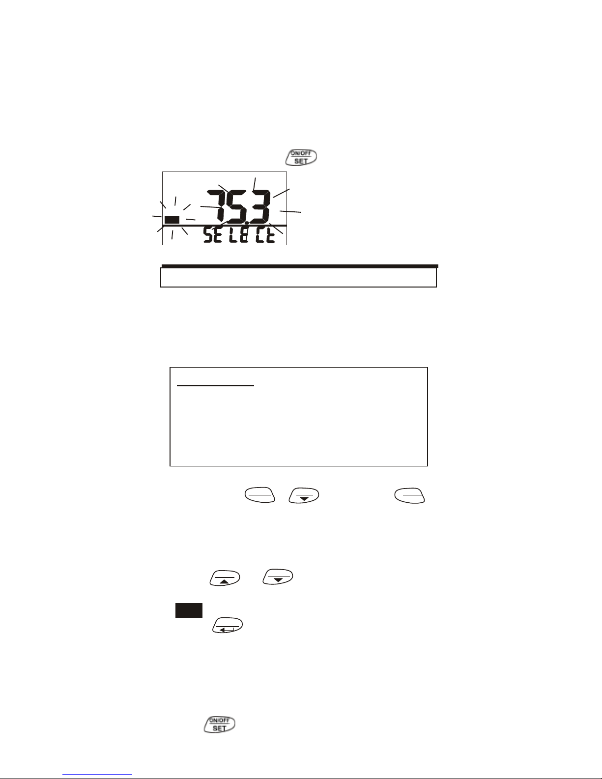
“CAL” and calibrating value (75.3% if at
25oC) are blinking on the LCD.
Meter is now calibrating, and will finish
in about 60 minutes when “CAL” and
humidity stop blinking. To abort
calibration press at any time.
Fig.35
CAL
When the accuracy becomes a concern
after a long time usage, return to dealer
s
for standard calibration. It is necessary
to have standard CO gas for calibration.
Place the meter in the calibration site.
First press
START
+
MEM
then also
ON/OF
ESC
SET
simultaneously for 3 seconds to turn on
the meter and enter calibration mode
(Fig.33).
Press
HOLD
or
MEM
to select the CO
0ppm or 400ppm calibration. ppm and
“
Press
“ icon will blink on the LCD.
to start the calibration
M
X/AVG
N
(Fig.36 & 37).
Wait about 10 minutes until the blinking
stops and the calibration is completed
automatically. To abort the calibration,
press at any time.
17
CAL
CAUTION:
Do not calibrate the meter in the ai
r
with unknown CO concentration.
Otherwise, it will be calibrated as
0 or 400ppm by default and leads t
o
inaccurate measurements.
CO CALIBRATION
%rh
Page 19
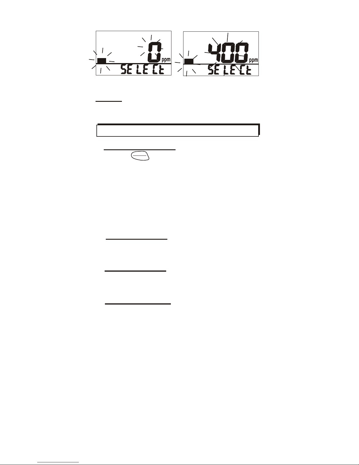
Fig.36
Fig.37
NOTE: 400ppm calib ration gas c an
vary from 385~415ppm (400+15ppm)
? Cannot power on
-Press
SET
for more than 3 seconds
ON/OFF
and try again.
-
Check whether batteries are in good
contact and correct polarit
y, or the
adaptor is plugged in correctly.
-You may also take out the batteries for
10 mins and then put them back in
again.
? Fixed readings
Check whether data hold is activated.
(HOLD icon displayed)
? Slow response
Check whether the air flow channels on
the rear are blocked.
? Error messages
E01/E33: CO2 sensor is out of order. Try
new battery first.
E02: The value is under range.
E03: The value is over range.
E04: The original data error results in
this error (DP, WB)
E11: Retry humidity calibration.
E16: Retry CO calibration.
E31: Temperature sensor or
AD damaged.
E32: Memory IC damaged.
E33: Humidity sensor or circuit damaged.
18
TROUBLESHOOTING
CO
CAL
CO
CAL
Page 20
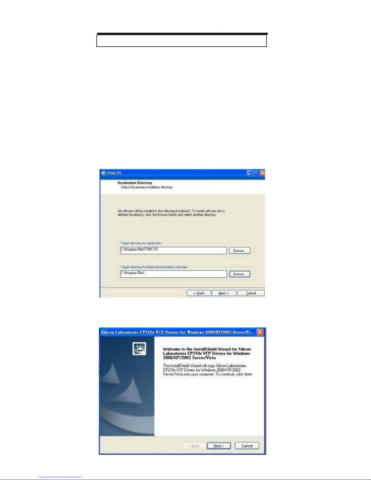
Connect the logger to PC, users can do
logging setting and data transmission
with the included software.
Plug the USB cable into the socket at
the right side of the meter and the othe
r
port to PC. Then install the software i
n
your PC with the following procedure.
1.Insert the CD Rom and run installation.
Select a preferred directory and click
“Next” step by step and finish it.
2. After the software installation is
completed, it will run USB drive
r
installation next.
19
PC CONNECTION
Page 21
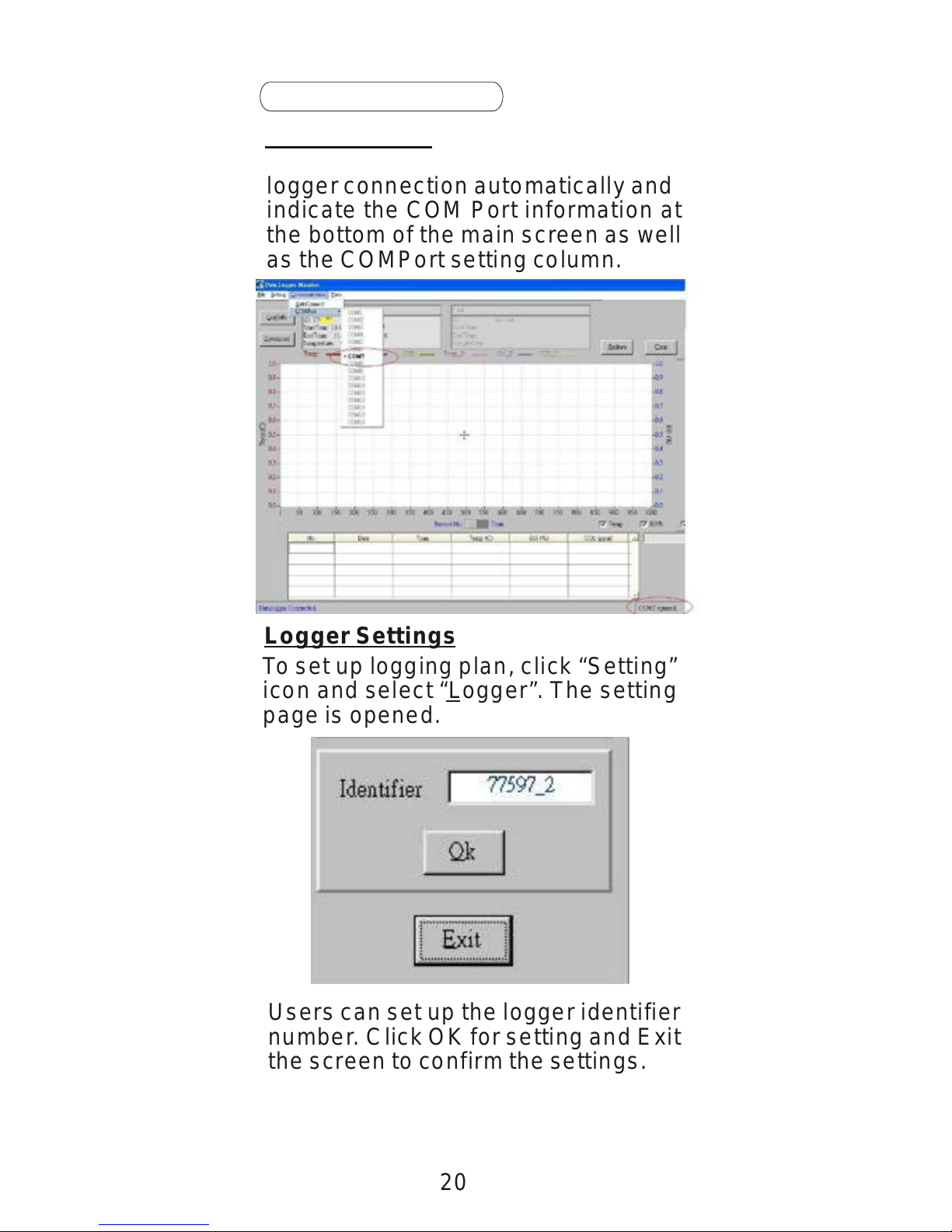
logger connection automatically and
indicate the COM Port information at
the bottom of the main screen as well
as the COMPort setting column.
Logger Settings
To set up logging plan, click “Setting”
icon and select “Logger”. The setting
page is opened.
Users can set up the logger identifier
number. Click OK for setting and Exit
the screen to confirm the settings.
20
Software Operation
Auto-Connect
Start the software and it will detect
Page 22

Data Transmission
To transmit auto recorded data from th
e
meter, click “Download” icon on the lef
t
top side of the main screen. All autorecorded data in the logger will be
transmitted. The raw data with time
stamp will display at the lower part of
the screen and the graph in the middle.
In the Graph display, the Y-axis indicates
Temp, RH, DP, WBT, CO2 & CO level in
different line colors. And the X-axis can
be switched to show Time or Record
number stamp.
Data Review Function
The following functions help to view
the GRAPH data in more detailed way.
Under View function, there are 4 tools
to enlarge the Graph data for detaile
d
data review.
Zoom in: Hold down “Ctrl” key on the
PC keyboard and click any target point
on the graph. It enlarges the point in
each click.
21
Page 23
Zoom window: Hold down “Ctrl” key and
drag click the left button of the mouse to
select an area on the Graph and the
selected area will be enlarged.
Zoom X-axis: Hold down “Ctrl” key and
drag click the left button of the mouse to
select an area on the Graph and the
X-axis of the selected area will be
enlarged.
Zoom Y-axis: Hold down “Ctrl” key and
drag click the left button of the mouse t
o
select an area on the Graph and the
Y-axis of the selected area will be
enlarged.
Three icons on the right top side of the
main screen:
Redraw: After any review and zooming
on the Graph, click “Redraw” to reset i
t
to original format.
Clear: Click “Clear” to delete all data
and Graph on the window. A warnin
g
box shows up for confirmation. Pres
s
“Yes” and all data will be cleared.
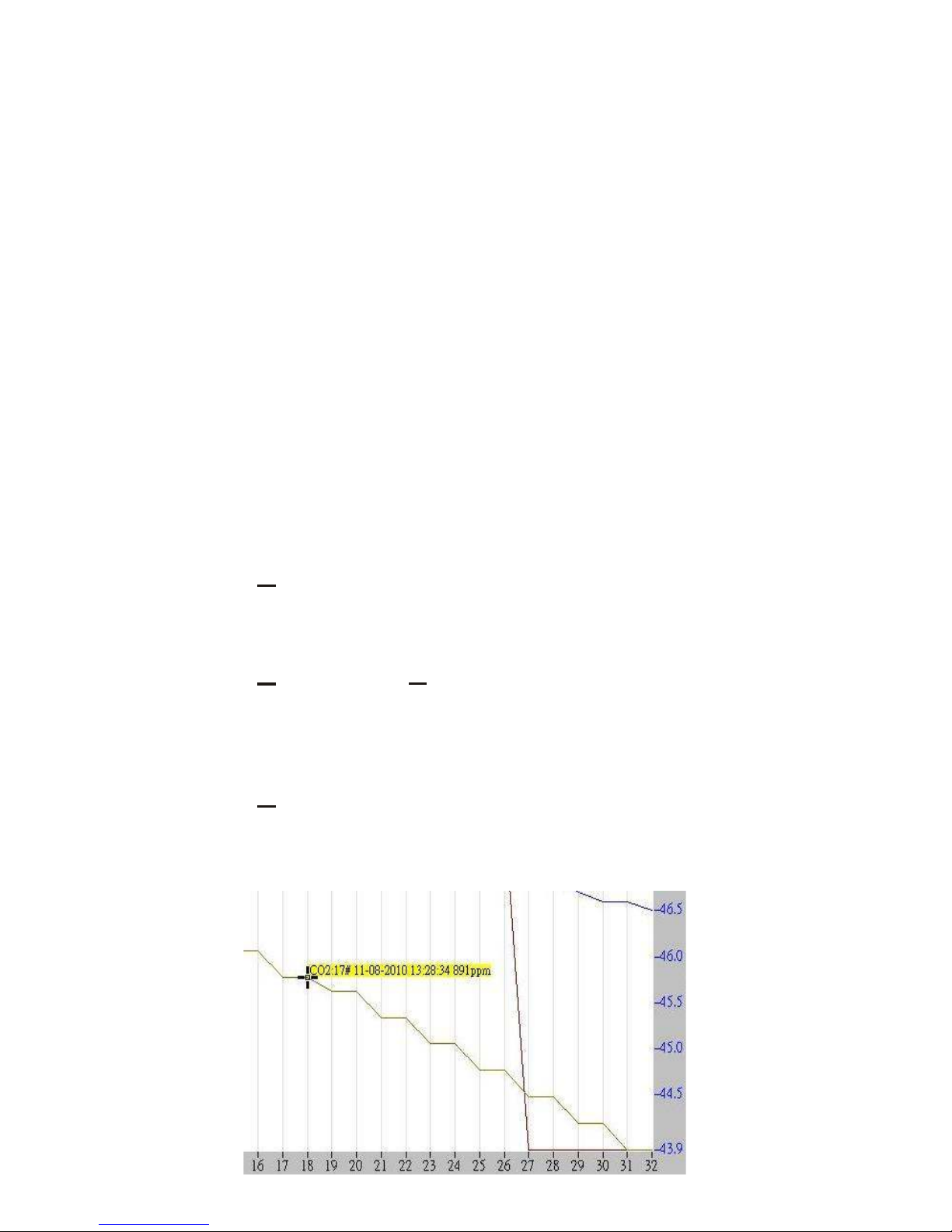
Cursor: Switch Cursor ON and it shows
the raw data with the cursor. In any clic
k
on the graph, the digital data displayed
.
Switch OFF to disable the function.
22
Page 24
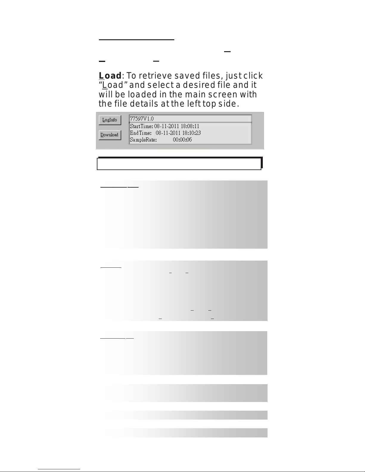
Load: To retrieve saved files, just click
“Load” and select a desired file and it
will be loaded in the main screen with
the file details at the left top side.
Data Processing
The downloaded data can be Saved or
Printed via “File” processing functions.
77597
0~9999 p pm,
(5001~9999 p pm o ut o f s cale r ange)
0~1000 p pm,
Measuring r ange
CO2
CO
Temperature
Relative H umidity
-20~60oC ( -5~140oF)
0.1%~99.9%RH
-20.0~59.9oC
-5.0~59.9oC
1ppm
, 0
.1oC/oF, 0 .1%RH
DP(Dew p oint t emp.)
WB(Wet b ulb t emp.)
Resolution
Accuracy
CO2
+30ppm+5% o f r eadin g
(
0 ~5000ppm)
Other r anges a re n ot s pecif ie d
+/- 10 ppm fo r le ss th an 100 ppm
+/- 10% or readin g fo r 101~500 ppm
+/- 20% of readin g fo r 501ppm and above
+0.6oC/+0.9oF
+3%RH
(at 2 5oC, 1 0~90%RH) ;
+ 5%RH
( a t 2 5oC , o th er r ange
)
30 s econds
CO
Temperature
Relative H umidity
CO2 Warm-up t ime
Response t ime
CO2
CO
Tair
RH
LCD / Mete r siz e (mm
)
Operating c ondition
(avoid c ondensation)
Storage c ondition
Power s upply
Battery l ife
Weight
<30 s econds(90% s tep c hange)
<60 s econds(90% s tep c hange)
<2 m ins
(90% s tep c hange)
<10 m inutes ( 9 0% s tep c hange)
26(H)x44(L), 205(L)x70(W)x56(H)
-20 t o 5 0 ° C ( CO2 s ensor),0 t o 5 0 ° C ( CO s ensor)
-20 t o 6 0 ° C ( for t he r est p arameters)
-20~ 6 0oC,10~90%RH(avoid c ondensation)
AA
x 4
pcs o r 9 V a daptor
> 2 4 h ours ( Alkaline b attery)
200g
Standard p ackage
Meter, m anual , AA b at.,USB c able & CD, c arry c ase
23
SPECIFICATIONS
Page 25

Non-Enforced Reference levels
NIOSH recommendations
400 ppm: normal outdoor ambient air
CO2 concentrations
600 ppm: normal indoor air quality
1,000+ ppm: indicates inadequate
ventilation; complaints such as
headaches, fatigue, and
eye/throat irritation will be more
widespread. 1000 ppm should b
e
used as an upper limit for indoor
levels.
EPA Taiwan: 600ppm and 1,000ppm
Type 1 In indoor areas such as department
stores, theaters, restaurants, libraries
the acceptable CO
2 concentration of 8
hours average (TWA) is 1,000ppm.
Type 2 indoor areas with special requirement
s
of good air quality such as schools,
hospitals, day care centers, the
suggested CO2 level is 600ppm.
Regulatory Exposure Limit
ASHRAE Standard 62-1989: 1,000ppm
CO2 concentrations in occupied buildings
should not exceed 1,000ppm.
Building bulletin 101 (BB101): 1,500ppm
UK standards for schools say that CO
2
levels averaged over the whole day (TWA, i.e
.
9am to 5pm) should not exceed 1500ppm.
OSHA: 5000ppm
Time weighted average over five 8-hour work
days should not exceed 5,000ppm.
Germany, Japan, Australia, UK: 5,000ppm
8 hours weighted average in occupational
exposure limit is 5,000ppm.
24
CO2 LEVELS AND GUIDELINES
Page 26
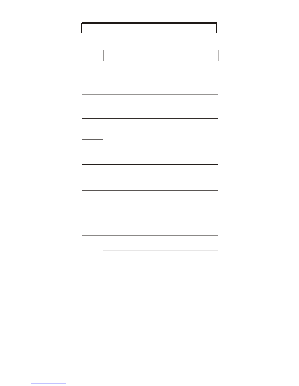
ppm
Symptoms and applicable standard
Maximum allowable concentration per
62-1989 for
living area.
exposure per California OSHA
level per US OSHA workplace standards.
exposure in any 8 hrs average level per
space if the CO concentration exceeds
dizziness w/i 2-3 hrs.
after 3hrs. Maximum concentration
standards.
w/i 2-3 hrs.
25
0-1
Normal background levels
9
Maximum indoor air quality level:
ASHRAE Residential standards
25
Maximum limit 8 hrs of continuous
workplace standards.
35
Maximum 8 hrs average exposure
50
Maximum concentration for continuous
OSHA standards.
100
Remove employees from enclosed
100ppm per OSHA exposure limit.
20 0
Mild headache, fatigue, nausea and
40 0
Frontal headache, life threatening
in flue gas per the US EPA and AGA
80 0
Dizziness,
nausea,
convulsions,
death
1600
Nausea w/i 20 min.,death w/i 2-3 hrs
CO LEVELS AND GUIDELINES
Page 27

The meter comes with a one (1) year
warranty starting from the date the
meter was shipped to the bu ye r.
During this period of time, CO2Meter
warrants our products to be free from
defects in materials and workma nsh ip
when used for their intended purpose,
and agrees to fix or replace (at our
discretion) any part or product that fails
under normal use. To take advantage
of this warranty, the product must be
returned to CO2Meter.com at your
expense. If, a fter examination, we
determine the product is defectiv e, we
will repair or replace it at no add itional
cost to you.
This warranty does not cover any
products that have been subje cted to
misuse, neg lect, accident,
modifications or repairs by you or by a
third party. No employee or reseller of
CO2Meter.com’s produ ct s ma y alter
this warranty verbally or in writing.
All liabi lities under this agreement shall
be limited to the actual cost of the
product paid to CO2Meter.com. In no
event shall CO2Meter.com be l iable
for any incidental or consequential
damages, lost profits, loss of time, lost
sales or loss or damage to data, injury
to person or personal property or any
other indirect damages as the result of
use of our products.
26
LIABILITY
WARRANTY
Page 28

If the product fails under normal use
during the warranty period an RMA
(Return Material Authorization) number
must be obtained from CO2Meter.com.
After the item is received,
CO2Met e r. c o m w il l rep a i r or re p la ce
the item at our discretion.
To obtain an RMA number, call us at
(386) 256-4910 or email us at
. When
requesting an RMA number, please
provide the reason for return and the
original order number
If we determine that the product has
failed because of improper use (wate r
damage, dropping, tampering,
electrical damage, etc.) or if it beyond
the warranty date, we will inform you of
the cost to fix o r replace the product.
For more inform atio n vi sit our w e bsite:
www.CO2Meter.com/pages/faq
Contact us: We’re here to help!
If the troubleshooting guide above
doesn’t help you solve your problem or
for more information, please contact us
using the information below.
(386) 256
-4910 Technical Support
(386) 872
-7665 Sales
27
RETURN AUTHORIZATION
 Loading...