

Page 1
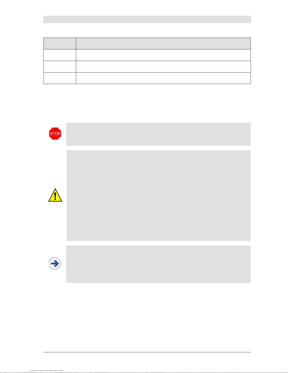
Page 2

Edition: November 7th 2012 Version: 3.5.1, PN: 21-FHZU-10002
The CNAP™ Monitor 500 meets the requirements of -mark
0408
according to the European standard for medical devices 93/42/EWG, annex IX
as amended by 2007/47/EC
The product starting with the serial number 0500-0917-xxxx was voluntarily tested according to
UL 60601-1:2003, CAN/CSA C22.2 No.601.1-M90
This manual refers to the following configuration:
Hardware: CNAP™ Monitor 500i and CNAP™ Monitor 500at (note that only the
CNAP™ Monitor 500at comes with a functional analog output port)
Software: Version 3.5R01
CNSystems Medizintechnik AG
Reininghausstrasse 13
8020 Graz
Austria
T: +43 (0) 316 7 23456-0
F: +43 (0) 316 7 23456-2
E-mail: [email protected]
I: www.cnsystems.at
Page 3

Table of contents
CNAP™ Monitor 500 Page i Version 3.5.1, PN: 21-FHZU-10002
Table of contents
1 About this manual..........................................................................................................1-1
1.1
STOP, CAUTION, NOTES..........................................................................................1-1
1.2
Cross references.....................................................................................................1-1
1.3
Settings ................................................................................................................1-1
2 General information .......................................................................................................2-1
2.1
Warnings...............................................................................................................2-1
2.2
Precautions............................................................................................................2-1
2.2.1 General precautions .....................................................................................2-1
2.2.2 Blood pressure ............................................................................................2-2
2.3
Disposal ................................................................................................................2-3
2.4
Declaration of intended use .....................................................................................2-3
3 Introduction ..................................................................................................................3-1
3.1
General information ................................................................................................3-1
3.2
System components ...............................................................................................3-1
3.2.1 CNAP™ Monitor 500.....................................................................................3-2
3.2.2 CNAP™ hardware.........................................................................................3-5
3.2.3 NBP cuff .....................................................................................................3-6
3.3
Power supply .........................................................................................................3-7
3.3.1 Mains operation...........................................................................................3-7
3.3.2 Battery operation ........................................................................................3-7
3.4
First steps ........................................................................................................... 3-10
3.4.1 Power On/Off ............................................................................................ 3-10
3.4.2 Access/return to main screen ......................................................................3-11
3.4.3 Fast access keys........................................................................................ 3-12
3.4.4 Menu navigation – click-wheel control .......................................................... 3-13
3.4.5 Menu selection ..........................................................................................3-13
3.5
Patient setup .......................................................................................................3-14
3.6
Timer..................................................................................................................3-15
3.7
Perfusion Index .................................................................................................... 3-16
4 Monitor configuration .....................................................................................................4-1
4.1
Monitor settings .....................................................................................................4-1
4.2
Measurement settings .............................................................................................4-1
4.3
Service settings......................................................................................................4-2
4.4
BP Wave Out (patient monitors) ...............................................................................4-2
4.4.1 BP Wave Out configuration ...........................................................................4-2
4.4.2 Compatibility list..........................................................................................4-3
4.4.3 Zeroing ......................................................................................................4-4
4.5
Interfaces (optional) ...............................................................................................4-6
4.5.1 AUX Analog Out (analog output port) .............................................................4-6
4.5.2 Ethernet .....................................................................................................4-6
4.5.3 USB ...........................................................................................................4-6
5 Management of patient data............................................................................................5-1
5.1
Patient entry..........................................................................................................5-1
5.2
Editing of patient data.............................................................................................5-3
Page 4

Table of contents
CNAP™ Monitor 500 Page ii Version 3.5.1, PN: 21-FHZU-10002
5.3
Discharge ..............................................................................................................5-3
6 Alarm system ................................................................................................................6-1
6.1
Visual alarm signals ................................................................................................6-2
6.2
Acoustic alarm signals.............................................................................................6-3
6.3
Alarm system control ..............................................................................................6-4
6.3.1 Acknowledgement of alarms – Audio Off, Audio Pause......................................6-4
6.3.2 Pausing/switching off alarms – Alarms Paused, Alarms Off................................6-4
6.3.3 Reactivation of paused alarms - Alarms Off.....................................................6-5
6.4
Alarm limits ...........................................................................................................6-5
6.4.1 Display of individual alarm limits ...................................................................6-5
6.4.2 Alarm setup ................................................................................................6-5
6.4.3 Auto limits ..................................................................................................6-7
6.4.4 Alarm limits – factory settings.......................................................................6-7
6.5
Alarm history .........................................................................................................6-8
6.6
Alarm system function tests.....................................................................................6-9
6.7
Physiological alarms................................................................................................6-9
7 Trends..........................................................................................................................7-1
7.1
Trend – the menu for display options ........................................................................7-2
7.2
Setup....................................................................................................................7-3
7.2.1 Trend views ................................................................................................7-3
7.2.2 Graphic trend..............................................................................................7-3
7.2.3 Numeric trends ...........................................................................................7-6
7.2.4 Alarm history ..............................................................................................7-7
7.2.5 Scrolling of trend views ................................................................................7-8
8 Printing ........................................................................................................................8-1
8.1
Launching print reports ...........................................................................................8-1
8.2
Canceling print reports............................................................................................8-2
8.3
Print reports ..........................................................................................................8-2
8.4
Print options ..........................................................................................................8-3
9 CNAP™ .........................................................................................................................9-1
9.1
General information ................................................................................................9-1
9.2
Safety precautions..................................................................................................9-2
9.3
Setup....................................................................................................................9-3
9.4
View features.........................................................................................................9-4
9.4.1 Blood pressure waveform .............................................................................9-4
9.4.2 Trend view..................................................................................................9-4
9.4.3 Numeric values ...........................................................................................9-5
9.5
CNAP™ options ......................................................................................................9-6
10 NBP............................................................................................................................10-1
10.1 General information ..............................................................................................10-1
10.2 Venous stasis.......................................................................................................10-2
10.3 Safety precautions................................................................................................10-3
10.4 Setup..................................................................................................................10-4
10.5 View features....................................................................................................... 10-6
10.6 NBP options ......................................................................................................... 10-7
11 Cleaning and disinfection ..............................................................................................11-1
Page 5

Table of contents
CNAP™ Monitor 500 Page iii Version 3.5.1, PN: 21-FHZU-10002
11.1 General precautions..............................................................................................11-1
11.2 Cleaning..............................................................................................................11-1
11.3 Disinfection..........................................................................................................11-2
12 Technical alarms and status messages ........................................................................... 12-1
12.1 Main unit ............................................................................................................. 12-2
12.1.1 Status messages .......................................................................................12-2
12.1.2 Technical alarms........................................................................................12-2
12.2 BP Wave Out (IBP) ............................................................................................... 12-3
12.2.1 Status messages .......................................................................................12-3
12.2.2 Technical alarms........................................................................................12-3
12.3 Printer ................................................................................................................ 12-4
12.3.1 Technical alarms........................................................................................12-4
12.4 CNAP™................................................................................................................ 12-4
12.4.1 Status messages .......................................................................................12-4
12.4.2 Technical alarms........................................................................................12-5
12.5 NBP .................................................................................................................... 12-8
12.5.1 Status messages .......................................................................................12-8
12.5.2 Technical alarms........................................................................................12-9
13 Appendix A – Glossary..................................................................................................13-1
13.1 Illustrations ......................................................................................................... 13-2
14 Appendix B – Accessories..............................................................................................14-1
14.1 CNAP™................................................................................................................ 14-1
14.2 NBP .................................................................................................................... 14-1
14.3 Printer ................................................................................................................ 14-2
14.3.1 Paper recommendation............................................................................... 14-2
14.4 Connections......................................................................................................... 14-2
14.5 Other accessories .................................................................................................14-2
15 Appendix C – Technical specifications .............................................................................15-1
15.1 CNAP™ Monitor 500.............................................................................................. 15-1
15.1.1 External mains adapter ..............................................................................15-2
15.1.2 CNAP™ - continuous non-invasive arterial pressure .......................................15-3
15.1.3 NBP - non-invasive blood pressure............................................................... 15-3
15.1.4 Printer...................................................................................................... 15-4
15.2 Connections......................................................................................................... 15-4
15.3 Electromagnetic compatibility................................................................................. 15-6
15.4 Maintenance schedule ........................................................................................... 15-9
15.4.1 Safety inspection ....................................................................................... 15-9
15.4.2 Maintenance ........................................................................................... 15-10
15.5 Standards.......................................................................................................... 15-10
15.6 Declaration of conformity .................................................................................... 15-11
Page 6
About this manual
CNAP™ Monitor 500 Page 1-1 Version 3.5.1, PN: 21-FHZU-10002
1 About this manual
STOP, CAUTION, NOTES.........................................................................................................1-1
Cross references ...................................................................................................................1-1
Settings ...............................................................................................................................1-1
1.1 STOP, CAUTION, NOTES
In this manual the icons "STOP", "CAUTION", and "NOTE" are used to indicate matters of particular
interest to keep in mind when operating the CNAP™ Monitor 500 or dealing with patients.
STOP
The STOP icon indicates important security-relevant information:
STOP:
• Check the correct positioning of the CNAP™ double finger cuff. Make sure that the cuff
is not positioned on the finger joints.
CAUTION
The CAUTION icon indicates important information referring to the correct utilization of the CNAP™
Monitor 500:
CAUTION:
• The lifetime cycle of a CNAP™ double finger cuff is 6 months if in constant use on pa-
tients, or 12 months at the most.
NOTE
The NOTE icon indicates helpful information referring to the utilization of the CNAP™ Monitor 500 and
its components:
NOTE:
• Use the graphics on the CNAP™ controller to determine the correct finger cuff size.
• If the size of a patient's finger is between two finger cuff sizes, use the larger CNAP™
finger cuff for the measurement.
1.2 Cross references
Cross references refer to chapters where the operator can find additional information about specific
topics. A cross reference includes the number and title of the chapter referred to (e.g. see chapter 2 –
General information).
1.3 Settings
Settings available for menu entries are listed as:
Menu item Description Setting
Brightness
Regulates the brightness of the TFT-display
20(20)100, Auto
Minimum (Increment) Maximum
Page 7

General information
CNAP™ Monitor 500 Page 2-1 Version 3.5.1, PN: 21-FHZU-10002
2 General information
Warnings..............................................................................................................................2-1
Precautions ..........................................................................................................................2-1
General precautions ..............................................................................................................2-1
Blood pressure......................................................................................................................2-2
Disposal ...............................................................................................................................2-3
Declaration of intended use ....................................................................................................2-3
2.1 Warnings
• The CNAP™ Monitor 500 is not designed for intracardial use.
• Do not connect the device's air connectors to an intravascular system!
• Do not use the oscillometric cuff on patients with vascular prostheses!
• Keep the CNAP™ Monitor 500 out of reach of children!
• The CNAP™ Monitor 500 is not fit for operation in potentially explosive surroundings, as may arise
from usage or storage of flammable anaesthetics, skin detergents or skin disinfectants. Also, do
not use the CNAP™ Monitor 500 in a possibly combustible atmosphere (i.e. if the ambient air contains more than 25% of oxygen or nitrous oxide gas).
• The operator has to prevent prolonged impairment of the patient's blood circulation during the
measuring process by inspecting the concerned limbs regularly. This is particularly important in the
case of continuous blood pressure measurement. During normal use, the pressure in the finger cuff
will be the same as in the artery and therefore greater than normal venous pressure. As a result,
depending on variables like skin temperature, thickness, patient age, perfusion or presenting state,
venous congestion of the finger distal to the cuff may be observed which will quickly subside with
the discontinuation of monitoring (blue fingers). Check the monitoring area frequently and discontinue the continuous blood pressure measurement and remove all air connectors immediately in
case of any signs of reduced blood circulation.
• Do not use the compressed air supply valves with any devices of a third party manufacturer.
• Each device is designed for the concurrent measurement of only one patient/test subject at a time.
Never measure two or more patients at the same time, applying only one device!
• Please pay attention to the precautions regarding electromagnetic compatibility (see chapter 15.3 –
Electromagnetic compatibility).
• In perioperative settings, the CNAP™ Monitor 500 is not to be used without additional ECG moni-
toring for independent patient monitoring.
2.2 Precautions
2.2.1 General precautions
• The CNAP™ Monitor 500 is a device of protection class II. The input ports of type BF are protected
from defibrillation.
• According to the regulations of IEC 601-2-30/EN 60601-2-30, non-invasive blood pressure meas-
urement is fit for use during electrosurgical surgery as well as during discharge of a cardiac defibrillator.
• The CNAP™ Monitor 500 meets the requirements of EN 60601-1-1 and can be used next to pa-
tients without restrictions.
• While using the CNAP™ Monitor 500, avoid compressing the air hoses or reducing their diameter in
any way (e.g. by bending the cables) as this could impair the quality of the measuring signals.
• No liquids must ingress the CNAP™ Monitor 500. In case this should happen, the instrument must
not be started up again until after inspection by a qualified technician.
• Any chemicals needed for the use and maintenance of the device are only to be prepared and
stored in correspondingly designated containers in order to prevent confusion entailing possible serious consequences.
• Medical devices like the CNAP™ Monitor 500 are to be operated only by accordingly trained persons
who can guarantee the proper handling of the device on the basis of their special training or their
skills and practical experience.
• The operator has to be familiar with the operation of the CNAP™ Monitor 500. Before each meas-
urement process, the operator has to check and control the due condition, operational reliability
and functional safety of the device.
Page 8

General information
CNAP™ Monitor 500 Page 2-2 Version 3.5.1, PN: 21-FHZU-10002
• Before connecting any cables to a patient, all connecting cables need to be visually inspected for
signs of damage. Any faulty parts (e.g. cables or plugs) are to be replaced immediately. Only original CNSystems Medizintechnik AG accessories and replacement parts are to be used.
• Please pay close attention to the proper storage of the device: Do not bend the cables or hoses
excessively or coil them up too tightly, as this might result in damaging cables and hoses. Any
damaged cables or hoses are to be replaced immediately.
• Take care to ensure regular and sufficient air circulation around the device. Also take into consid-
eration the necessary environmental conditions specified in this manual (see Appendix C –Technical
specifications).
• A thorough examination of the device for its operational reliability is due on a regular basis (ap-
prox. once every month).
• This manual is an integral part of the CNAP™ Monitor 500. By adhering to its safety measures and
recommendations, the operator ensures the correct use and operation of the device as well as the
operators' and the patients' safety. Notes and precautions of particular importance are highlighted
by the following symbols: , , (see chapter 1 – About this manual).
• In order to ensure the device's faultless functioning, accuracy of measurement and immunity of
interference as well as the patients' safety, use only original CNSystems accessories and replacement parts. CNSystems will not warrant for faultless functioning and operation if third party manufacturer replacement parts and accessories are used.
• CNSystems Medizintechnik AG is not liable for any warranty claim for possible damages if parts of
third party manufacturers are used.
• CNSystems warrants for faultless functioning, reliability and safety of this device on the condition
that the procedures of installation, extensions and enhancements, new settings, alterations, maintenance and repair are exclusively carried out by CNSystems or a company authorized by CNSystems. In addition, the appliance and operation of the CNAP™ Monitor 500 must be in accordance
with the instructions in this operator's manual.
• All copyrights concerning the devices, procedures, electronic circuits, software programs and labels
mentioned in this manual are reserved to CNSystems Medizintechnik AG.
• Never touch the AUX, Ethernet and USB interfaces together with the patient.
• All devices that get connected to the AUX, Ethernet and USB interfaces must meet EN 606950-1
standard.
2.2.2 Blood pressure
CNAP™:
• In rare cases, it might happen that the device is unable to detect a continuous blood pressure sig-
nal. Usually, the middle and index fingers are best suited for applying the finger cuffs as their phalanges are the longest. If it is not possible to obtain a continuous blood pressure signal, it is, in
most cases, caused by a vasopathy. Warming the hand, for example in warm water, may solve the
problem.
• If no continuous blood pressure waveform is displayed within a few minutes, it is probably due to
an insufficient blood flow in the fingers. In this case, try using another pair of fingers or the other
hand. If this is not successful either, please check if the labeling on the CNAP™ double finger cuff
(symbol) is on the side of the back of the hand.
• To avoid mechanical damage to the finger cuffs, never start measuring without a finger in the
blood pressure cuff. Also, remove all objects (e.g. rings) from the fingers before measuring.
• During NBP measurements or venous stasis, the graphic display of the blood pressure waveform
may be physiologically influenced.
• Limitations: In certain cases, a continuous blood pressure measurement is not reliable and/or not
possible:
o Weak signal shown through indicator: low PI ≤ 1 on the CNAP™ Monitor 500 (see chapter 3.7 -
PI)
o Reduced peripheral blood flow (peripheral shock, hypothermia, extreme centralization, extreme
hypothermia)
o Arterial vascular diseases (arteriosclerosis, Raynaud’s syndrome, endarteritis obliterans, colla-
genosis, extremely advanced vascular diseases PAOD)
o NBP limitations (see below)
Page 9

General information
CNAP™ Monitor 500 Page 2-3 Version 3.5.1, PN: 21-FHZU-10002
NBP:
• Under the following conditions there might be a decrease in accuracy of the oscillometric blood
pressure measurement:
o weak pulse
o arrhythmia
o patient movement artifacts
o tremor artifacts
o respiratory artifacts
2.3 Disposal
Packaging material
• The packing material of the CNAP™ Monitor 500 is to be disposed of according to the respective
national regulations.
Device and accessories
• Dispose of the CNAP™ Monitor 500 and any accessories at the end of the products' lifecycles in
accordance with respective national regulations or send the parts back to CNSystems Medizintechnik AG.
2.4 Declaration of intended use
The CNAP™ Monitor 500 is intended for the non-invasive continuous measurement and display of
blood pressure (blood pressure waveform, beat-to-beat numerics, systolic, diastolic and mean pressures), and pulse rate in hospitals, clinical institutions, medical practices and outpatient settings. Furthermore, the display of alarms can be set for the parameters of blood pressure and pulse rate. The
CNAP™ Monitor 500 is to be used for adults and pediatric patients from the age of 4 years and is to be
operated by medical professional staff.
Page 10

Introduction
CNAP™ Monitor 500 Page 3-1 Version 3.5.1, PN: 21-FHZU-10002
3 Introduction
General information...............................................................................................................3-1
System components ..............................................................................................................3-1
CNAP™ Monitor 500...............................................................................................................3-2
CNAP™ hardware ..................................................................................................................3-5
CNAP™ double finger cuff.......................................................................................................3-5
CNAP™ controller ..................................................................................................................3-6
CNAP™ cable ........................................................................................................................3-6
NBP cuff...............................................................................................................................3-6
Power supply ........................................................................................................................3-7
Mains operation ....................................................................................................................3-7
Battery operation ..................................................................................................................3-7
First steps .......................................................................................................................... 3-10
Power on/off.......................................................................................................................3-10
Access/return to main screen................................................................................................3-11
Fast access keys .................................................................................................................3-12
Menu navigation – click-wheel control.................................................................................... 3-13
Menu selection....................................................................................................................3-13
Patient setup ......................................................................................................................3-14
Timer.................................................................................................................................3-15
Perfusion Index...................................................................................................................3-16
3.1 General information
The CNAP™ Monitor 500 is suitable for monitoring in
Adult
and
Pediatric
patients (from the age of
4 years). The CNAP™ Monitor 500 is in principle designed for being operated as a stand-alone device.
If required, however, it can be connected with other patient monitoring systems (
BP Wave Out
analog output port for CNAP™ blood pressure waveform) and other devices (USB, Ethernet).
NOTE:
• Upon production of the CNAP™ monitor two models, “500i“ and “500at“, are differenti-
ated. While the CNAP™ monitor “500i“ resembles the basic device configuration for
use of blood pressure monitoring (i.e. operating theaters, intensive care units), the
CNAP™ monitor “500at“ in addition enables the “AUX (analog output port)“ for transferring the analog blood pressure waveform to other devices.
3.2 System components
The basic configuration of the monitor consists of the following components:
1. CNAP™ Monitor 500
2. CNAP™ hardware (CNAP™ double finger cuff, CNAP™ controller, CNAP™ cable)
3. NBP cuff
Page 11
Introduction
CNAP™ Monitor 500 Page 3-2 Version 3.5.1, PN: 21-FHZU-10002
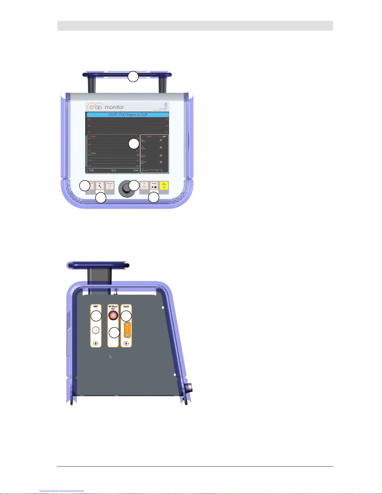
3.2.1 CNAP™ Monitor 500
Illustration 1: Front view
Carrying handle
Display
Battery LED
Click-wheel control
Power LED
Control panel
Illustration 2: Patient connectors
CNAP™ cable port
BP Wave Out: analog output
port
NBP cuff connector
1
3 5
6
1 3
2
4
2
Page 12
Introduction
CNAP™ Monitor 500 Page 3-3 Version 3.5.1, PN: 21-FHZU-10002
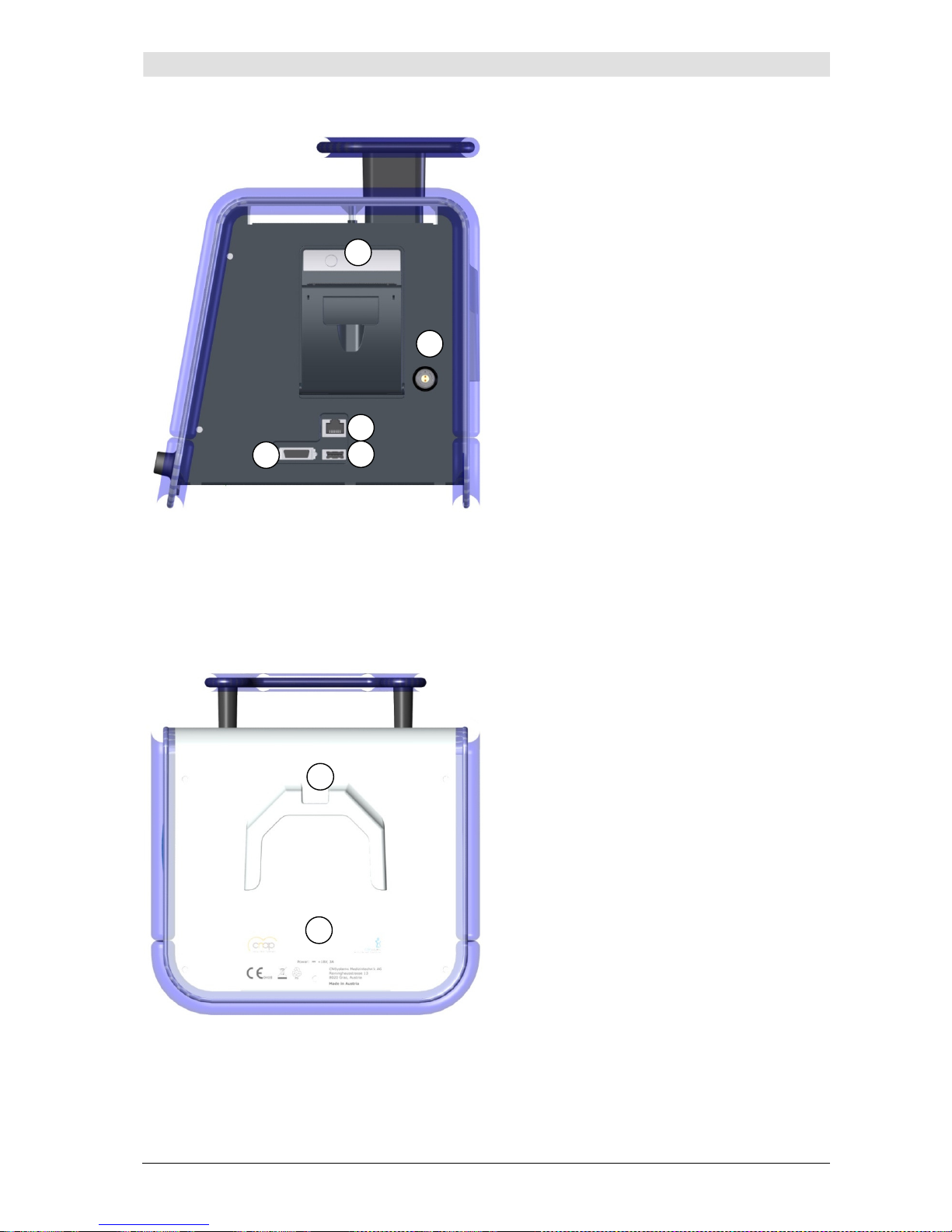
Illustration 3: Printer, interface, power supply
Thermal printer
Mains power port
USB connector: software
updates
Ethernet connector
AUX: analog output port
(only functioning with the
CNAP™ Monitor 500at)
Illustration 4: Back view
Holding device channel (optional)
Type plate
1
3
2
4
1
2
5
Page 13
Introduction
CNAP™ Monitor 500 Page 3-4 Version 3.5.1, PN: 21-FHZU-10002
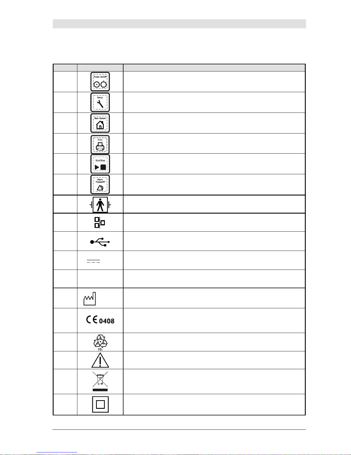
CNAP™ Monitor 500 symbols
The following table describes all symbols in use on the CNAP™ Monitor 500 and its components:
No. Symbol Description
1
•
Power On/Off
(monitor on/off)
2
•
Setup
(monitor, measurement, service settings)
3
•
Main Screen
(return to main screen)
4
•
Print
5
•
Start/Stop
(of a measurement)
6
•
Alarm Pause/Off
7
• Input port of type BF is protected from defibrillation pulses
8
• Ethernet connector
9
• USB connector
10
+18V
• 18 V DC supply required
11 AUX • Analog output port
12
2007 01
• Production date
13
Device meets the European standard for medical devices 93/42/EWG,
Appandix IX in the changed version 2007/47/EG, annex IX as amended by 2007/47/EC
14
• Recycle damaged sealed lead gel battery
15
• Caution: see accompanying documents
16
• Separate disposal of electric and electronic appliances
17
• Protection class II
Page 14
Introduction
CNAP™ Monitor 500 Page 3-5 Version 3.5.1, PN: 21-FHZU-10002
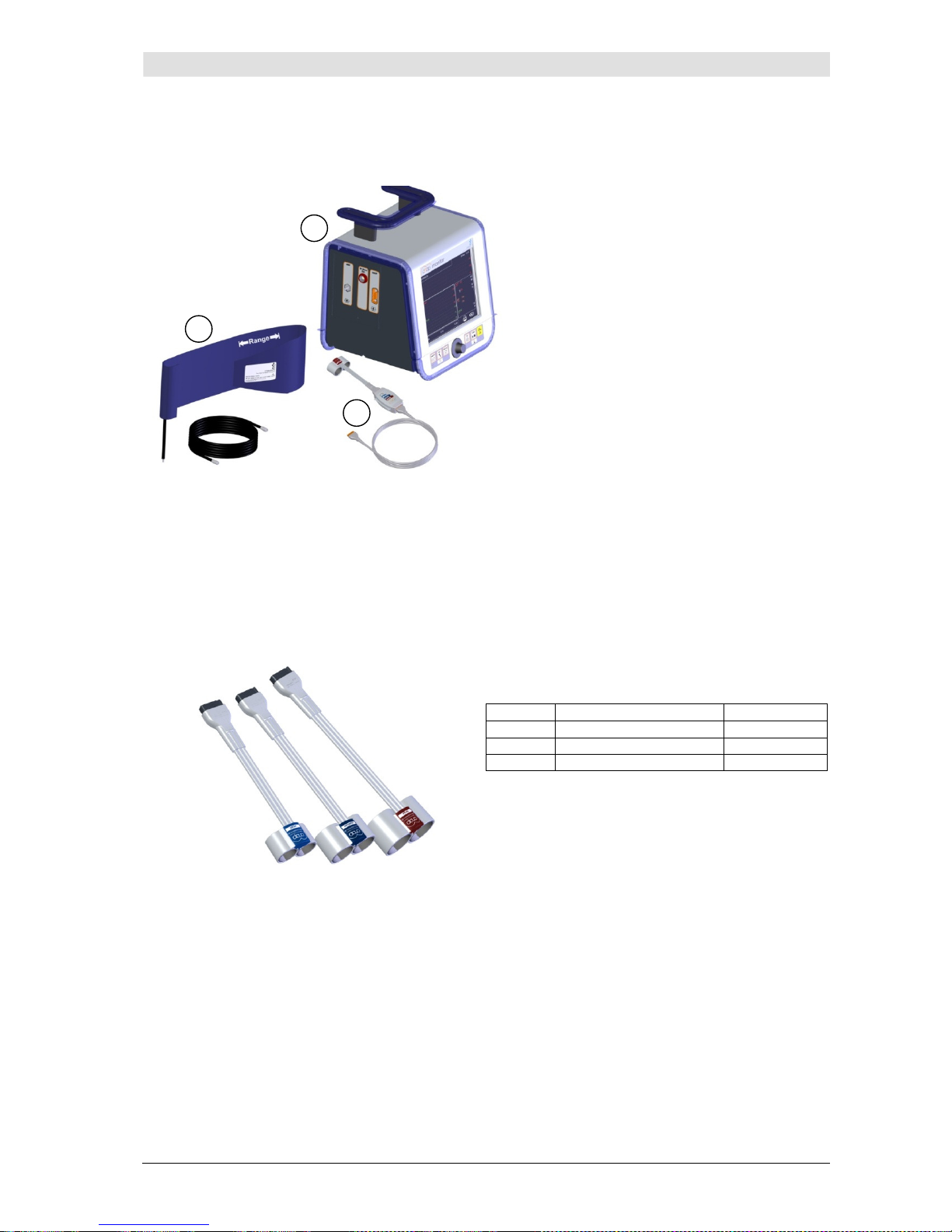
3.2.2 CNAP™ hardware
Illustration 5: CNAP™ Monitor 500
CNAP™ Monitor 500
CNAP™ hardware
NBP hardware
3.2.2.1 CNAP™ double finger cuff
The CNAP™ double finger cuff comes in three sizes, each size being marked by a different colored
hood.
Illustration 6: CNAP™ finger cuffs
Size Diameter (mm) Color
L 24 - 28 Dark red
M 18 - 24 Dark blue
S 10 - 18 Light blue
1
3
2
Page 15
Introduction
CNAP™ Monitor 500 Page 3-6 Version 3.5.1, PN: 21-FHZU-10002
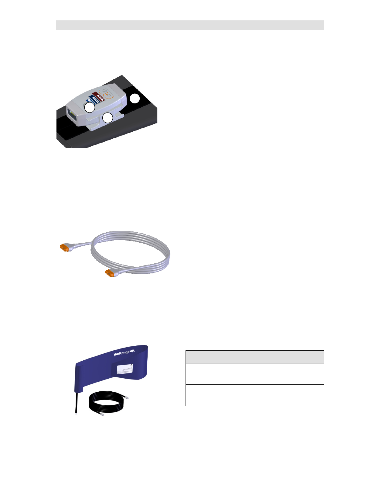
3.2.2.2 CNAP™ controller
Illustration 7: CNAP™ controller
3.2.2.3 CNAP™ cable
Illustration 8: CNAP™ cable
3.2.3 NBP cuff
The NBP cuff is intended for oscillometric blood pressure measurement and is available in four sizes:
Illustration 9: NBP cuff
Size
Arm circumference
(cm)
Child 12 - 19
Small Adult 17 - 25
Adult 23 - 33
Large Adult 31 - 40
The CNAP™ controller connects the CNAP™ double
finger cuff and the monitor via the CNAP™ cable.
The jacks for the CNAP™ double finger cuff and the
CNAP™ cable are adequately designed so as to avoid
any confusion when putting the cables into the corresponding jacks.
•
The graphics on the upside of the CNAP™
controller help choosing the right size of CNAP™
double finger cuff.
•
The CNAP™ controller is fastened to the
patient's forearm by means of the CNAP™ forearm fixing cuff with a Velcro fastener.
•
The fixture for CNAP™ controller connects
the CNAP™ forearm fixing cuff mechanically to
the CNAP™ controller. The fixture for CNAP™
controller needs to be setup-up centrally (see
also illustration 18).
The CNAP™ cable connects the monitor and the
CNAP™ controller.
1
2
3
Page 16
Introduction
CNAP™ Monitor 500 Page 3-7 Version 3.5.1, PN: 21-FHZU-10002
3.3 Power supply
The CNAP™ Monitor 500 is supplied with power by means of either mains operation via an external
power adapter or by an integrated sealed lead gel battery. In case of power supply interruptions or
even power outage, the monitor will automatically switch to battery operation.
CAUTION:
• Carefully read and keep in mind the precautions regarding power supply.
3.3.1 Mains operation
During mains operation, the CNAP™ Monitor 500 is connected to a power adapter suited for a supply
voltage of 100-240 VAC (± 10%) and a mains frequency of 50/60 Hz (see Appendix C – Technical
specifications). When the CNAP™ Monitor 500 is connected to the mains power supply, the integrated
sealed lead gel battery is recharged as well. There is no time limit on the monitor being on mains operation.
The CNAP™ Monitor 500 can be connected to a supply network system according to CISPR 11.
NOTE:
• The battery recharge symbol on the battery status of the TFT-display shows
when the integrated battery is being recharged.
• The battery status indicates the present battery charge status when the monitor is
running on battery (without mains power supply).
CAUTION:
• Do not use any power supply accessories, but those intended and authorized by
CNSystems Medizintechnik AG for utilization with the monitor!
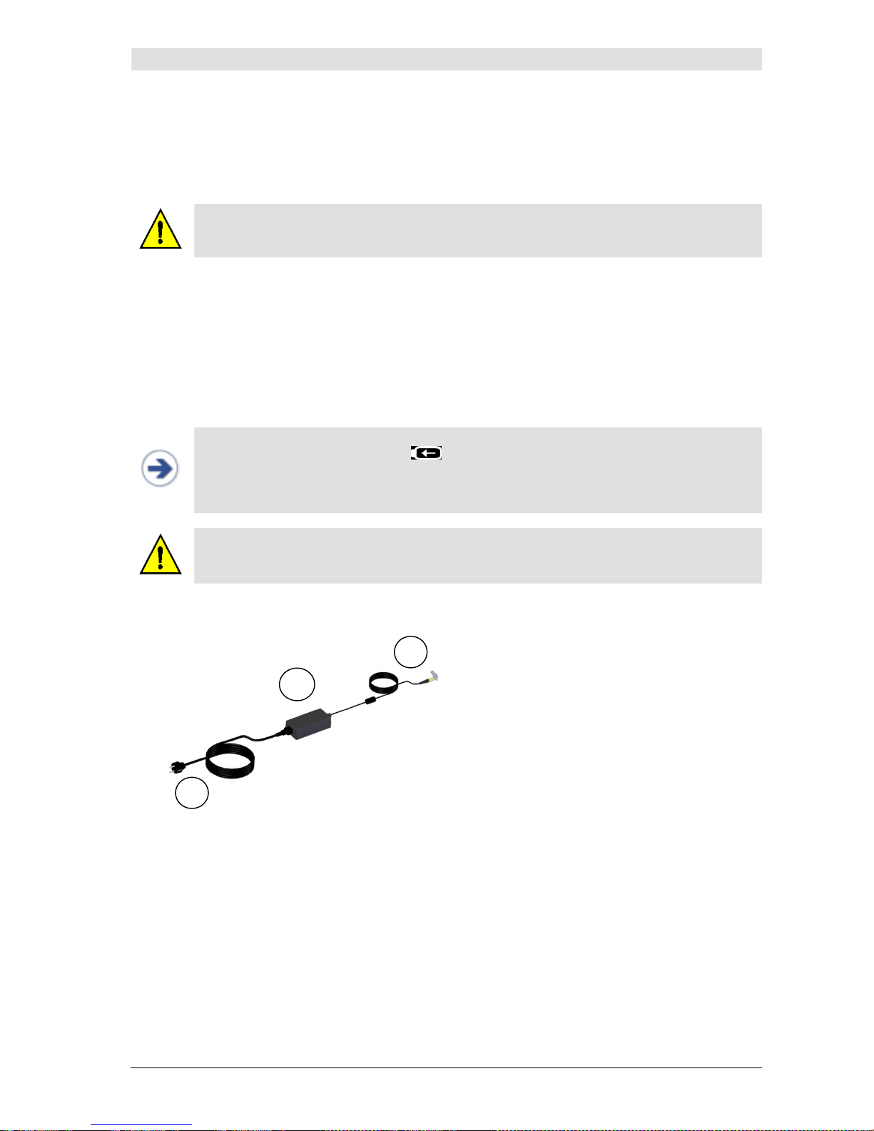
Illustration 10: Power cord
Power cord
Power adapter
Cable connecting power adapter
and monitor
3.3.2 Battery operation
The integrated sealed lead gel battery enables the CNAP™ Monitor 500 to operate on battery for up to
120 minutes, depending on the CNAP™ calibration intervals, printer use and brightness of display.
When the CNAP™ Monitor 500 is connected to the mains power supply, the integrated sealed lead gel
battery is recharged as well. If the monitor runs on battery, the battery charge status will be indicated
on the TFT-display in 25% steps. The battery charge status is also indicated via the battery LED on
the front side of the monitor.
2
3
1
Page 17
Introduction
CNAP™ Monitor 500 Page 3-8 Version 3.5.1, PN: 21-FHZU-10002
LED color Battery charge status
Green Device runs on battery, battery charge status 100 – 25%
Orange Device runs on battery, battery charge status ≤ 25%
Red Device runs on battery, automatic shutdown within 15 minutes
In addition, a low battery charge status (5 minutes of remaining operation time on battery) is indicated by the status message
MU: Battery Low
, a depleted battery by
MU: Battery Depleted
on the TFT-display (see battery status below). For security reasons, the measurement is stopped with
a depleted battery and the monitor is shut down automatically.
STOP:
• Damaged or time-worn batteries might considerably reduce the maximal operating
time on battery. The accuracy of the device's battery charge status is only guaranteed when using undamaged batteries and under normal operation conditions.
CAUTION:
• Total discharge may damage the battery. Therefore charge the battery at every op-
portunity.
• Immediately charge the battery with a battery charge status ≤ 25%, or as soon as
possible and for at least 5 hours at ≤ 50%.
• Extreme temperatures might impair your battery performance. For optimal operabil-
ity, charge and use the battery at temperatures < 35°C (95°F).
• In the case of infrequent use, charge the battery at least every 3 weeks for at least 5
hours.
• In order to guarantee a long product lifetime, preferably use the CNAP™ Monitor 500
in mains operation.
• When disposing of used batteries, adhere to your local waste disposal regulations.
• Do not use any batteries but those authorized by CNSystems. Use of non-authorized
batteries might damage the monitor.
• Before turning on the appliance for the first time, be sure to charge the integrated
sealed lead gel battery for 4.5 hours.
• In order to guarantee safe operability of the CNAP™ Monitor 500, the battery has to
be replaced after 24 months in the course of maintenance service.
NOTE:
• When switching from mains operation to battery operation, it can take up to a minute
until the battery charge status is displayed.
• The thermal printer cannot be operated when the battery charge status is ≤ 25%.
• During display of a status message or alarm, the battery symbol will be faded out –
however, a critical battery status can be seen through the LED color being orange or
red.
Page 18
Introduction
CNAP™ Monitor 500 Page 3-9 Version 3.5.1, PN: 21-FHZU-10002
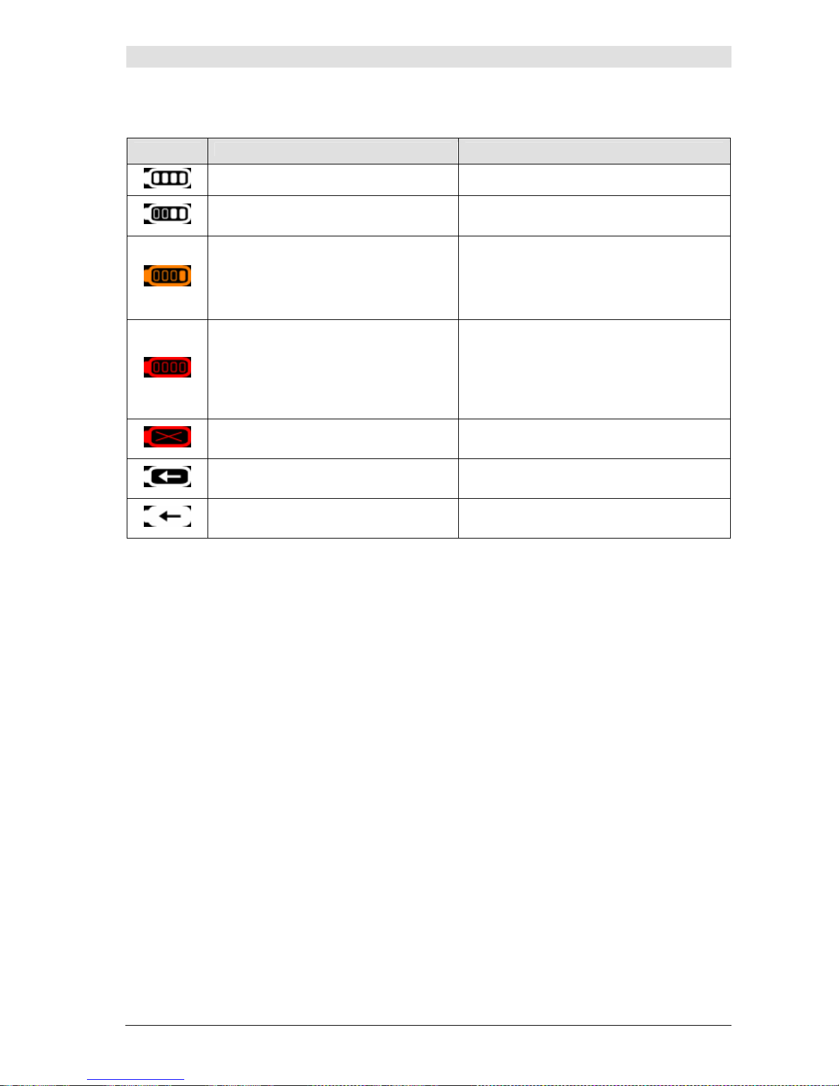
Battery status
Symbol Battery charge status Resulting measure
• Battery charge status 100%
• Battery charge status 50%
• Switch to mains operation via power
adapter as soon as possible
• Very low battery charge status (<
25%), battery operation still possible
• Immediately switch to mains operation
via power adapter
• Printing deactivated
• Current print job cancelled
• Technical alarm
MU: Battery Low
• Battery depleted, operation possible
for 5 minutes at most; monitor is
switched off
• Immediately switch to mains operation
via power adapter
• Technical alarm
MU: Battery De-
pleted
• Current measurement discontinued,
monitor switched off automatically
• Battery malfunction, acoustic techni-
cal alarm signal
• Call a service technician (CNSystems)
• Battery is being charged while run-
ning on mains power
• Fully charged while running on
mains power
Page 19
Introduction
CNAP™ Monitor 500 Page 3-10 Version 3.5.1, PN: 21-FHZU-10002
3.4 First steps
3.4.1 Power On/Off
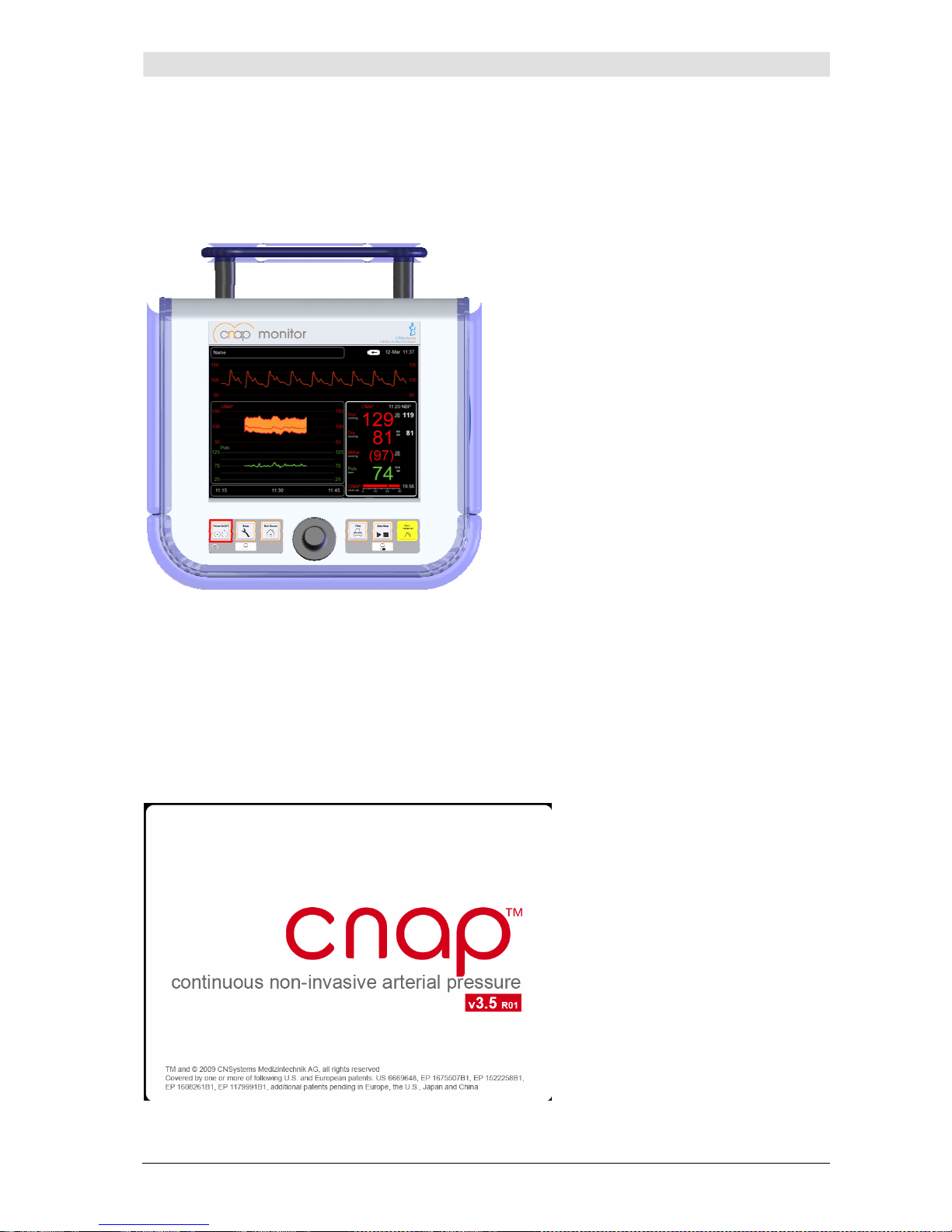
The
Power On/Off
key is located in the left lower corner on the front side of the device.
Illustration 11: Front view
Switching on the monitor
The CNAP™ Monitor 500 is switched on by pressing the
Power On/Off
key located on the front side
of the device for two seconds. While the CNAP™ Monitor 500 is booting up, device and software information is displayed on the splash screen. The green power LED indicates the operation status of the
device. The operating system of the monitor initializes and performs a system self-test, then the main
screen is displayed.
In addition, the monitor also performs an automatic function test of its alarm system during startingup time (see chapter 6 – Alarm system).
Illustration 12: Splash screen
Page 20
Introduction
CNAP™ Monitor 500 Page 3-11 Version 3.5.1, PN: 21-FHZU-10002
Switching off the monitor
The CNAP™ Monitor 500 is switched off by pressing the
Power On/Off
key located on the front side
of the device for 2 seconds.
CAUTION:
• The
Power On/Off
key does not interrupt the monitor's power supply. In order to
interrupt power supply, the operator needs to disconnect the power cord.
3.4.2 Access/return to main screen
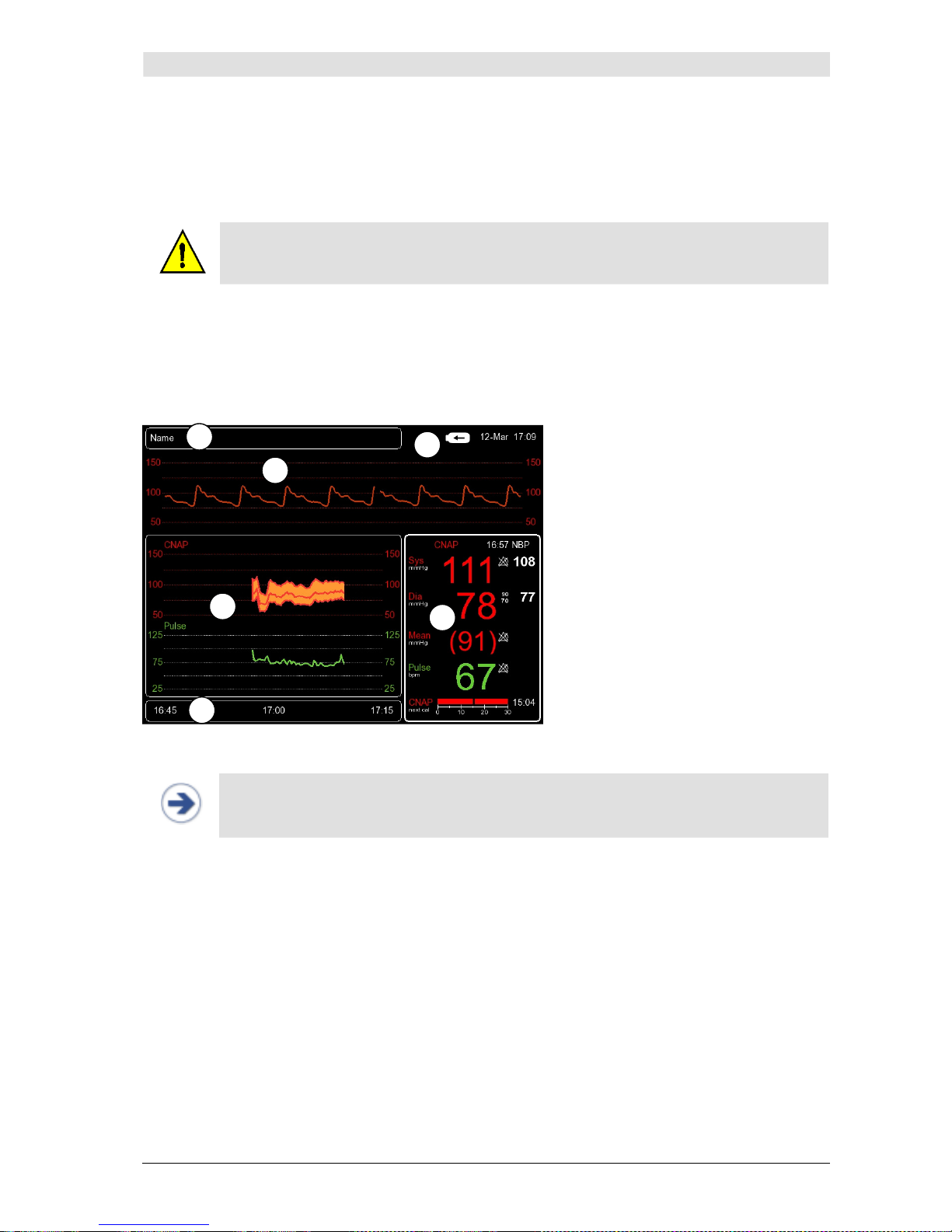
After having started the monitor, the main screen appears which displays all measuring parameters
and signals and enables the operator to access all menus.
Arrangement of the screen:
Alarm frame
CNAP™ Signal view
Trend frame
Parameter frame
Navigation frame
Battery charge and
printer status
Illustration 13: Main screen
NOTE:
• In order to return to the main screen from any submenu, just press the
Main
Screen
key on the front of the monitor.
1
3
2
4
5
6
Page 21
Introduction
CNAP™ Monitor 500 Page 3-12 Version 3.5.1, PN: 21-FHZU-10002
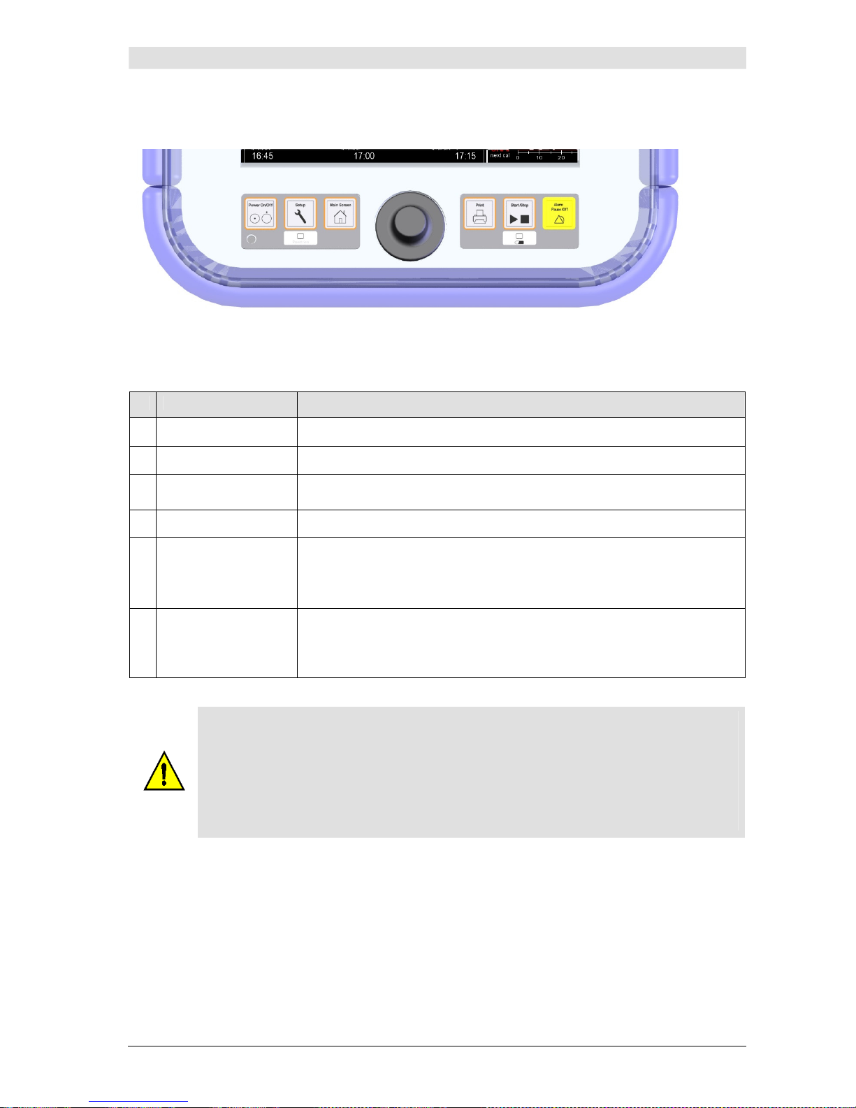
3.4.3 Fast access keys
Illustration 14: Fast access keys
Membrane keys on the front side of the CNAP™ Monitor 500 enable fast access to important functions:
Key Function
1
Power On/Off
Switching on/off the monitor
2
Setup
Access to configuration menu
3
Main Screen
Return to main screen from any submenu
4
Print
Start/stop printing
5
Start/Stop
Start: Manual display of the
Setup Patient
dialog to continue measurement (see chapter 5.1 – Patient entry) if this is not displayed automatically.
Stop: Stop measurement (CNAP or NBP).
6
Alarm Pause/Off
Alarm functions control:
Press Alarm Pause/Off key once: set alarm reminder
Press Alarm Pause/Off key twice: set alarm pause
Press Alarm Pause/Off key three times: re-activate alarm function
CAUTION:
• The
Start/Stop
key controls stop of CNAP™ measurements. In case of an active
NBP measurement, the operator first stops the NBP measurement by pressing the
Start/Stop
key once. Only pressing the
Start/Stop
key for a second time will
stop the active CNAP™ measurement.
• The start function of the
Start/Stop
key is limited to display the
Setup Patient
dialog for continuing the measurement. When applying the finger cuff, the patient setup dialog is displayed automatically.
Page 22
Introduction
CNAP™ Monitor 500 Page 3-13 Version 3.5.1, PN: 21-FHZU-10002
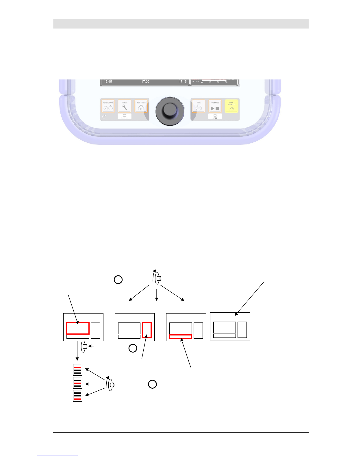
3.4.4 Menu navigation – click-wheel control
The monitor's click-wheel control enables the operator to select menus and settings and to access
certain functions. Wheeling the control enables the operator to navigate through menus, while pressing on the control ("clicking") confirms the menu choice.
Illustration 15: Click-wheel control
Selection and confirmation of functions/menu items:
1. Select the desired function/menu item by wheeling the control (green bar).
2. Pressing the click-wheel control then confirms the selection. Subsequently, either a drop-down list
appears or the function is activated automatically (e.g. from
on
to
off
).
3. Wheeling the click-wheel control – drop-down list appears.
3.4.5 Menu selection
Menus can be accessed in 2 ways:
• Frequently used functions can be selected by the monitor's fast access keys (see chapter 3.4.3 –
Fast access keys).
• Or, menus and their functions can be selected by means of the click-wheel control (see chapter
3.4.4 – Menu navigation – click-wheel control).
Illustration 16: Menu selection
Wheel
Click
Wheel
1
2
3
Trend
frame
A
larm frame
Navigation
f
rame
Parameter
frame
Page 23
Introduction
CNAP™ Monitor 500 Page 3-14 Version 3.5.1, PN: 21-FHZU-10002
3.5 Patient setup
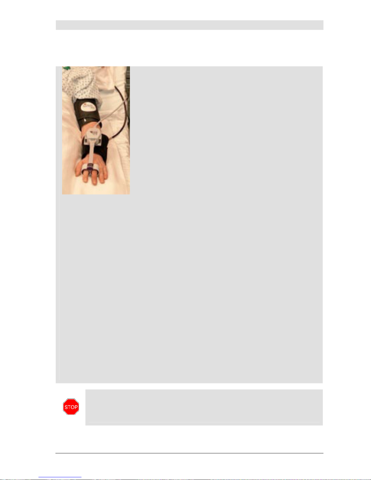
STOPP:
• Please be aware that CNAP™ finger cuffs as well as CNAP™ Cuff Controller needs to
be setup without tension. The fixation of CNAP™ Cuff Controller is to be setup centrally (see illustration below). This obviates tension during a measurement due to dislocation of the patient which can disturb the CNAP™ measurement significantly.
1. Starting up the CNAP™ Monitor 500:
Press
Power On/Off
and confirm the alarm self-test (test
alarm signal) by pressing
Alarm Pause/Off.
2. Patient setup:
a) Choose the correct CNAP™ double finger cuff size by means
of the graphic on the CNAP™ controller. If a patient's finger
size is between two cuff sizes, choose the larger cuff.
b) Assemble the CNAP™ hardware by connecting the CNAP™
double finger cuff, the CNAP™ controller, the CNAP™ cable
with the CNAP™ Monitor 500. All plugs and connectors are
designed so as to make it impossible to switch them accidentally.
c) Equip the patient with the CNAP™ hardware: The CNAP™
double finger cuff is placed on the proximal joints of the index and middle fingers. Ensure that the cuff cables run along
the outside of the patient's arm.
d) Fasten the CNAP™ controller to the patient's forearm by
means of the fixing cuff (with a Velcro fastener) and make
sure that the hand with the CNAP™ double finger cuff is
placed at heart level (see illustration on the side).
3. Putting on the NBP cuff:
a) Make sure that only NBP cuffs authorized by CNSystems are used and that you apply the
correct size to the patient (Child, Small Adult, Adult, Large Adult).
b) Place the blood pressure cuff on the patient's upper arm, preferably contralaterally, at
heart level. The marker on the NBP cuff should be directly above the brachial artery.
c) Connect the NBP cuff with the NBP air connector on the patient side of the CNAP™ Moni-
tor 500.
4. Starting the measurement:
d) New entry of patients:
Selecting the functions
New Patient - Adult Defaults
or
New Patient - Pediat-
ric Defaults
starts a new measurement automatically – previous measurements will be
deleted. Detailed patient data input can be performed at a later time via the
Alarm
frame
in the
Patient Data
menu.
e) Use current patient data:
When selecting the option
Use Current Patient Data
, all patient data is maintained.
To continue a measurement, press the
Start/Stop
key as the
Setup Patient
dialog
is not displayed automatically. After selection of the option
Use Current Patient Da-
ta
, the measuring process starts automatically.
Illustration 17:
Patient-Setup
Page 24
Introduction
CNAP™ Monitor 500 Page 3-15 Version 3.5.1, PN: 21-FHZU-10002
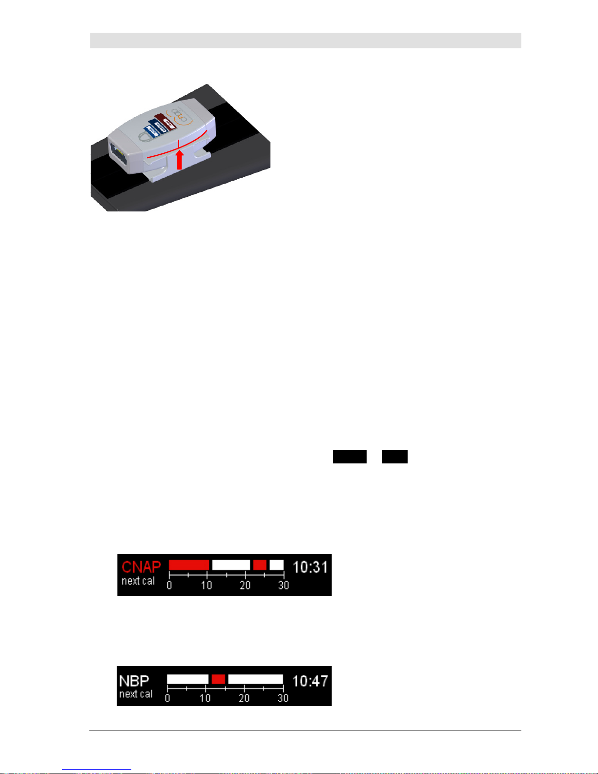
Illustration 18: CNAP™- Controller-Fixation
3.6 Timer
The timer displays the CNAP™ change of finger and/or NBP measurements following within the
next 30 minutes (calibration measurements), thus making the following measurement-related
interruptions of continuous blood pressure perceptible and allowing adequate time management
(see below).
All next calibration measurements within 30 minutes will be graphically displayed and are color coded (continuous bar graph display).
• Red = long interruption of measurement: CNAP™ change of finger (+ NBP measurement).
The red bar always refers to a completely new calibration of CNAP™ change of finger
(+NBP measurement) resulting in a longer interruption of continuous blood pressure of
approx. 90 seconds.
• White = short interruption of measurement: NBP measurement
The white bar always refers to an independent NBP measurement of shorter duration of
approx. 45 seconds.
The immediate next calibration is displayed with
CNAP
or
NBP
to the left next to the bar
graph display and numerically as a countdown (mm:ss) to the right of the bar graph display.
Example 1:
The immediate next interruption is a CNAP™ change of finger (+ NBP measurement) in 10:31
minutes, followed by another NBP measurement in approx. 21 minutes, a CNAP™ change of finger (+ NBP measurement) in 25 minutes and another NBP measurement in more than 30 minutes.
Example 2:
The immediate next interruption is an NBP measurement in 10:47 minutes, followed by another
CNAP™ change of finger (+ NBP measurement) in approx. 15 minutes and another NBP measurement in more than 30 minutes.
Page 25

Introduction
CNAP™ Monitor 500 Page 3-16 Version 3.5.1, PN: 21-FHZU-10002
NOTE:
• The timer is only displayed during active measurement (with available CNAP values)
at the bottom of the
Parameter frame
.
• A manual
NBP: Start
resets the NBP timer: this means a reset of the NBP count-
down to
NBP: Cal Interval
set in the
Parameter
menu.
• A manual
CNAP: Change Finger
resets the CNAP timer. In addition, also a reset
for the NBP is carried out as soon as the NBP is triggered by CNAP. This means a reset of both the CNAP and the NBP countdown to the
CNAP: Cal Interval
and
NBP: Cal Interval
set.
TIME MANAGEMENT:
Example: As next calibration a CNAP™ change of finger (+ NBP measurement) will be in
5:00 minutes; however, continuous blood pressure will probably be essential at this
time.
• Option 1: Delay interruption
The user delays the next calibration by increasing the
CNAP: Cal Interval
in the
Parameter
menu to max. 60 minutes. This option does not apply if the
CNAP: Cal
Interval
has already been set to 60 minutes.
• Option 2: Anticipate interruption
The user immediately starts a manual
CNAP: Change Finger
in the
Parameter
menu. This CNAP Change Finger resets both timers at the time of triggering CNAP or
NBP. With
CNAP: Cal Interval
of 30 minutes, the subsequent interruption would
only be in 30 minutes, provided the
NBP: Interval
has not been set with a shorter
interval.
Option 1 and option 2 apply analogously to the NBP if this is planned as the next calibration.
3.7 Perfusion Index
The Perfusion Index (PI) describes the signal quality of perfusion in the finger artery in the
CNAP™ cuff on a scale from 0 (no signal) to 6 (very good signal). The currently found PI is
shown on the screen as a white bar. The maximum value that was found during the calibration
phase is marked with a green rectangle in the bar graph (see example 1). Patients with a very
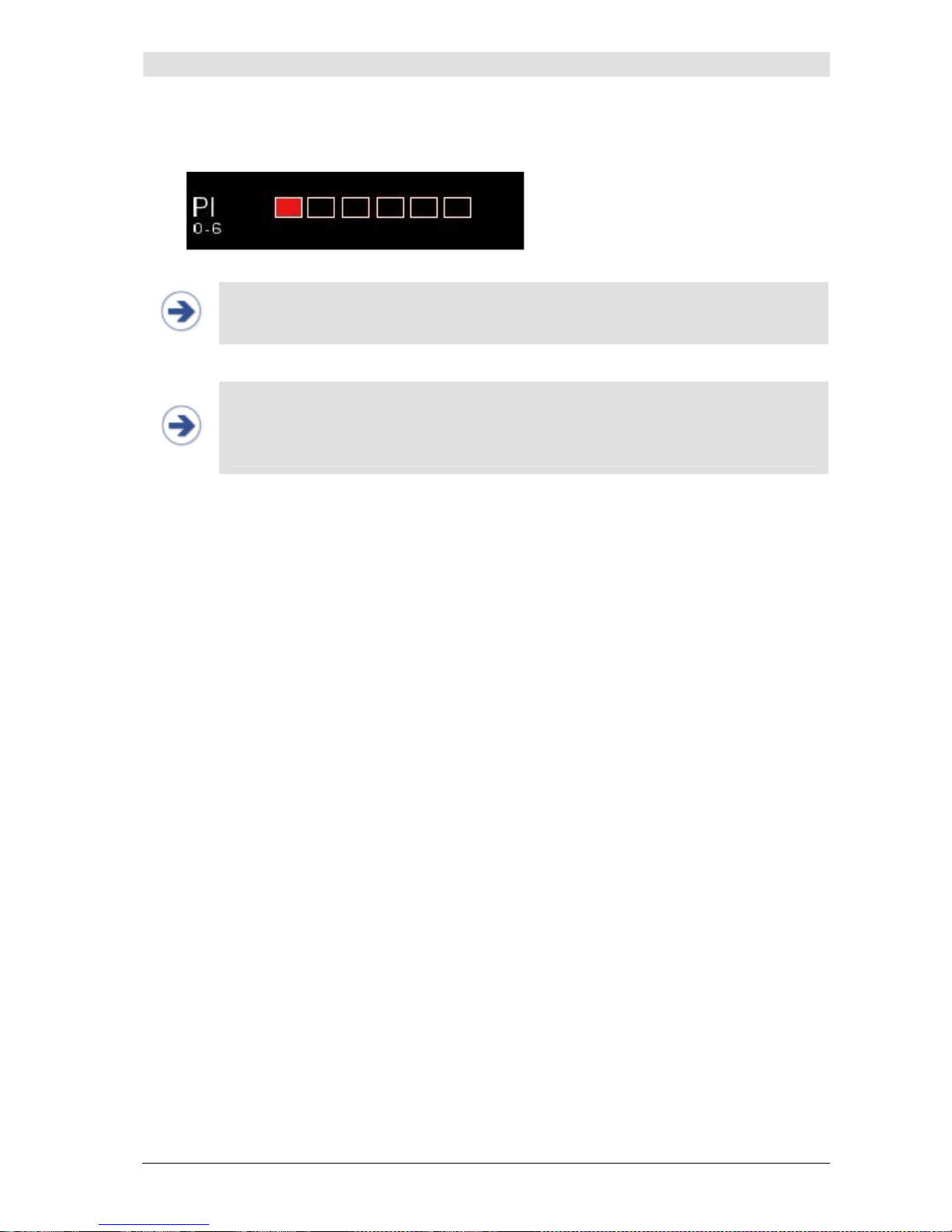
bad peripheral blood circulation can be identified by means of a very low PI ≤ 1. Also a red rectangle at the very left position in the bar graph is displayed (see example 2). Such a case involves the risk of a CNAP™ interruption due to insufficient peripheral circulation, i.e., in the
course of measurement it could fail temporarily or completely. The red rectangle will disappear
if a PI > 1 will be found.
During measurement, a temporary, too low signal quality will be displayed with the technical er-
ror message
CNAP: Artefact
.
If the signal quality is insufficient for more than 10 seconds,
particularly during the initialization phase, the technical error message
CNAP: Check Cuff –
Low Light Signal
will be displayed. A further NBP measurement by means of the CNAP™
Monitor 500 remains unaffected by this.
Example 1: current PI = 3, maximum found = 5 – good signal quality
Page 26
Introduction
CNAP™ Monitor 500 Page 3-17 Version 3.5.1, PN: 21-FHZU-10002
Example 2: current PI ≤ 1 - bad signal quality
NOTE:
• The Perfusion Index will only be displayed during the initialization phase (until NBP
measurement -
NBP: triggered by CNAP
).
NOTE:
• The reason for a low light signal may be
• insufficient peripheral circulation
• or a misplaced CNAP™ finger cuff.
Before starting a new measurement the position of the finger cuff must be checked.
Page 27
Monitor configuration
CNAP™ Monitor 500 Page 4-1 Version 3.5.1, PN: 21-FHZU-10002
4 Monitor configuration
Monitor settings ....................................................................................................................4-1
Measurement settings............................................................................................................4-1
Service settings ....................................................................................................................4-2
BP Wave Out (patient monitors)..............................................................................................4-2
Interfaces (optional) ..............................................................................................................4-6
4.1 Monitor settings
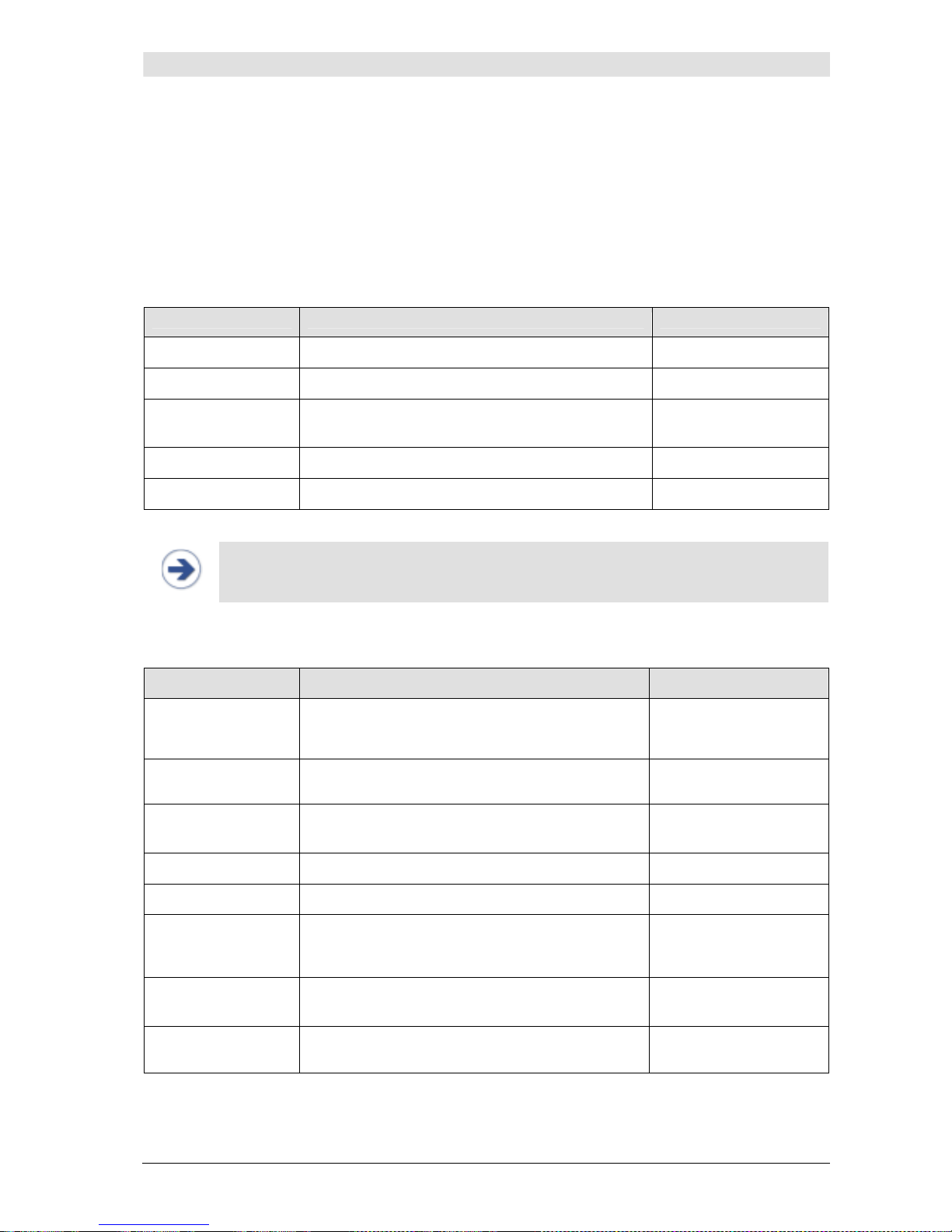
Menu item Description Settings
Brightness
Regulates the brightness of the TFT-display
20(20)100, Auto
Language
Language setting for the user interface
EN, DE, FR, ES, IT
Date
Date setting
YYYY/MMM/DD
e.g. 1970/MAR/10
Time
Time setting
hh:mm:ss
Record
Sets data recording on the USB
Off, User, Debug
NOTE:
• Monitor settings are saved automatically. Loss of settings only occurs in the case of
interruption of power supply (no mains operation, followed by battery depletion).
4.2 Measurement settings
Menu item Description Settings
NBP: Mode
Automatic or manual NBP measurement at a variance of > 25mmHg compared with the last NBP
for at least 45 seconds.
Auto, Manual
NBP: Interval
Setting of time interval [min] for automatic NBP
measurements
Off, 5(5)30, 45, 60
CNAP:
Cal Interval
Setting of intervals [min] for automatic change of
signal source in the CNAP™ double finger cuff
5(5)60 min
Audio Trend…
Setting of source and volume of audio trend Submenu
Display…
Setting of trend view: Display and scaling Submenu
Print Options…
Setting of print options: Delay time for snapshot
prints, activation of
Print on Alarm
(see chap-
ter 8.4 Print Options)
Submenu
Parameter
Averaging
Averaging of displayed numeric parameters [sec]
Off, 5, 10, 15 beats
Patient Category
Presetting of patient category as a focus in the
Setup Patient
dialog
Adult, Pediatric
Page 28
Monitor configuration
CNAP™ Monitor 500 Page 4-2 Version 3.5.1, PN: 21-FHZU-10002
NOTE:
• Measurement settings are saved automatically for any current or future measure-
ment.
• Loss of power supply (interruption of mains operation, followed by depletion of bat-
tery) entails the loss of measurement settings.
• All settings can be changed to factory settings in the
Service
menu (see chapter 4.3
– Service settings.
4.3 Service settings
NOTE:
• The
Service
menu is divided into 2 layers which can be accessed by entering a
password.
• You will find the password for the user menu in the CNAP™ Monitor 500 "Service
manual for users".
• You will find the password for the service menu in the CNAP™ Monitor 500 "Instruc-
tions for service" (service manual).
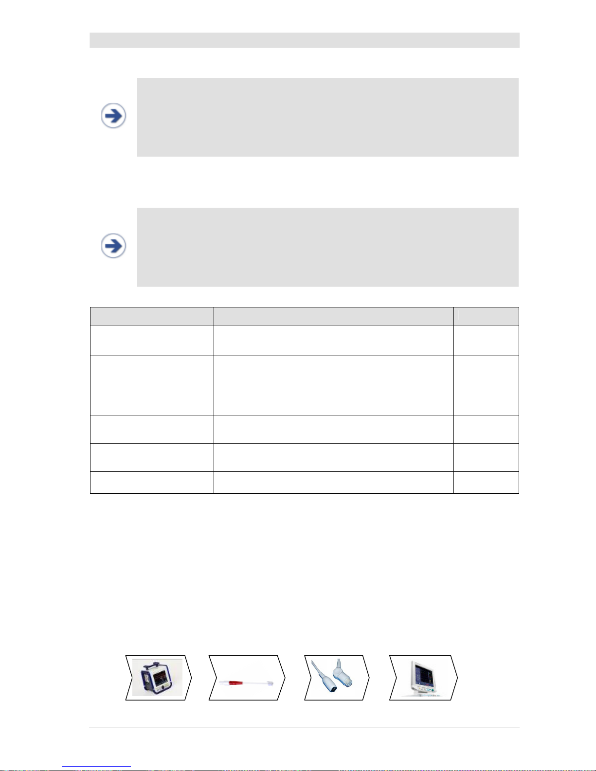
Menu item Description Settings
Restore Factory Settings
Restore factory settings
Yes, No
Alarm Defaults…
Enables to adjust alarm limits, reminder, pause and
volume for the patient categories (
Adult, Pediatric
)
within the limits of factory settings. The alterations will
be used for each new measurement. The operator/user
can also restore factory settings.
Submenu
Log…
Lists technical alarms by means of languageindependent error codes
Submenu
Function Tests …
Function tests of the modules IBP analog output, printer and CNAP/NBP
Submenu
Advanced…
Menu for software update Submenu
4.4 BP Wave Out (patient monitors)
4.4.1 BP Wave Out configuration
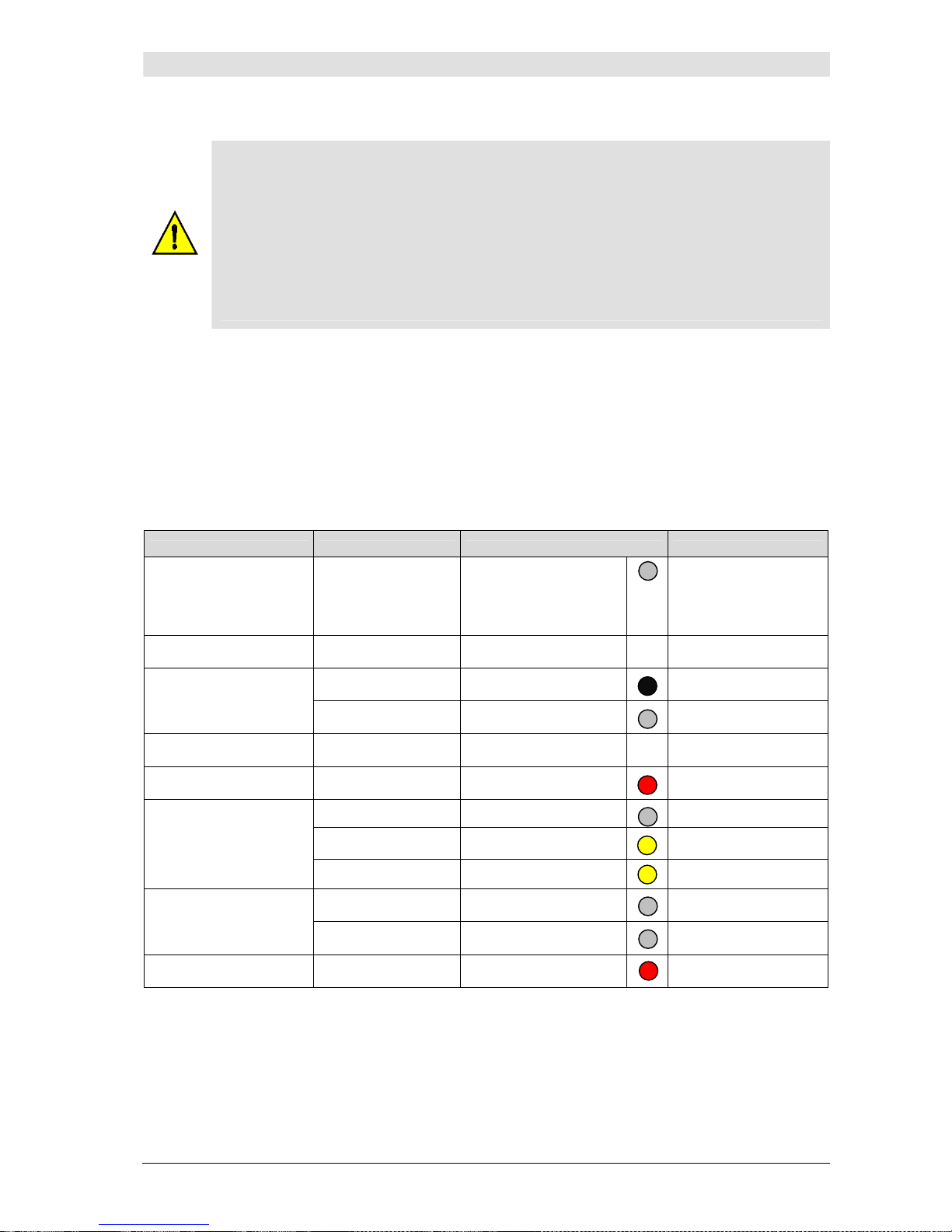
Similar to the BP waveform obtained from an invasive catheter (e.g. radial artery), the CNAP registered blood pressure waveform can be interfaced to patient monitors by means of the "BP Wave Out"
output port located on the left side of the CNAP™ Monitor 500 (see chapter 3.2.1, illustration 2). As
can be seen from the graphics below, the CNAP™ Monitor 500 can also be connected with the patient
monitor by a) CNAP™ Transducer Cable and b) IBP Interface Cable (see also chapter 15.2 - Connections).
CNAP™ Monitor 500 Transducer Cable Interface Cable Patient Monitor
Page 29
Monitor configuration
CNAP™ Monitor 500 Page 4-3 Version 3.5.1, PN: 21-FHZU-10002
CAUTION:
• In order to connect the CNAP™ Monitor 500 to another patient monitor with invasive
BP port, the following 2 compatible cables are needed (see compatibility list below):
• CNAP™ Transducer Cable: suitable for the different patient monitors and available in 4
colors (grey, blue, red, yellow). The cable is connected to the CNAP™ Monitor 500 (patient side) and enables access to the CNAP™ blood pressure waveform using an RJ11
6P4C connector. The compatible CNAP™ Transducer Cable is a component for the
CNAP™ Monitor 500 and is only available from CNSystems Medizintechnik AG.
• IBP Interface Cable: connects the IBP port of a patient monitor to the RJ11 6P4C con-
nector of the CNAP™ Transducer Cable. Selected IBP Interface Cables (e.g. Abbott IBP
catheter) are also available from CNSystems Medizintechnik AG.
Unlike the analog output port (see chapter 4.5 - Interfaces), the CNAP™ blood pressure waveform
signal via the "BP Wave Out" is standardized. Its sensitivity always amounts to 5 µV/V/mmHg. The
bridge voltage on the CNAP™ Monitor 500 depends on the supply voltage the patient monitor provides.
If, for example, the supply voltage is 4 V, the sensitivity will be calculated as follows: 5 µV/V/mmHg x
4 V = 20 µV/mmHg
4.4.2 Compatibility list
Make Type Transducer Cable Interface Cable
Siemens
SC 9000XL,
SC 9000,
SC 8000,
SC 7000
20-FFKA-01200
20-HHKA-01201
Dräger SC 7000 n/a
20-HHKA-01202
Marquette 20-FFKA-01201
20-HHKA-01214
GE
Marquette
Solar8000M
20-FFKA-01200
20-HHKA-01214
Spacelabs n/a n/a
20-HHKA-01215
Mindray Beneview T5 20-FFKA-01202
20-HHKA-01216
Intellivue M8008A 20-FFKA-01200
20-HHKA-01218
Intellivue MP50 20-FFKA-01203
20-HHKA-01218
Philips
Intellivue MP70 20-FFKA-01203
20-HHKA-01218
AS/3 20-FFKA-01200
20-HHKA-01230
Datex
S/5 20-FFKA-01200
20-HHKA-01230
HP Viridia 20-FFKA-01202
HP/Abbot
Page 30
Monitor configuration
CNAP™ Monitor 500 Page 4-4 Version 3.5.1, PN: 21-FHZU-10002
4.4.3 Zeroing
After having connected the CNAP™ Monitor 500 and the patient monitor using a) the CNAP™ transducer cable and b) the IBP interface cable (see 4.4.1 - BP Wave Out configuration), zeroing must be
performed:
a) Zeroing without active measurement:
Before and after an active measurement (without displayed CNAP values), zeroing is activated
automatically (a zero signal is output). Zeroing can be immediately performed on the patient monitor.
b) Zeroing during active measurement:
During an active measurement (with displayed CNAP values), zeroing is inactive; however, it
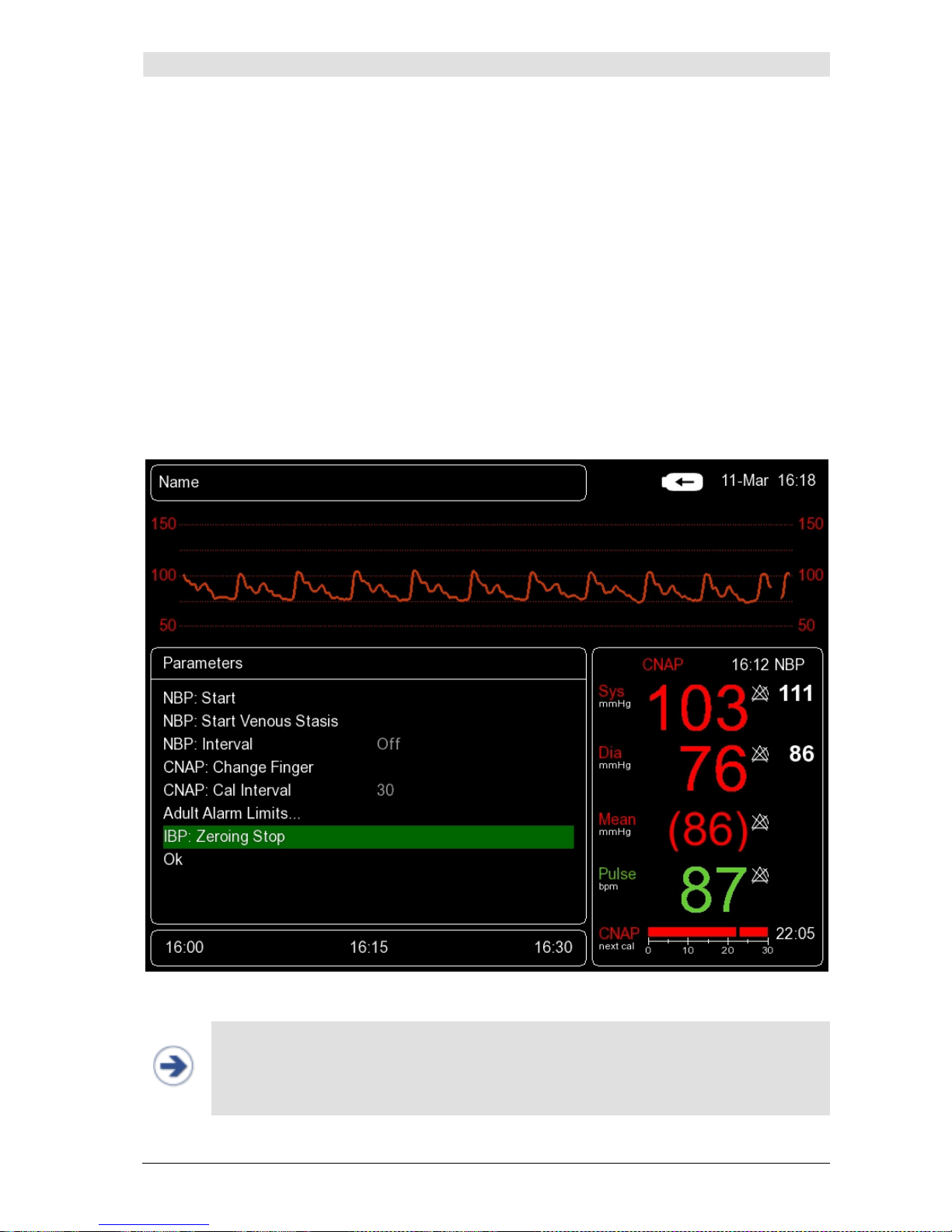
can be activated manually in the
Parameter
menu:
1. CNAP™ Monitor 500: Activate zeroing via
IBP: Zeroing Start
2. Patient monitor: Performing the zeroing process
3. CNAP™ Monitor 500: Deactivate zeroing via
IBP: Zeroing Stop
Illustration 19: Parameter menu: IBP: Zeroing
NOTE:
• Usually a patient monitor will report successful zeroing (must be within ± 32 mmHg),
e.g. by signaling "zero completed, offset is xx mmHg".
• If you don't deactivate
IBP: Zeroing Stop
and leave it on
Stop
, the pressure signal
on the patient monitor will display 0 mmHg.
Page 31
Monitor configuration
CNAP™ Monitor 500 Page 4-5 Version 3.5.1, PN: 21-FHZU-10002
CAUTION:
In order to ensure full accuracy of the CNAP™ blood pressure waveform and its derived
blood pressure values to another patient monitor, do not forget to perform an IBP zeroing
when connecting the two devices. In addition, the CNAP™ waveform is to be zeroed according to your hospital regulation (but at least once a day). Plus, zeroing should be performed if there is any doubt as to the accuracy of obtained recordings and in the event of
a new connection of the transducer to the monitor.
NOTE:
• Blood pressure values obtained by means of CNAP™ and invasively obtained reference
values (e.g. radial measurement) may differ for the following reasons:
a) Difference in beat detection
b) Different settings for
Parameter Averaging
(see chapter 4.2 – Parameter Av-
eraging menu item)
c) Physiological differences due to different measuring positions (e.g. left-right, bra-
chial-radial)
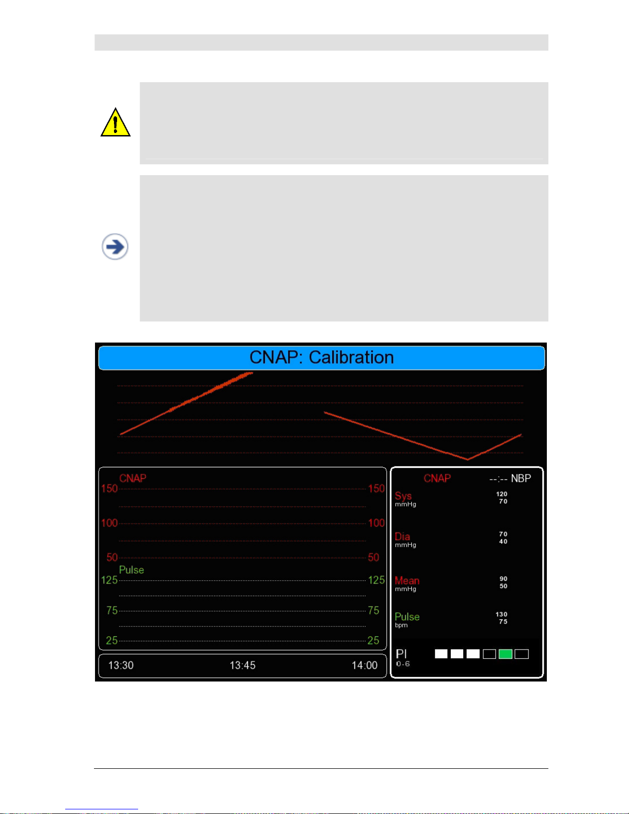
d) During the initialization of CNAP measurement, at the start of measuring or change
of finger, the non-calibrated and then the measured blood pressure signal will be
displayed (blood pressure waveform – see illustration 20 below). In order to avoid
misinterpretation, the scale of the blood pressure waveform will be blanked in the
meantime.
Illustration 20: CNAP calibration
Page 32
Monitor configuration
CNAP™ Monitor 500 Page 4-6 Version 3.5.1, PN: 21-FHZU-10002
4.5 Interfaces (optional)
On the right side of the CNAP™ Monitor 500, the following connectors can be found (see chapter 3.2.1
- illustration 2):
4.5.1 AUX Analog Out (analog output port)
The AUX Analog Out (analog output port) is only available for the CNAP™ Monitor 500at. The corrected CNAP™ blood pressure waveform is available from the device's analog output port (see chapter
15.2 - Connections).
4.5.2 Ethernet
The CNAP™ Monitor 500 may be connected to a PC via Ethernet standard in future; at present, the
Ethernet port is deactivated.
4.5.3 USB
In addition to service functions such as software updates, the USB port serves for data recording on
the USB device, provided that
Record
for data recording has been activated in
Setup/Monitor
(
User
or
Debug
). The settings for
Record
cannot be changed during a measurement.
Procedure for activating
Record
for data recording on the USB device:
1. Prepare a USB stick with the following specifications:
• ‘Corsair Flash Voyager’ 4GB recommended
• Not read-only
• FAT32 formatted (not NTFS)
• Old data deleted
2. Turn off the CNAP™ Monitor 500
3. Connect USB stick
4. Turn on the CNAP™ Monitor 500
5. Open the monitor menu in
Setup/Monitor
and select one of the following settings for re-
cording:
Note: The
Debug
setting is always to be used in the event of clinical studies.
6. Back to
Main Screen
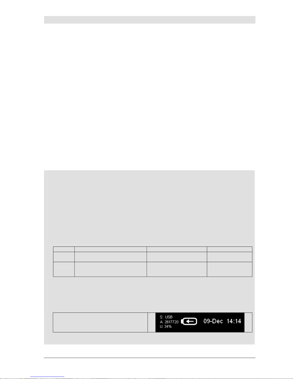
7. Check if the USB stick properties are displayed in the top right of the screen.
S: USB connected
A: Available, free capacity in MByte
U: Stored capacity
In the event of failed activation, status messages will be displayed (see 12.1.2 – Status Messages).
Setting Use Parameters Capacity
User Clinical focus: Data backup for
inspection
CNAP (waveform + trend),
NBP, pulse, time
approx. 10 MB/h
(4GB = 400h)
Debug Validation focus: Clinical and
technical evaluation (studies,
internal)
Further technical parameters
approx. 180 MB/h
(4GB = 22h)
Page 33

Monitor configuration
CNAP™ Monitor 500 Page 4-7 Version 3.5.1, PN: 21-FHZU-10002
NOTE:
• If the shutdown procedure of the CNAP™ Monitor 500 is interrupted by releasing the
Power On/Off Button to early, the error message “No USB Stick Attached” may occure even if the USB media is placed correctly. In this case the USB media must be
reconnected to mount the device correctly.
Page 34
Management of patient data
CNAP™ Monitor 500 Page 5-1 Version 3.5.1, PN: 21-FHZU-10002
5 Management of patient data
Patient entry.........................................................................................................................5-1
Editing of patient data............................................................................................................5-3
Discharge.............................................................................................................................5-3
Immediately after a patient has been connected to the CNAP™ Monitor 500 and the setup process has
been performed correctly (see chapter 3.5 - Patient setup), the
Setup Patient
dialog for selecting
the patient category opens automatically. After selecting the correct patient category, the measurement starts automatically.
NOTE:
• With regard to the safe operation of the CNAP™ Monitor 500 as well as the unambi-
guous identification and classification of measurements and prints, the input of patient data is a prerequisite of essential importance. Entering the respective patient
category, for instance, results in the subsequent adjustment of alarm limits as well as
of the NBP cuff inflation pressure.
5.1 Patient entry
Patient entry and use of current patient data is done via the setup patient dialog appearing on the
main screen immediately after a new patient has been set up with the CNAP™ double finger cuff.
NOTE:
• The
Setup Patient
dialog will be displayed automatically if a new patient is meas-
ured or if the CNAP™ double finger cuff was not applied for ≥ 5 seconds. In case the
Setup Patient
dialog is not displayed automatically despite correct application of
the CNAP™ double finger cuff (detection error) or if the measurement is continued, it
is displayed by pressing the
Start/Stop
key.
Page 35
Management of patient data
CNAP™ Monitor 500 Page 5-2 Version 3.5.1, PN: 21-FHZU-10002
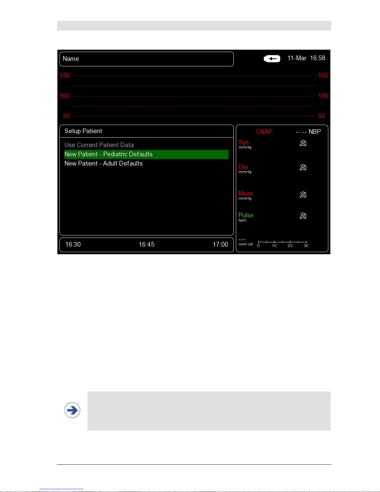
Illustration 21: Setup Patient Dialog
There are 2 ways for setup a patient before starting a measurement:
a) New Patient:
Selecting the functions
New Patient – Adult Defaults
or
New Patient – Pediat-
ric Defaults
automatically sets the respective patient category (adult, pediatric). Preset-
ting of the focus on
New Patient – Adult Defaults
or
New Patient – Pediatric
Defaults
can be defined in
Setup/Measurement/Patient Category
. As soon as a
category is selected, measurement starts automatically.
b) Use Current Patient Data (continue):
The
Use Current Patient Data
option can be selected in the
Setup Patient
dialog
provided that a patient category has already been defined (current patient data is being
used). After confirming the
Use Current Patient Data
option, the measurement will
automatically continue with a new initialization phase.
NOTE:
• While the
Setup Patient
dialog is displayed, it is not possible to complete further
patient data (e.g. name, gender) in the
Patient Data
menu (see chapter 5.2 - Edit-
ing of patient data). In such a case, the
Patient Data
menu will only be accessible
again after selection of a patient category.
Page 36
Management of patient data
CNAP™ Monitor 500 Page 5-3 Version 3.5.1, PN: 21-FHZU-10002
5.2 Editing of patient data
At any given time – except during the display of the
Setup Patient
dialog – you can enter detailed
patient data by using the click-wheel control to select the
Alarm frame
on the main screen and to
open the
Patient Data
menu.
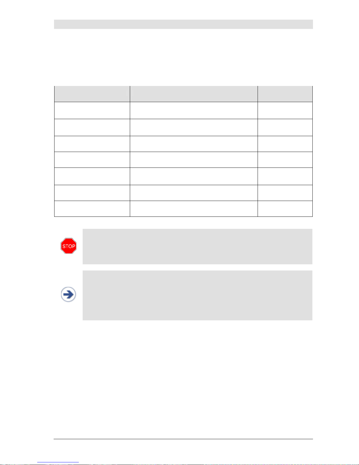
Menu item Description Settings
Name
Patient's surname and first name
(max. 20 characters)
Keyboard (clickwheel control)
ID#
Patient file number, e.g. 12345678
(max. 15 characters)
Keyboard (clickwheel control)
Gender
Patient gender
---, M, F
Birth Date
Patient’s birth date, e.g. 1970-MAR-10
YYYY-MMM-DD
Category
Patient category: ADULT > 14 years
PEDIATRIC 4 – 14 years
Pediatric, Adult
Discharge
Discharge patient information
Yes, No
OK
STOP:
•
Patient category
: Entering the correct patient category is an indispensable pre-
requisite before starting a measurement process. Be sure to select the correct patient
category as this determines the adjustment of alarm limits and the inflation pressure
of the NBP cuff.
NOTE:
• Before applying the CNAP™ finger cuff and during a measurement, the
Patient Da-
ta
menu can be selected via the
Alarm frame
.
• If, before starting a measuring process, you want to enter additional patient data,
you have to do this before applying the finger cuff. By selecting the
Use Current
Patient Data
option in the
Setup Patient
dialog, the currently input patient data
will be used.
5.3 Discharge
As a rule, patient data needs to be deleted when a measurement in a new patient is performed:
The
Discharge
function
• deletes all information in the
Patient Data
menu,
• deletes all trends of data from the monitor,
• deletes all entries of the
Alarm History
.
Page 37

Management of patient data
CNAP™ Monitor 500 Page 5-4 Version 3.5.1, PN: 21-FHZU-10002
After having stopped the measuring process, patient data can be deleted in 2 ways:
a)
Patient Data
menu:
Open the
Patient Data
menu by using the click-wheel control to select the
Alarm frame
on the main screen. Select
Discharge
and confirm your selection in the input dialog.
b) Setup of a new patient:
Immediately after a new patient has been set up with the CNAP™ double finger cuff and the
device’s self-test has been performed, the
Setup Patient
dialog appears on the main
screen. Select
New Patient – Pediatric Defaults
or
New Patient – Adult Defaults
and confirm your choice in the input dialog. This will result in the deletion of any previous patient data.
NOTE:
• In order to avoid loss of patient data, all required data and entries must be printed
before discharging (=deleting patient data) a patient.
•
Discharge
can only be made after the measurement has stopped.
• After
Discharge
,
even before leaving the
Patient Data
menu, new patient data
can be entered for the next patient. In such a case, this patient data will be used in
the following
Setup Patient
dialog by selecting
Use Current Patient Data
.
Page 38
Alarm system
CNAP™ Monitor 500 Page 6-1 Version 3.5.1, PN: 21-FHZU-10002
6 Alarm system
Visual alarm signals...............................................................................................................6-2
Acoustic alarm signals............................................................................................................6-3
Alarm system control.............................................................................................................6-4
Acknowledgement of alarms – Audio Off, Audio Pause ...............................................................6-4
Pausing/switching off alarms – Alarms Paused, Alarms Off .........................................................6-4
Reactivation of paused alarms - Alarms Off ..............................................................................6-5
Alarm limits ..........................................................................................................................6-5
Display of individual alarm limits .............................................................................................6-5
Alarm setup..........................................................................................................................6-5
Auto limits............................................................................................................................6-7
Alarm limits – factory settings.................................................................................................6-7
Alarm history........................................................................................................................6-8
Alarm system function tests....................................................................................................6-9
Physiological alarms ..............................................................................................................6-9
The alarm system of the CNAP™ Monitor 500 distinguishes between two alarm levels: physiological
alarms (yellow) and technical malfunction alarms (white).
• MEDIUM PRIORITY: **
Yellow alarms are physiological alarms of medium priority (e.g. exceeding the upper or falling below the lower limit for systolic blood pressure).
• LOW PRIORITY: *
Technical malfunction alarms indicate that the CNAP™ Monitor 500 is unable to take a measurement or to reliably detect possible alarm conditions. Instead of numeric values, the
Parameter
frame
displays three stars (***), accompanied by an acoustic signal which has to be confirmed
by the operator (see chapter 6.3.1 – Acknowledgement of alarms). Depending on the indicated
malfunction, the operator may have to take a measure (e.g. replace a defective CNAP™ double finger cuff).
NOTE:
• The CNAP™ Monitor 500 has no other than the mentioned 2 alarm levels: physiologi-
cal alarms (yellow) and technical malfunction alarms (white).
• Physiological alarms are deleted:
- by
Discharge
,
- by stopping the measurement using
Start/Stop
,
- by the next NBP measurement.
• Physiological alarms triggered by a single NBP measurement will be saved until the
next NBP measurement.
STOP:
If several alarms are activated at the same time:
• The alarm signals will be displayed alternately in intervals of 5 seconds in the
Pa-
rameter frame
,
• Physiological alarms and technical malfunction alarms will be displayed one after the
other in their order of appearance,
• The physiological alarm with the highest priority will be accompanied by an acoustic
signal,
• New alarms and technical malfunction alarms will be displayed immediately.
Page 39
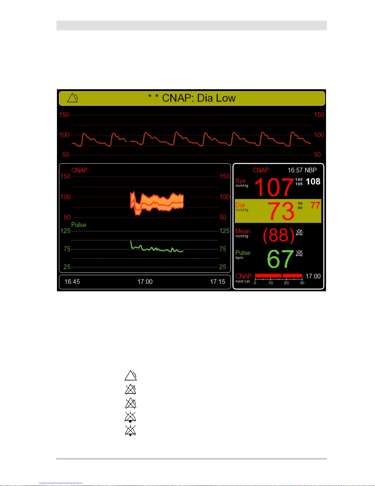
Alarm system
CNAP™ Monitor 500 Page 6-2 Version 3.5.1, PN: 21-FHZU-10002
6.1 Visual alarm signals
Alarm signals are displayed visually in the
Alarm frame
and the
Parameter frame
,
directly in
the main screen. In the
Parameter frame
, only those parameters are visually marked which ex-
ceed the defined alarm limits.
Illustration 22: Visual alarm signals
Alarm frame:
• Background color: YELLOW - Physiological alarms (medium priority)
WHITE - Technical malfunction alarms (low priority)
BLUE - Status messages
• Alarm priority: ** - medium priority
* - low priority
• Alarm system status:
- Alarm
- Alarms Paused
- Alarms Off
- Audio Pause
- Audio Off
Page 40
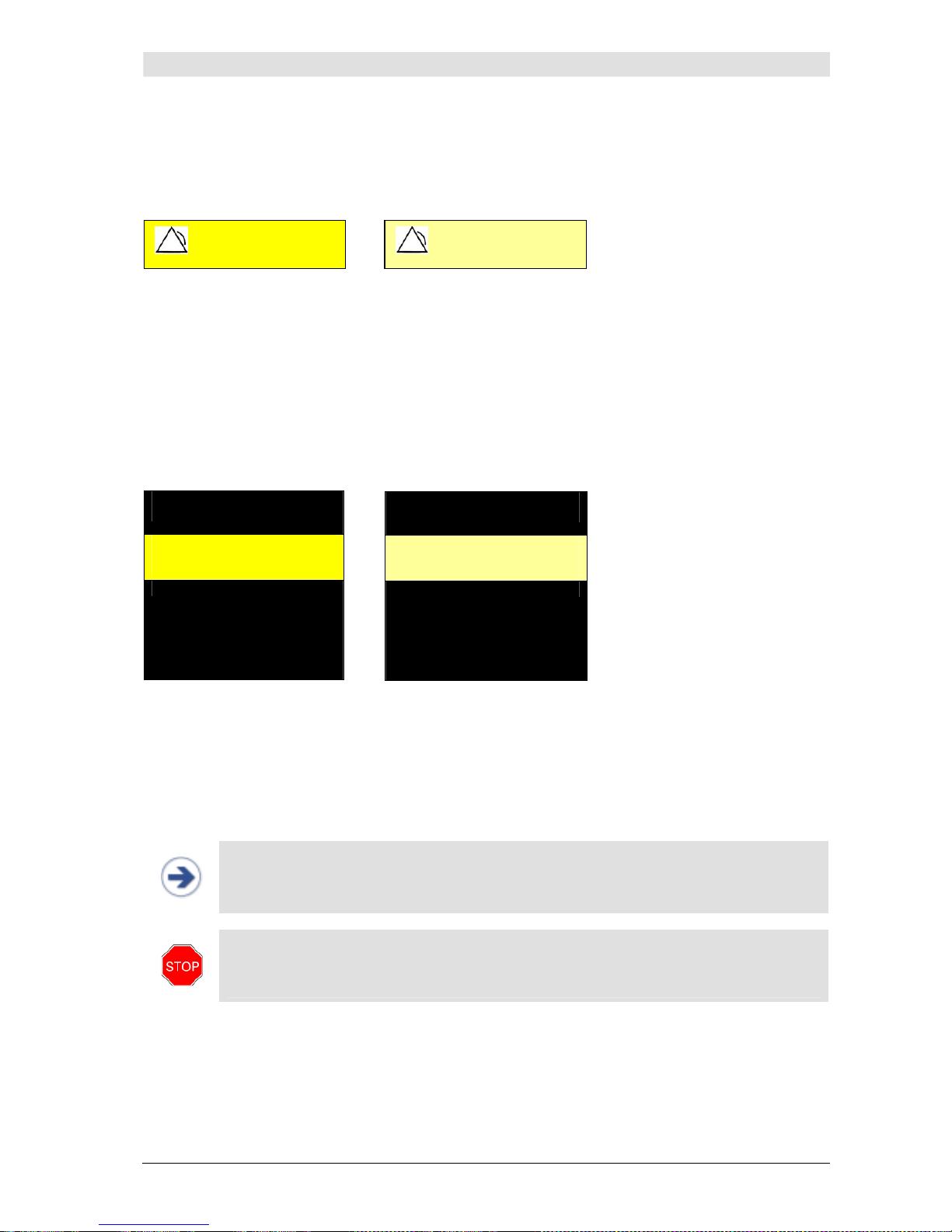
Alarm system
CNAP™ Monitor 500 Page 6-3 Version 3.5.1, PN: 21-FHZU-10002
• Alarm message: a text with an alarm message describing the cause for the alarm signal appears in
the
Alarm frame
.
• Flashing
Alarm frame
for physiological alarms
Illustration 23: Alarm frame – alarm conditions
Parameter frame
:
• Background color: YELLOW – Physiological alarms (medium priority)
WHITE - Technical malfunction alarms (low priority)
BLUE - Status messages
• Flashing parameters which are exceeding the alarm limits
• Numeric values: unchanged during physiological alarms, blanked during technical malfunction
alarms by 3 stars (***).
Illustration 24: Parameter frame – alarm conditions
6.2 Acoustic alarm signals
In accordance with the regulations of EN 60601-1-8, the CNAP™ Monitor 500 produces acoustic alarm
signals. The differently coded alarm signals are repeated until acknowledged by pressing the
Alarm
Pause/Off
key.
NOTE:
Repetition rate for acoustic alarm signals is:
• 5 seconds for physiological alarms,
• 18 seconds for technical malfunction alarms.
STOP:
• Do not rely solely on the acoustic alarm signals! Especially if the alarm volume is set
low or has been turned off, alarms might be missed which could constitute a possible
danger for patients!
The alarm signal volume is individually adjustable. Factory setting is 80% of maximum volume and
can be adjusted from 20 to 100%. Maximum sound pressure amounts to 93 dB at a distance of 1 meter from the CNAP™ Monitor 500, whereas minimum sound pressure amounts to 60 dB at a distance
of 1 meter from the device.
CNAP
130
CNAP
130
** CNAP: Sys High ** CNAP: Sys High
Sys
mmHg
75
(98)
Dia
mmHg
Mean
mmHg
Sys
mmHg
75
(98)
Dia
mmHg
Mean
mmHg
Page 41
Alarm system
CNAP™ Monitor 500 Page 6-4 Version 3.5.1, PN: 21-FHZU-10002
6.3 Alarm system control
6.3.1 Acknowledgement of alarms – Audio Off, Audio Pause
In order to acknowledge all activated alarms (physiological and technical malfunction alarms), press
Alarm Pause/Off
once.
Depending on the respective settings of the
Alarm Reminder
feature, the status message
Audio
Off
or
Audio Pause
is displayed.
ALARM REMINDER: If the alarm reminder is activated in the monitor setup, a repeated acoustic signal
reminds the operator of alarm conditions that continue to exist after acknowledgement of the alarm
signal by the operator. This acoustic reminder may be repeated for a limited or unlimited amount of
time.
Menu item Description Settings
Alarm Reminder
Setting of alarm reminder
off, 1 min, 2 min, 3 min
NOTE:
• During measurements, an alarm reminder setting may be entered in the
Parame-
ter
menu by using the click-wheel control to open the
Parameter frame
. The set-
tings are saved by confirming with
Alarm Pause/Off
.
• The alarm reminder operator setting may be set in the
Alarm defaults
menu,
which is opened from the
Service
menu by using the click-wheel control.
6.3.2 Pausing/switching off alarms – Alarms Paused, Alarms Off
In order to temporarily deactivate (= pause) physiological alarms, press
Alarm Pause/Off
twice.
Temporarily no physiological alarms will be activated, e.g. when a patient is being relocated. Depending on the
Audio Pause
settings, either the status
Alarms Off
or
Alarms Paused
is displayed.
ALARM PAUSE: Depending on the monitor configuration, the alarms may be paused for a limited or
unlimited time. Hence selecting an alarm pause of an unlimited amount of time equals switching off
the alarm signal altogether.
Menu item Description Settings
Alarm Pause
Setting of alarm pause
1 min, 2 min, 3 min,
no timeout
NOTE:
• Pausing alarms is only possible if no physiological alarms are activated.
• During measurements,
Alarm Pause
setting changes will only become active with
the next activated alarm pause, i.e. after restart of the alarm system (see chapter
6.3.3 – Reactivation of paused alarms) and reactivation of paused alarms by pressing
Alarm Pause/Off
twice.
• Technical malfunction alarms or malfunction reports are displayed even when the
function
Alarm Pause
has been activated.
NOTE:
• During temporary alarm pauses, the remaining pause time is displayed in the
Alarm
frame
.
• In case of a temporally unlimited alarm pause, the
Alarm frame
displays the mes-
sage
Alarms Off
.
Page 42
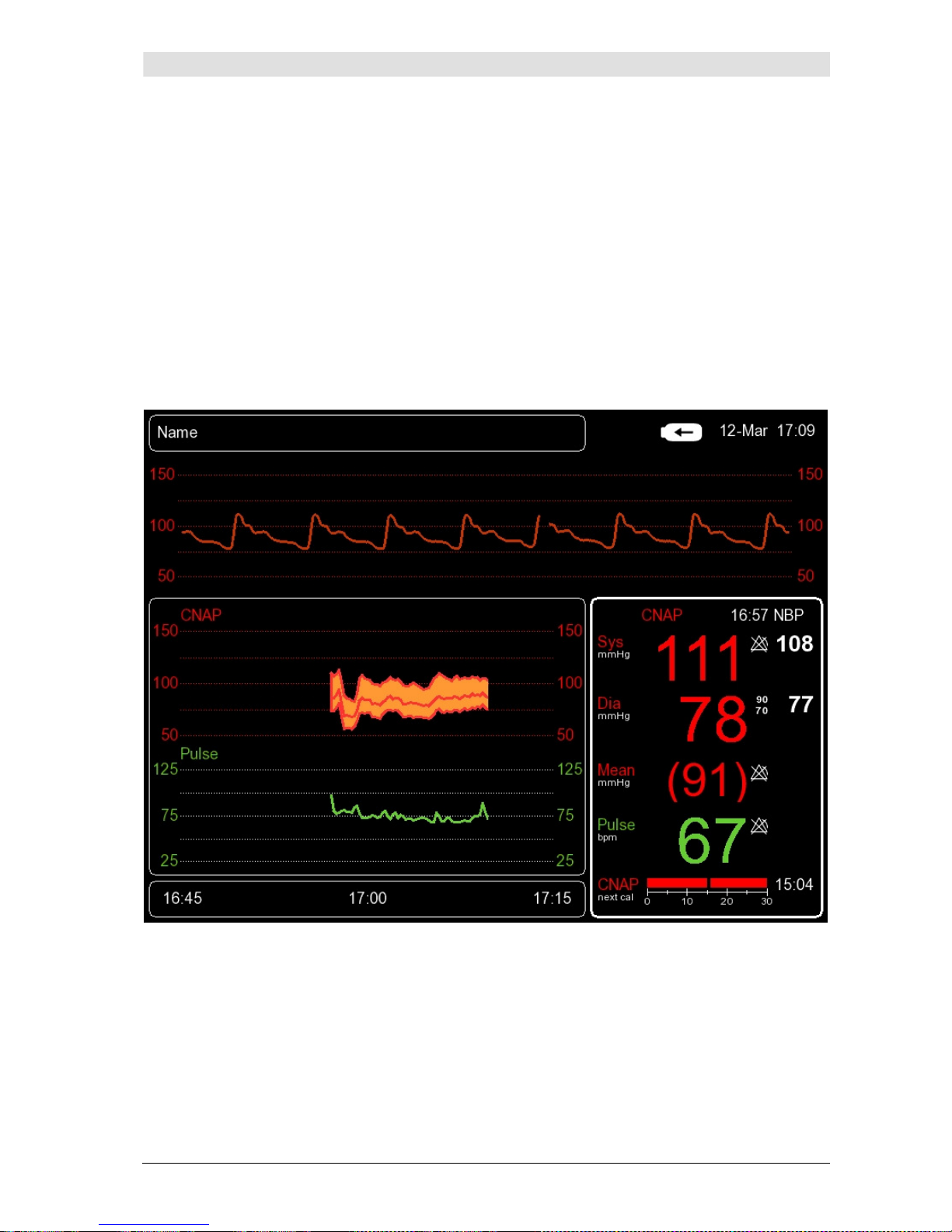
Alarm system
CNAP™ Monitor 500 Page 6-5 Version 3.5.1, PN: 21-FHZU-10002
6.3.3 Reactivation of paused alarms - Alarms Off
In order to reactivate alarms having been paused for an unlimited amount of time, press
Alarm
Pause/Off
three times.
6.4 Alarm limits
Alarm limits set the alarm conditions for physiological alarm signals.
6.4.1 Display of individual alarm limits
The preset alarm limits (upper, lower) of every measuring parameter are displayed beside the respective measured value in the
Parameter frame
of the main screen. If a parameter's alarm function is
deactivated, the symbol for
Alarms Off
will appear next to the measured value in the
Parameter
frame
(refer to chapter 6.1 – Visual alarm signals).
Illustration 25: Parameter frame – alarm limits
In order to view and edit all set alarm limits, use the click-wheel control to select the
Parameter
frame
and then to open the
Alarm Limits
menu (see chapter 6.4.2 – Alarm setup).
6.4.2 Alarm setup
The
Alarm Limits
menu, which is opened from the
Parameter frame
by means of the click-
wheel control, enables the operator to adjust the alarm functions of all parameters.
Page 43
Alarm system
CNAP™ Monitor 500 Page 6-6 Version 3.5.1, PN: 21-FHZU-10002
Menu item Description Settings
Auto Limits
Automatic setting of alarm limits for activated
alarms
Narrow, Wide,
Cancel, Off
Sys
Alarm limits for systolic blood pressure
On, Off;
upper, lower
Dia
Alarm limits for diastolic blood pressure
On, Off;
Upper, Lower
Mean
Alarm limits for mean blood pressure
On, Off;
Upper, Lower
Pulse
Alarm limits for pulse rate
On, Off;
Upper, Lower
Alarm Volume
Volume settings for alarms, 20 – 100%
20(20)100
Alarm Reminder
Function to set alarm reminders (see chapter 6.3.1
– Acknowledgement of alarms - Audio Off, Audio
Pause)
Off, 1 min, 2
min, 3 min
Alarm Pause
Pausing of alarms (see chapter 6.3.2 – Pausing
/switching off alarms –
Alarms Paused
,
Alarms Off
)
1 min, 2 min, 3
min, no timeout
NOTE:
• The defined safe limits configured in the factory settings never leave the physiological
area.
Sys, Dia, Mean, Pulse
: Setting of alarm function for every single parameter:
•
On, Off
• Lower: lower limit
• Upper: upper limit
• Current: Display of current numeric value of a given vital parameter
STOP:
• The CNAP™ Monitor 500 determines the alarm limits on the basis of the entered pa-
tient category. Thus, be sure to enter the correct patient category before starting a
measurement.
• The operator can adjust alarm limits within the
Alarm defaults
menu. Alarm limit
settings for the patient categories
Adult
and
Pediatric
are to be performed separately. The respective menu is located in a password protected area of the CNAP™
Monitor 500, which can be accessed via the
Service
menu. The necessary password
as well as further information about configuring individual user settings or restoring
factory settings can be found in the CNAP™ Monitor 500 “Service manual for users“.
STOP:
• The parallel use of different alarm settings for the same device (or similar instruments)
used in different areas (e.g. in the intensive care unit or in cardiac surgery) might constitute a possible danger for patients.
Page 44
Alarm system
CNAP™ Monitor 500 Page 6-7 Version 3.5.1, PN: 21-FHZU-10002
6.4.3 Auto limits
By means of the function
Auto limits
,
the operator is able to adjust alarm limits to a specific patient. Therefore, it is necessary to wait for the monitor to display physiological signals of a measurement in order to be able to activate
Auto limits
.
Later, if patient data is deleted or new patient data
is entered, the function
Auto limits
will be deactivated automatically.
Using this function leads to the alarm limits of activated alarms being adjusted to the currently measured vital parameters. The alarm limits will then be set within a predefined safety range based on the
measured individual parameters:
•
Narrow:
currently measured value Sys/Dia/Mean/Pulse ± 20mmHg
•
Wide:
currently measured value Sys/Dia/Mean/Pulse ± 30mmHg
•
Cancel:
return to
Alarm limits
menu without changing the alarm limits
•
Off:
alarm limits are restored to user settings
(
Alarm defaults
).
Alarm limits set by means of
Auto limits
are based on the patient's parameters measured at the
time of function activation.
6.4.4 Alarm limits – factory settings
The CNAP™ Monitor 500 has been preset to the following factory settings and default settings for
alarm limits, which apply to both CNAP™ and NBP.
• Alarm limits (ADULT):
Lower limits Upper limits
Parameter Lower limits Defaults Upper limits Lower limits Defaults Upper limits
sBP
[mmHg]
40 90 255 45 140 260
dBP
[mmHg]
30 50 245 35 90 250
mBP
[mmHg]
35 60 250 40 110 255
Pulse
[bpm]
30 50 195 35 110 200
Page 45
Alarm system
CNAP™ Monitor 500 Page 6-8 Version 3.5.1, PN: 21-FHZU-10002
• Alarm limits (PEDIATRIC):
Lower limits Upper limits
Parameter Lower limits Defaults Upper limits Lower limits Defaults Upper limits
sBP
[mmHg]
40 70 175 45 120 180
dBP
[mmHg]
30 40 165 35 70 170
mBP
[mmHg]
35 50 170 40 90 175
Pulse
[bpm]
30 75 195 35 130 200
NOTE:
• The operator can adjust alarm limits within the
Alarm defaults
menu. Alarm limit
settings for the patient categories
Adult
and
Pediatric
are to be performed separately. The respective menu is located in a password protected area of the CNAP™
Monitor 500 which can be accessed via the
Service
menu. The necessary password
as well as further information about configuring individual user settings or restoring
factory settings can be found in the CNAP™ Monitor 500 “Service manual for users“.
• The user can restore all adjusted
Alarm limits
back to factory settings. To do this,
the user has to select the function
Restore Factory Settings
which can be ac-
cessed via the password protected
Service
menu (see "Service manual for users").
STOP:
• Setting the
Alarm limits
to extreme and thus unsuitable values results in the alarm
system becoming useless!
6.5 Alarm history
The
Alarm History
is displayed directly on the main screen and is a list of up to 100 last released
alarms and malfunction reports. In order to view the
Alarm History
,
use the click-wheel control to
first select
Trend frame
and then to open
Alarm History
.
Each report of the alarm history in-
cludes the following information:
• Date
• Time
• Priority: ** (MEDIUM priority)
• Alarm message
All entries in the
Alarm History
will be deleted either if the CNAP™ Monitor 500 is switched off or if
there is a total loss of power supply (e.g. empty battery + no mains power supply).
Page 46
Alarm system
CNAP™ Monitor 500 Page 6-9 Version 3.5.1, PN: 21-FHZU-10002
6.6 Alarm system function tests
When the CNAP™ Monitor 500 is switched on, the alarm system automatically performs a self-test in
the course of which the operator has to check the functional reliability of all acoustic and visual alarm
signals.
6.7 Physiological alarms
Alarm message Priority Source Description Alarm signals
NBP: Sys High
NBP: Dia High
Medium** NBP Measured NBP pressure value
exceeds upper alarm limit. In
addition, "Sys", "Dia" indicates
which parameter has exceeded
the alarm limit.
Flashing NBP
values, alarm
message and
acoustic alarm
signal
NBP: Sys Low
NBP: Dia Low
Medium** NBP Measured NBP pressure value
falls below lower alarm limit. In
addition, "Sys", "Dia" indicates
which parameter has dropped
below the alarm limit.
Flashing NBP
values, alarm
message and
acoustic alarm
signal
CNAP: Sys High
CNAP: Dia High
CNAP: Mean High
Medium** CNAP™ Measured CNAP™ pressure val-
ue exceeds upper alarm limit. In
addition, "Sys", "Mean", "Dia"
indicates which parameter has
exceeded the alarm limit.
Flashing
CNAP™ values,
alarm message
and acoustic
alarm signal
CNAP: Sys Low
CNAP: Dia Low
CNAP: Mean Low
Medium** CNAP™ Measured CNAP™ pressure val-
ue falls below lower alarm limit.
In addition, "Sys", "Mean", "Dia"
indicates which parameter has
fallen below the alarm limit.
Flashing
CNAP™ values,
alarm message
and acoustic
alarm signal
CNAP: Pulse High
Medium** CNAP™ Pulse rate (CNAP™) exceeds
upper alarm limit.
Flashing
CNAP™ values,
alarm message
and acoustic
alarm signal
CNAP: Pulse Low
Medium** CNAP™ Pulse rate (CNAP™) falls below
lower alarm limit.
Flashing
CNAP™ values,
alarm message
and acoustic
alarm signal
STOP:
The automatic device self-test causes the system to release a technical alarm signal of
LOW priority (white alarm), the alarm message reading
Alarm Self-Test
.
Check the
functional reliability of the alarm system during start-up of the monitor and confirm it by
pressing
Alarm Pause/Off
:
• Visual alarm signal: * Alarm message:
Alarm Self-Test
• Acoustic alarm signal: LOW PRIORITY
Page 47

Alarm system
CNAP™ Monitor 500 Page 6-10 Version 3.5.1, PN: 21-FHZU-10002
NOTE:
• All technical malfunction alarm messages of the CNAP™ Monitor 500 or its components
can be found directly in the chapters describing the respective system components.
Page 48
CNAP™ Monitor 500 Page 7-1 Version 3.5.1, PN: 21-FHZU-10002
Tr
ends
7 Trends
Trend - the menu for display options .......................................................................................7-2
Setup ..................................................................................................................................7-3
Trend views..........................................................................................................................7-3
Graphic trend........................................................................................................................7-3
Numeric trend.......................................................................................................................7-6
Alarm history........................................................................................................................7-7
Scrolling of trend views..........................................................................................................7-8
The CNAP™ Monitor 500 automatically displays the parameters
Sys, Mean, Dia
and
Pulse
in the
Trend frame
on the main screen. Trends can be displayed as graphic as well as numeric trends.
The display of a list of physiological alarms is optional.
NOTE:
• The recorded parameters
Sys, Mean, Dia
and
Pulse
are saved on a beat-to-beat-
basis for a maximum of 24 hours.
• Saved recordings can be displayed in the
Trend frame
at any time (see chapter
7.2.1 – Trend views).
STOP:
•
Discharge:
When a patient is discharged, all recorded data, including the parame-
ters
Sys, Mean, Dia
and
Pulse
as well as the
Alarm History
are irretrievably
deleted.
•
Print report
:
The setup and configuration of the
Trend frame
also determine the
selection and the display of the
print reports (Graphic Trend Report, Nu-
meric Trend Report
and
Alarm History Report).
Thus, before starting a
print report
, make sure that the data in the
Trend frame
display is equivalent
to the data you wish to include in your print report concerning, for instance, amplitude, time scale and displayed time span (see chapter 8 – Printing).
Page 49
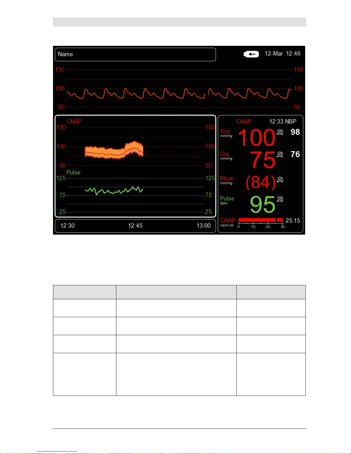
CNAP™ Monitor 500 Page 7-2 Version 3.5.1, PN: 21-FHZU-10002
Tr
ends
Illustration 26: Trend frame
7.1 Trend – the menu for display options
The
Trend (Display Options)
menu, which can be accessed directly from the main screen by
means of the click-wheel control, allows the operator to configure trend views in the
Trend frame.
Menu item Description Settings
Trend Display
Selection of trend view:
Graphical
or
Nu-
meric
display or
Alarm History
Graphical, Numeric,
Alarm History
BP Scale…
Adjustment of amplitude scales of CNAP™
blood pressure waveform and trend
BP Mean,
BP Amplitude
Pulse Scale…
Adjustment of amplitude scales of pulse rate
trends
Pulse Mean,
Pulse Amplitude
Time Scale...
Setting of time scale
Graphic:
30min (default), 1h,
2h, 4h, 8h, 12h, 24h
Numeric:
1 beat, 1min, 5min,
15min, 30min, 1h
Page 50
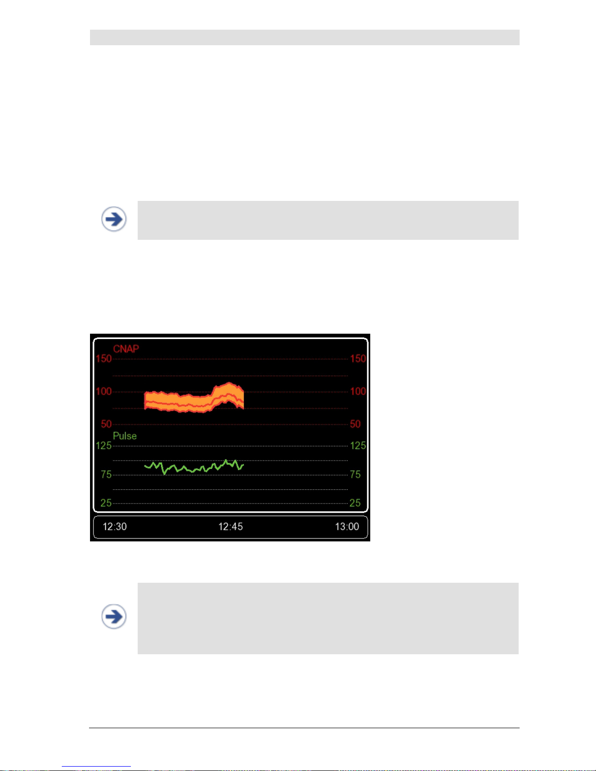
CNAP™ Monitor 500 Page 7-3 Version 3.5.1, PN: 21-FHZU-10002
Tr
ends
7.2 Setup
7.2.1 Trend views
Recorded data are automatically displayed in the
Trend frame
on the main screen, including three
Trend Display
options:
•
Graphical
:
graphic trend of measured parameters, displayed on a time axis
•
Numerical:
numeric trend of measured parameters in adjustable time limits
•
Alarm History:
display of all alarms issued during a measurement
NOTE:
• You can select your trend display option by using the click-wheel control to open the
Trend frame
on the main screen and access the
Trend Display
menu item.
7.2.2 Graphic trend
The
Graphic Trend Display
allows a graphic view of the following parameters on a time axis:
• CNAP™ blood pressure values: Sys, Dia, Mean
• CNAP™: Pulse
Illustration 27: Graphic Trend Display
NOTE:
• The
Graphic Trend Display
can be adjusted by changing the following scales:
BP Scale, Pulse Scale
and
Time Scale
.
• The displayed data dialog can be adjusted by means of the click-wheel control in the
Navigation frame
(see chapter 7.2.5 – Scrolling of trend views), which also de-
termines the amount of data to be printed.
Page 51
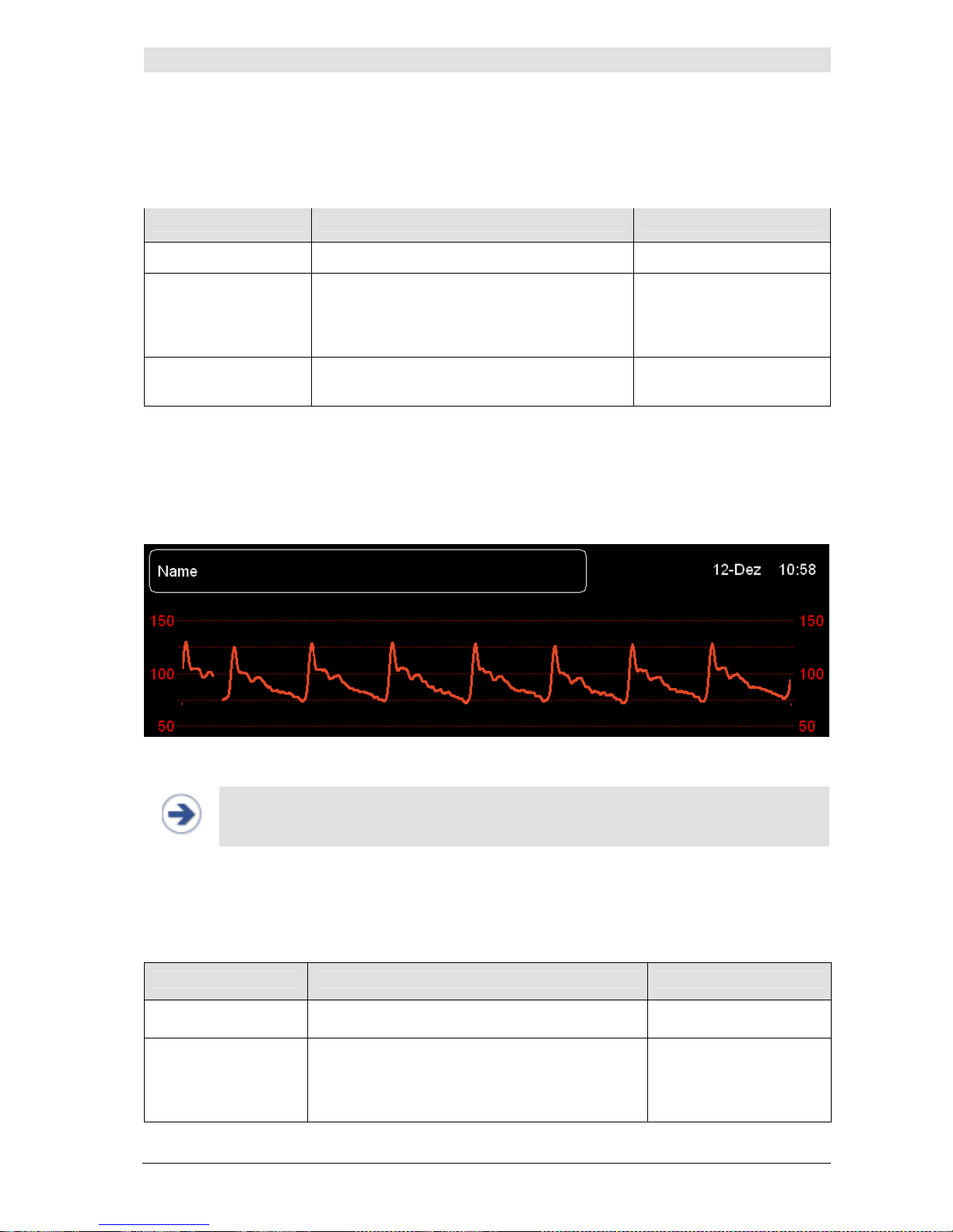
CNAP™ Monitor 500 Page 7-4 Version 3.5.1, PN: 21-FHZU-10002
Tr
ends
BP SCALE:
The scale factor of the CNAP™ blood pressure trend can be configured in the
BP Scale
menu item
which is located in the
Trend
menu. Scales are configured as follows:
Menu item Description Settings
BP Scale …
BP Mean
Setting of expected mean blood pressure
20(10)240 mmHg*
50(25)200 mmHg**
100(50)150
mmHg***
BP Amplitude
Setting of expected blood pressure amplitude
40*, 100**, 200***
mmHg
Example:
Patient's blood pressure: 130 / 80 (105)
o BP Mean: 100 mmHg
o BP Amplitude: 100 mmHg
Illustration 28: Example of BP scale
NOTE:
• The scaling of the CNAP™ blood pressure waveform occurs analogously with the scal-
ing of the CNAP™ trends.
PULSE SCALE:
The scale factor of the CNAP™ pulse rate trend can be configured in the
Pulse Scale
menu item
which is located in the
Trend
menu. Scales are configured as follows:
Menu item Description Settings
Pulse Scale…
Pulse Mean
Setting of expected mean pulse rate
20(10)240 bpm*
50(25)200 bpm**
100(50)150
bpm***
Page 52
CNAP™ Monitor 500 Page 7-5 Version 3.5.1, PN: 21-FHZU-10002
Tr
ends
Menu item Description Settings
Pulse Amplitude
Setting of expected pulse amplitude (max –
min)
40*, 100**, 200***
bpm
TIME SCALE:
The time scale of blood pressure and pulse rate trends can be set in the
Time scale
menu item
which is located in the
Trend
menu.
Menu item Description Settings
Time Scale
Setting of time scale for
Graphic Trend Dis-
play
30min (default),
1h, 2h, 4h, 8h, 12h,
24h
NOTE:
• Time scales of
Graphic Trend Display
always correspond to the entire time slot
which is displayed in the
Trend frame.
• In case of an adjustment of the time scale, the current point of time is displayed on
the right end of the
Trend frame.
STOP:
• Time labels displayed in the
Navigation frame
correspond to the time displayed
on the system clock of the CNAP™ Monitor 500. Therefore, it is essential to make
sure before starting the measuring process that the monitor's system clock is showing the correct time.
Page 53
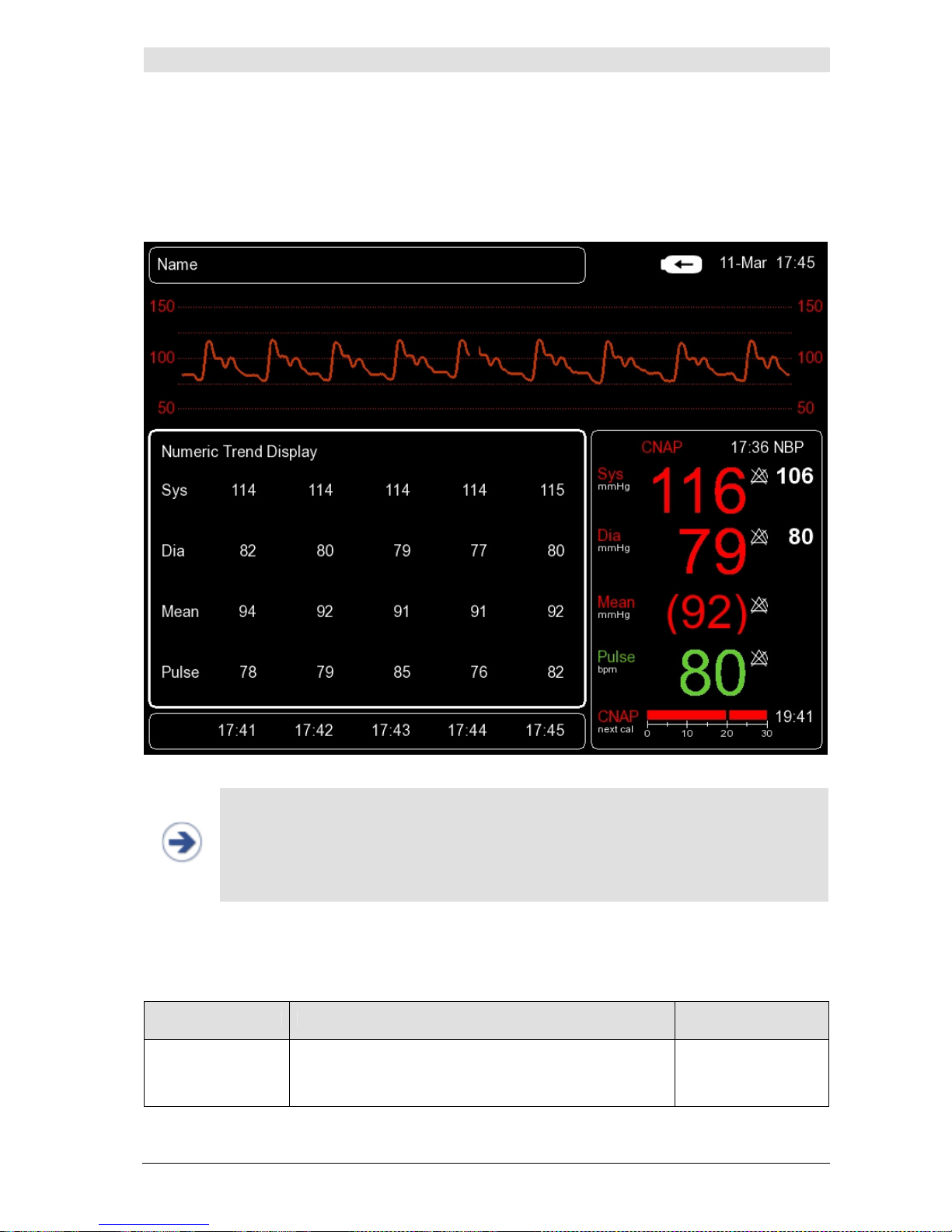
CNAP™ Monitor 500 Page 7-6 Version 3.5.1, PN: 21-FHZU-10002
Tr
ends
7.2.3 Numeric trends
The
Numeric Trend Display
allows a numeric view of the following parameters on a time axis:
• CNAP™ blood pressure values: Sys, Dia, Mean
• CNAP™: Pulse
Illustration 29: Numeric Trend Display
NOTE:
• The
Numeric Trend Display
can be configured by adjusting
Time Scale
from
the
Trend
menu.
• The displayed data dialog can be adjusted by means of the click-wheel control in
Time Scale
in the
Navigation frame
, which also determines the amount of data
to be printed.
TIME SCALE:
The time scale of blood pressure and pulse rate trends can be set in the
Time scale
menu item
which is located in the
Trend
menu.
Menüeintrag Beschreibung Settings
Time Scale
Setting of time scale for
Numeric Trend Display
1beat, 1min,
5min, 15min,
30min, 1h
Page 54
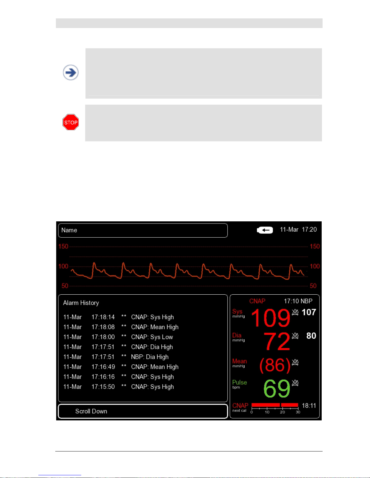
CNAP™ Monitor 500 Page 7-7 Version 3.5.1, PN: 21-FHZU-10002
Tr
ends
NOTE:
• The time scale of the
Numeric Trend Display
corresponds to the time interval
between 2 displayed measured values.
• The displayed values are averaged on the basis of the selected
Time Scale
(time
interval).
• In case of an adjustment of the time scale, the current point of time is displayed in
the far right column of the
Trend frame.
STOP:
• Time labels displayed in the
Navigation frame
correspond to the time displayed
on the system clock of the CNAP™ Monitor 500. Therefore, it is essential to make
sure before starting the measuring process that the monitor's system clock is showing the correct time.
7.2.4 Alarm history
The
Alarm History
is a list of up to 100 last released alarms and malfunction reports. Each report
of the alarm history includes the following information:
• Date
• Time
• Priority
• Alarm message
Illustration 30: Alarm History with entries
Page 55
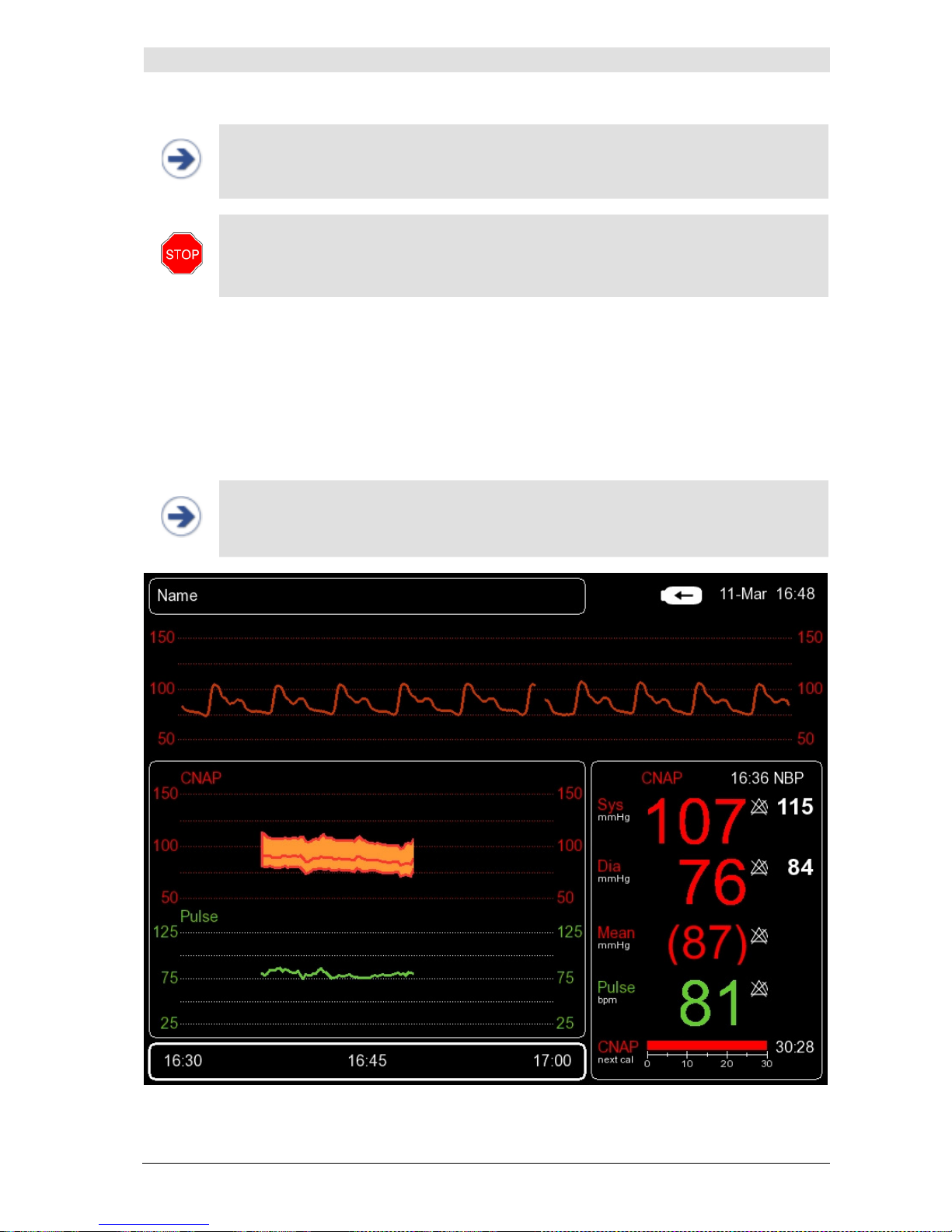
CNAP™ Monitor 500 Page 7-8 Version 3.5.1, PN: 21-FHZU-10002
Tr
ends
NOTE:
• The
Alarm History
includes the entire list of the last reported alarms (up to 100
entries). Therefore,
Time Scale
cannot be selected.
STOP:
• The deletion of patient data irretrievably deletes all connected recordings, including
the parameters
Sys, Mean, Dia
and
Pulse
as well as the
Time Scale
(see chap-
ter 5.3 – Discharge).
7.2.5 Scrolling of trend views
The time slot of the data displayed in the
Trend frame
can be adjusted in the
Navigation frame
by using the click-wheel control:
1) Access the
Navigation frame
using the click-wheel control
2) Select the desired time slot by wheeling the click-wheel control
3) Confirm selection by pressing the click-wheel control
NOTE:
• Scrolling trends by means of the click-wheel control is restricted to the start of a
measurement and/or the current time: i.e., the time slot of a trend can neither be
scrolled to before the start of a measurement nor to a prospective time.
Illustration 31: Navigation frame including time specification
Page 56
Printing
CNAP™ Monitor 500 Page 8-1 Version 3.5.1, PN: 21-FHZU-10002
8 Printing
Launching print reports ..........................................................................................................8-1
Cancelling print reports ..........................................................................................................8-2
Print reports .........................................................................................................................8-2
Print options .........................................................................................................................8-3
The CNAP™ Monitor 500 is provided with an integrated thermal printer, enabling the operator to print
a range of predefined
print reports
.
8.1 Launching print reports
a) Depending on how long the operator presses
Print
he/she can select either
Snapshot
Report
or
Trend Report
:
•
Snapshot Report:
Press Print once for a short time. The blood pressure curve is
printed.
•
Trend Report:
Press Print for longer than 0.5 seconds.
Trend Report
is printed by
corresponding to the data displayed in the
Trend frame.
NOTE:
• The duration of a
Snapshot Report
is limited to 20 seconds.
Snapshot Delay
settings are edited in
Setup/Measurement/Print Options/Snapshot De-
lay.
b) The way recordings are displayed in the
Trend frame (Graphical, Numerical, Alarm
History)
automatically determines the selected
Trend Report
:
•
Graphic Trend Report:
Graphical
(see chapter 8.3 - Print reports)
•
Numeric Trend Report:
Numerical
(see chapter 8.3 - Print reports)
•
Alarm History Report:
Alarm History
(see chapter 8.3 - Print reports)
NOTE:
• Scaling of
Trend frame
: The time slot displayed in the
Trend frame
,
also includ-
ing the time scale settings, is correspondingly printed in the
Trend Report
.
• If necessary, adjust parameter scales BP Scale, Pulse Scale, Time Scale and the dis-
played time slot (
Navigation frame
).
NOTE:
• A
Print On Alarm Report
due to physiological alarm is printed automatically if
Print On Alarm Report
is activated in
Setup/Measurement/Print Op-
tions/Print On Alarm
. In this case, printing does not depend on the
Trend
frame
data display, i.e. BP scale is fixed to 0-250mmHg.
STOP:
• If the CNAP™ Monitor 500 is on battery operation and battery charge status is ≤
25%, printing will be deactivated. Current print tasks will be cancelled immediately
for safety reasons.
Page 57
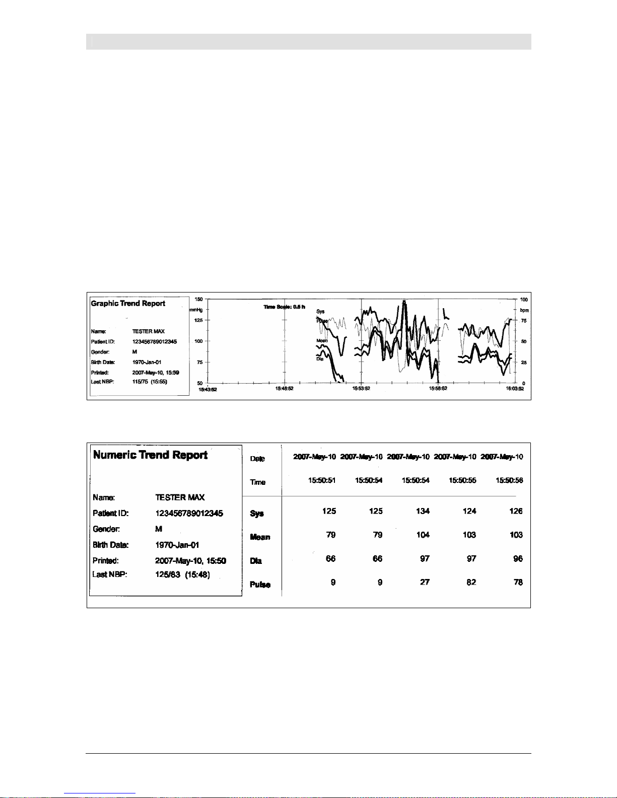
Printing
CNAP™ Monitor 500 Page 8-2 Version 3.5.1, PN: 21-FHZU-10002
8.2 Canceling print reports
In order to cancel print tasks, press
Print
once.
8.3 Print reports
The CNAP™ Monitor 500 offers a range of predefined
print reports
. All
print reports
have the
same header containing the following information:
• Print report type
• Name
• Patient ID
• Gender
• Birth date
• Printed (date and time)
• Last NBP (values and time of the last NBP measurement)
Illustration 32: Graphic Trend Report
Illustration 33: Numeric Trend Report
Page 58
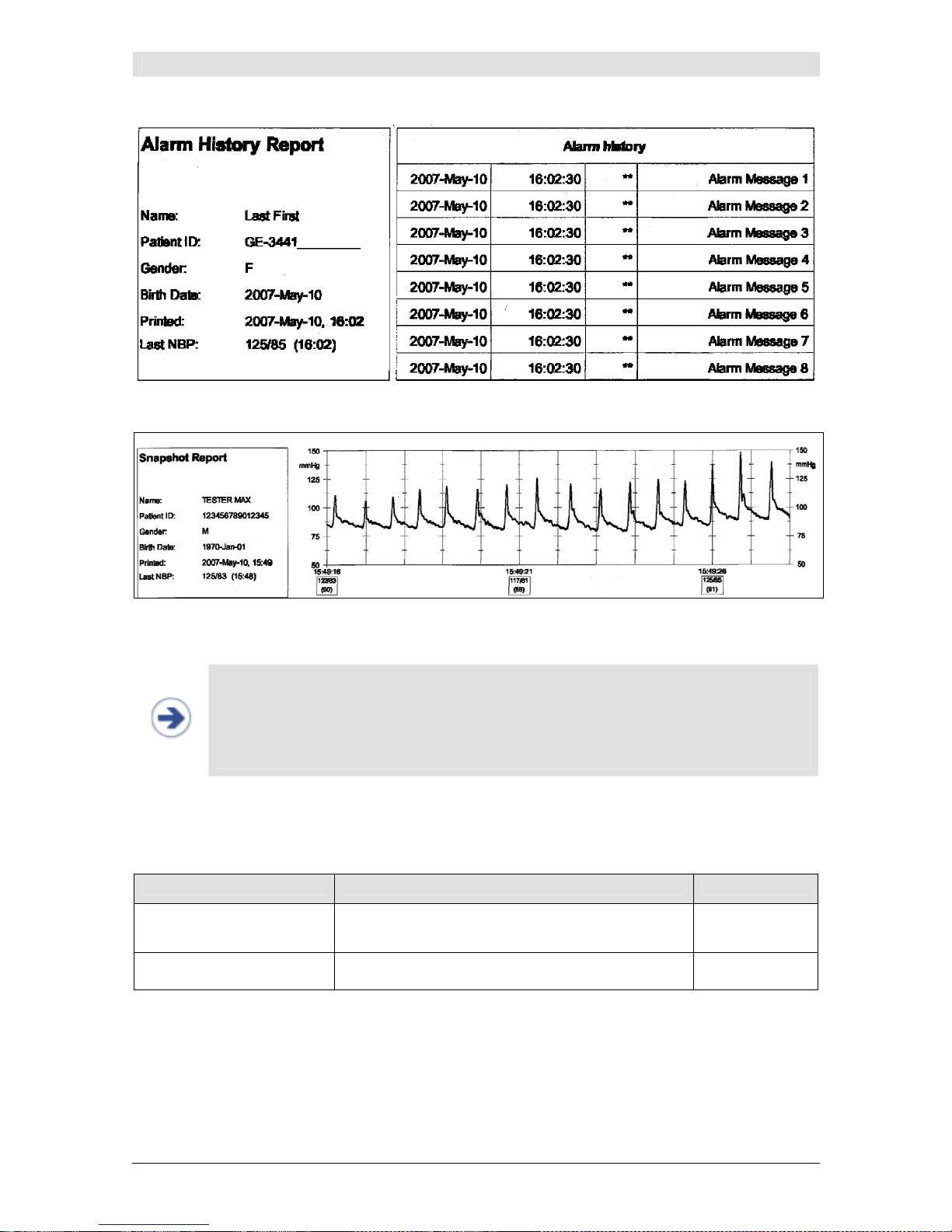
Printing
CNAP™ Monitor 500 Page 8-3 Version 3.5.1, PN: 21-FHZU-10002
Illustration 34: Alarm History Report
Illustration 35: Snapshot report
NOTE:
•
Alarm History Report:
The currently selected alarm as well as the 15 preceding
alarms will be printed.
•
Snapshot Report:
In the case of multiple alarms, a separate snapshot for each
alarm will be printed (last 10 seconds before to 3 seconds after the alarm).
• All reports are uniformly in English.
8.4 Print options
Menu item Description Settings
Snapshot Delay
Setting of delay time of print reports for
Snap-
shot
and
Print On Alarm
5sec, 10sec,
15sec
Print On Alarm
Activation of
Print On Alarm
feature
On, Off
Page 59

CNAP
TM
CNAP™ Monitor 500 Page 9-1 Version 3.5.1, PN: 21-FHZU-10002
9 CNAP™
General information...............................................................................................................9-1
Safety precautions.................................................................................................................9-2
Setup ..................................................................................................................................9-3
View features........................................................................................................................9-4
Blood pressure waveform .......................................................................................................9-4
Trend view ...........................................................................................................................9-4
Numeric values .....................................................................................................................9-5
CNAP™ options .....................................................................................................................9-6
9.1 General information
CNAP™ - Continuous Non-Invasive Arterial Blood Pressure – is a non-invasive method for measuring
the continuous blood pressure waveform in adult and pediatric patients from the age of 4 years.
A patient's blood pressure waveform is recorded by the CNAP™ Monitor 500 by means of a double
finger cuff with an integrated IR light sensor and air chambers. The measured IR signal – similar to a
pulse oximeter – helps to measure the blood volume in the finger, which is kept constant by means of
CNAP: beat to beat a counter pressure in the finger cuff is built up, which fluctuates between the systolic and diastolic blood pressure.
Illustration 36: CNAP™ Technology
By means of NBP cuff (oscillometric blood pressure measurement), the relatively measured blood
pressure in the finger is calibrated to absolute blood pressure values (to the pressure of a big artery at
heart level), thus ensuring absolute accuracy. The NBP cuff can be placed on the patient's upper arm
either on the same or on the other arm as the CNAP™ double finger cuff. NBP measurement is essential to ensure absolute accuracy of the recorded blood pressure values.
CAUTION:
• The accuracy of the CNAP™ measurement depends on the accuracy of the accompa-
nying NBP measurement, which is particularly important during calibrations or before
interventions.
• Make sure that no movement artifacts occur during measurement, especially during
and until approx. 2 min. after measurement initialization.
• Powerful light sources (e.g. cameras with flashlight) may affect the CNAP™ meas-
urement and cause artifacts.
Page 60
CNAP
TM
CNAP™ Monitor 500 Page 9-2 Version 3.5.1, PN: 21-FHZU-10002
CAUTION:
• Movements of the patient, which result in changes of position of the CNAP™ double
finger cuff regarding heart level, will have immediate influence on the absolute values
of blood pressure readings. To compensate these physical effects (hydrostatic
height), recalibrate the CNAP™ measurement by triggering a single NBP measurement (see chapter 10.6 - NBP options).
9.2 Safety precautions
CAUTION:
• Do not use CNAP™ and NBP in patients with vascular prostheses!
• CNAP™ is designed for the concurrent measurement of only one patient at a time.
• Be sure to follow local regulations regarding storage of the CNAP™ Monitor 500, its
accessories and packing material.
• Keep the CNAP™ Monitor 500 out of reach of children!
• The CNAP™ blood pressure waveform is calibrated by means of oscillometric NBP
measurement. If the accuracy of the NBP measurement is affected by artifacts (weak
pulse, irregular pulse, artifacts from patient movement or tremor, or respiratory artifacts), this may also affect and reduce the accuracy of values measured by the
CNAP™ Monitor 500.
• The use of technical surgical devices might cause interference and reduce the quality
of CNAP™ recordings.
• Never connect the device's air connectors to an intravascular system!
• Regularly inspect the patient’s limbs during measurement to avoid possible lasting
damages caused by prolonged impairment of the patient's blood circulation! In case
of any signs of total arterial compression in a finger during measurement, immediately discontinue the measurement process by pressing
Start/Stop
on the front
panel of the CNAP™ Monitor 500.
• Pain or strong feelings of discomfort are in no way normal and are not a part of
CNAP™ measurements! Should a patient report any of these feelings, stop the measurement process immediately!
• Before connecting any cables to a patient, visually inspect all components for dam-
ages or wear. Any faulty parts are to be replaced immediately.
• Check the correct positioning of the CNAP™ double finger cuff regularly during meas-
urement. Make sure that the cuff is not positioned on the finger joints.
NOTE:
• Avoid compressing the air hoses or reducing their diameter in any way (e.g. by bend-
ing the cables) as this could impair the quality of the CNAP™ measurement. To avoid
mechanical damage to the CNAP™ finger cuff, remove all objects (e.g. rings) from
the patient’s fingers before measuring.
STOP:
• The operating environment for CNAP™ hardware has to comply with the directions
regarding ambient temperature, relative humidity and atmospheric pressure.
• Take care to ensure regular and sufficient air circulation around the CNAP™ Monitor
500 by placing the device accordingly (e.g. do not cover it with sheets or blankets).
• In some cases, CNAP measurement is not suitable (see chapter 2.2.2 – Limitations).
Page 61
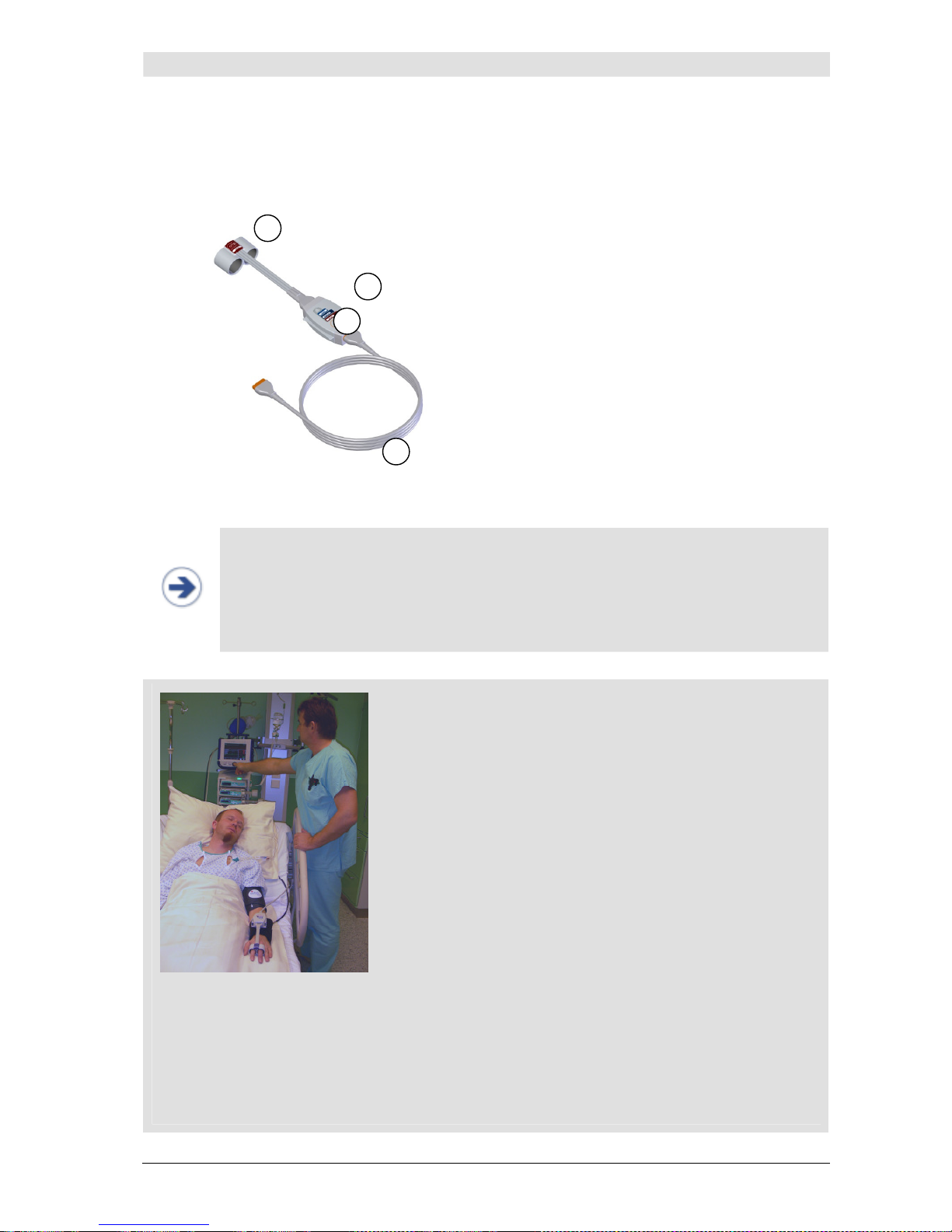
CNAP
TM
CNAP™ Monitor 500 Page 9-3 Version 3.5.1, PN: 21-FHZU-10002
9.3 Setup
The CNAP™ hardware consists of the following components:
CNAP™ double finger cuff
CNAP™ controller
CNAP™ cable
Graphics to select correct finger
cuff size
Illustration 37: CNAP™ hardware
NOTE:
• CNSystems recommends placing the CNAP™ double finger cuff on the index and the
middle finger of a patient. In rare cases – if necessary – the CNAP™ double finger
cuff may also be placed on the middle and the ring finger. Thumb and little fingers
are not suited for CNAP™ blood pressure measurement.
• The use of a too big/too small CNAP™ double finger cuff may result in faulty blood
pressure recordings.
Start/Stop a measurement (refer to chapter 3.5 – Patient setup):
• Choose the correct size of a CNAP™ double finger cuff by
means of the graphics on the upside of the CNAP™ controller
(refer to chapter 3.2.3 - CNAP™ controller).
• Assemble the CNAP™ hardware by connecting the CNAP™
double finger cuff, the CNAP™ controller, the CNAP™ cable and
the CNAP™ Monitor 500. All the plugs and connectors are designed so as to make it impossible to switch them accidentally.
• Equip the patient with the CNAP™ hardware: The CNAP™ dou-
ble finger cuff is placed on the proximal joints of the index and
middle fingers. Make sure that the cuff cables run along the
upper side of the patient's arm.
• Fasten the CNAP™ controller to the patient's forearm by
means of the fixing cuff (with a Velcro fastener).
• Place the NBP blood pressure cuff on the patient's upper arm (calibration for CNAP™) contralat-
erally, or, if necessary, on the same arm as the double finger cuff (refer to chapter 10 – NBP).
• As soon as you have selected a category in the
Setup Patient
dialog, the CNAP™ measure-
ment will start automatically.
1
3
2
4
Abbildung 38:
Patient-setup
Page 62
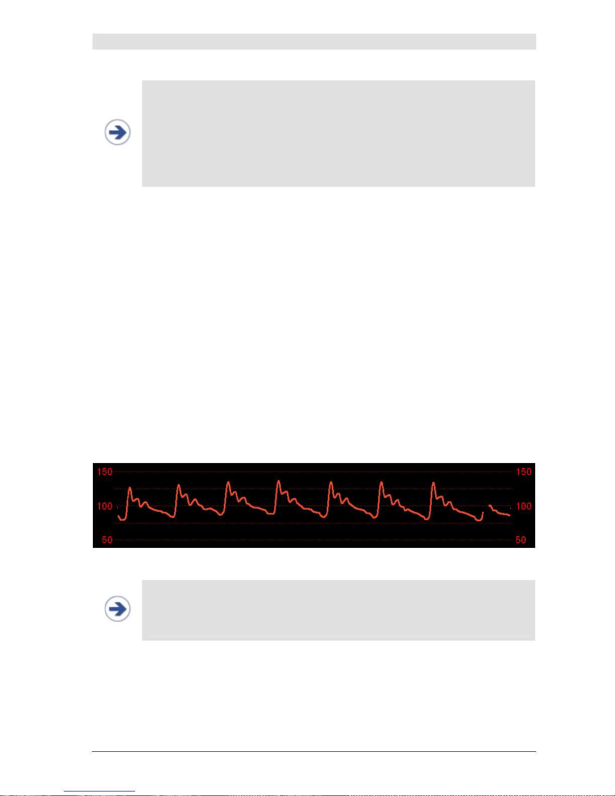
CNAP
TM
CNAP™ Monitor 500 Page 9-4 Version 3.5.1, PN: 21-FHZU-10002
NOTE:
• The
Start/Stop
key is primarily intended to stop the CNAP™ measurement and the
NBP measurement. In addition, the
Start/Stop
key serves to display the
Setup
Patient
dialog manually if it was not automatically displayed upon start of meas-
urement. After selecting a patient category in the
Setup Patient
dialog, the
CNAP™ measuring process starts automatically.
• A current NBP measurement can be stopped without interfering with a concurrently
performed CNAP™ measurement by pressing
Start/Stop
. Pressing the same key a
second time also stops the CNAP™ measurement.
9.4 View features
CNAP™ determines the following blood pressure values which are displayed directly in the Main Screen
of the CNAP™ Monitor 500:
• Blood pressure waveform (morphology)
• Blood pressure trends:
o Sys
o Dia
o Mean
o Pulse
• Numeric blood pressure values:
o Sys
o Dia
o Mean
o Pulse
9.4.1 Blood pressure waveform
The CNAP™ blood pressure waveform is displayed directly in the Main Screen.
Illustration 39: CNAP™ blood pressure waveform
NOTE:
• The mean and amplitude scales of the CNAP™ blood pressure waveform are set in
the
Trend
menu (see chapter 7 – Trends).
• The signal speed of the CNAP™ blood pressure waveform is set to 12.5 mm/sec and
cannot be adjusted in any way.
9.4.2 Trend view
The CNAP™ blood pressure trend is displayed in the
Trend frame
directly in the main screen of the
CNAP™ Monitor 500. It enables both graphic as well as a numeric view of blood pressure trends.
Page 63
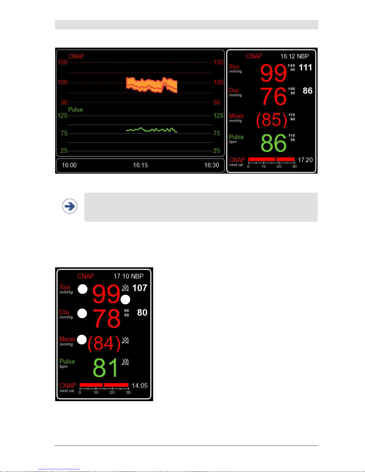
CNAP
TM
CNAP™ Monitor 500 Page 9-5 Version 3.5.1, PN: 21-FHZU-10002
Illustration 40: Graphic Trend and numeric values
NOTE:
• The mean and amplitude scales for CNAP™ trends, CNAP™ and pulse are set in the
Trend
menu (see chapter 7 – Trends).
9.4.3 Numeric values
The CNAP™
Parameter frame
displays the current blood pressure parameters
Sys, Mean, Dia
and
Pulse
:
Systolic blood pressure
Diastolic blood pressure
Mean blood pressure
Alarm limit settings
Illustration 41: Parameter frame
1
3
2
4
Page 64
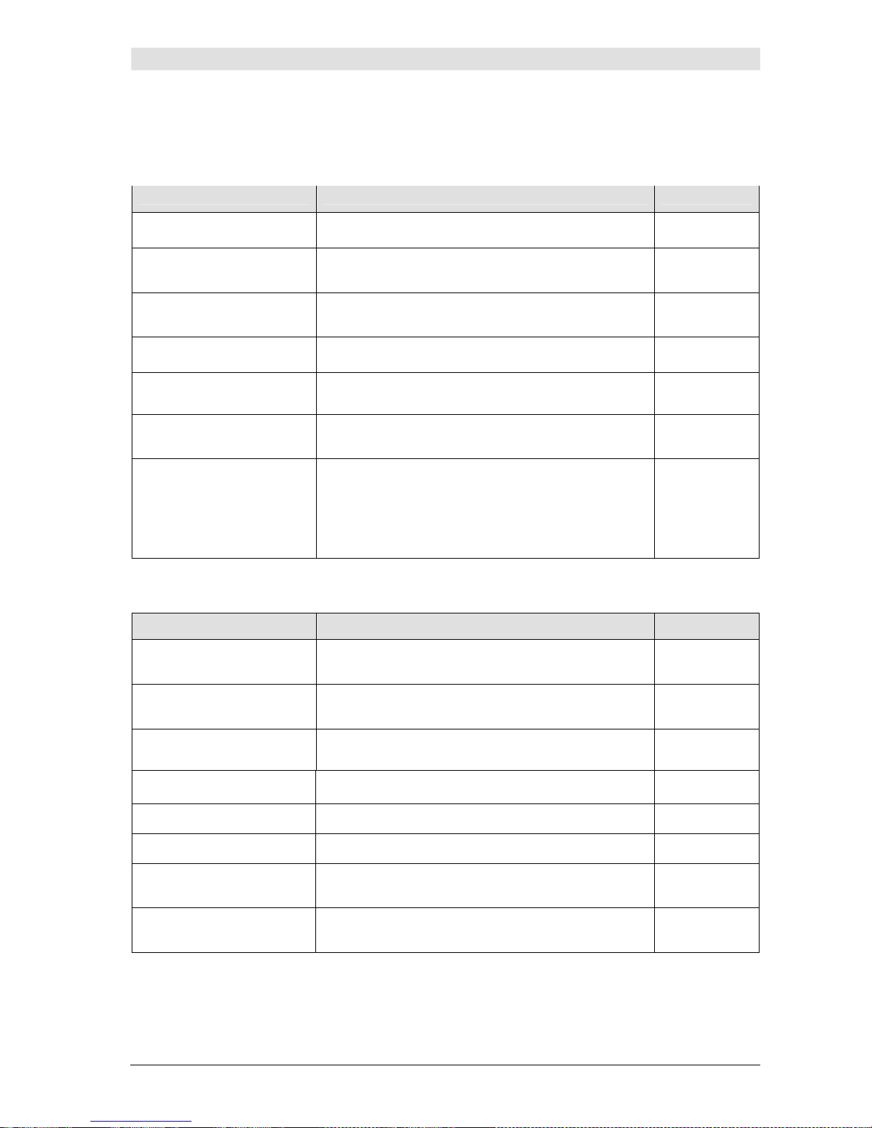
CNAP
TM
CNAP™ Monitor 500 Page 9-6 Version 3.5.1, PN: 21-FHZU-10002
9.5 CNAP™ options
Parameter
menu:
Menu item Description Settings
NBP: Start/Stop
Start/Stop of a single NBP measurement
NBP: Start/Stop Venous Stasis
Start/Stop of venous stasis
NBP: Interval
Setting of time interval for automatic NBP measurements [min]
Off, 5(5)30,
45, 60
CNAP: Change Finger
Change of signal source in CNAP™ double finger cuff
CNAP: Cal Interval
Setting of automatic change of signal source in
CNAP™ double finger cuff [min]
5(5)60 min
Pediatric/Adult
Alarm Limits…
Setting of alarms for the parameters Sys, Dia, Mean,
Pulse
Submenu
IBP: Zeroing Active
IBP: Zeroing
Start/Stop
Active zeroing for interface to external patient monitors before and after an active CNAP measurement
(available CNAP values).
Zeroing, which can be activated/deactivated manually, for interface to external patient monitors during
an active CNAP measurement.
Measurement
menu:
Menu item Description Settings
NBP: Mode
Automatic or manual NBP measurement at changes
of >=25 mmHg compared with the last NBP.
Auto,
Manual
NBP: Interval
Setting of time interval for automatic NBP measurements [min]
Off, 5(5)30,
45, 60
CNAP: Cal Interval
Setting of automatic change of signal source in
CNAP™ double finger cuff [min]
5(5)60 min
Audio Trend…
Setting of source and volume for audio trend Submenu
Display Options…
Submenu to adjust display settings Submenu
Print Options…
Submenu to set print options Submenu
Parameter Averaging
Averaging of display parameters
Off, 5, 10,
15
Patient Category
Presetting of the focus on Adult or Pediatric for new
patient setup
Adult, Pediatric
Page 65

CNAP
TM
CNAP™ Monitor 500 Page 9-7 Version 3.5.1, PN: 21-FHZU-10002
NOTE:
• Interruptions due to CNAP change of finger are displayed by means of red countdown
bars in the
Parameter frame
(see chapter 3.6 – Timer).
• Adjustments in the
Parameter
menu alter only the current measurement. In a new
measurement, they are transcribed by the defaults in the
Measurement
menu.
• Settings performed in the
Measurement
menu, however, alter both the current as
well as future measurements and are transcribed by factory settings upon reset.
Page 66
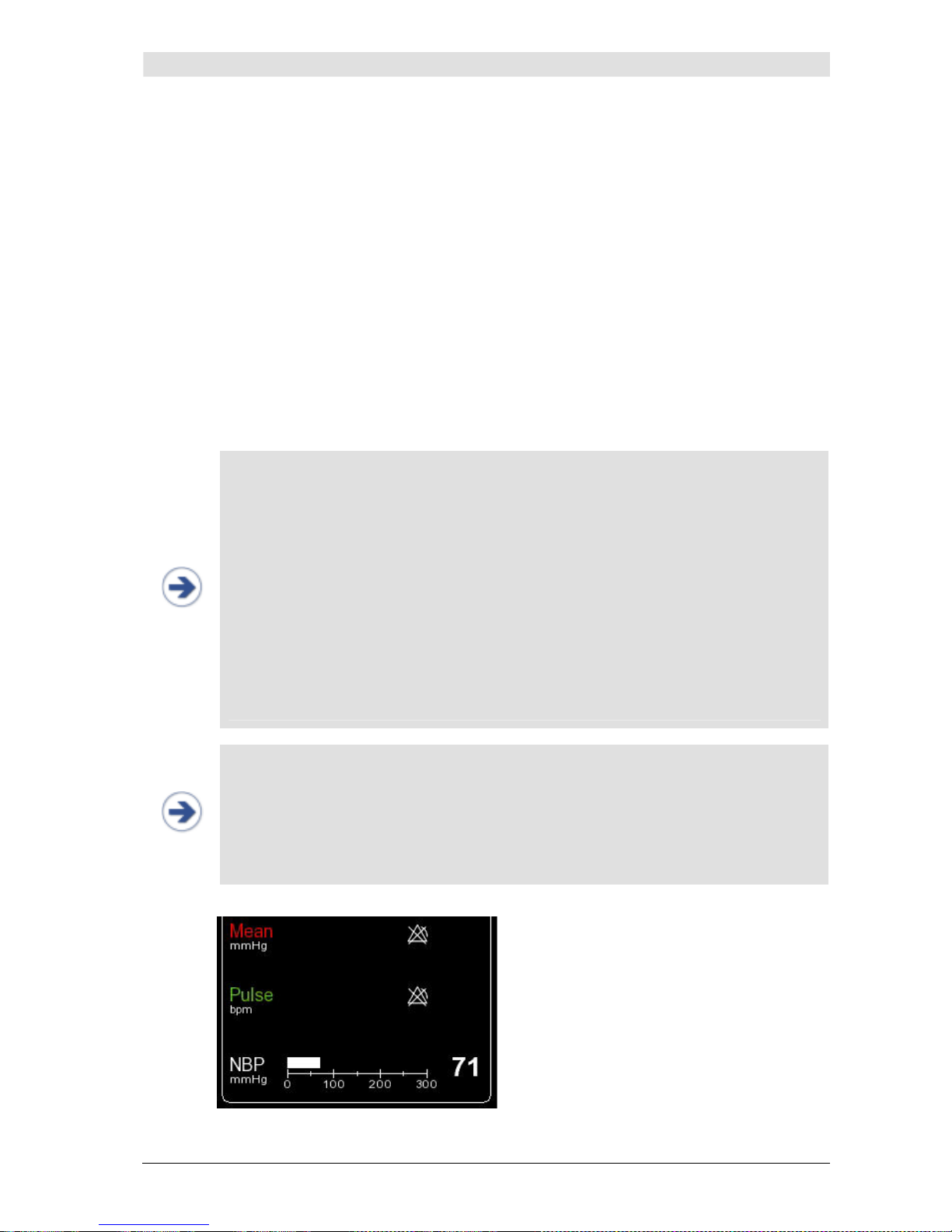
NBP
CNAP™ Monitor 500 Page 10-1 Version 3.5.1, PN: 21-FHZU-10002
10 NBP
General information.............................................................................................................10-1
Safety precautions............................................................................................................... 10-3
Setup ................................................................................................................................10-4
View features......................................................................................................................10-6
NBP options........................................................................................................................ 10-7
10.1 General information
NBP (Non-Invasive Blood Pressure) uses the oscillometric method to determine a patient's blood pressure on a non-continuous basis. To achieve this, the NBP module is integrated into the CNAP™ Monitor
500. Blood pressure measurement is conducted by means of a NBP cuff (available in 4 sizes) which is
placed around the patient's upper arm (brachial artery) and connected to the CNAP™ Monitor 500 on
the left side of the monitor (see chapter 3 – Introduction). For measurement purposes, the pressure in
the NBP cuff is controlled by the NBP module. The cuff pressure is first increased above systolic blood
pressure and decreased step by step. The pulsations in the NBP cuff provide the basis for deriving the
blood pressure values Sys and Dia.
NOTE:
• When a measurement process is started on the CNAP™ Monitor 500, a NBP meas-
urement is also triggered automatically.
• However, it is also possible to trigger an NBP measurement manually at any time
during measurement – except during display of the
Setup Patient
dialog (see
chapter 10.6 – NBP options).
• NBP measuring interval can be pre-set in the
Measurement
menu for every new
measurement and can be adapted via the
Parameter
menu during a measurement.
• Inflation pressure of the NBP cuff is determined by the selected patient category (see
chapter 5.1 – Patient entry). During NBP measurement, it is graphically and numerically displayed as a bar at the bottom of the
Parameter frame
(see illustration 42
below).
• Interruptions due to NBP measurements are displayed as white countdown bars in
the
Parameter frame
(see chapter 3.6 - Timer).
• During an NBP measurement, neither venous stasis nor manual change of finger can
be performed.
NOTE:
• The CNAP™ blood pressure waveform is calibrated by means of an oscillometric NBP
measurement. If the accuracy of the NBP measurement is affected by artifacts (e.g.
weak pulse, irregular pulse, artifacts from patient movement or tremor, or respiratory artifacts), this may also affect and reduce the accuracy of blood pressure values
measured by the CNAP™ Monitor 500.
• An NBP cuff can be put on the same arm as the CNAP™ double finger cuff (ipsilater-
ally) or on the other arm (contralaterally).
Illustration 42: NBP measurement
Page 67
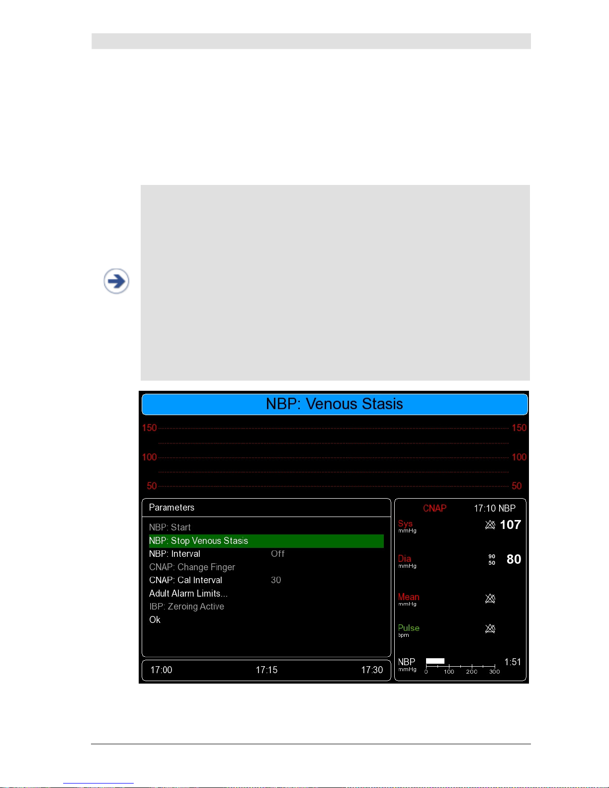
NBP
CNAP™ Monitor 500 Page 10-2 Version 3.5.1, PN: 21-FHZU-10002
10.2 Venous stasis
Venous stasis to support punctures of intravenous lines can be performed by means of the NBP cuff.
After putting on the NBP cuff, venous stasis can be started by selecting
NBP: Start Venous Stasis
in the
Parameter
menu at any time. During venous stasis, the
NBP: Start Venous Stasis
status message is displayed (see illustration below). Depending on the selected patient category, the NBP
cuff is inflated to constant pressure levels of 80mmHg for adults and 60mmHg for pediatric patients.
NOTE:
• During venous stasis, the cuff inflation pressure is graphically displayed as a bar at
the bottom of the
Parameter frame
(analogous to the NBP measurement, see
chapter 10.1 – General information).
• Until the target pressure of 80/60mmHg is reached, the pressure is displayed nu-
merically to the right of the bar.
• After the target pressure has been reached, the numeric display of pressure is re-
placed by the time remaining until automatic stop of venous stasis (see illustration 43
below).
• Venous stasis can be performed for max. 2 minutes. If venous stasis is not termi-
nated prematurely by selecting
NBP: Stop Venous Stasis
manually, it will stop
automatically after 2 minutes. In case it was performed during an ongoing CNAP
measurement, it will be continued afterwards automatically.
• Numeric display of continuous blood pressure is not available during venous stasis;
however, the blood pressure waveform will continue to be displayed (without scale).
• Venous stasis cannot be performed while the
Setup Patient
dialog is displayed.
• Neither manual NBP nor manual change of finger can be performed during venous
stasis.
Illustration 43: Venous stasis
Page 68

NBP
CNAP™ Monitor 500 Page 10-3 Version 3.5.1, PN: 21-FHZU-10002
10.3 Safety precautions
STOP:
• Patient category: Make sure to select the correct patient category before starting a
measurement (see chapter 5.1 – Patient entry). The higher adult levels of inflation
pressure of the NBP cuff, excess pressure limits or measuring time for instance, must
never be used for pediatric patients!
• Intravenous infusion lines: Never put on an NBP cuff to a limb already connected
to an intravenous infusion line or an intra-arterial catheter. The inflation of the cuff
might result in the infusion solution being caught up or even cause tissue damage to
the punctured area.
• Cutaneous lesions: Never perform NBP measurements in patients suffering from
drepanocythemia or from cutaneous lesions, or in patients where cutaneous lesions
are to be expected.
• Unsupervised measurements: Patients with severe blood coagulation dysfunction
may develop haematoma on the limb where the NBP cuff has been inflated. In these
cases, carefully consider the pros/cons of frequent unsupervised blood pressure measurements.
• Interference by external devices: Results of NBP recordings are not to be used if
the measured oscillometric pulse has been influenced by other devices or techniques
(e.g. contrapulsation).
• Interpretation: NBP recordings are to be interpreted only by a physician or medical
professional staff.
• Limitations of NBP measurements: NBP recordings may be inaccurate or even
impossible under the following conditions:
o lack of detectable regular arterial blood pressure,
o arrhythmia,
o strong and persistent patient movement (e.g. tremor or convulsions),
o rapid blood pressure fluctuations,
o severe shock or hypothermia with reduced peripheral blood flow,
o obesity, as adipose tissue in the limbs muffles arterial oscillations.
NOTE:
• In order to ensure the accuracy of NBP measurements, be sure to choose the right
size of the upper arm cuff. Selecting the wrong size or incorrect attaching of the cuff
may cause significant inaccuracies of recordings!
• In case of longer monitoring, be sure to inspect the correct blood supply of the pa-
tient's limbs on a regular basis.
• The NBP cuff is made of latex free and skin-friendly synthetic material.
Page 69
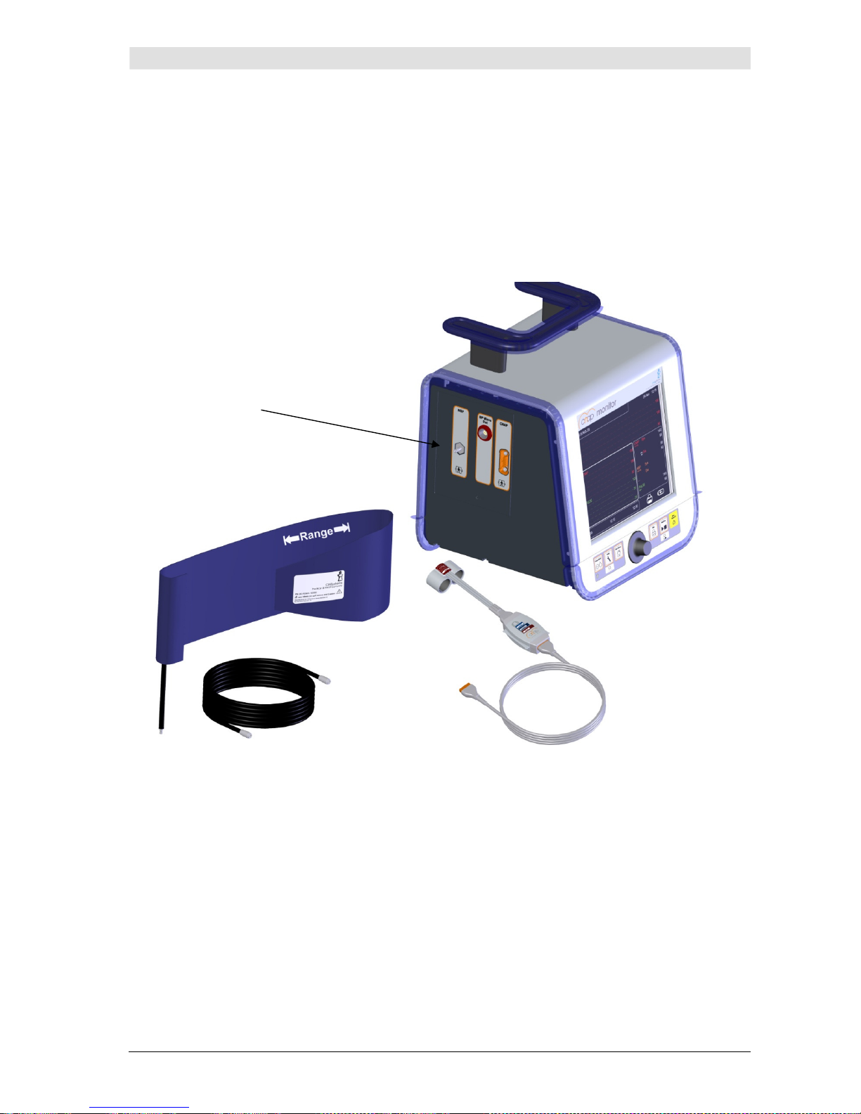
NBP
CNAP™ Monitor 500 Page 10-4 Version 3.5.1, PN: 21-FHZU-10002
10.4 Setup
The NBP hardware consists of the following components:
• NBP cuff (Child, Small adult, Adult, Large adult)
• NBP module (integrated into the CNAP™ Monitor 500)
• NBP air connector
Illustration 44: CNAP™ Monitor 500 with NBP air connector
NBP air connector
Page 70
NBP
CNAP™ Monitor 500 Page 10-5 Version 3.5.1, PN: 21-FHZU-10002
Start/Stop a measurement:
1. Make sure you are using an NBP cuff authorized by CNSystems and make sure to use the correct
size.
NOTE:
• The width of the cuff should be between 37% and 47% of the circumference of the
patient's limb. The inflatable part of the cuff should be at least 80% of the respective
extremity.
• The following NBP cuff sizes are available:
Size Arm circumference (cm)
Child 12 - 19
Small Adult 17 - 25
Adult 23 - 33
Large Adult 31 - 40
2. Attach the NBP cuff on the upper arm of the patient at heart level. The marker on the NBP cuff
should be directly above the brachial artery.
NOTE:
Do not attach the cuff too tightly around the limb as this might cause problems during
inflation and deflation of the cuff and lead to ischemia of the extremities. Be sure to
inspect the patient's skin (color, temperature, sensitivity of limb) around the cuff on a
regular basis. Should any signs of alterations to the skin or decreased blood supply be
noticeable, immediately change arm or stop the blood pressure measurement altogether.
3. Connect the NBP cuff with the NBP air connector on the left side of the CNAP™ Monitor 500.
4. There are 2 ways to start an NBP measurement:
a) The start of a CNAP™ measurement also automatically starts an NBP measurement. NBP
measurements are performed after the calibration phase of the CNAP™ Monitor 500 or
automatically in defined time intervals. To set the desired time intervals, access either the
Parameter
menu or the
Measurement
menu.
b) Starting a single measurement by using the click-wheel control to access the
Parame-
ter
menu.
NOTE:
The NBP measurement serves to calibrate the CNAP™ blood pressure measurement at
the height of the heart.
Page 71
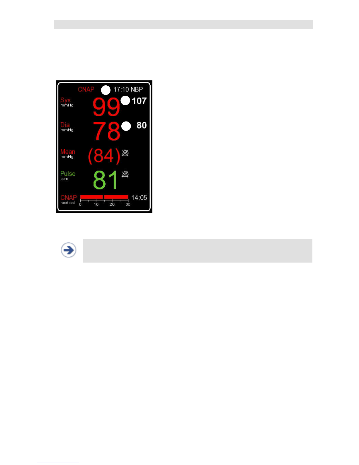
NBP
CNAP™ Monitor 500 Page 10-6 Version 3.5.1, PN: 21-FHZU-10002
10.5 View features
By means of NBP, the blood pressure values
Sys
and
Dia
are determined and displayed in the
Pa-
rameter frame
of the CNAP™ Monitor 500.
Systolic blood pressure
Diastolic blood pressure
Time of last NBP measurement
Illustration 45: Parameter frame
NOTE:
The
Parameter frame
always displays the most recent NBP values as well as the
time of measurement.
1
3
2
Page 72
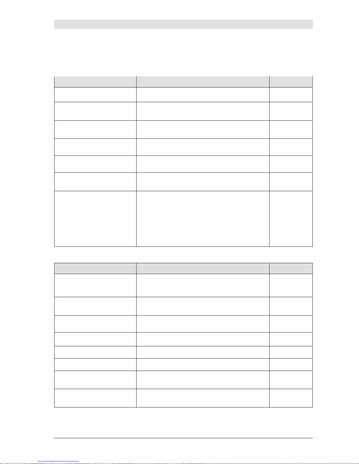
NBP
CNAP™ Monitor 500 Page 10-7 Version 3.5.1, PN: 21-FHZU-10002
10.6 NBP options
Parameter
menu:
Menu item Description Settings
NBP: Start/Stop
Start/Stop of a single NBP measurement
NBP: Start/Stop Venous
Stasis
Start/Stop venous stasis
NBP: Interval
Setting of time interval for automatic NBP measurements [min]
Off, 5(5)30,
45, 60
CNAP: Change Finger
Change of signal source in CNAP™ double finger
cuff
CNAP: Cal Interval
Setting of automatic change of signal source in
CNAP™ double finger cuff [min]
5(5)60
Pediatric/Adult
Alarm Limits…
Setting of alarms for the parameters Sys, Dia,
Mean, Pulse
Submenu
IBP: Zeroing Active
IBP: Zeroing Start/Stop
Active zeroing for interface to external patient
monitors before and after an active CNAP™ measurement (available CNAP values).
Zeroing, which can be activated/deactivated manually, for interface to external patient monitors
during an active CNAP measurement.
Measurement
menu:
Menu item Description Settings
NBP: Mode
Automatic or manual NBP measurement at
changes of ≥ 25 mmHg compared with the last
NBP.
Auto,
Manual
NBP: Interval
Setting of time interval for automatic NBP measurements [min]
Off, 5(5)30,
45, 60
CNAP: Cal Interval
Setting of automatic change of signal source in
CNAP™ double finger cuff [min]
5(5)60
Audio Trend…
Setting of source and volume for audio trend Submenu
Display Options…
Submenu to adjust display settings Submenu
Print Options…
Submenu to set print options Submenu
Parameter Averaging
Averaging of display parameters
Off, 5, 10,
15
Patient Category
Presetting of the focus on Adult or Pediatric for
new patient setup
Adult,
Pediatric
Page 73

NBP
CNAP™ Monitor 500 Page 10-8 Version 3.5.1, PN: 21-FHZU-10002
NOTE:
• Adjustments in the
Parameter
menu alter only the current measurement and are
transcribed by defaults
in the
Measurement
menu when a new measurement is
started.
• Settings performed in the Measurement menu, however, alter both the current as
well as future measurements and can be transcribed by the operator or factory settings from the Service menu.
Page 74
Cleaning and disinfection
CNAP™ Monitor 500 Page 11-1 Version 3.5.1, PN: 21-FHZU-10002
11 Cleaning and disinfection
General precautions.............................................................................................................11-1
Cleaning............................................................................................................................. 11-1
Disinfection ........................................................................................................................11-2
Only use disinfectants and detergents recommended by CNSystems Medizintechnik AG to clean or
disinfect the device and its accessories. CNSystems’ warranty does not cover any damage caused by
the use of unsuitable cleaning agents or methods.
The warranty of CNSystems does not apply to the effectiveness of the mentioned cleaning agents and
methods for the purpose of infection prevention and control. When in doubt, the operator should contact the hospital hygiene department. This particularly applies for the effectiveness of disinfectants
and detergents against hepatitis B and HI viruses. The operator is to follow the regulations of the respective hospital and country.
11.1 General precautions
The CNAP™ Monitor 500 including all its components and accessories are to be kept clean and free of
dust. After cleaning and disinfecting the devices, they must be thoroughly inspected before use. If any
components show signs of wear or damage, these components must not be used for patient measurements! Before sending devices and components back to CNSystems Medizintechnik AG, they are to
be decontaminated.
CAUTION:
• Always dilute detergents according to manufacturers' instruction, or use in the small-
est possible concentration.
• No liquid must ingress the CNAP™ Monitor 500.
• Do not dip instruments, device parts or components in liquid.
• Do not pour any liquid directly on the device.
• Do not let residues of detergents or disinfectants air-dry on any parts of the device.
Wipe them off with a cloth moist with water, then dry the instruments with a clean
cloth.
• Never use scouring agents or abrasive detergents (e.g. steel wool or silver polish).
• Do not use bleaching agents!
• Wipe off detergents and disinfectants with a moist cloth (water), then dry surfaces
with a clean cloth.
STOP:
No liquid must be spilt on any part of the CNAP™ Monitor 500. In case this should happen, carefully dry device/accessory. If in doubt whether liquid has ingressed the device,
do not start up the instrument. Contact technical staff or a service partner of CNSystems
Medizintechnik AG.
11.2 Cleaning
In order to clean any part of the device use a lint-free cloth, moist with warm water (max. 40° C), and
soap, diluted non-caustic detergents, tensides or detergents containing ammonia or alcohol. Do not
use strong solvents like dimethylketone or trichloroethylene. Do not dip the device, any part of the
device or any accessories (especially not the hoses) into liquid.
As the screen of the CNAP™ Monitor 500 is easily scratched, be particularly careful when cleaning it.
No liquid must enter the CNAP™ Monitor 500, so be sure to not spill any liquid directly on the monitor.
No liquid must enter the connectors of the CNAP™ Monitor 500 or the CNAP™ controller, so take care
not to wipe over, but rather around the connectors when cleaning them.
Page 75

Cleaning and disinfection
CNAP™ Monitor 500 Page 11-2 Version 3.5.1, PN: 21-FHZU-10002
CAUTION:
Be particularly careful when cleaning or disinfecting the insides of the CNAP™ double
finger cuffs. Wipe them carefully in order to avoid any damage.
11.3 Disinfection
CAUTION:
Disinfectant agents: Never mix different kinds of disinfecting solutions (e.g. bleaching
agents and ammonia), as this might result in the production of dangerous gases!
Internal hospital regulations: Disinfect the product in accordance with your own hospital regulations in order to avoid long-term damage of any kind.
The device is to be cleaned before disinfection. Find recommended disinfectants listed below:
Desinfektionsmittel Konzentration
Glutaraldehyd 3.4%
n-Alkyl/Alkohol 0.28% - 8%
Hypo-chlorite 0,55%
Succindial-dehyd/
Alkohol
11%
Alkohol Spray/ Wipe 10%
Orthophthal-aldehyd 0,55%
Propan-1-ol < 50%
Propan-2-ol < 50%
Common brands:
• Cidex® Plus
• Theracide®
• Gigasept® FF
• Cidex® OPA
• Schülke - Microcid® AF Liquid
• ECOLAB - Indicidin® Liquid
• B.Braun – Meliseptol®
• BODE – Bacillol® plus
Page 76
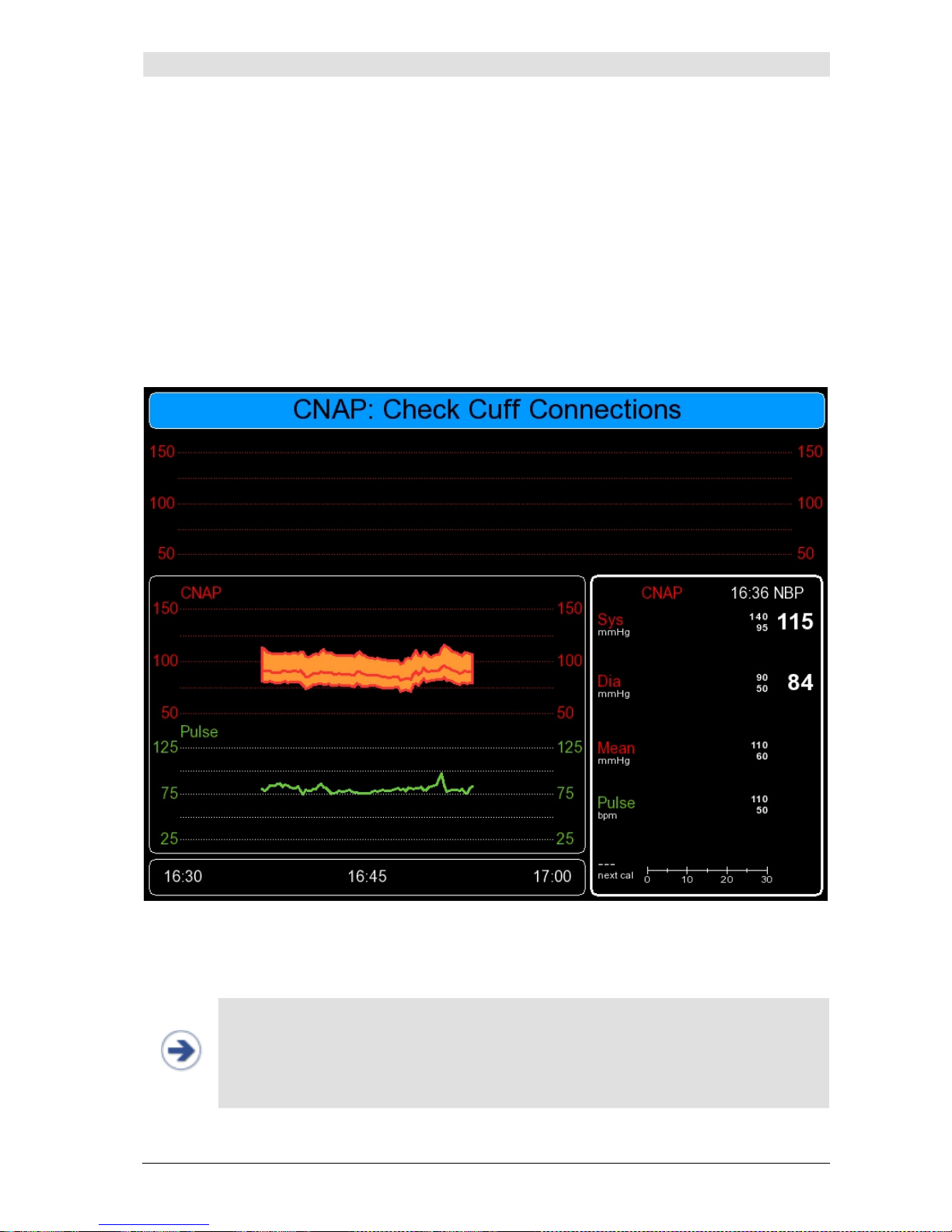
Technical alarms and status messages
CNAP™ Monitor 500 Page 12-1 Version 3.5.1, PN: 21-FHZU-10002
12 Technical alarms and status messages
Main Unit – Status messages ................................................................................................12-2
Main Unit - Technical alarms.................................................................................................12-2
BP Wave Out (IBP) - Status messages ...................................................................................12-3
BP Wave Out (IBP) - Technical alarms ...................................................................................12-3
Printer - Technical alarms.....................................................................................................12-4
CNAP™ - Status messages ...................................................................................................12-4
CNAP™ - Technical alarms....................................................................................................12-5
NBP – Status messages........................................................................................................12-8
NBP – Technical alarms........................................................................................................ 12-9
Besides physiological alarms, the CNAP™ Monitor 500 displays technical malfunction alarms (white)
and device status messages (blue) in the
Alarm frame
.
Illustration 46: Status messages
The following documentation lists all technical alarms and device status messages that may occur
during the use of the CNAP™ Monitor 500.
NOTE:
• In case you require service support for your CNAP™ Monitor 500, please report the
exact technical alarm to the service partner.
• A complete list of technical alarms including error code, time and date of appearance
is available from the Log menu located in the
Service
menu. You will find the pass-
word for the service menu in the CNAP™ Monitor 500 "Service manual for users".
Page 77
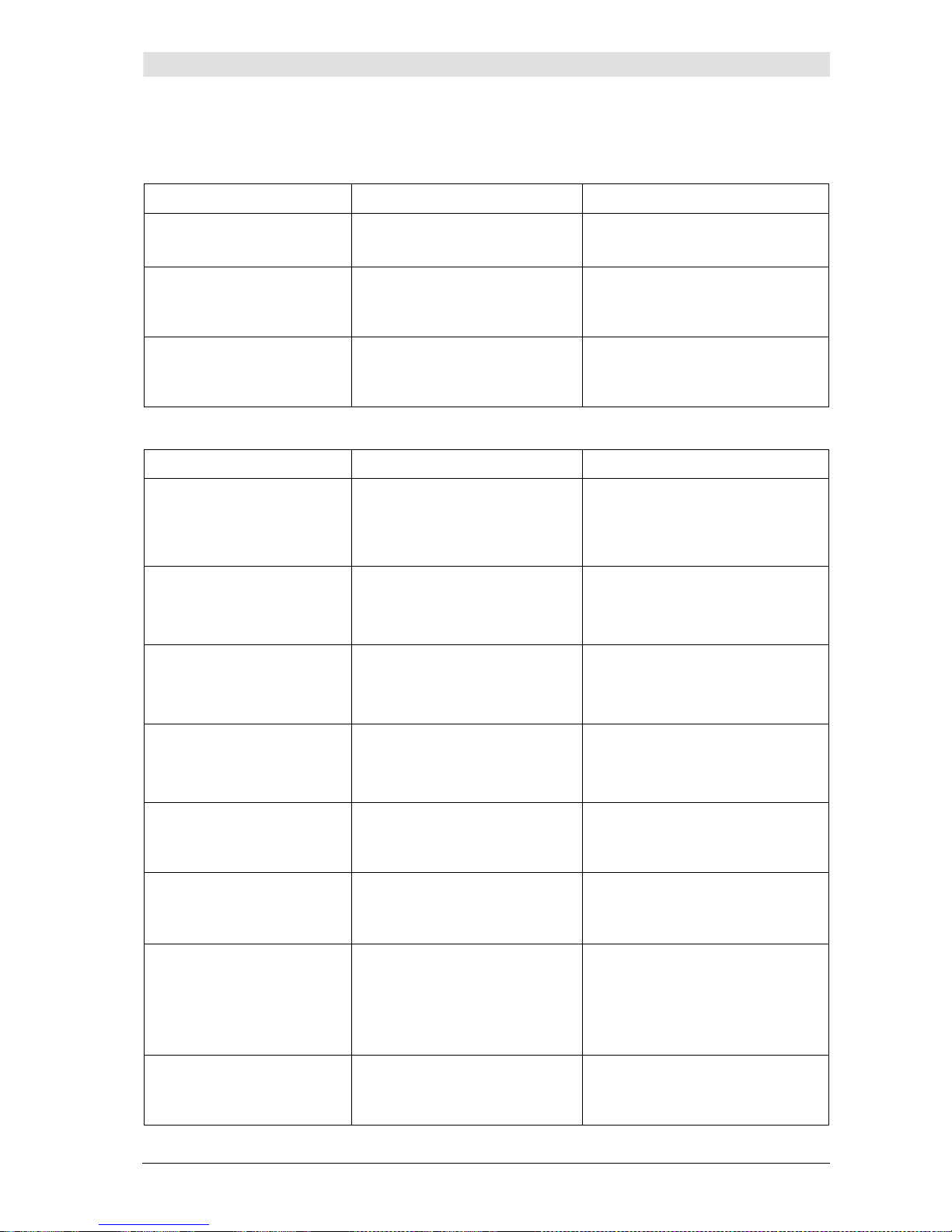
Technical alarms and status messages
CNAP™ Monitor 500 Page 12-2 Version 3.5.1, PN: 21-FHZU-10002
12.1 Main unit
12.1.1 Status messages
Message Possible cause Measures
MU: No USB Stick
Attached
- No USB stick connected
- Connect USB stick and reboot
CNAP™ Monitor 500
MU: USB Stick Full
- USB memory full
- Connect USB with free storage
capacity and reboot CNAP™
Monitor 500
MU: USB Stick Write
Error
- USB stick not recognized
- Activate and deactivate the
Record setting in Setup. Use
compatible USB stick.
12.1.2 Technical alarms
Message Possible cause Measures
MU: Fatal Error –
Contact Service
- Internal error; CNAP™ moni-
tor must not be used for further measurements
- Reboot CNAP™ Monitor 500
- In case of persistent error, con-
tact service
MU: CNAP Failure
- Failure in CNAP™hardware
- Reboot CNAP™ Monitor 500
- In case of persistent error, con-
tact service
MU: NBP Failure
- Failure in NBP hardware
- Reboot CNAP™ Monitor 500
- In case of persistent error, con-
tact service
MU: IBP Failure
- Failure in IBP component
- Reboot CNAP™ Monitor 500
- In case of persistent error, con-
tact service
MU: Battery: Low
- Very low battery charge sta-
tus (< 25%), battery operation still possible
- Switching to mains operation
via power adapter recommended
MU: Battery: Depleted
- Battery depleted, operation
possible for 15 minutes at
most
- Immediately switch to mains
operation via power adapter
MU: Battery: Shutdown
- Battery depleted, operation
possible for 5 minutes at
most; monitor is switched off
- Immediately switch to mains
operation via power adapter
- Current measurement discon-
tinued, monitor switched off automatically
MU: Memory Full –
Discharge Patient
- Internal memory is full (as a
result of long measuring periods without discharging)
- Discharge patient
- Start new measurement
Page 78
Technical alarms and status messages
CNAP™ Monitor 500 Page 12-3 Version 3.5.1, PN: 21-FHZU-10002
12.2 BP Wave Out (IBP)
12.2.1 Status messages
Message Possible cause Measures
IBP: Connected
- BP Wave Out is connected
to patient monitor
- Perform zeroing (refer to chap-
ter 4.4)
- Make sure to disable zeroing
when calibration is complete
IBP:
Disconnected
- BP Wave Out is discon-
nected from patient monitor
- n.a.
12.2.2 Technical alarms
Message Possible cause Measures
IBP: Fault
- Internal controller problem
- Reboot CNAP™ Monitor 500
- In case of persistent error, con-
tact service
IBP:
Transmission Fault
- Interface problem
- In case of persistent error, con-
tact service
IBP:
EEPROM RW Error
- I/O memory chip defective
- Reboot CNAP™ Monitor 500
- In case of persistent error, con-
tact service
IBP:
Iso Board Fault
- Isolation board failure
- In case of persistent error, con-
tact service
IBP: Iso Board
Bridge Voltage
- Bridge voltage > 10V (BP
Wave Out)
- Disconnect CNAP™ transducer
cable
- Check bridge voltage range of
patient monitor (refer to chapter 4.4)
- In case of persistent error, con-
tact service
Page 79

Technical alarms and status messages
CNAP™ Monitor 500 Page 12-4 Version 3.5.1, PN: 21-FHZU-10002
12.3 Printer
12.3.1 Technical alarms
Message Possible cause Measures
PRINTER: Out of Paper
- Printer is out of
paper
- Replenish paper
PRINTER: Fault
- Hardware problem:
o Excess tempera-
ture
o Internal voltage
supply error
- Problem will be solved automati-
cally
- In case of persistent error, con-
tact service
PRINTER: Failure
- Hardware problem
- Interface problem
- Contact service
PRINTER:
Communication Error
- Interface problem
- Problem will be solved automati-
cally
- In case of persistent error, con-
tact service
12.4 CNAP™
12.4.1 Status messages
Message Possible cause Measures
CNAP:
Check Connections
- CNAP™ controller is
not connected
- Check connection of CNAP™ con-
troller
CNAP: Check Cuff Connections
- CNAP™ double finger
cuff is not connected
- Check connection of CNAP™ dou-
ble finger cuff
CNAP: Check Cuff
- No finger in inactive
cuff (before CNAP:
Change Finger)
- Put finger in CNAP™ finger cuff
CNAP: Initializing…
- System self-test - n.a.
CNAP:
Controller Not Calibrated
- CNAP™ controller is
not calibrated
- Replace CNAP™ controller
- Contact service (CNAP™ control-
ler)
CNAP: Put Fingers in Cuff
- CNAP™ self-test suc-
cessful; CNAP™ is
ready for patient setup and measurement
- Patient setup
CNAP: Calibration…
- CNAP™ calibration
phase in progress
- Wait for end of calibration
Page 80

Technical alarms and status messages
CNAP™ Monitor 500 Page 12-5 Version 3.5.1, PN: 21-FHZU-10002
Message Possible cause Measures
CNAP: Calibrating NBP
- NBP measurement to
calibrate CNAP™
blood pressure is in
progress
- Wait for end of NBP measurement
CNAP: Artefact
- CNAP™ blood pres-
sure is not within
physiological measuring range
- Low signal amplitude
in CNAP™ double finger cuff
- Interference because
of third party measuring devices
- CNAP™ hardware is
ringing due to artifacts
- Check and eliminate influence
from third party measuring devices
- Avoid artifacts (e.g. movements)
- Check CNAP™ cables and connec-
tors
- Check CNAP™ double finger cuff
- Replace CNAP™ double finger cuff
and cable
CNAP:
Cuff Expiring
- CNAP™ cuff is reach-
ing end of lifecycle,
thus providing low
quality of measurement
- Replace CNAP™ double finger cuff
CNAP: Cuff Ambient Light
- Ambient light inter-
feres with CNAP™
double finger cuff
- Reduce ambient light (i.e. bright-
ness, switch off, …)
- Check setup of CNAP™ double
finger cuff
12.4.2 Technical alarms
Message Possible cause Measures
CNAP: Fault –
Reservoir Pressure
- Air reservoir blocked
or faulty pressure offset
- Disconnect and reconnect
CNAP™ controller
- In case of persistent error, con-
tact service
CNAP: Fault –
Zero Offset Controller
- Zero offset of CNAP™
controller faulty
- In case of persistent error, con-
tact service for faulty CNAP™
controller
CNAP: Fault – Initial Pressure
- Pressure could not
reach threshold upon
initialization
- Check CNAP™ cables and con-
nectors
- In case of persistent error, con-
tact service
CNAP: Fault –
Pump/Tubing/Valve
Leaky
- Leakage detected
upon initialization
- Check CNAP™ cables and con-
nectors
Page 81

Technical alarms and status messages
CNAP™ Monitor 500 Page 12-6 Version 3.5.1, PN: 21-FHZU-10002
Message Possible cause Measures
- In case of persistent error, con-
tact service
CNAP: Failure – Valve
Blocked/Leaky
- Valve blocked or leaky
- Disconnect CNAP™ hardware
- In case of persistent error, con-
tact service for faulty CNAP™
controller
CNAP: Failure –
Reservoir Overpressure
- Pressure exceeded
450mmHg for more
than 10 sec in CNAP™
air reservoir
- Disconnect CNAP™ hardware
- Reboot CNAP™ monitor
- In case of persistent error, con-
tact service
CNAP: Failure –
Cuff Overpressure Left
- Pressure exceeded
330mmHg for more
than 10 sec in left
CNAP™ finger cuff
- Disconnect CNAP™ hardware
- Reboot CNAP™ monitor
- In case of persistent error, con-
tact service
CNAP: Failure –
Cuff Overpressure Right
- Pressure exceeded
330mmHg for more
than 10 sec in right
CNAP™ finger cuff
- Disconnect CNAP™ hardware
- Reboot CNAP™ monitor
- In case of persistent error, con-
tact service
CNAP: Cuff Cannot
Deflate/Blocked
- CNAP™ finger cuff
cannot be deflated
- Replace CNAP™ double finger
cuff
- In case of persistent error, con-
tact service
CNAP: Check Cuff –
Low Light Signal
- Low light signal in
CNAP™ finger cuff (PI
too low)
- Check patient for low peripheral
blood flow
- Check size of CNAP™ double
finger cuff
- Check setup of CNAP™ double
finger cuff
- Check proper optical path in
CNAP™ double finger cuff
CNAP:
Check Cuff –
Ambient Light
- Ambient light inter-
feres with CNAP™
double finger cuff
- Reduce ambient light
- Check setup of CNAP™ double
finger cuff
CNAP:
Check Cuff –
Timeout On Calibration
- Missing NBP calibra-
tion
- Signal quality insuffi-
cient during the calibration cycle (max.
5min)
- Check NBP for proper setup and
measurement
- Check size of CNAP™ double
finger cuff
- Check setup of CNAP™ double
finger cuff
Page 82

Technical alarms and status messages
CNAP™ Monitor 500 Page 12-7 Version 3.5.1, PN: 21-FHZU-10002
Message Possible cause Measures
- Improve peripheral blood flow
(e.g. warm patient’s hand)
CNAP: Cuff Fault –
Overpressure
- Pressure exceeded
330mmHg for more
than 2 sec in CNAP™
finger cuff
- Check CNAP™ double finger cuff
for patient movement
- Disconnect and reconnect
CNAP™ hardware
- In case of persistent error, con-
tact service
CNAP: Cuff Fault –
Light Sensor Left
- Light sensor in left
CNAP™ finger cuff defective
- Check proper optical path in
CNAP™ double finger cuff
- Check influence from ambient
light
- In case of persistent error, re-
place CNAP™ double finger cuff
CNAP: Cuff Fault –
Light Sensor Right
- Light sensor in right
CNAP™ finger cuff defective
- Check proper optical path in
CNAP™ double finger cuff
- Check influence from ambient
light
- In case of persistent error, re-
place CNAP™ double finger cuff
CNAP: Cuff Fault –
Memory
- Memory chip in
CNAP™ double finger
cuff defective
- Replace CNAP™ double finger
cuff
CNAP: Cuff Fault –
Unlicensed
- CNAP™ double finger
cuff is not licensed for
CNAP™ Monitor 500
- Check for permutation with
equipment from third party devices
CNAP: Cuff Fault –
Safety Shutdown
- CNAP™ cuff has
reached end of lifecycle, thus providing low
quality of measurement – it must be replaced immediately
- Replace CNAP™ double finger
cuff immediately
- Order new CNAP™ double finger
cuff in corresponding size
CNAP: Cuff Fault –
Leakage Left
- Leakage in left CNAP™
finger cuff
- Check connections of CNAP™
hardware
- Replace CNAP™ double finger
cuff (check with other cuff size)
- In case of persistent error, re-
place CNAP™ double finger cuff
Page 83

Technical alarms and status messages
CNAP™ Monitor 500 Page 12-8 Version 3.5.1, PN: 21-FHZU-10002
Message Possible cause Measures
CNAP: Cuff Fault –
Leakage Right
- Leakage in right
CNAP™ finger cuff
- Check connections of CNAP™
hardware
- Replace CNAP™ double finger
cuff (check with other cuff size)
- In case of persistent error, re-
place CNAP™ double finger cuff
CNAP: Cuff Failure –
Inflation Timeout
- Inflation of CNAP™
finger cuff exceeded
time limit
- Disconnect CNAP™ hardware
- Reboot CNAP™ monitor
- In case of persistent error, con-
tact service
CNAP: Controller Fault –
Memory
- Memory chip in
CNAP™ controller defective
- Disconnect and reconnect
CNAP™ controller
- In case of persistent error, con-
tact service for faulty CNAP™
controller
CNAP: Controller Fault –
Unlicensed
- CNAP™ controller is
not licensed for
CNAP™ Monitor 500
- Check for permutation with
equipment from third party devices
12.5 NBP
12.5.1 Status messages
Message Possible cause Measures
NBP: Terminated
- User has stopped cur-
rent NBP measurement
- n.a.
NBP: Fault
- Checksum error oc-
curred
- Start new NBP measurement
- In case of persistent error, con-
tact service
NBP: Single Measurement
- User has triggered a
single NBP measurement
- n.a.
NBP: Automatic Measurement
- Timed NBP measure-
ment (NBP: Interval)
- n.a.
NBP:
Checking CNAP
- NBP check measure-
ment as CNAP™ blood
pressure changed
more than 25mmHg
within one minute
(compared with last
NBP measurement)
- n.a.
Page 84

Technical alarms and status messages
CNAP™ Monitor 500 Page 12-9 Version 3.5.1, PN: 21-FHZU-10002
Message Possible cause Measures
NBP: Venous Stasis
- Venous stasis is per-
formed
- n.a.
12.5.2 Technical alarms
Message Possible cause Measures
NBP:
Weak Or No Signal
- Weak or no oscil-
lometric signal
- Check position and fit of NBP
cuff
- Make sure cuff is placed directly
on the skin
NBP: Artefact
- Artifact/irregular oscil-
lometric signal
- Check position and fit of NBP
cuff
- Avoid artifacts (e.g. movement)
- Check for proper NBP cuff size
- Check ECG for sinus rhythm
NBP:
Exceeded Retry Count
- In spite of numerous
retries, no measurement possible
- Avoid artifacts (e.g. movement)
- Check position and fit of NBP
cuff
- Make sure cuff is placed directly
on the skin
- Check for proper NBP cuff size
NBP:
Measurement Timeout
- Time limit for meas-
urement has been exceeded
- Avoid artifacts (e.g. movement)
- Check position and fit of NBP
cuff
- Make sure cuff is placed directly
on the skin
- Check for proper NBP cuff size
Page 85

Technical alarms and status messages
CNAP™ Monitor 500 Page 12-10 Version 3.5.1, PN: 21-FHZU-10002
Message Possible cause Measures
NBP:
Blocked Line
- Blocked line / air hose
- Make sure that NBP air hose is
not bent, or twisted too tight
- Make sure patient is not lying
on NBP cuff or air hose
- Check position and fit of NBP
cuff
NBP: Leakage
- NBP cuff or air hose
leaking or loose
- Check NBP air connections (e.g.
for damages, loose fit)
- Check NBP cuff for leakage
- Check position and fit of NBP
cuff
- Check for proper NBP cuff size
NBP:
Safety Timeout
- Safety time limit ex-
ceeded
- Check position and fit of NBP
cuff
- Avoid artifacts (e.g. movement)
- Check for proper NBP cuff size
- Start new NBP measurement
NBP: Overpressure
- Overpressure in NBP
cuff
- Check for proper NBP cuff size
- Make sure NBP air hose is not
bent, or twisted too tight
- Check position and fit of NBP
cuff
- Make sure patient is not lying
on NBP cuff or air hose
NBP: Hardware Fault
- Voltage supply ex-
ceeds limits or other
hardware problem
- Reboot CNAP™ Monitor 500
- In case of persistent error, con-
tact service
Page 86

Technical alarms and status messages
CNAP™ Monitor 500 Page 12-11 Version 3.5.1, PN: 21-FHZU-10002
Message Possible cause Measures
NBP:
Autozero Failure
- Autozeroing has failed
- Reboot CNAP™ Monitor 500
- In case of persistent error, con-
tact service
NBP:
Out Of Range Failure
- Measuring transducer
out of measuring
range
- Reboot CNAP™ Monitor 500
- In case of persistent error, con-
tact service
NBP: ADC Failure
- Analog/digital con-
verter out of measuring range
- Reboot CNAP™ Monitor 500
- In case of persistent error, con-
tact service
NBP: Calibration Failure
- Faulty EEPROM cali-
bration data
- Reboot CNAP™ Monitor 500
- In case of persistent error, con-
tact service
Page 87

Appendix A
CNAP™ Monitor 500 Page 13-1 Version 3.5.1, PN: 21-FHZU-10002
13 Appendix A – Glossary
A
AC Alternating current
Ah Ampere-hour
B
BP Wave Out Interface to patient monitors (CNAP
TM
blood pressure waveform)
bpm Beats per minute
BSA Body surface area (m²)
C
CNAPTM Continuous non-invasive arterial pressure
D
Dia or diastolic Diastolic blood pressure
H
h Hour
Hz Hertz
L
LED Light-emitting diode
M
Main Screen
Monitor main screen (can be accessed from any menu via pressing
Main
Screen
fixed key)
Mean Mean arterial blood pressure
min Minute
mm/sec Millimeters per second
mmHg Millimeter of Mercury
msec Millisecond
N
NBP Non-invasive blood pressure = oscillometric blood pressure measurement
Parameter Monitored biosignal (e.g. pulse rate, blood pressure)
Pulse Pulse rate
S
Sys or systolic Systolic blood pressure
Sec Second
T
TFT Liquid crystal display
V
V Volts
Page 88

Appendix A
CNAP™ Monitor 500 Page 13-2 Version 3.5.1, PN: 21-FHZU-10002
13.1 Illustrations
Illustration 1: Front view........................................................................................................3-2
Illustration 2: Patient connectors.............................................................................................3-2
Illustration 3: Printer, interface, power supply ..........................................................................3-3
Illustration 4: Back view.........................................................................................................3-3
Illustration 5: CNAP™ Monitor 500 ..........................................................................................3-5
Illustration 6: CNAP™ finger cuffs............................................................................................3-5
Illustration 7: CNAP™ controller ..............................................................................................3-6
Illustration 8: CNAP™ cable ....................................................................................................3-6
Illustration 9: NBP cuff...........................................................................................................3-6
Illustration 10: Power cord .....................................................................................................3-7
Illustration 11: Front view ....................................................................................................3-10
Illustration 12: Splash screen ...............................................................................................3-10
Illustration 13: Main screen ..................................................................................................3-11
Illustration 14: Fast access keys ........................................................................................... 3-12
Illustration 15: Click-wheel control ........................................................................................3-13
Illustration 16: Menu selection ..............................................................................................3-13
Illustration 17: Patient setup .....................................................................................................1
Illustration 18: CNAP™-Cuff Controller-Fixation....................................................................... 3-15
Illustration 19: Parameter menu: IBP: Zeroing .........................................................................4-4
Illustration 20: CNAP calibration..............................................................................................4-5
Illustration 21: Setup Patient Dialog ........................................................................................5-2
Illustration 22: Visual alarm signals .........................................................................................6-2
Illustration 23: Alarm frame – alarm conditions.........................................................................6-3
Illustration 24: Parameter frame – alarm conditions ..................................................................6-3
Illustration 25: Parameter frame – alarm limits .........................................................................6-5
Illustration 26: Trend frame....................................................................................................7-2
Illustration 27: Graphic Trend Display ......................................................................................7-3
Illustration 29: Numeric Trend Display .....................................................................................7-6
Illustration 30: Alarm History with entries ................................................................................7-7
Illustration 31: Navigation frame including time specification ......................................................7-8
Illustration 32: Graphic Trend Report.......................................................................................8-2
Illustration 33: Numeric Trend Report......................................................................................8-2
Illustration 34: Alarm History Report .......................................................................................8-3
Illustration 35: Snapshot report ..............................................................................................8-3
Illustration 36: CNAP™ Technology..........................................................................................9-1
Illustration 37: CNAP™ hardware ............................................................................................9-3
Illustration 38: Patient setup .....................................................................................................1
Illustration 39: CNAP™ blood pressure waveform ......................................................................9-4
Illustration 40: Graphic Trend and numeric values.....................................................................9-5
Illustration 41: Parameter frame .............................................................................................9-5
Illustration 42: NBP measurement.........................................................................................10-1
Illustration 43: Venous stasis................................................................................................10-2
Illustration 44: CNAP™ Monitor 500 with NBP air connector ......................................................10-4
Illustration 45: Parameter frame ........................................................................................... 10-6
Illustration 46: Status messages ...........................................................................................12-1
Page 89
Appendix B
CNAP™ Monitor 500 Page 14-1 Version 3.5.1, PN: 21-FHZU-10002
14 Appendix B – Accessories
CNAP™ ..............................................................................................................................14-1
NBP.... ...............................................................................................................................14-1
Printer ...............................................................................................................................14-2
Paper recommendation ........................................................................................................ 14-2
Connections........................................................................................................................14-2
Other accessories ................................................................................................................ 14-2
STOP:
In order to ensure operational reliability, functional safety as well as patients' safety,
only original CNSystems Medizintechnik AG accessories and replacement parts are to be
used.
14.1 CNAP™
Items Number
CNAP™ cable (2.5 m) 20-FEKA-10041
CNAP™ controller 21-FHCN-16705
CNAP™ double finger cuff “small“ 20-FVMA-15420
CNAP™ double finger cuff “small“, Extended Lifecycle 20-FVMA-15420E
CNAP™ double finger cuff “small“, Maximum Lifecycle 20-FVMA-15420M
CNAP™ double finger cuff “medium“ 20-FVMA-15520
CNAP™ double finger cuff “medium“, Extended Lifecycle 20-FVMA-15520E
CNAP™ double finger cuff “medium“, Maximum Lifecycle 20-FVMA-15520M
CNAP™ double finger cuff “large“ 20-FVMA-15620
CNAP™ double finger cuff “large“, Extended Lifecycle 20-FVMA-15620E
CNAP™ double finger cuff “large“, Maximum Lifecycle 20-FVMA-15620M
Fixture for CNAP™ controller 21-FEZU-15401
CNAP™ forearm fixing cuff (Velcro fastener) 20-FEMA-05705
14.2 NBP
Items Number
NBP cuff ”Child“ (12 – 19 cm) 20-FEMA-15150
NBP cuff ”Small Adult“ (17 – 25 cm) 20-FEMA-15250
NBP cuff ”Adult“ (23 – 33 cm) 20-FEMA-15350
NBP cuff ”Large Adult“ (31 – 40 cm) 20-FEMA-15450
NBP extension hose 20-FEKA-05050
Page 90
Appendix B
CNAP™ Monitor 500 Page 14-2 Version 3.5.1, PN: 21-FHZU-10002
14.3 Printer
Item Number
Thermal paper 20-HVZU-00258
14.3.1 Paper recommendation
CNSystems Medizintechnik AG recommends using the following paper with your CNAP™ Monitor 500:
Kanzan KPR 540.
In comparison with standard thermal paper for POS or fax, this high quality paper is characterized by
a considerably higher degree of resistance against substances, i.e. alcohol, grease, PVC or plasticisers,
oil, hand lotion or cream, etc. This results in your prints being readable and storable for a longer time.
If stored properly, KANZAN guarantees archivability of at least 7 to 10 years when using this kind of
paper. High quality non-topcoated thermal papers like this are also resistant to the influence of external substances like oil, grease or water.
In addition, the characteristics of this high quality paper positively influences the product lifetime of
your thermal printer. The characteristics of the above-mentioned KANZAN paper regarding chemical
composition, thickness, surface texture ..., have material influence on the print head as well as the
printer mechanism. The use of papers with lower dynamic sensitivity requires a higher level of energy
transfer of the printer, while papers with a rougher surface lead, among others, to increased abrasion
or mechanical strain. All these parameters automatically entail a considerable reduction of your print
head product lifetime.
For these reasons, only use the recommended paper brands or a thermal paper marked as top-quality
by the manufacturer. However, when using other paper brands, CNSystems Medizintechnik AG cannot
guarantee for the printer’s economic lifespan as this can cause damage or staining of the print head.
14.4 Connections
Items Number
BP Wave Out: CNAP™ transducer cable 20-FEKA-01201
BP Wave Out: IBP interface cable (to patient monitor)
Contact r the au-
thorized dealer of
your patient monitor
AUX: Analog Out connector 20-FEKA-01100
14.5 Other accessories
Items Number
External mains adapter 20-FEKA-01010
Power cord for low power devices 20-HEKA-01011
Power cord British Standard 20-HEKA-01012
Power cord USA 20-HEKA-01013
CNAP™ Cart 21-FHGW-05500
CNAP™ monitor mount 21-FEZU-15202
Operator's Manual German 21-FHZU-10001
Page 91
Appendix B
CNAP™ Monitor 500 Page 14-3 Version 3.5.1, PN: 21-FHZU-10002
Operator's Manual English 21-FHZU-10002
Operator's Manual French 21-FHZU-10003
Operator's Manual Italian 21-FHZU-10004
Operator's Manual Spanish 21-FHZU-10005
Page 92
Appendix C
CNAP™ Monitor 500 Page 15-1 Version 3.5.1, PN: 21-FHZU-10002
15 Appendix C – Technical specifications
CNAP™ Monitor 500.............................................................................................................15-1
External mains adapter ........................................................................................................15-2
CNAP™ - continuous non-invasive arterial pressure ................................................................. 15-3
NBP - non-invasive blood pressure ........................................................................................15-3
Printer ...............................................................................................................................15-4
Connections........................................................................................................................15-4
Electromagnetic compatibility ...............................................................................................15-6
Standards ........................................................................................................................ 15-10
Declaration of conformity ................................................................................................... 15-11
15.1 CNAP™ Monitor 500
CNAP™ Monitor 500
Physical properties
Dimensions (H x W x D) 280 x 270 x 250 mm
Weight
7.5 kg (16.6 lbs) including components and accessories necessary
for operability of device
Battery
Sealed lead gel, operating time ≥ 2h (fully charged battery, normal
conditions)
NBP cuff Latex free
Electrical properties
Nominal voltage 18 VDC ±10%
Nominal current 3 A
Operability
No time-limit if powered by external mains adapter, at least 2h if on
battery operation (fully charged battery)
Environmental conditions for operation
Temperature
Operation: 10°C - 40°C (50°F - 104°F)
Storage: 0°C - 40°C (32°F - 104°F)
Relative humidity
Operation: 30% - 85%, non condensing
Storage: 20% - 95%, non condensing, wrapped
Atmospheric pressure
Operation: 647 - 1059 hPa
Storage: 500 - 1059 hPa
User interface
Controls Fast access keys, click-wheel control
Alarming
Physiological alarms: medium priority
Technical alarm messages: low priority
Page 93
Appendix C
CNAP™ Monitor 500 Page 15-2 Version 3.5.1, PN: 21-FHZU-10002
Screen
Type TFT-LCD
Size 200 x 150 mm (7.8 x 5.9 in.)
Display 170 x 128 mm (6.6 x 4.9 in.); 8.4 inch diagonally
Resolution 800 x 600 pixel
Color resolution 16 Bit
Trend memory
Data memory 24 h, based on a mean heart rate of 90
Data resolution Beat-to-beat
15.1.1 External mains adapter
External mains adapter
Type PDM60US18 (XP Power)
Connectors IEC mains power plug, DC-connector for CNAP™ Monitor 500
Cooling system Convection cooling
Dimensions (H x W x D) 119 x 60 x 32 mm (4.6 x 2.3 x 1.2 in.)
Weight 0.650 kg (1.44 lbs)
Nominal voltage 100 – 240 VAC
Power frequency ~50/60 Hz
Power output 18 V, 3.3 A
Safety class Class II
Earth leakage current < 500 µA
Operability Continuous
Page 94
Appendix C
CNAP™ Monitor 500 Page 15-3 Version 3.5.1, PN: 21-FHZU-10002
15.1.2 CNAP™ - continuous non-invasive arterial pressure
CNAP™ - continuous non-invasive arterial pressure
Parameter classification
Sys, Dia, Mean [mmHg]
Pulse [bpm]
Measuring range
Sys: 40 - 250 mmHg (5.3 – 33.3 kPa)
Dia: 30 - 210 mmHg (4 - 28 kPa)
Mean: 35 - 230 mmHg (4 – 30.6 kPa)
Heart rate indication range 20-200 bpm
Accuracy ±5 mmHg (0.6 kPa)
Display resolution 1 mmHg (0.1 kPa)
Inflation pressure
Typ.: 120 mmHg (16 kPa)
Min.: 30 mmHg (4 kPa)
Max.: 300 ±10 mmHg (41.3 kPa ±1.3 kPa)
Excess pressure limit
300 ±10 mmHg (40 kPa ±1.3 kPa)
Response time: < 3 sec.
Deflation time: < 15 sec
Protection against electric
shock
Type BF
15.1.3 NBP - non-invasive blood pressure
NBP - non-invasive blood pressure
Parameter classification Sys, Dia [mmHg]
Measuring method Oscillometric: diastolic value for phase 5 Korotkoff
Measuring range
Sys: ADULT 40 - 260 mmHg
PEDIATRIC 40 - 160 mmHg
Dia: ADULT 20 - 200 mmHg
PEDIATRIC 20 - 120 mmHg
Heart rate indication range 40-200 bpm
Inflation pressure at start
ADULT: 160 mmHg
PEDIATRIC: 120 mmHg
Clinical accuracy Meets ANSI/AAMI SP10:1992 and 2002
Accuracy of pressure
recording
± 3mmHg between 0 - 300 mmHg at operating temperatures of 0 –
50°C
Calibration interval for
pressure recording
12 months
Atmospheric pressure no influence on accuracy of measurement
Measuring time max. 130 s (ADULT)
Page 95
Appendix C
CNAP™ Monitor 500 Page 15-4 Version 3.5.1, PN: 21-FHZU-10002
Max. inflation time 50 s
Max. cuff pressure 300 mmHg
Automatic deflation after 180 s
Protection against electric
shock
Type BF
15.1.4 Printer
Printer
Type Integrated thermal paper printer
Width 58mm
Roll diameter 60mm
15.2 Connections
BP Wave Out
Bridge supply voltage from
other monitor to CNAP 2 - 10 VDC
Input current max @10V 1.3mA
Sensitivity 5 µV/V/mmHg
V
out
bridge excitation voltage
from CNAP to other monitor Vin*5*10-6*Pressure [mmHg]
PIN configurations CNAP Monitor (BP Wave Out)
Transducer Cable (RJ11 6P4C)
Vin– neg. bridge supply
voltage from other monitor
to CNAP
1 4
V
out
+ pos. bridge excitation
voltage from CNAP to other
monitor 2 2
V
out
– neg. bridge excitation
voltage from CNAP to other
monitor
3 3
Vin+ pos. bridge supply
voltage from other monitor
to CNAP 4 1
N/A 5 -
1
Page 96
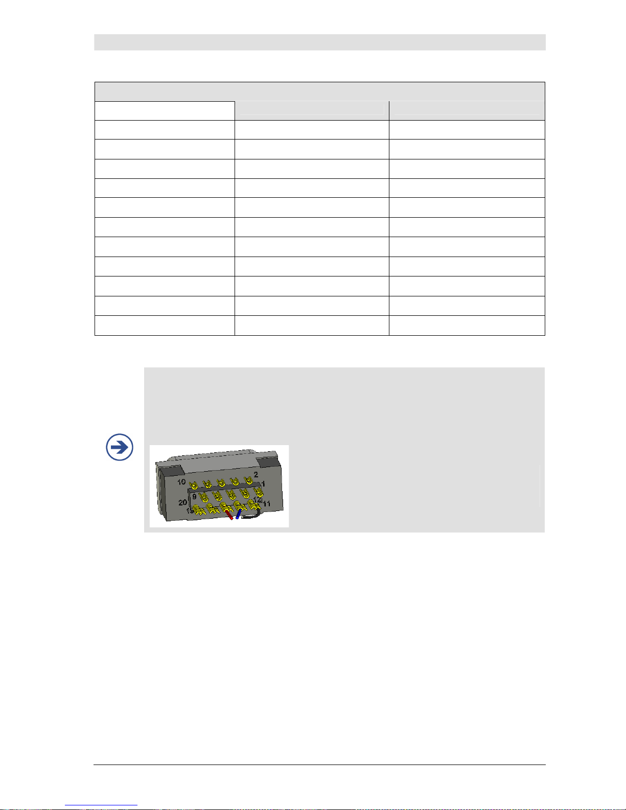
Appendix C
CNAP™ Monitor 500 Page 15-5 Version 3.5.1, PN: 21-FHZU-10002
AUX (analog output port)
Channel 1 Channel 2
Voltage range +-12 V +-12 V
Reference
0 / 5 V (0 / 500 mmHg)
-5 / +5 V (0 / 500 mmHg)
Sensitivity 100 mmHg/V 50 mmHg/V
Sampling frequency 100 Hz 100 Hz
Output Offset
+/- 50 mV
+/- 50 mV
Output Accuracy
5%
5%
Output Internal Resistor
100 Ohm
100 Ohm
Output Current
max. 2 mA
max. 2 mA
Resolution Impedance
12bit 12bit
Isolation (1sec)
4 KVDC min. 4 KVDC min.
Isolation (>1sec)
1.5 KVDC min. 1.5 KVDC min.
NOTE:
• When configuring the interface cable for the AUX analog out connector, insert a 10-
100nF ceramic capacitor between ground and signal pin to reduce noise.
PIN configuration:
• ground (schwarz): Pin 11
• channel 1 (rot): Pin 16
• channel 2 (blau): Pin 14
Page 97
Appendix C
CNAP™ Monitor 500 Page 15-6 Version 3.5.1, PN: 21-FHZU-10002
15.3 Electromagnetic compatibility
Medical electric devices have to comply with special safety regulations regarding EMC (electromagnetic
compatibility). Please keep in mind the respective precautions in this operator's manual before installing and operating the CNAP™ Monitor 500.
Also, pay attention to the fact that portable and mobile HF-communication devices (e.g. mobile
phones) may interfere with medical electric devices.
The CNAP™ Monitor 500 must not be placed immediately beside or stockpiled with other devices. If
there is no other way but to operate the CNAP™ Monitor 500 immediately beside or stockpiled with
other devices, the CNAP™ Monitor 500 must be closely observed to ensure its normal operability within this arrangement of devices.
Only original CNSystems Medizintechnik AG accessories and power cords are to be used with this device! Authorized accessories and replacement parts are listed in "Appendix B – Accessories" in this
operator's manual. Using third party manufacturer accessories may result in increased electromagnetic emission or in decreased functional immunity of the CNAP™ Monitor 500.
As electric and magnetic fields may interfere with the functional reliability of the device, avoid using
the CNAP™ Monitor 500 close to devices emitting powerful electromagnetic fields, e.g. x-ray equipment, diathermy applications or magnetic resonance tomographs.
Guidelines and manufacturer's declaration – electromagnetic emissions
The CNAP™ Monitor 500 is intended for use in an electromagnetic environment as specified below. The customer or operator of the CNAP™ Monitor 500 is to ensure it is used in such an environment.
Emission test Compliance Electromagnetic environment -
guidelines
RF emissions
CISPR 11
Group 1
The CNAP™ Monitor 500 uses RF energy only for its internal function.
Therefore, its RF emissions are very
low and are not likely to cause any
interference in nearby electronic
equipment.
RF emissions
CISPR 11
Class B
Harmonic emissions
IEC 61000-3-2
NA
Voltage fluctuations/ flicker emissions
IEC 61000-3-3
NA
The CNAP™ Monitor 500 is suitable for
use in all establishments, including
domestic establishments and those
directly connected to the public low
voltage power supply network that
supplies buildings used for domestic
purposes.
Table 201 from EN 60601-1-2:2003
Page 98

Appendix C
CNAP™ Monitor 500 Page 15-7 Version 3.5.1, PN: 21-FHZU-10002
Guidelines and manufacturer's declaration – electromagnetic immunity
The CNAP™ Monitor 500 is intended for use in an electromagnetic environment as specified below. The customer or operator of the CNAP™ Monitor 500 is to ensure that it is used in such an environment.
Immunity test IEC 60601 test level Level of compli-
ance
Electromagnetic environ-
ment - guidelines
Electrostatic
discharge (ESD)
IEC 61000-4-2
± 6 kV contact
± 8 kV air
± 6 kV contact
± 8 kV air
Floors should be wooden,
concrete or ceramic tile. If
floors are covered with synthetic material, relative humidity should be at least
30%.
Electrical fast transient
/ burst
IEC 61000-4-4-
± 2 kV for power
supply lines
± 1 kV
for
input/output lines
± 2 kV
for power
supply lines
Mains power supply quality
should be that of a typical
commercial or hospital environment.
Surge
IEC 61000-4-5
± 1 kV
differential mode
± 2 kV
common mode
± 1 kV
differential mode
± 2 kV
common mode
Mains power supply quality should be that of a
typical commercial or hospital environment.
Voltage dips, short
interruptions and volt-
age variations on power
supply input lines
IEC 61000-4-11
< 5% UT
(> 95% dip in UT)
for 0.5 cycle
40% UT
(60% dip in UT
for 5 cycles
70% UT
(30% dip in UT)
for 25 cycles
< 5% UT
(> 95% dip in UT)
for 5 sec
< 5% UT
(> 95% dip in UT)
for 0.5 cycle
40% UT
(60% dip in UT)
for 5 cycles
70% UT
(30% dip in UT)
for 25 cycles
< 5% UT
(> 95% dip in UT)
for 5 sec
Mains power quality
should be that of a typical
commercial or hospital
environment. If the operator of the CNAP™ Monitor
500 requires continued
operation during power
mains interruptions, it is
recommended that the
CNAP™ Monitor 500 be
powered from an uninterruptible power supply or a
battery.
Power frequency (50
Hz/60 Hz)
magnetic field
IEC 61000-4-8
3 A/m
3 A/m
Power frequency magnetic
fields should be at levels
characteristic of a typical
location in a typical commercial or hospital environment.
Note: UT is the a.c. mains voltage prior to application of the test level.
Table 202 from EN 60601-1-2:2003
Page 99
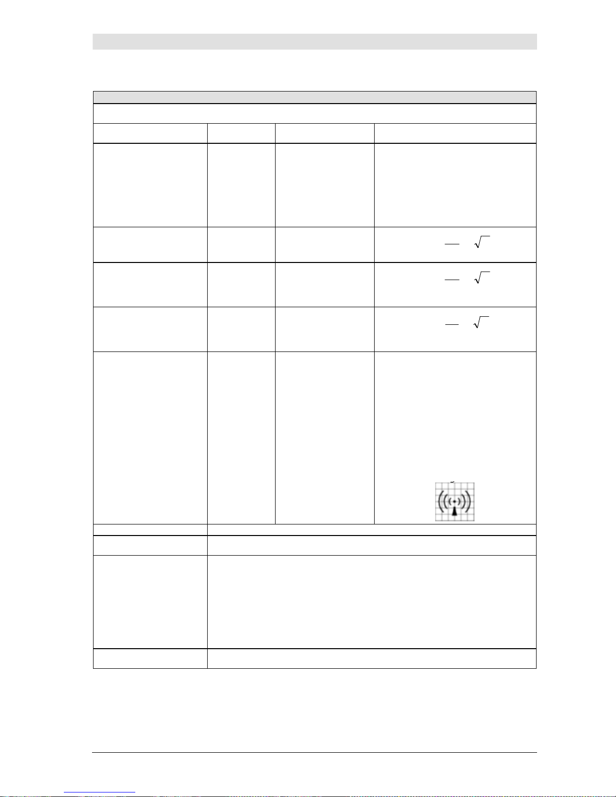
Appendix C
CNAP™ Monitor 500 Page 15-8 Version 3.5.1, PN: 21-FHZU-10002
Guidelines and manufacturer's declaration – electromagnetic immunity
The CNAP™ Monitor 500 is intended for use in an electromagnetic environment as specified below. The cus-
tomer or operator of the CNAP™ Monitor 500 is to ensure that it is used in such an environment.
Immunity test IEC 60601
test level
Compliance level Electromagnetic environment -
guidelines
Portable and mobile RF communication equipment should be used no
closer to any part of the CNAP™ Monitor 500, including cables, than the
recommended separation distance
calculated from the equation applicable to the frequency of the transmitter.
Recommended separation distance:
Conducted RF
IEC 61000-4-
3 V
rms
150 kHz to
80 MHz
3 1V in V
P
V
d ∗
=
1
5,3
Radiated RF
IEC 61000-4-3
3 V/m
80 MHz to
2.5 GHz
3
1
E
in V/m
P
E
d
∗
=
1
5,3
for 80 MHz to 800 MHz
P
E
d
∗
=
1
7
for 800 MHz to 2.5 GHz
Where P is the maximum output power rating of the transmitter in watts
(W) according to the transmitter
manufacturer and d is the recommended separation distance in meters
(m).
Field strengths from fixed RF transmitters, as determined by an electromagnetic site survey, should be less
than the compliance level in each
frequency range b.
Interference may occur in the vicinity
of equipment marked with the following symbol:
Note 1 At 80 MHz and 800 MHz, the higher frequency range applies.
Note 2
These guidelines may not apply in all situations. Electromagnetic propagation
is affected by absorption and reflection from structures, objects and people.
a Field strengths from fixed transmitters, such as base stations for radio (cellu-
lar/cordless) telephones and land mobile radios, amateur radio, AM and FM
radio broadcast and TV broadcast cannot be predicted theoretically with accuracy. To assess the electromagnetic environment due to fixed RF transmitters,
an electromagnetic site survey should be considered. If the measured field
strength in the location in which the CNAP™ Monitor 500 is used exceeds the
applicable RF compliance level above, the CNAP™ Monitor 500 should be observed to verify normal operation. If abnormal performance is observed, additional measures may be necessary, such as reorienting or relocating the
CNAP™ Monitor 500.
b Above the frequency range 150 kHz to 80 MHz, field strengths should be less
than 1 V/m.
Table 204 from EN 60601-1-2:2003
Page 100
Appendix C
CNAP™ Monitor 500 Page 15-9 Version 3.5.1, PN: 21-FHZU-10002
Recommended separation distance between portable and mobile RF-communication devices and
the CNAP™ Monitor 500
The CNAP™ Monitor 500 is intended for use in an electromagnetic environment with controlled RF disturbances.
The customer or operator of the CNAP™ Monitor 500 can avoid electromagnetic disturbances by complying with
the minimum distance between portable or mobile RF-communication equipment (transmitter) and CNAP™
Monitor 500, depending on the power output of the communication equipment as specified below.
Rated power output of
the transmitter W
Separation distance depending on the transmitting frequency m
150 kHz to 80 MHz
P
V
d
∗
=
1
5,3
80 MHz to 800 MHz
P
E
d
∗
=
1
5,3
800 MHz to 2.5
GHz
P
E
d
∗
=
1
7
0.01
0.12 0.12 0.23
0.1
0.37 0.37 0.74
1
1.17 1.17 2.33
10
3.69 3.69 7.38
100
11.67 11.67 23.33
For transmitters whose maximum rated power output values are not listed in the above list, the minimum distance can be calculated depending on the transmitting frequency and rated power output by means of the respective formula, whereas the maximum rated power output is P in watts (W) according to the specification of
the manufacturer.
Note 1
At 80 MHz and 800 MHz, the higher frequency range applies.
Note 2
These guidelines may not apply in all situations. Electromagnetic propagation
is affected by absorption and reflection from structures, objects and people.
Table 206 from EN 60601-1-2:2003
15.4 Maintenance schedule
Maintenance for the CNAP™ Monitor 500 is defined as follows:
• Safety inspection: 12 months interval
• Manintenance: 24 months interval
15.4.1 Safety inspection
The safety inspection includes the following activities:
• Visual inspection of the device
o damages,
o hygienic condition and
o safety relevant labeling (labels, signs)
• Functional technical inspection and check
• Overall assessment
• Safety test including leakage current measurement acc. EN 60601-1
• Calibration of NBP module
• Documentation including: safety protocol, inspection sticker, shipping documents
 Loading...