

CNPV CNPV-PS-M-S0010-IEC Installation Instruction
IEC INSTALLATION INSTRUCTION AND
MAINTENANCE MANUAL
FOR CRYSTALLINE SOLAR PV MODULE
TECHNICAL SPECIFICATION
TITLE:
IEC INSTALLATION INSTRUCTION
MANUAL FOR THE CRYSTALLINE
SOLAR PHOTOVOLTAIC MODULE
AUTHOR(S):
Bypina Veerraju Chaudary, Yang Xiaowu
SPEC. NO.: CNPV-PS-M-S0010-IEC
REVISION: J
EFFECTIVE DATE: July 2012
Page 1 of 15
1. INTRODUCTION
This installation instruction manual provides information about CNPV Crystalline Solar Photovoltaic Modules.
CNPV Dongying Solar Power Company Limited has a history of successful innovation within the Solar Industry.
The company was founded in 2006 and has made significant investments in research and development, creating over
10 patents during the company’ history.
The company has several fully integrated product lines including ingots, casting, wafers, Cells and Modules of Mono
and Poly crystalline, and those products are also exported to overseas markets. With an experienced international
management team and a strong reputation for innovation, CNPV is one of the leaders in China’s Solar Energy Sector
and provides the highest quality SPV Modules in a range of sizes designed to meet the requirements of the most
demanding energy and power users worldwide.
2. POWER MODULE
CNPV Solar Photovoltaic Modules consist of a series of electrically interconnected crystallin e silicon solar cells,
which are permanently encapsulated between a low iron toughened glass superstrate and substrate. The entire
laminate is secured within an anodized aluminum frame for structural strength; ease of installation and to protect the
cells from the most severe environmental conditions.
3. APPLICATIONS
CNPV SPV Modules are a highly reliable, virtually maintenance-free direct current (DC) power source, designed to
operate most efficiently in sunlight. CNPV series Modules are ideal to power remote homes, recreational vehicles,
water pumps, telecommunication systems and many other applications either with or without the use of storage
batteries.
4. PERMIT
Before installing your system, contact local authorities to determine the necessary permit, installation and inspection
requirements.
5. CLIMATE CONDITION
Install the CNPV Solar Photovoltaic Crystalline series Modules in the following conditions:
Ambient temperature: -20°C to +40°C.
Operating temperature: -40°C to +85°C.
Storage temperature: -40°C to +40°C,
Humidity: below 85RH%
Wind pressure: below 50.12lb / ft
Snow Load Pressure: below 112.76lb / ft
Corrosion resistance: Except for heavy corrosive salt area and sulfurous area.
2
(2400Pa).
2
(5400Pa).
Shengli Industry Park, Dongying City, Shandong Province 257000, PRC
http//www.cnpv-power.com E-mail: marketing@cnpv-power.com Tel: +86-546-7795555, Fax: +86-546-7795777
CNPV Dongying Solar Power Company Limited,
TECHNICAL SPECIFICATION
TITLE:
IEC INSTALLATION INSTRUCTION
MANUAL FOR THE CRYSTALLINE
SOLAR PHOTOVOLTAIC MODULE
AUTHOR(S):
Bypina Veerraju Chaudary, Yang Xiaowu
SPEC. NO.: CNPV-PS-M-S0010-IEC
REVISION: J
EFFECTIVE DATE: July 2012
Page 2 of 15
6. SITE SELECTION
In most applications, CNPV SPV Modules should be installed in a location where they will receive maximum
sunlight throughout the year. In the Northern Hemisphere, the Module should typically face south, and in the
Southern Hemisphere, the Modules should typically face north. Modules facing 30 degrees away from true South (or
North) will lose approximately 10 to 15 per cent of their power output. If the Module faces 60 degrees away from
true South (or North), the power loss will be 20 to 30 per cent.
When choosing a site, avoid trees, buildings or obstruct ions, which could cast shadows on the solar photovoltaic
Modules especially during the winter months when the arc of the sun is lowest over the horizon. Shading causes loss
of output, even though the factory fitted bypass diodes of the SPV Module will minimize any such loss.
Do not install the SPV Module near naked flame or flammable materials.
Do not install the SPV Module in a location where it would b e immersed in water or continually exposed to water
from a sprinkler or fountain etc.
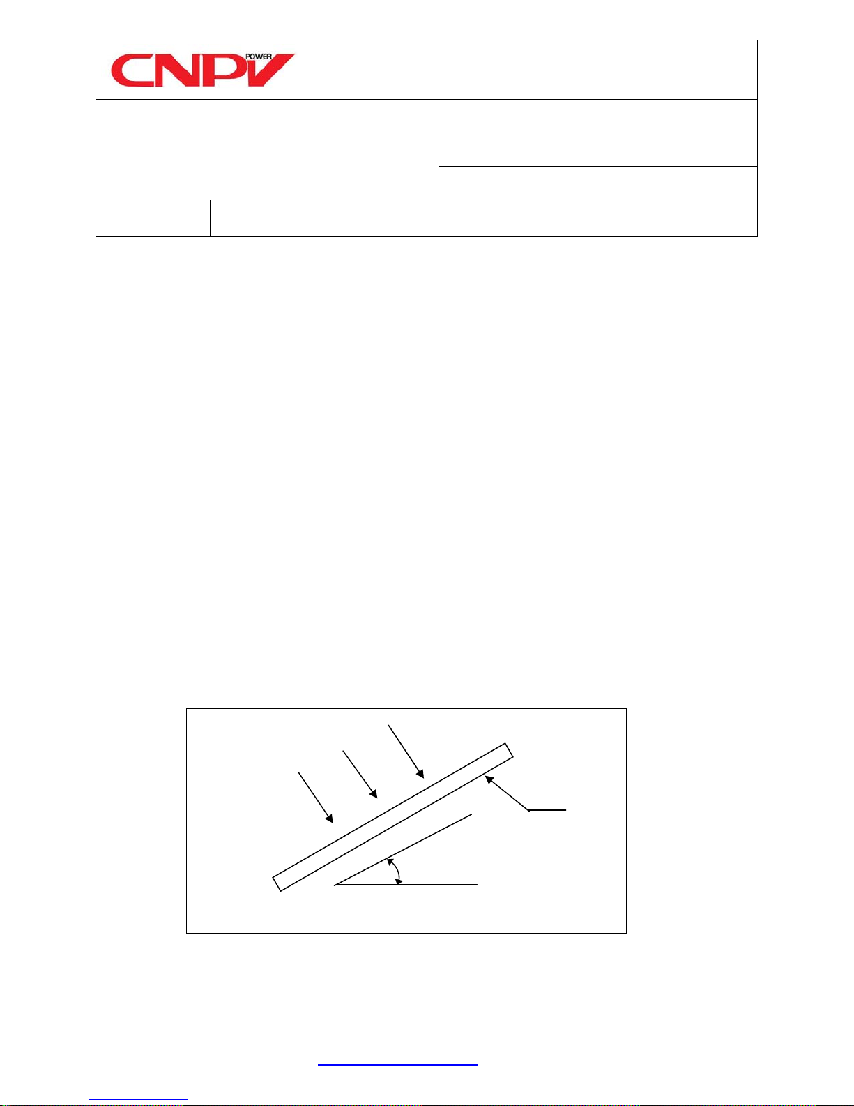
7. MODULE TILT ANGLE
CNPV SPV Modules connected in series should be installed at same orientation and angle. Different orientation or
angle may cause loss of output power due to difference of amount of sunlight exposed to the Module.
CNPV SPV Modules produce the most power when they are pointed directly at the sun. For installations where the
SPV Modules are attached to a permanent structure, the SPV Modules should be tilted for optimum winter
performance. As a rule, if the system power production is adequate in winter, it will be satisfactory during the rest of
the year. The Module tilt angle is measured between the solar Modules and the ground (Figure 1). Optimal tilting o f
SPV Module is almost the same as the latitude of installation location.
SUNLIGHT
MODULE
TILT ANGLE
HORIZONTAL
Figure 1 SPV Module Tilt Angle
Shengli Industry Park, Dongying City, Shandong Province 257000, PRC
http//www.cnpv-power.com E-mail: marketing@cnpv-power.com Tel: +86-546-7795555, Fax: +86-546-7795777
CNPV Dongying Solar Power Company Limited,
TECHNICAL SPECIFICATION
TITLE:
IEC INSTALLATION INSTRUCTION
SPEC. NO.: CNPV-PS-M-S0010-IEC
MANUAL FOR THE CRYSTALLINE
SOLAR PHOTOVOLTAIC MODULE
REVISION: J
EFFECTIVE DATE: July 2012
AUTHOR(S):
Bypina Veerraju Chaudary, Yang Xiaowu
Page 3 of 15
8. MOUNTING AND NOTES
Systems should be installed by qualified personnel only. It involves electricity, and can be dangerous if the personnel
are not familiar with the appropriate safety procedures.
The Module frame is made of anodized aluminum, and therefore corrosion can occur if the Module is subject to a
salt water environment with contact to a rack of another type of metal (Electrolysis Corrosion). If required, PVC or
stainless steel washers can be placed between the SPV Module frame and support structure to prevent this type of
corrosion. Module support structures that are to be used to support SPV Modules at correct tilt angles should be wind
and snow load rated for use by the appropriate local and civil codes prior to installation.
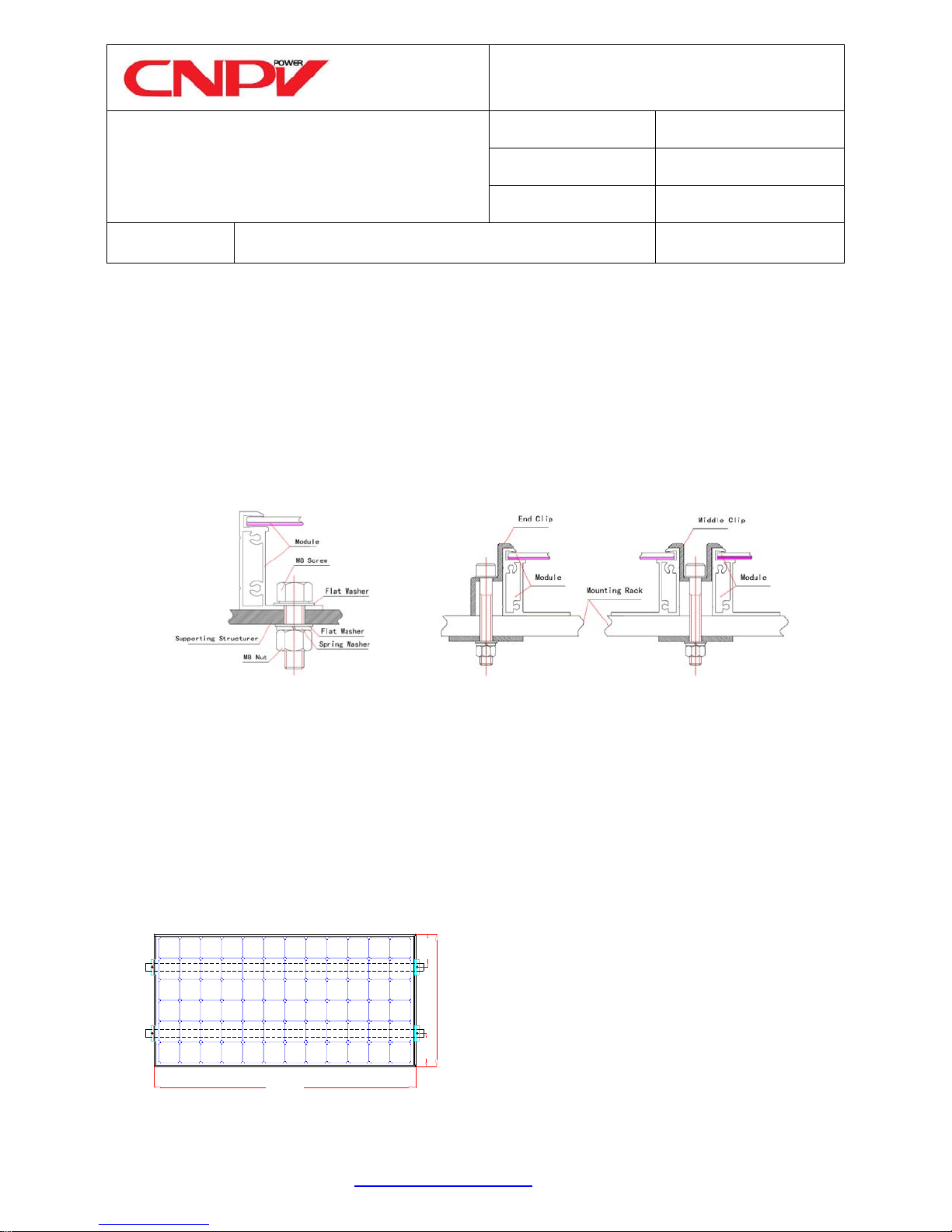
CNPV SPV Modules can be mounted as following method:
Method a: Using corrosion-proof
screws on existing Installation
Method b. Using suitable module
clamps on the module frame
Figure 2 Mounting Method a and b
a) Using corrosion-proof screws (M8) on the existing installing holes (see drawing 1, 3, 5 & 7) in the Module
frame. The frame of each Module has 4 or 8 mounting holes (12mm×9mm) used to secure the Modules to
supporting structure. The Module frame must be attached to a supporting rack using M8 stainless steel hardware
together with spring wash ers and flat washers in fo ur places symmetrical on the SPV Module. See method a of
figure 2. The applied torque is about 8 Newton-meters.
b) Using suitable Module clamps on the Module frame, see method b of figure 2. The module frame must be
attached to supporting rack using M8 stainless steel hardware together with corrosion-proof clips in four places
on the SPV module. See drawing 10, 12, 14 & 16, with clamping clip, fo r positioning of clamping clips. The
applied torque is about 8 Newton-meters. See figure 3 if clamping mounting is on short frames of the module.
1/4W1/4W
Using Short sides for module clamping. W
Width
means module width, and 1/4W means
permissible clamping range.
Figure 3. Mounting on short frames.
Length
c) Insertion System
Shengli Industry Park, Dongying City, Shandong Province 257000, PRC
http//www.cnpv-power.com E-mail: marketing@cnpv-power.com Tel: +86-546-7795555, Fax: +86-546-7795777
CNPV Dongying Solar Power Company Limited,
TECHNICAL SPECIFICATION
TITLE:
IEC INSTALLATION INSTRUCTION
MANUAL FOR THE CRYSTALLINE
SOLAR PHOTOVOLTAIC MODULE
AUTHOR(S):
Bypina Veerraju Chaudary, Yang Xiaowu
SPEC. NO.: CNPV-PS-M-S0010-IEC
REVISION: J
EFFECTIVE DATE: July 2012
Page 4 of 15
NOTES:
(1) The Module clamps must not come into contact with the front glass and must not deform the frame. Avoid
shadowing effects from the Module clamps and the insertion systems. It is not permitted to modify the Module frame
under any circumstances. Recommended distance between 2 Solar Modules is 5mm considering linear thermal
expansion of the Module frames.
(2) Clearance between the Module frame and mounting surface may be required to prevent the junction box from
touching the surface, and to circulate cooling air around the back of the Module.
(3) The Modules are not designed for integral mounting as part of a roof or wall. The mounting design may have an
impact on the fire resistance. If the Modules are to be installed on the roof or wall of a building, the fire resistance of
roof covering or wall should be rated for the application. Here the standoff method or the rack method is
recommended. The Modules are supported parallel to surface of the building wall or roof. Clearance between the
Module frames and surface of the wall or roof is required to prevent wiring damage and to allow air to circulate
behind the Module. The recommended stand-off height is 115mm. Any slope less than 5in/ft (127mm/305mm)
required to maintain a fire class rating. Do not mount SPV Module in such way that the drain holes of SPV Module
are intended to block up.
(4) Do not step on the Module, although SPV Modules are quite rugged , the glass can be broken (and the Module
will no longer work properly) if it is dropped or hit by tools or other objects.
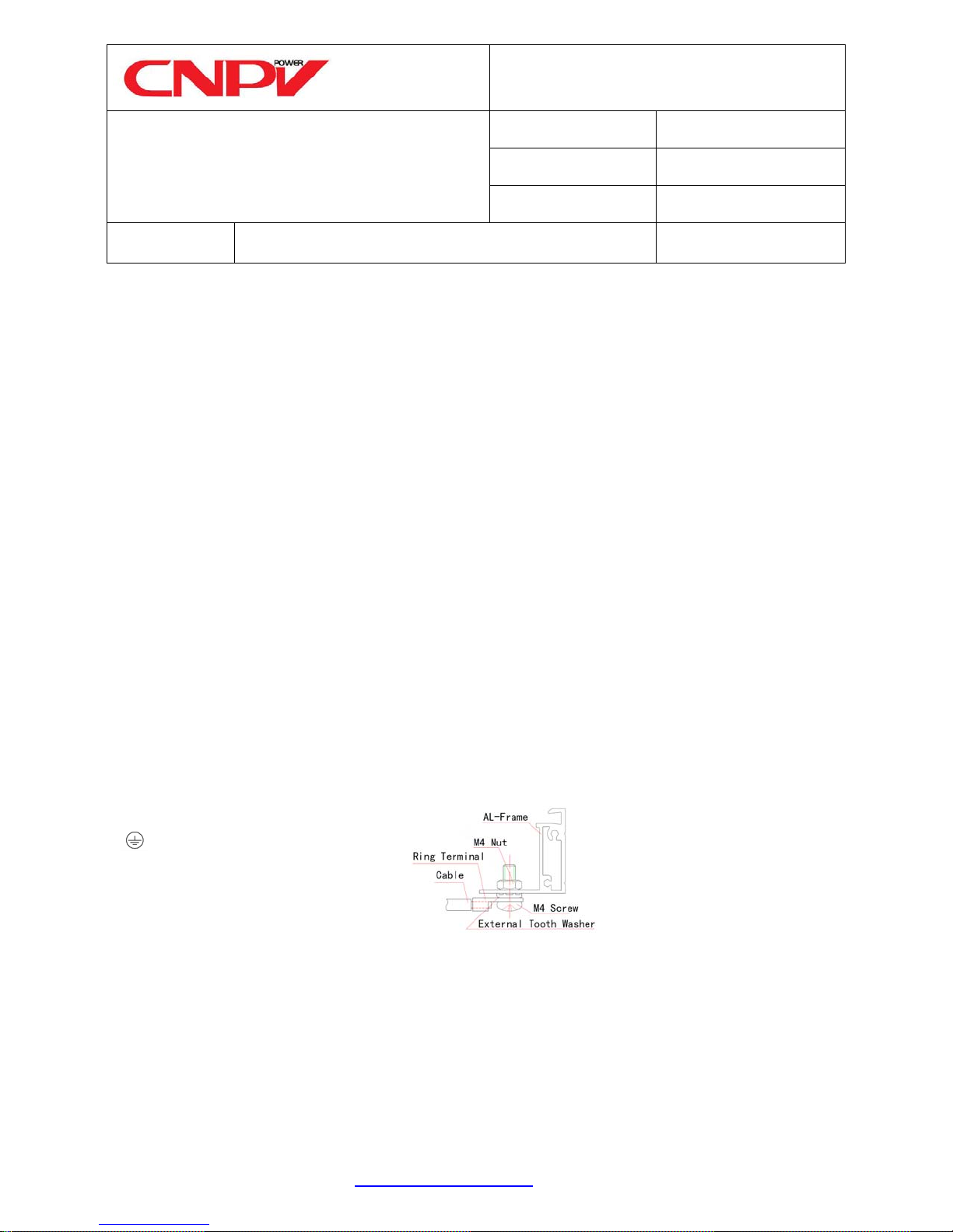
9. GROUNDING
All Module frames and mounting racks must be properly grounded in accordance with the local regulations. Proper
grounding is achieved by connecting the Module frame(s) and structural members contiguously one to another using
a suitable grounding conductor. The grounding con ductor or strap may be copper, copper alloy, or other material
acceptable for use as an electrical conductor per local regulations. The grounding conductor must then make a
connection to earth using a suitable earth ground electrode.
Attach a separate conductor to one of the
4mm diameter grounding holes marked
'
' on the Module frame with a screw
and nut that incorporates an external tooth
washer. This is to ensure positive electrical
contact with the frame.
The rack must also be grounded unless they are mechanically connected by nuts and bolts to the grounded SPV
Modules. The array frame shall be grounded in accordance with local regulations.
Figure 4 Schematic drawing
for SPV Module grounding
Shengli Industry Park, Dongying City, Shandong Province 257000, PRC
http//www.cnpv-power.com E-mail: marketing@cnpv-power.com Tel: +86-546-7795555, Fax: +86-546-7795777
CNPV Dongying Solar Power Company Limited,
 Loading...