

Page 1
Status: 29.11.2017
Operating Ins tructions
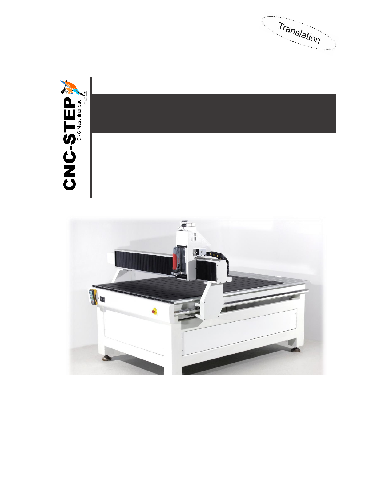
T-Rex-Series
T-Rex 0609 ▪ T-Rex 0712 ▪ T-Rex 1215 ▪ T-Rex 1224
https://www.cnc-step.de/en
Page 2
Operating Instructions
T-Rex-Series
CNC-STEP e.K. ▪ Siemensstrasse 13-15 ▪ 47608 Geldern ▪ Germany
Page 2
Support: +49 (0)2831/91021-50
31.03.2014
T-Rex-Series
Short description
The machine includes the complete mechanics for three-dimensional movement. The linear
carriage-movement takes place via threaded spindles, powered by step motors. Two drives are used
on the x-axis. The activation of the step motors, in order to operate every single axis, is done by
using further interfaces. This operating description will show you how to install, operate and service
a CNC- portal system.
Page 3

Operating Instructions
T-Rex-Series
CNC-STEP e.K. ▪ Siemensstrasse 13-15 ▪ 47608 Geldern ▪ Germany
Page 3
Support: +49 (0)2831/91021-50
31.03.2014
Contents
1 GENERAL ..................................................................................................................... 7
1.1 Symbol description ................................................................................................................... 7
1.2 Limitation of Liability .............................................................................................................. 8
1.3 Copyright .................................................................................................................................. 8
2 SAFETY ........................................................................................................................ 9
2.1 Intended use .............................................................................................................................. 9
2.2 Fundamental dangers ............................................................................................................ 10
2.2.1 Hazards from electrical power ........................................................................................... 10
2.2.2 Dangers by mechanics ....................................................................................................... 11
2.2.3 Dangers by high or very low temperatures ........................................................................ 13
2.2.4 Risk of fire ......................................................................................................................... 13
2.2.5 Radiation hazards .............................................................................................................. 14
2.2.6 Hazards of chemicals ......................................................................................................... 14
2.2.7 General work-related dangers ............................................................................................ 15
2.3 Responsibility of the operator ............................................................................................... 16
2.4 Staff requirements .................................................................................................................. 17
2.4.1 Qualification ...................................................................................................................... 17
2.4.2 Instruction .......................................................................................................................... 18
2.5 Personal protective equipment .............................................................................................. 18
2.6 Safety installations .................................................................................................................. 19
2.6.1 Description of the installed safety installations ................................................................. 20
2.6.2 Safety installations, which have to be updated by the owning operator ............................ 21
2.7 Behaviour in case of fire or accidents ................................................................................... 21
2.8 Environmental protection...................................................................................................... 22
2.9 Signage ..................................................................................................................................... 22
2.9.1 Mandatory signs ................................................................................................................ 23
2.9.2 Prohibition signs ................................................................................................................ 23
2.9.3 Warnings ............................................................................................................................ 24
2.9.4 Fire protection signs .......................................................................................................... 25
2.9.5 Exit signs ........................................................................................................................... 26
3 TECHNICAL SPECIFICATIONS ................................................................................ 27
3.1 General information ............................................................................................................... 27
Page 4

Operating Instructions
T-Rex-Series
CNC-STEP e.K. ▪ Siemensstrasse 13-15 ▪ 47608 Geldern ▪ Germany
Page 4
Support: +49 (0)2831/91021-50
31.03.2014
3.2 Power values ........................................................................................................................... 29
3.3 Operating conditions .............................................................................................................. 29
3.4 Working materials .................................................................................................................. 29
3.5 Emissions ................................................................................................................................. 30
3.6 Type plate ................................................................................................................................ 30
4 STRUCTURE AND FUNCTIONS ................................................................................ 31
4.1 Overview ................................................................................................................................. 31
4.2 Short description for the area of application ....................................................................... 32
4.3 Module description ................................................................................................................. 33
4.3.1 Z-axis with carriage ........................................................................................................... 33
4.3.2 Y-axis with carriage ........................................................................................................... 34
4.3.3 X-axis with carriage ........................................................................................................... 35
4.3.4 Tool holder ........................................................................................................................ 36
4.4 Operating elements ................................................................................................................ 36
4.5 Connections ............................................................................................................................. 37
4.5.1 Control signals(ST)............................................................................................................ 37
4.5.2 rotation axis / tangential knife (C) ..................................................................................... 38
4.5.3 Motor connection (X, Y, Z) ............................................................................................... 38
4.5.4 HF-spindle connection ....................................................................................................... 39
4.6 Work and danger areas ......................................................................................................... 39
4.6.1 Working area ..................................................................................................................... 39
4.6.2 Danger zone ....................................................................................................................... 39
5 TRANSPORT, PACKAGING AND STORAGE ........................................................... 40
5.1 Safety instructions for transport ........................................................................................... 40
5.2 Transport inspections ............................................................................................................ 41
5.3 Packaging ................................................................................................................................ 41
5.4 Symbols on packaging ............................................................................................................ 42
5.5 Transport ................................................................................................................................ 43
5.6 Storage ..................................................................................................................................... 44
6 INSTALLATION AND COMMISSIONING ................................................................. 45
6.1 Safety instructions for the installation and commissioning ................................................ 45
6.2 Preparations ............................................................................................................................ 46
6.2.1 Install machine ................................................................................................................... 46
Page 5

Operating Instructions
T-Rex-Series
CNC-STEP e.K. ▪ Siemensstrasse 13-15 ▪ 47608 Geldern ▪ Germany
Page 5
Support: +49 (0)2831/91021-50
31.03.2014
6.3 Installation .............................................................................................................................. 47
6.3.1 Connecting the computer ................................................................................................... 47
6.3.2 Connecting the stepper motor and control cable ............................................................... 48
6.3.3 Installing Accessories ........................................................................................................ 49
6.4 Initial start-up ......................................................................................................................... 50
7 OPERATION ............................................................................................................... 51
7.1 Safety guidelines for operation .............................................................................................. 51
7.2 Operations before usage ........................................................................................................ 51
7.3 Switching on ............................................................................................................................ 52
7.4 Activities during operation .................................................................................................... 53
7.4.1 Operating machine ............................................................................................................. 53
7.4.2 Change tool ........................................................................................................................ 56
7.5 Switching off ........................................................................................................................... 56
7.6 Activities after use .................................................................................................................. 57
7.7 Emergency Shutdown ............................................................................................................ 57
8 MAINTENANCE ......................................................................................................... 58
8.1 Safety Instructions for maintenance ..................................................................................... 58
8.2 Spare parts .............................................................................................................................. 59
8.3 Maintenance Schedule ........................................................................................................... 60
8.4 Maintenance ............................................................................................................................ 61
8.4.1 Cleaning of the machine .................................................................................................... 61
8.4.2 Lubricate machine ............................................................................................................. 62
8.5 Measures after maintenance ................................................................................................. 65
9 FAILURES .................................................................................................................. 66
9.1 Cautions for Troubleshooting ............................................................................................... 66
9.2 Problem resolution ................................................................................................................. 68
9.3 Problem resolution ................................................................................................................. 70
9.3.1 Cancel the emergency stop ................................................................................................ 70
9.4 Commissioning after fault has been rectified ...................................................................... 70
10 DISMANTLING AND DISPOSAL ............................................................................ 71
10.1 Safety regulations for the disassembling and disposal .................................................... 71
10.2 Disassembling ...................................................................................................................... 71
Page 6

Operating Instructions
T-Rex-Series
CNC-STEP e.K. ▪ Siemensstrasse 13-15 ▪ 47608 Geldern ▪ Germany
Page 6
Support: +49 (0)2831/91021-50
31.03.2014
10.3 Disposal ................................................................................................................................ 72
11 APPENDIX ............................................................................................................... 73
11.1 Accessories ........................................................................................................................... 73
12 CUSTOMER SERVICE ............................................................................................ 74
Page 7
Operating Instructions
T-Rex-Series
CNC-STEP e.K. ▪ Siemensstrasse 13-15 ▪ 47608 Geldern ▪ Germany
Page 7
Support: +49 (0)2831/91021-50
31.03.2014
1 Genera l
This instruction provides guidelines which enable a safe and efficient handling of the machine. The
manual is an integral part of the machine and must be kept in the immediate vicinity of the machine
and accessible at any time for the personnel.
Before starting all tasks, personnel must carefully read and understand these instructions.
Adherence to all the specified safety instructions and instructions for actions in this operating
manual is a fundamental requirement for working safely.
Furthermore, the local accident prevention regulations and general safety conditions for the
application of the machine are also applicable.
Illustrations in this manual are intended to facilitate basic understanding, and may differ from the
actual design.
Further guidelines regarding built-in components are found in the appendix of this description.
1.1 Symbol description
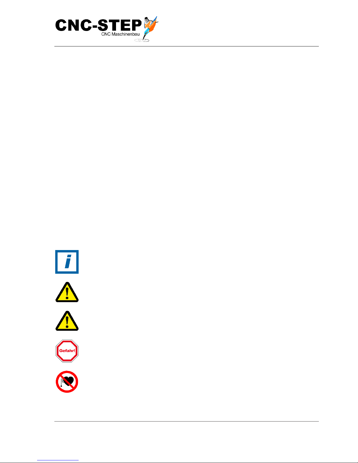
Safety instructions are designated by symbols. In addition, there is always a signal word
heading the information indicating the severity of the danger or hazard that may be
encountered.
HINT:
Indicates a potentially hazardous situation which, if not avoided, could result in
property damage or environmental contamination.
WARNING:
This signal word and symbol indicates a risk which can lead to severe injury or even
death, if not avoided.
ATTENTION:
This signal word and symbol indicates a risk which can lead to small injuries, if not
avoided.
Danger:
This signal word and symbol indicates a risk which can lead to severe injury or even
death, if not avoided.
Prohibition for people with pacemakers
This sign stands for activities involving risks for people with pacemakers. These areas
are prohibited for people with pacemakers!!
Page 8
Operating Instructions
T-Rex-Series
CNC-STEP e.K. ▪ Siemensstrasse 13-15 ▪ 47608 Geldern ▪ Germany
Page 8
Support: +49 (0)2831/91021-50
31.03.2014
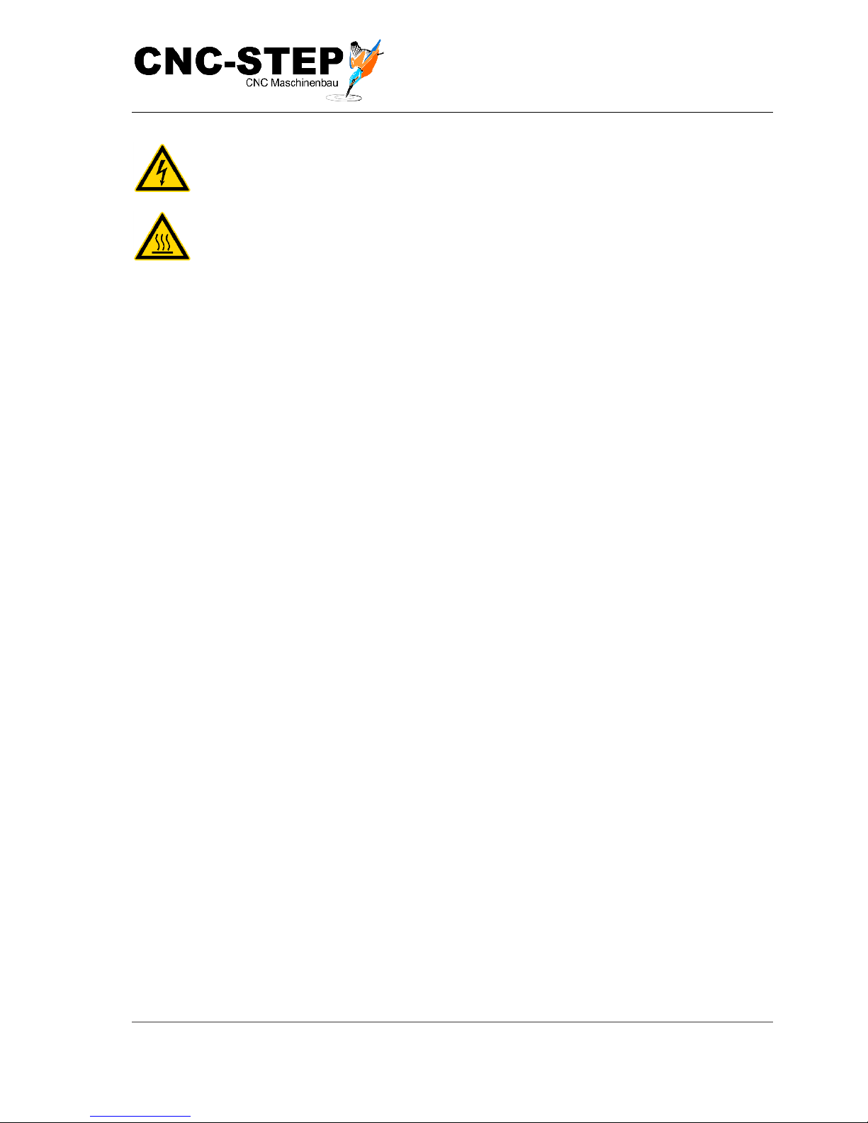
Warning of hazardous electrical voltage
This sign stands for activities on all components carrying live voltage.
Danger due to hot surface
This sign stands for activities involving contact with hot objects.
1.2 Limitation of Liability
All data and notes in these instructions were prepared with consideration to the statutory standards
and regulations, the present state of technology, as well as our many years of knowledge and
experience.
Under the following circumstances the manufacturer will not assume any liability:
• Non-compliance with these instructions
• Used other than for the intended purpose
• Unauthorized or unapproved personnel
• Unauthorised rebuilds or modifications
• Unauthorized technical changes
• The use of unauthorized replacement parts or non-original accessories
The actual scope of delivery can, by special designs, deviate from the explanations and
presentations given here, because of the utilization of additional order options, or because of the
most recent technical changes.
The responsibilities agreed in the delivery contract, the General Terms and Conditions as well as the
delivery conditions of the manufacturer and the statutory regulations valued at the time of
conclusion of the contract are effective.
1.3 Copyright
The contents of this instruction are copyrighted. It is to be used for the purpose of operating the
machine, only. Any other use without a written permission is forbidden.
Page 9
Operating Instructions
T-Rex-Series
CNC-STEP e.K. ▪ Siemensstrasse 13-15 ▪ 47608 Geldern ▪ Germany
Page 9
Support: +49 (0)2831/91021-50
31.03.2014
2 Safet y
This section gives an overview of all important safety aspects for optimum protection of the
personnel, as well as for the safe and fault-free operation. Other task-based guide-lines are included
in the sections regarding the individual phases of life.
2.1 Intended use
The CNC-Portal system is exclusively used for holding provided tools that serve to process various
materials and surfaces.
The machine is meant to be built into a complete system and does not have its own control unit.
Intended use also includes compliance with instructions specified by the manufacturer concerning
operation, servicing and maintenance.
Every application in excess of the intended use and/or other use, can lead to hazardous situations
and is considered misuse.
WARNING:
Danger due to misuse!
Improper use of the CNC-portal machine can cause dangerous situations.
• Operation outside the values specified in the section „Technical data“.
• Bypassing the safety devices.
• Remodelling, refitting or changing of the device or parts of it, with the
intention to alter functionality or usability.
• If machining process involves flammable cooling lubricants.
• Processing light alloys such as aluminium, magnesium and titanium alloys
without extraction attachments and corresponding safety measures.
• Operating the machine, although it is not in perfect condition from a technical
point of view.
• Operating the machine in potentially explosive environment.
The manufacturer shall not be held liable for any and all damage due to misuse of this
equipment.
Page 10
Operating Instructions
T-Rex-Series
CNC-STEP e.K. ▪ Siemensstrasse 13-15 ▪ 47608 Geldern ▪ Germany
Page 10
Support: +49 (0)2831/91021-50
31.03.2014
2.2 Fundamental dangers
In following section, all residual risks are named that can still result from the machine, even when
the appliance is used as intended.
In order to minimize personal injuries and property damage and avoid dangerous situations, all here
mentioned safety-guidelines and those mentioned in further sections must be followed.
2.2.1 Ha za rd s fr o m e l e c t r i c a l po wer
Electric current
DANGER:
Life Hazard through electrical shock!!
Touching conductive parts causes a direct danger to due to electrical shock.
Damage to the insulation or individual components can mean danger to life.
• Any work required at the electrical system may only be carried out by a
qualified electrician in compliance with electro-technical regulations.
• In case of damage to the insulation, switch off the power supply
immediately and have repairs carried out.
• Before starting to work on active parts of electrical systems and equipment,
establish a voltage-free state throughout the duration of the work, this must
take place according to the 5 following safety regulations:
➢ Activation.
➢ Secure it from being switched on again.
➢ Determine voltage free status.
➢ Earth and short circuit.
➢ Provide protection by covers or barriers for any neighbouring live parts.
• Never attempt to bypass or de-activate fuses or cut-outs. When replacing fuses
or circuit breakers make sure to adhere to the correct ampere rating. Keep
moisture away from live parts.
Page 11
Operating Instructions
T-Rex-Series
CNC-STEP e.K. ▪ Siemensstrasse 13-15 ▪ 47608 Geldern ▪ Germany
Page 11
Support: +49 (0)2831/91021-50
31.03.2014
Stored charge
Danger:
Risk of death due to stored voltage!
Electronic charges could be stored in electric components that still exist after
switching off and disconnecting from power-supply. Contact with these components
can lead to severe injury or even death.
• Before starting work disconnect mentioned components from power-supply.
Wait 10 minutes, in order to assure that the internal capacitors discharge
completely.
2.2.2 Dange r s b y m e c h a ni c s
Rotating tools
WARNING:
Risk of injury from rotating tools!
Clamped tools such as milling spindles can lead to severe personal injury or
material damage.
• Before the start of any work, ensure that all covers and protective devices are
correctly installed and function correctly.
• Never touch moving tool during operating process!
• Before exchanging tools, always pull power plug of the milling motor or turn
off the machine and secure against restarting.
Axis motion
WARNING:
Risk of injury by axis motion!
Collision by people with components of the machine (Y-bridge, Units, turntable with
work piece, tools) can cause severe injuries.
• Body parts are kept away from moving components and axis limit switches.
• Do not reach into gaps between ball screws and adjacent components.
• Do not reach into gaps between unit and Y-bridge.
• Only work on the machine when it is idle.
• Only work with personal safety equipment.
Page 12
Operating Instructions
T-Rex-Series
CNC-STEP e.K. ▪ Siemensstrasse 13-15 ▪ 47608 Geldern ▪ Germany
Page 12
Support: +49 (0)2831/91021-50
31.03.2014
Falling materials
WARNING:
Injuries by falling materials!
During operation chips, tools (or parts of it) could be thrown out uncontrollably or
cause severe injuries to skin and eyes.
• Wear face shield or fully closed and tight-fitting goggles, protective
clothing, protective gloves and safety shoes.
• If particles enter your eyes, immediately get medical attention!
Unexpected start-up of the machine
WARNING:
Risk of injury caused by unexpected start-up of the machine
The machine and the used tools can start-up unexpectedly, change their direction or
stop. Limps can get trapped.
• It must be ensured that, no body parts get in the danger zone of the machine.
• Protect working area against unintentional access.
Tools
ATTENTION:
Risk of injuries by negligent handling of tools!
By handling tools negligent, lacerations and crushing injuries can be caused.
• Tools must be handled with care and used in accordance with the
regulations.
• Take weight into account when transporting tools.
• Wear safety shoes and protective gloves.
Sharp edges and corners
ATTENTION:
Risk of injuries by sharp edges and corners!
Sharp edges and corners can cause abrasions and cuts on your skin.
• Working near sharp edges and corners should be done with great caution.
• If in doubt wear protective gloves.
Page 13
Operating Instructions
T-Rex-Series
CNC-STEP e.K. ▪ Siemensstrasse 13-15 ▪ 47608 Geldern ▪ Germany
Page 13
Support: +49 (0)2831/91021-50
31.03.2014
2.2.3 Dange r s b y h i g h or v e r y l o w t e mp e r a tu r e s
Hot surfaces
ATTENTIONS:
Risks by hot surfaces!
Tools, work pieces and chips can heat up during operation. Skin contact with hot
surfaces causes serious burns of the skin.
• As a matter of principle, for all tasks with tools, work pieces and chips,
protective clothing and gloves must be worn.
• Before all tasks, make sure that all surfaces have cooled down to the
ambient temperature.
2.2.4 Ris k o f f i r e
Highly flammable materials
ATTENTION:
Risk of fire by highly flammable materials!
Organic dust produced by coal or wood or inorganic dust from magnesium,
aluminium, zinc or titanium can catch fire and cause severe injuries and death.
• Do not smoke within the danger zone and the immediate vicinity. Refrain
from contact with open flames or sources of ignition.
• Keep a fire extinguisher at hand in the immediate vicinity of the work area.
• Do not process light alloys such as magnesium, aluminium, zinc and
titanium without an extraction system and relevant security measures.
• Suspend any work activities in case of fire. Leave the danger zone until the
all clear signal is given
Page 14
Operating Instructions
T-Rex-Series
CNC-STEP e.K. ▪ Siemensstrasse 13-15 ▪ 47608 Geldern ▪ Germany
Page 14
Support: +49 (0)2831/91021-50
31.03.2014
2.2.5 Radia t i o n h a z ar d s
Magnetic fields
DANGER:
Danger to life by magnetic fields!
Magnetic fields of step motors can cause severe injuries or death, as well as serious
damage to materials.
• Persons with pacemakers must keep away from the machine! It can
effectively provoke a dysfunction of the pacemaker.
• Persons with metallic implants must not be allowed in the area of the
machine. Implants can heat themselves up or be drawn-in.
• Take off all metal objects (Jewellery, watches, pens etc.) before starting
maintenance operation.
• No electronica equipment is to be taken into the magnetic source area. These
could get damaged.
• No storage media, credit cards etc. are to be taken into the magnetic source
area. Containing data may be deleted.
2.2.6 Ha za rd s o f c h e m i ca l s
Cooling emulsion
WARNING:
Danger of serious damage to health by polluted cooling emulsion!
Polluted cooling emulsion can cause inflammations when coming in contact with
skin.
• Cooling emulsion must be checked at regular intervals.
• When handling with polluted cooling emulsion protective clothing and
chemical-resistant safety-gloves must be worn.
• Avoid direct skin contact. Cleanse skin, especially before breaks and when
finishing work.
• Eat and drink in relevant break room only!
Page 15
Operating Instructions
T-Rex-Series
CNC-STEP e.K. ▪ Siemensstrasse 13-15 ▪ 47608 Geldern ▪ Germany
Page 15
Support: +49 (0)2831/91021-50
31.03.2014
ATTENTION:
Health risks due to contact with cooling emulsion!
Contact with cooling emulsion may lead to health risks.
• Avoid contact with your skin.
• Remove cooling emulsion from the skin immediately.
• Do not inhale the vapours.
Oil and fat
ATTENTION:
Risk of health due contacting with oil and fat!
Contact with oil and fat may lead to health risks.
• Avoid skin contact.
• Remove oil and fat immediately from skin.
• Do not inhale vapours.
2.2.7 Gene r a l w o r k- r e l a t e d da ng e r s
Noise
ATTENTION:
Risk of injury by noise!
The noise levels occurring in the operating area may cause severe hearing damage.
• Always wear hearing protection when working.
• Only stay in the danger area when required.
Dirt and objects lying around
Attention:
Risk of tripping by dirt and objects lying around!
Soiling and objects left lying around are sources of slipping and stumbling and can
cause considerable injuries.
• Always keep the work area clean.
• Remove any objects which are no longer required from the working area,
especially those near ground.
• Designate tripping positions with yellow-black marker band.
Page 16

Operating Instructions
T-Rex-Series
CNC-STEP e.K. ▪ Siemensstrasse 13-15 ▪ 47608 Geldern ▪ Germany
Page 16
Support: +49 (0)2831/91021-50
31.03.2014
2.3 Responsibility of the operator
Operator
Operator is the person who operates the machine for commercial or economic purposes, or leaves
the use / application to a third party and bears responsibility during the operation of the product for
the protection of the user, the staff and third party.
Operator obligations
The machine is used in the commercial sector. The operator of the machine is therefore subject to
the legal obligations concerning occupational safety. Apart from the safety instructions given in this
manual, it is necessary to meet all safety, accident prevention and environmental protection
requirements applicable to the equipment's field of use and operating site.
The following principles apply in particular:
• The operating company must inform itself about the effective industrial regulations and
determine additional hazards in a risk assessment that result through the special working
conditions at the place of operating the machine. He must implement this in the form of
operating instructions for the operation of the machine.
• During the complete usage time of the machine, the owner must check whether the
operating instructions created by him correspond with the current status of the regulations
and must adapt them if necessary.
• The owner must clearly regulate and specify the responsibilities for installation, operation,
maintenance and cleaning
• The operator of the machine must ensure that all persons having access to it, have read and
understood these instructions. In addition he must at regular intervals train the employees in
how to deal with the machine and inform them about potential hazards.
• The operating company must provide the required safety equipment for the personnel and
order to wear protective equipment.
Moreover, the equipment operator is responsible for ensuring that the equipment is in proper
technical condition at all times.
Thus, following applies:
• The operating company must make sure that any and all maintenance intervals described in
this instruction are carried out.
• The owner must arrange for all safety equipment to be checked regularly for functionality
and completeness.
Page 17
Operating Instructions
T-Rex-Series
CNC-STEP e.K. ▪ Siemensstrasse 13-15 ▪ 47608 Geldern ▪ Germany
Page 17
Support: +49 (0)2831/91021-50
31.03.2014
2.4 Staff requirements
2.4.1 Qual i f i c a t i o n
The different Tasks contained in this instruction require different qualifications auf persons that are
intrusted with these tasks.
WARNING:
Risks caused by insufficient qualifications of persons!
Insufficient qualified persons cannot assess the extent to which they represent a risk
handling with the machine and therefor run the risk of injuries or death for
themselves and others.
• Work on or in the unit must be done only by duly qualified staff and in full
compliance with the appropriate instructions and pertinent regulations...
• Keep insufficiently qualified persons away from the work area.
Only persons of whom it may be expected that they perform their work reliably are permitted as
personnel. Persons whose responsiveness is affected, e.g. by drugs, alcohol or medicines are not
authorized.
In this instruction all required qualifications, for the different people, with different tasks are named
Operator
The operator was instructed by the operating company in a briefing about the tasks assigned to them
and instructed about possible hazards because of improper conduct. Tasks, die which are carried out
beyond the normal operation, only are allowed to be carried out by an operator if this is mentioned
in this instruction and the operating company has assigned the operator expressly.
Electrician
An electrician whose technical training, skills and experience together with their knowledge of
pertinent regulations and documentation means that they are capable of assessing the work to be
carried out and detect and prevent any possible dangers.
An electrician is trained especially for its working environment, and knows the relevant standards
and regulations.
Qualified personnel
Qualified personnel based on their professional training, know-how and experience as well as
knowledge of the applicable standards and regulations is able to perform assigned work activities
and to detect and to avoid possible dangers on their own.
Manufacturer
Curtain maintenance work is only allowed to be carried out by authorized and skilled personnel.
Other personnel is not authorised to carry out these tasks. In order to carry out this maintenance
work, please call our customer service!
Page 18
Operating Instructions
T-Rex-Series
CNC-STEP e.K. ▪ Siemensstrasse 13-15 ▪ 47608 Geldern ▪ Germany
Page 18
Support: +49 (0)2831/91021-50
31.03.2014
2.4.2 Ins t r u c t i o n
The owner must train staff regularly. For record-keeping purposes, a log of training conducted must
be kept with following minimum contents:
• Date of training
• Name of trained person
• Contents of training
• Name of trainer
• Signature of trained person and trainer
2.5 Personal protective equipment
Personal protective equipment prevents from impairments with respect to the safety of personnel
during work.
Personnel have to wear personal protective equipment while working on the machine, which are
mentioned in different sections of this instruction.
Description of personal protective equipment
Protective clothing
Protective clothing is close fitting, with low resistance to tearing, with narrow sleeves
and without protruding parts.
Chemical resistant safety gloves
Suitable chemical resistant safety gloves have to worn to protect your skin from
aggressive chemicals.
Hearing protection
Hearing protection prevents irreversible damage to hearing.
Industrial protection helmet
Industrial protection helmet prevents from injuries by falling or suspended objects.
Page 19
Operating Instructions
T-Rex-Series
CNC-STEP e.K. ▪ Siemensstrasse 13-15 ▪ 47608 Geldern ▪ Germany
Page 19
Support: +49 (0)2831/91021-50
31.03.2014
2.6 Safety installations
WARNING:
Malfunctioning safety installations may pose a fatal risk!!
Malfunctioning or deactivated safety installations may cause severe injuries and
even death!
• Before starting to work, check all safety installations regarding their
functional efficiency and correct installation.
• Never deactivate or bypass safety equipment.
• Take care to ensure that safety installations are always accessible.
Safety glasses
Safety glasses prevent injuries in eyes from parts flying around or squirts of fluids.
Protective gloves
Protective gloves protect the hands from rubbing, abrasions, cuts or more profound
injuries, as well as when touching hot surfaces.
Protective cover
Wear protective cove to protect long hair from being caught, wrapped up in, or drawn
into moving parts.
Employees are required to wear protective covers, if their hair is longer than the extent
of the shaft and its moving parts.
Safety boots
Safety shoes protect the wearer's feet against falling objects, from being crushed,
slippery surfaces and being run over by vehicles.
Page 20
Operating Instructions
T-Rex-Series
CNC-STEP e.K. ▪ Siemensstrasse 13-15 ▪ 47608 Geldern ▪ Germany
Page 20
Support: +49 (0)2831/91021-50
31.03.2014
2.6.1 Desc r i p t i o n o f t h e i ns t a ll e d s a f e ty i ns t a l la t i on s
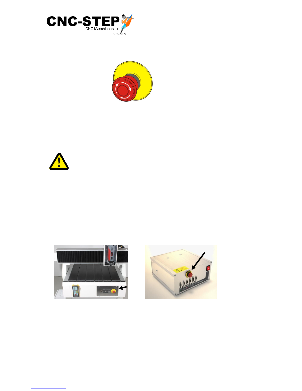
Emergency-stopbutton
Fig.1: Emergency-stop-button
By pressing the emergency-stop-button (Fig. 1) the machine is shut down by immediately switching
off the energy supply to the machine drives. After pressing the emergency-off-button, it has to be
turned to be able to turn the machine on again.
WARNING:
Danger to life when unintentional switching the machine back on!
Unintentional start-up of the machine can lead to severe injuries and death.
• Before switching on the machine make sure, that the cause of the
emergency-stop is eliminated and all safety installations are correctly
installed and functional.
• Only unlock the emergency-stop-button (Fig. 2 u. 3) when there is no risk.
Position of emergency-stop-button
Fig. 2: Emergency stop button
machine front
Fig. 3: Emergency Stop button on the stepper motor
controller (accessory)
Page 21

Operating Instructions
T-Rex-Series
CNC-STEP e.K. ▪ Siemensstrasse 13-15 ▪ 47608 Geldern ▪ Germany
Page 21
Support: +49 (0)2831/91021-50
31.03.2014
2.6.2 Sa fe t y i ns t a l la t i on s , w h i ch h a v e t o b e u p d a te d b y t h e
ow n i n g o p e r a t o r
Extraction
When processing light metal alloy such as magnesium, aluminium and titanium an extraction
system has to be installed.
HINT: Risks to human health and environment!
Wrong handling and no extraction system can cause production of particulate matter.
Particulate matter damages mostly the airways, because it gets inhaled. Following
health effects related to particulate matter concentrations are generally known:
• Temporary impairments of the repertory
• Higher medication requirements for asthma patients
• Increased hospital admissions
• Increased mortality caused by cardiovascular problems and respiratory
diseases
2.7 Behaviour in case of fire or accidents
Preventive measures
• Always be prepared for accidents or fires!
• Keep first aid facilities (first aid box, blankets etc.) and fire extinguishers accessible at all
times.
• Familiarise personnel with accident reporting, first aid and rescue equipment.
• Keep access routes clear for rescue vehicles.
Measures for fire and accidents
• Cause emergency-stop by pressing emergency-stop-button immediately.
• If there is no risk for own health, remove all persons from the danger zone.
• Instigate first aid measures, if necessary.
• Call the fire brigade and/or rescue service.
• Fire: Fight fire with fire-extinguishers, if there is no risk for own health. Continue fire-
fighting until fire-brigade arrives.
• Inform responsible persons at the place of action...
• Clear access routes for emergency vehicles.
• Instruct rescue vehicles.
Page 22

Operating Instructions
T-Rex-Series
CNC-STEP e.K. ▪ Siemensstrasse 13-15 ▪ 47608 Geldern ▪ Germany
Page 22
Support: +49 (0)2831/91021-50
31.03.2014
2.8 Environmental protection
HINT: Risk for environment caused by carelessly handled hazardous
substances!
Handling with hazardous substances can be dangerous for the environment
if handled carelessly, especially when disposed wrong. This can cause
severe damages to the environment.
• Please pay attention to the correct handling and disposal of below
mentioned hazardous substances.
• If environmentally hazardous substances are accidentally released
into the environment, take suitable measures immediately. In case of
doubt inform the responsible local authority of the damage
Lubricants
Lubricants, such as grease and oils, contain toxic substances. They must not
reach the environment. The disposal must be taken place by a specialised waste
management company.
Gear oil
Gear oil contains many toxic substances. They must not reach the environment.
The disposal must be taken place by a specialised waste management
company.
Cooling emulsion
Cooling emulsion may contain toxic and polluting substances such as glycol.
They must not reach the environment. The disposal must be taken place by a
specialised waste management company.
2.9 Signage
Following symbols and signs are found in the working area. They apply to the immediate
neighbourhood in which they are displayed.
WARNING:
Risk by illegibly signage!
Over the years stickers and signs may become dirty or defaced in any other way; so
that hazards are not recognized and necessary operating instructions have been
adhered This is a risk of severe injury!
• Always keep safety, warning and operating instructions in a well legible
condition.
• Immediately replace damaged or obliterated signs or labels.
Page 23
Operating Instructions
T-Rex-Series
CNC-STEP e.K. ▪ Siemensstrasse 13-15 ▪ 47608 Geldern ▪ Germany
Page 23
Support: +49 (0)2831/91021-50
31.03.2014
2.9.1 Ma nd a t o ry s i g ns
Take notice of instruction
Only use the machine after reading the instructions!
2.9.2 Pro h i b i ti on s ig n s
Prohibitions for people with pacemakers
In the area of this sign a strong electromagnetically field is possible, which can disturb
or disable pacemakers.
Persons with pacemakers must not stand near the machine.
Prohibition for people with metal implants
Persons with metallic implants must not be allowed in the area of the machine.
Implants can heat themselves up or be drawn-in by the electro-magnetically field.
Operation with necklace is prohibited
Risk of entrapment or entanglement in moving parts.
Take off necklaces before entering the signed area.
Operation with tie prohibited
Risk of entrapment or entanglement in moving parts.
Take off tie before entering the signed area.
Operation with long hair prohibited
Risk of entrapment or entanglement in moving parts. Persons with long hair have to
wear a hair-net or hair cover.
Page 24
Operating Instructions
T-Rex-Series
CNC-STEP e.K. ▪ Siemensstrasse 13-15 ▪ 47608 Geldern ▪ Germany
Page 24
Support: +49 (0)2831/91021-50
31.03.2014
2.9.3 Wa rn i ng s
Voltage
Ins so signed areas only skilled electricians are allowed to work.
Unauthorized people must not enter these signed working areas or open so signed
cupboards.
Automatic start
The start of the machine in production systems is indicated by a flashing light or
acoustic signal. From this moment on all works must be finished.
After signalling, leave danger zone.
Always maintain an adequate distance to all moving parts, risk of hands, hair and
clothing being drawn in.
Hot surface
Hot surfaces, such as hot machine parts, container and materials, may not always be
noticeable. Do not touch without protective gloves!
Page 25
Operating Instructions
T-Rex-Series
CNC-STEP e.K. ▪ Siemensstrasse 13-15 ▪ 47608 Geldern ▪ Germany
Page 25
Support: +49 (0)2831/91021-50
31.03.2014
2.9.4 Fire p r o t e c t i o n s i g n s
Fire alarm phone
The fire alarm phone may only be used in case of emergency.
Before fighting the fire, make an emergency call via fire alarm phone.
A fire alarm phone can be, in exception, even a simple phone that establishes a
connection via telephone directly to the fire department, the operating station or to a
person permanently present. In such cases, the following information is required:
• WHO reports?
• WHAT has happened?
• HOW MANY are affected / injured?
• WHERE has something happened?
• WAIT for questions!
Fire extinguisher
Indication of a fire extinguisher.
Before fire extinguishers are brought to the fire, warn all persons in the danger zone or
help to escape from the area. Only remove the fire extinguisher to put out a fire.
Page 26
Operating Instructions
T-Rex-Series
CNC-STEP e.K. ▪ Siemensstrasse 13-15 ▪ 47608 Geldern ▪ Germany
Page 26
Support: +49 (0)2831/91021-50
31.03.2014
2.9.5 Ex it s i g ns
First aid
The safety signs without an additional sign indicate a first-aid kit.
If further signs such as "medical station" or "first responders" are fitted, first aid
professionals are additionally available.
In case of an emergency (even for minor injuries) use the material in the first-aid kit
for first aid treatment of the injured person. When using or taking out first-aid
materials registrations must be made in the accident book.
Emergency exit
In a case of emergency, leave the danger zone through the emergency exit.
Emergency phone
In case of an emergency, use the phone to alert.
The following details shall be transmitted to the monitoring station:
• WHO is calling?
• WHAT happened?
• HOW MANY are affected / injured?
• WHERE has it happened?
• Wait for questions!
Escape
In a case of emergency, follow the suggested escape route in direction of the arrow.
Emergency evacuation routes must always be kept clear.
Page 27
Operating Instructions
T-Rex-Series
CNC-STEP e.K. ▪ Siemensstrasse 13-15 ▪ 47608 Geldern ▪ Germany
Page 27
Support: +49 (0)2831/91021-50
31.03.2014
3 Techni c a l
speci f i c a ti o ns
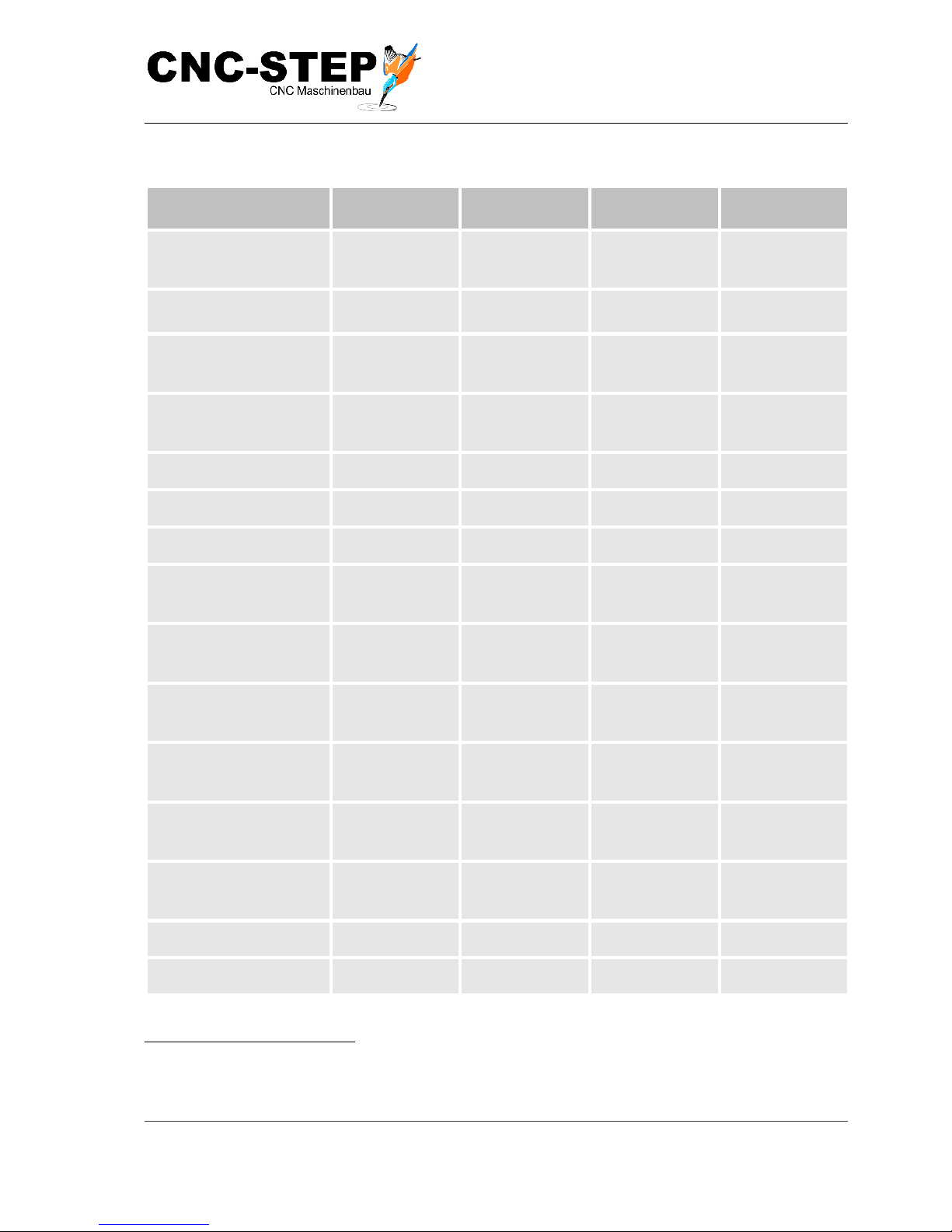
3.1 General information
Specification
T-Rex 0609
T-Rex 0712
T-Rex 1215
T-Rex 1224
Length (L)
1540 mm
1960 mm
2180 mm
3070 mm
Width (B)
1200 mm
1300 mm
1800 mm
1800 mm
Height (H)
1420 mm
1420 mm
1420 mm
1420 mm
Weight
ca. 300 kg
ca. 350 kg
ca. 400 kg
ca. 500 kg
Clamping surface
(L x B)
1300 x 780mm
1650 x 880mm
1860 x 1340mm
2800 x 1340mm
Passage height
120 mm
120 mm
120 mm
120 mm
Traversing ranges
Specifications
T-Rex 0609
T-Rex 0712
T-Rex 1215
T-Rex 1224
X-axis
900 mm
1200 mm
1500 mm
2400 mm
Y-axis
600 mm
700 mm
1200 mm
1200 mm
Z-axis
130 mm
130 mm
130 mm
130 mm
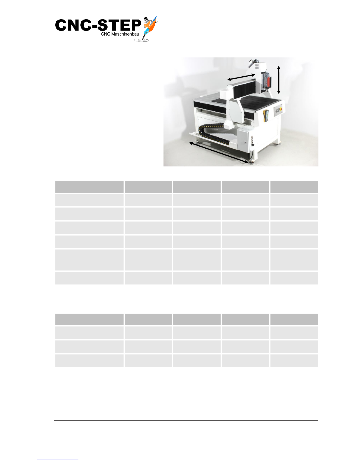
Fig. 4: T-Rex
Maschine
Z
Y
Page 28
Operating Instructions
T-Rex-Series
CNC-STEP e.K. ▪ Siemensstrasse 13-15 ▪ 47608 Geldern ▪ Germany
Page 28
Support: +49 (0)2831/91021-50
31.03.2014
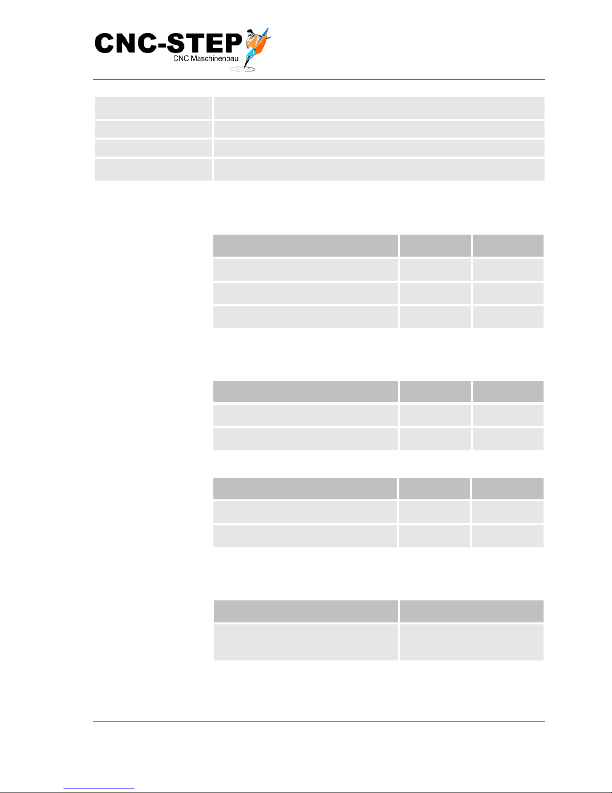
Other parameters
Specification
T-Rex 0609
T-Rex 0712
T-Rex 1215
T-Rex 1224
Positioning speed
(rapid traverse XY)
280 mm/sec1
280 mm/sec1
200 mm/sec1
200 mm/sec1
working speed (XY)
200 mm/sec1
200 mm/sec1
133 mm/sec1
133 mm/sec1
Positioning speed
(rapid traverse Z)
60 mm/sec
60 mm/sec
60 mm/sec
60 mm/sec
Positioning speed
(Rapid traverse Z)
2000
2000
2000
2000
thread pitch X
10 mm
10 mm
10 mm
16 mm
thread pitch Y
10 mm
10mm
10 mm
10 mm
thread pitch Z
5 mm
5 mm
5 mm
5 mm
Profile rail system X
HIWIN / THK
15mm
HIWIN / THK
15mm
HIWIN / THK
15mm
HIWIN / THK
15mm
Profile rail system Y
HIWIN / THK
15mm
HIWIN / THK
15mm
HIWIN / THK
15mm
HIWIN / THK
15mm
Profile rail system Z
HIWIN / THK
15mm
HIWIN / THK
15mm
HIWIN / THK
15mm
HIWIN / THK
15mm
Programmable
resolution X
0,005 mm
0,005 mm
0,005 mm
0,008 mm
Programmable
resolution Y
0,005 mm
0,005 mm
0,005 mm
0,005 mm
Programmable
resolution Z
0,0025 mm
0,0025 mm
0,0025 mm
0,0025 mm
repeatability
0,01mm
0,01mm
0,01mm
0,01mm
backlash
+- 0,015mm
+- 0,015mm
+- 0,015mm
+- 0,015mm
1
Measured in the diagonal drive X + Y (depending on contour shape)
If the speed is >120mm/sec you need the software WinPCNC USB or Profi!
Page 29
Operating Instructions
T-Rex-Series
CNC-STEP e.K. ▪ Siemensstrasse 13-15 ▪ 47608 Geldern ▪ Germany
Page 29
Support: +49 (0)2831/91021-50
31.03.2014
Drive X-axis
brushless stepper motor(brand)
Drive Y axis
brushless stepper motor(brand)
Drive Z axis
brushless stepper motor(brand)
reference switch
Meder Reed Sensors Type MK04-non-contact on all axes
3.2 Power values
Feed drive X/Y/Z
Specification
Value
Unit
Power consumption motor X.
4,5
A
Power consumption motor Y.
4,5
A
Power consumption motor Z.
4,5
A
3.3 Operating conditions
Environment
Specifications
Value
Unit
temperature range
15-30
°C
Relative humidity maximum
60
%
Duration
Specification
Value
Unit
Maximum operating time per session
100
h
Pause until the next session
2
h
3.4 Working materials
Working materials
Type
Low friction oil
Fine mechanics oil Acid and
resin free
Page 30
Operating Instructions
T-Rex-Series
CNC-STEP e.K. ▪ Siemensstrasse 13-15 ▪ 47608 Geldern ▪ Germany
Page 30
Support: +49 (0)2831/91021-50
31.03.2014
3.5 Emissions
Specification
Value
Unit
Noise emissions
ca. 50
dB(A)
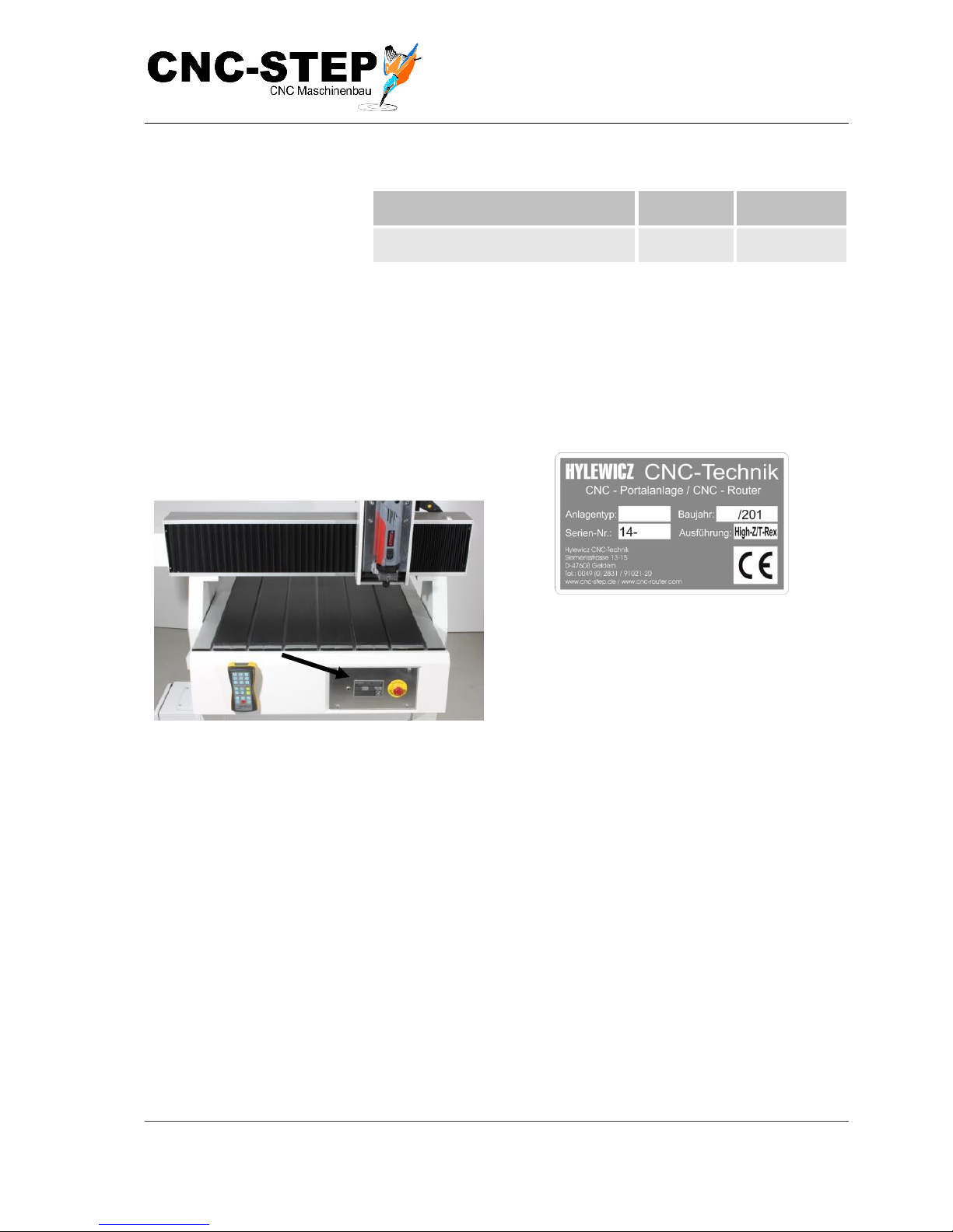
3.6 Type plate
The type plate is located on the frame of the portal system (Fig. 5 /Arrow) and includes the
following information:
Fig. 5: Location of type plate
Fig. 6: Type plate
➢ Manufacturer
➢ Type of plant
➢ Year
➢ Serial number
➢ Version
Page 31
Operating Instructions
T-Rex-Series
CNC-STEP e.K. ▪ Siemensstrasse 13-15 ▪ 47608 Geldern ▪ Germany
Page 31
Support: +49 (0)2831/91021-50
31.03.2014
4 Structure an d f u nc ti o ns
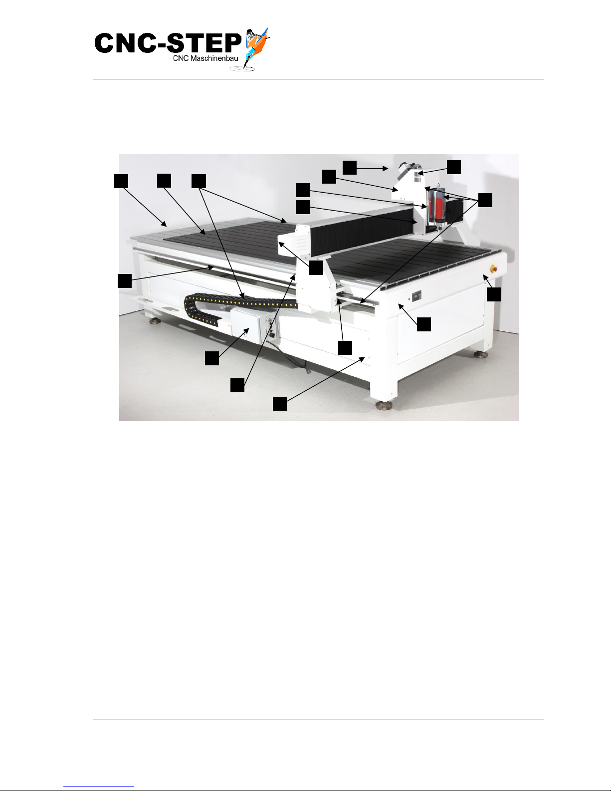
4.1 Overview
Fig. 7: Overview T-Rex
1 Stepper motor of the X-axis (under the cover)
2 Stepper motor of the y-axis (under the cover)
3 Stepper motor of the Z-axis (under the cover)
4 X-axis with carriage (Y-bridge)
5 Y-axis with carriage
6 Z-axis with carriage
7 Frame
8 Energy chain
9 Reference switch XYZ
10 Connection box for stepper motor control
11 miniXLR pin socket
12 Profile rail guides
13 Cutter motor connector
14 Tool holding fixture Holder 43H7
15 Milling motor (optional)
16 T-slot with sacrificial material
17 Emergency stop button
1
2 3 5 4 6 7 10
8
11
12
13
14
15
17
16
9
Page 32

Operating Instructions
T-Rex-Series
CNC-STEP e.K. ▪ Siemensstrasse 13-15 ▪ 47608 Geldern ▪ Germany
Page 32
Support: +49 (0)2831/91021-50
31.03.2014
4.2 Short description for the area of application
Usage of the machine
The machine is used in conjunction with a tool for:
• Milling
• Engraving
• Cutting
• Drilling
• Laser Engraving
• Grinding
• Dosing
• Measuring
• Positioning
Short Description
The machine cannot function alone. The following additional components (accessories) are
necessary for operation:
• Control which consists of a PC with the right configuration with struck up control software
(e.g. WinPCNC, Mach3, USBCNC) and a stepper motor control (e.g. Zero3).
• Tool with 43mm intake for direct clamping into the holder provided.
• Accessories, see Appendix
Control via operating software
To control it requires a CNC-CAM-software.
In a design-/graphic-program (e.g. ConstruCAM 3D, Corel Draw, AutoCad, etc.) the drawings or
texts are created and stored in a suitable format. This data can be (e.g. WIN PC-NC) read by the
control software.
Via control the stepper motors for the axis-movement are controlled. By stepping motors and the
driven ball screws, a conversion of rotary motion into linear is carried out.
Page 33
Operating Instructions
T-Rex-Series
CNC-STEP e.K. ▪ Siemensstrasse 13-15 ▪ 47608 Geldern ▪ Germany
Page 33
Support: +49 (0)2831/91021-50
31.03.2014
4.3 Module description
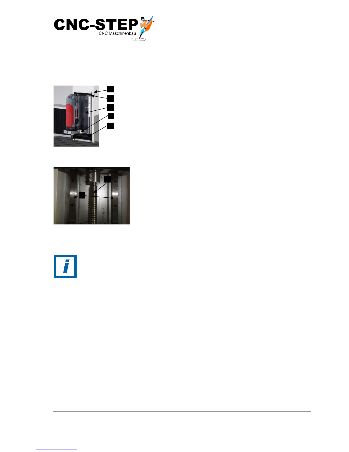
4.3.1 Z- ax i s w ith car r i a g e
Fig. 8: Z-carriage
1
Magnetic contact of the Zaxis
2
Reference switch Z-axis
3
Z-axis
4
Tool holder (43H7 recording)
5
bellow
Fig. 9: Z-carriage
1 Ball screw
2 Linear guides
The two linear guides (Fig. 9/2), lead to the inclusion of the
accessory holder. The ball screw spindle (Fig. 9/1) represents the
Z-axis on which the accessory holder with a suitable tool (43H7
recording) are moved along the Z-linear guides.
HINT:
Reference switches are required for axes without absolute position encoder to
feature in the initialization of the axis by a known reference point (zero point of the
axis). From this position, all other positions are then calculated relative to the
process of the axis via software.
Page 34
Operating Instructions
T-Rex-Series
CNC-STEP e.K. ▪ Siemensstrasse 13-15 ▪ 47608 Geldern ▪ Germany
Page 34
Support: +49 (0)2831/91021-50
31.03.2014
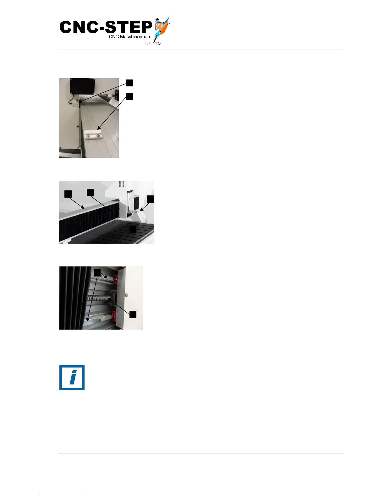
4.3.2 Y- a x i s w i th c a r r i a ge
Fig. 10: Y-Bridge
1 Reference switch Y-axis
2 Magnetic contact Y-axis
Fig. 11: Y-bridge
1 Y-bridge
2 Tool holder (43H7 holder)
3 bellow
Fig.12: Y-carriage bellow opened
1 Linear guides
2 Ball screw
The two linear guides (Fig. 12/1) and the ball screw (Fig. 12/2)
are located on the Y-bridge (Fig. 11/1) and represent the y-axis.
Along the Y-bridge the tool holder(Fig. 11/2) is moved with
suitable tool(43H7 tool holder).
HINT:
Reference switches are required for axes without absolute position encoder to
feature in the initialization of the axis by a known reference point (zero point of the
axis). From this position, all other positions are then calculated relative to the
process of the axis via software.
Page 35
Operating Instructions
T-Rex-Series
CNC-STEP e.K. ▪ Siemensstrasse 13-15 ▪ 47608 Geldern ▪ Germany
Page 35
Support: +49 (0)2831/91021-50
31.03.2014
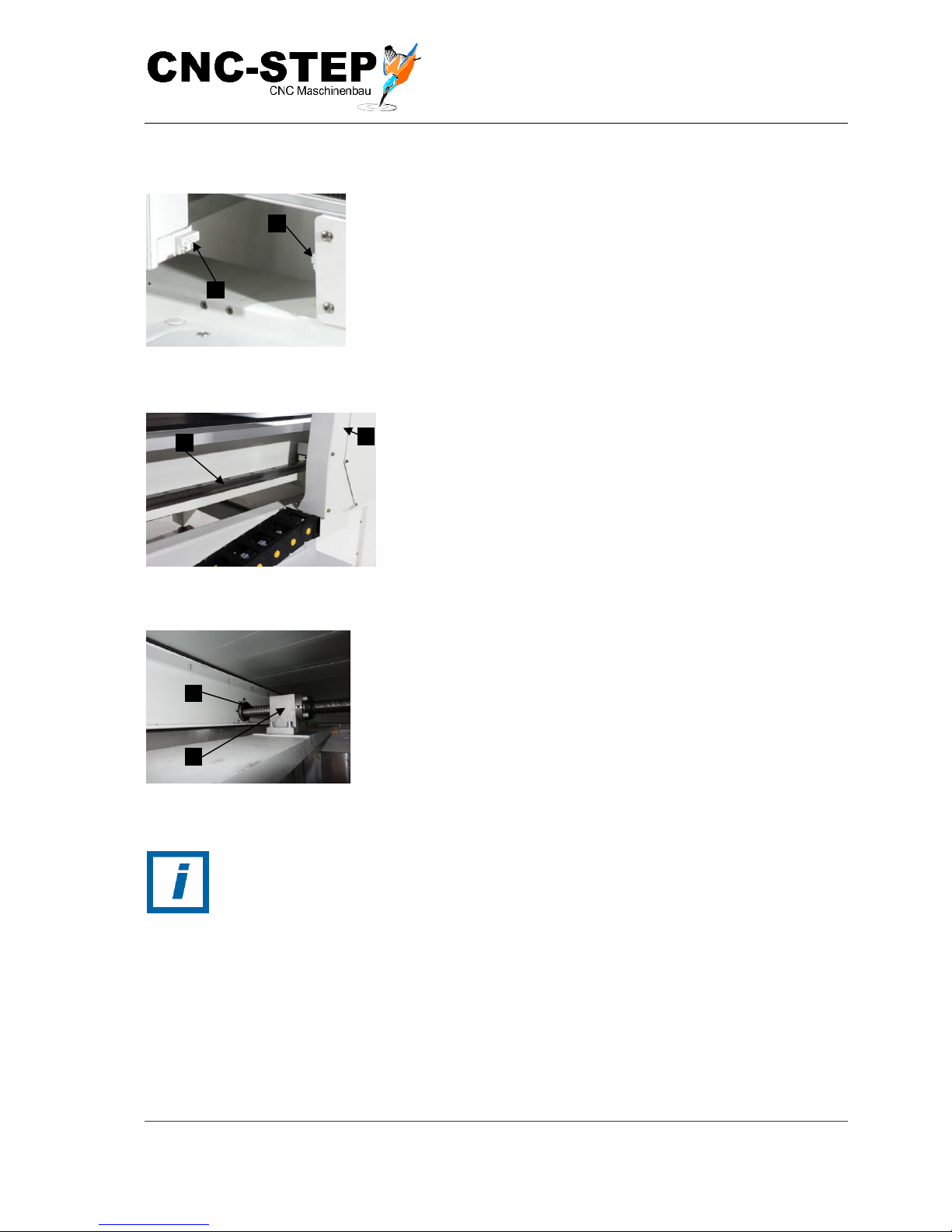
4.3.3 X-ax i s w i t h c a rr i a g e
Fig. 13: X-reference switch position
1 Reference switch X-axis
2 Magnetic contact X-axis
Fig. 14: X-carriage guide
1 Y-bridge
2 Linear guide
The Fig. shows the X-linear guide (Fig. 14/2) from one side of
the machine.
The second X-linear guide is symmetrically located on the other
side of the machine.
Fig. 15: X-carriage drive
1 Ball screw
2 Ball nut
The ball screw (Fig. 15/1) is located under the machine.
The two linear guides represent the X-axis, on which the Ybridge is moved on (Fig. 14/1) along the X linear guides.
HINT:
Reference switches are required for axes without absolute position encoder to
feature in the initialization of the axis by a known reference point (zero point of the
axis). From this position, all other positions are then calculated relative to the
process of the axis via software.
Page 36
Operating Instructions
T-Rex-Series
CNC-STEP e.K. ▪ Siemensstrasse 13-15 ▪ 47608 Geldern ▪ Germany
Page 36
Support: +49 (0)2831/91021-50
31.03.2014
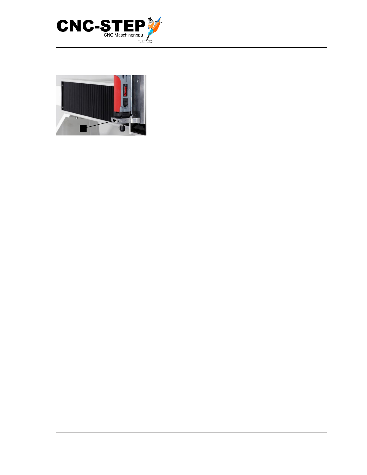
4.3.4 Too l h o l d e r
Fig. 16: Tool holder 43H7
On the tool holder of the Z-axis (Fig. 16/1)some of the most
important tools, optionally available, can be attached(see
Appendix "Accessories").
4.4 Operating elements
The machine does not have its own controls for moving the axes. This is only possible using
separate interfaces (e.g. stepper motor control Zero3)
Page 37
Operating Instructions
T-Rex-Series
CNC-STEP e.K. ▪ Siemensstrasse 13-15 ▪ 47608 Geldern ▪ Germany
Page 37
Support: +49 (0)2831/91021-50
31.03.2014
4.5 Connections
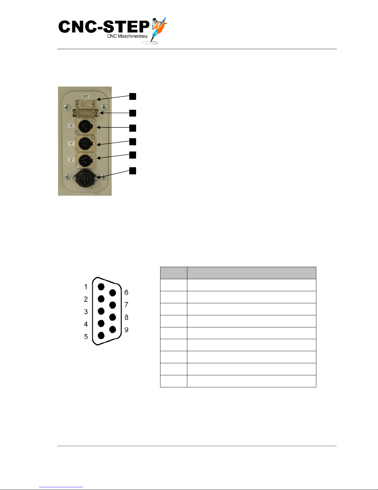
Fig. 17: Connections
The connectors of the step motor cables or control line ST are
labelled as follows:
• Connection ST emergency stop, reference switch and
socket pin 15. (Fig. 17/1)
• Motor connection C step motor, the C-axis including
the reference switch (tangential knife to the Z-axis)
(Fig. 17/2)
• Motor connection to the X-axis (Fig. 17/3)
• Motor connection of the Y-axis (Fig. 17/4)
• Motor connection of the Z-axis (Fig. 17/5)
• connector HF-spindle on the Z-axis (Fig. 17/6)
4.5.1 Cont rol si g n a l s (S T )
Fig. 18: Assignment ST connector
Sub-D
Pin Nr.
Signal
1
Limit C / Pin15 jack High-Z
2
limit X
3
limit Y
4
limit switch Z
5
Emergency stop (closed = OK, open = stop)
6
N.C.
7
N.C
8
N.C.
9
Ground, shield
Page 38
Operating Instructions
T-Rex-Series
CNC-STEP e.K. ▪ Siemensstrasse 13-15 ▪ 47608 Geldern ▪ Germany
Page 38
Support: +49 (0)2831/91021-50
31.03.2014
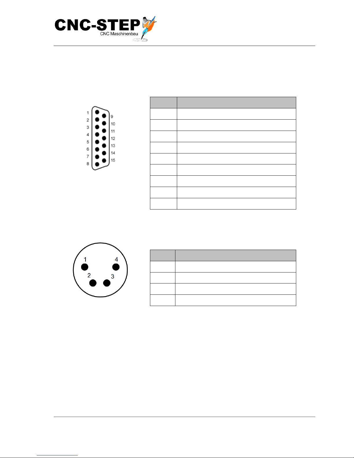
4.5.2 ro t a ti o n a x is / t a n g en t i al kn i f e ( C )
The fifth axis can optionally be used either for a rotation axis (part of set) or for a tangential knife.
Thus, this axis can be retrofitted without having to interfere with the existing wiring, all necessary
additional signals on this connector are available.
Fig. 19: Assignment of C-terminal
Sub-D
Pin Nr.
Signal
1+9
Stepper motor winding A+
2+10
Stepper motor winding A-
3+11
Stepper motor winding B+
4+12
Stepper motor winding B-
7+8
Oscillation +12 .. 24V (max. 3A)
14+15
Oscillation mass
13
limit C
5
Signal ground, screen
6
Fan, sensor +12 V max. 150mA
4.5.3 Mo to r c o n n e c t i o n ( X, Y, Z )
Fig. 20: Assignment of motor
connection
Pin No.
Signal
1
Motor winding A+
2
Motor winding A-
3
Motor winding B+
4
Motor winding B-
Page 39
Operating Instructions
T-Rex-Series
CNC-STEP e.K. ▪ Siemensstrasse 13-15 ▪ 47608 Geldern ▪ Germany
Page 39
Support: +49 (0)2831/91021-50
31.03.2014
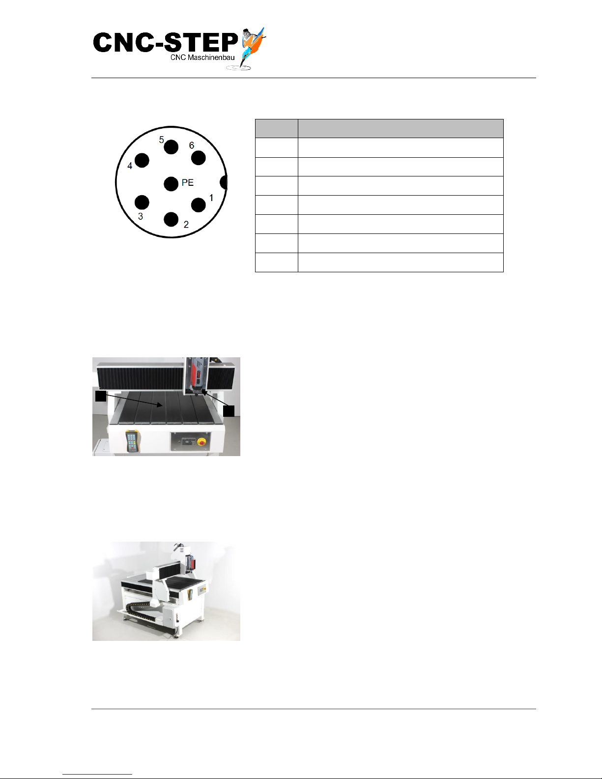
4.5.4 HF-s pi n d l e c o nn e c t i on
Fig. 21: Assignment of HF-spindle
connection
Pin No.
Signal
1
U / T1
2
V / T2
3
W / T3
4
PE / Spindle
5
N
6 L PE
Earth
4.6 Work and danger areas
4.6.1 Wo rk i ng a r e a
Fig. 22: Workspaces
• PC (Accessories)
• area of the workpiece holder (Fig. 22/1) (when turned
off)
• range of motion of the axes (Fig. 22/2) (when turned off).
In order to span workpieces.
4.6.2 Dange r zon e
Fig. 23: the danger zone
• Total area of machinery in operation
Page 40
Operating Instructions
T-Rex-Series
CNC-STEP e.K. ▪ Siemensstrasse 13-15 ▪ 47608 Geldern ▪ Germany
Page 40
Support: +49 (0)2831/91021-50
31.03.2014
5 Tra n s po rt , p a ck a ging a n d s to r ag e
HINT:
As part of the installation and the further use the operator or maintenance personnel
must be entrusted by the operator with the handling of packages. Always observe the
instructions listed below.
5.1 Safety instructions for transport
Suspended loads
WARNING:
Danger to life due to suspended loads!
When lifting operations are carried out loads can swing out and fall off. This may
lead to serious injury or death.
• Never stand under or into the swivel area of a suspended load.
• Loads are only to be moved only under supervision.
• Use only approved lifting gear and lifting gear with sufficient load-bearing
capacity.
• Do not use damaged or frayed lifting equipment such as ropes and straps.
• Lifting equipment such as ropes and straps must not be laid on sharp edges
and corners do not twist or knot.
• When leaving the workplace settle the load.
Eccentric focus
WARNING:
Risk of injury by falling or tipping packages!
Packages may have an off-centre focus. The wrong kind sling gear attachment can
tilt the packing crate and cause life-threatening injuries.
• Observe the markings and details on the focus on the package.
• Attach the crane hook so that it is directly above the centre of gravity.
• Lift cautiously and observe whether the load tilts.
Page 41

Operating Instructions
T-Rex-Series
CNC-STEP e.K. ▪ Siemensstrasse 13-15 ▪ 47608 Geldern ▪ Germany
Page 41
Support: +49 (0)2831/91021-50
31.03.2014
Improper transport
HINT:
Property damage due to improper transport!
Improper transportation can cause considerable material damage.
• When unloading delivered packages and when transporting on the
premises, proceed with caution and adhere to the symbols and instructions
on the packaging.
• When slinging the load all attachment points provided by the manufacturer
have to be used in accordance with the specifications.
• Do not remove packing until just before the installation.
5.2 Transport inspections
Check the delivery immediately on receipt for completeness and transport damage.
Proceed in case of visible damage as follows:
• Do not accept the delivery or only under reserve.
• Record the scope of the damage on the transport documents of the carrier, or on the delivery
note.
• Lodge complaint.
HINT:
Lodge a complaint for each defect, as soon as it is recognised. The claims for damage
must be filed in the lawful reclaim periods.
5.3 Packaging
Regarding packaging
The individual packages are packed according to the expected transport conditions.
Environmentally friendly material is used exclusively for the packaging.
The packing has the function of protecting the individual components against damage, corrosion,
etc., until they are finally assembled. Therefore, do not damage the packaging and only remove
immediately before installation.
What to do with packing materials
Dispose of packaging material in accordance with the respective valid laws and local regulations.
Page 42
Operating Instructions
T-Rex-Series
CNC-STEP e.K. ▪ Siemensstrasse 13-15 ▪ 47608 Geldern ▪ Germany
Page 42
Support: +49 (0)2831/91021-50
31.03.2014
Non-central centre of gravity
HINT:
Danger for environment due to improper disposal!
Packing materials are valuable raw materials and can continue to be used in many
cases or sensibly reconditioned and recycled. Incorrect disposal of packaging
materials, may lead to risks to the environment.
• Dispose packaging material environmentally friendly.
• Adhere to the valid local regulations for disposal.
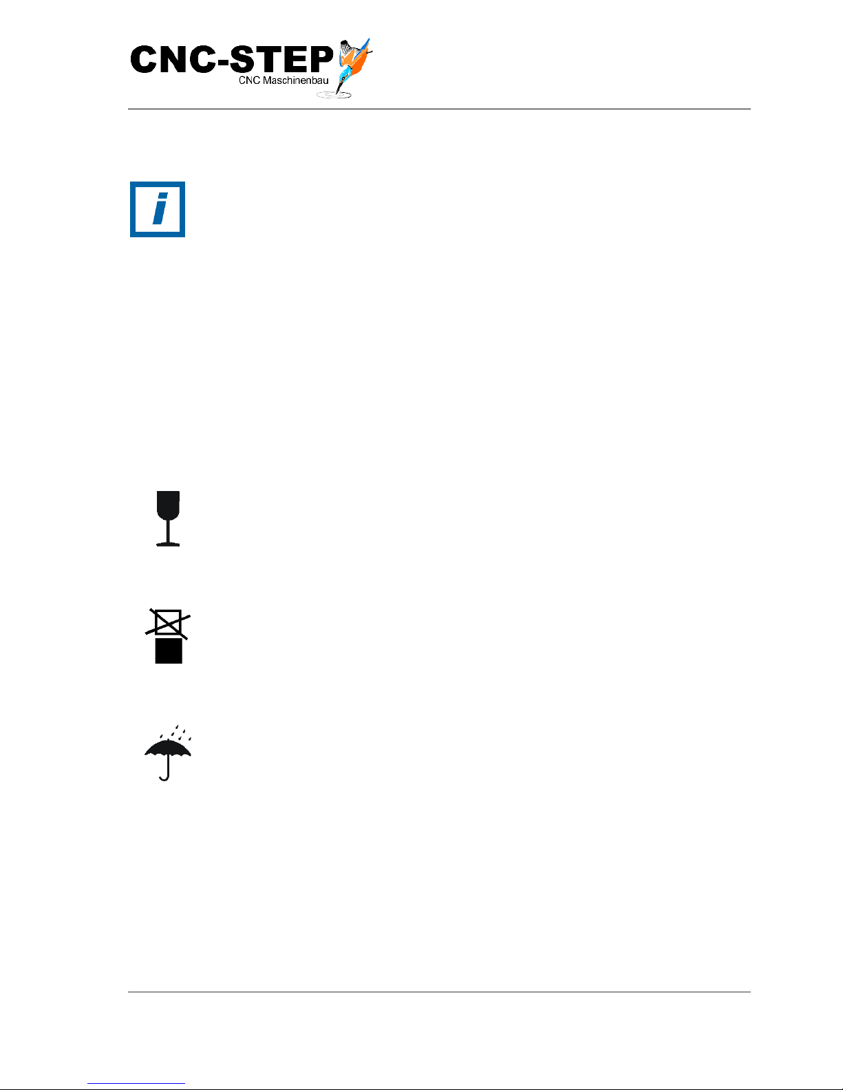
5.4 Symbols on packaging
The following symbols are shown on the packaging. Always heed the symbols during
transport.
Fragile
Identifies packages with fragile or delicate contents.
Treat the package with care, do not drop or bump it.
Do not stack
In the designated packages or goods should not be stacked.
Protect from moisture
Protect packages from moisture and keep dry.
Page 43
Operating Instructions
T-Rex-Series
CNC-STEP e.K. ▪ Siemensstrasse 13-15 ▪ 47608 Geldern ▪ Germany
Page 43
Support: +49 (0)2831/91021-50
31.03.2014
5.5 Transport
Sling points
The machine may only be transported and slinged in the frame.
Transport of pallets with the crane
Transport pieces, which are fastened on a pallet can be transported by a crane under the following
conditions:
• Crane and lifting gear must be designed for the weight of the transported items.
• The operator must be authorised to operate the crane.
Slinging
protective equipment:
• Industrial safety helmet
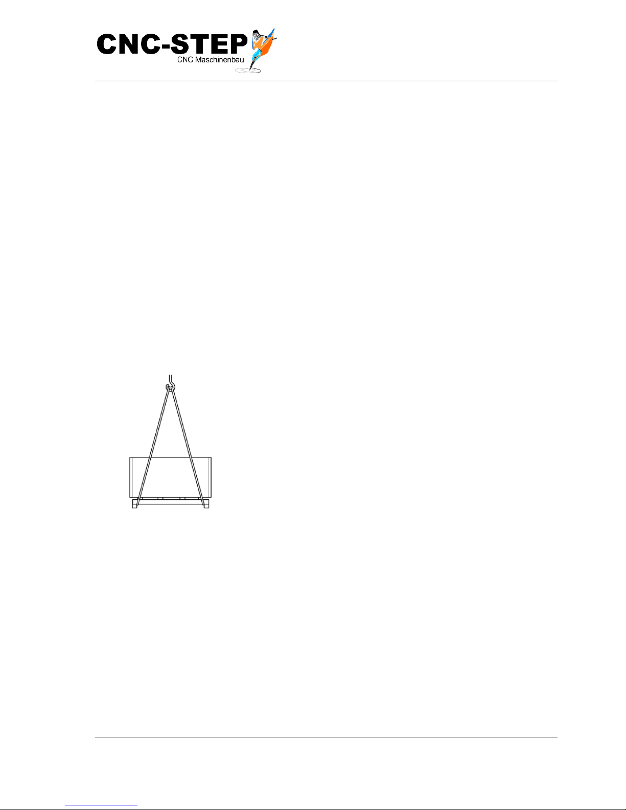
Fig. 20: lifting gear
1
Sling on ropes, belts accordingly (Fig. 20) to the pallet and
secure pallet against slipping.
2
Check whether the transport pieces are not damaged by the
slinging materials. If necessary, use other slings.
3
Make sure that the pallet with off-centre gravity cannot tip.
4
Start the transport.
Transport of pallets with a forklift
Transport pieces, which are attached to pallets can be transported under the following conditions
using a forklift:
• The fork lift must be rated for the weight of the transport pieces.
• The transport package shall be securely fastened on the pallet.
• The folk lift driver must be authorized to drive industrial trucks with driver's seat or driver's
cab according to national regulations.
Page 44
Operating Instructions
T-Rex-Series
CNC-STEP e.K. ▪ Siemensstrasse 13-15 ▪ 47608 Geldern ▪ Germany
Page 44
Support: +49 (0)2831/91021-50
31.03.2014
Transport
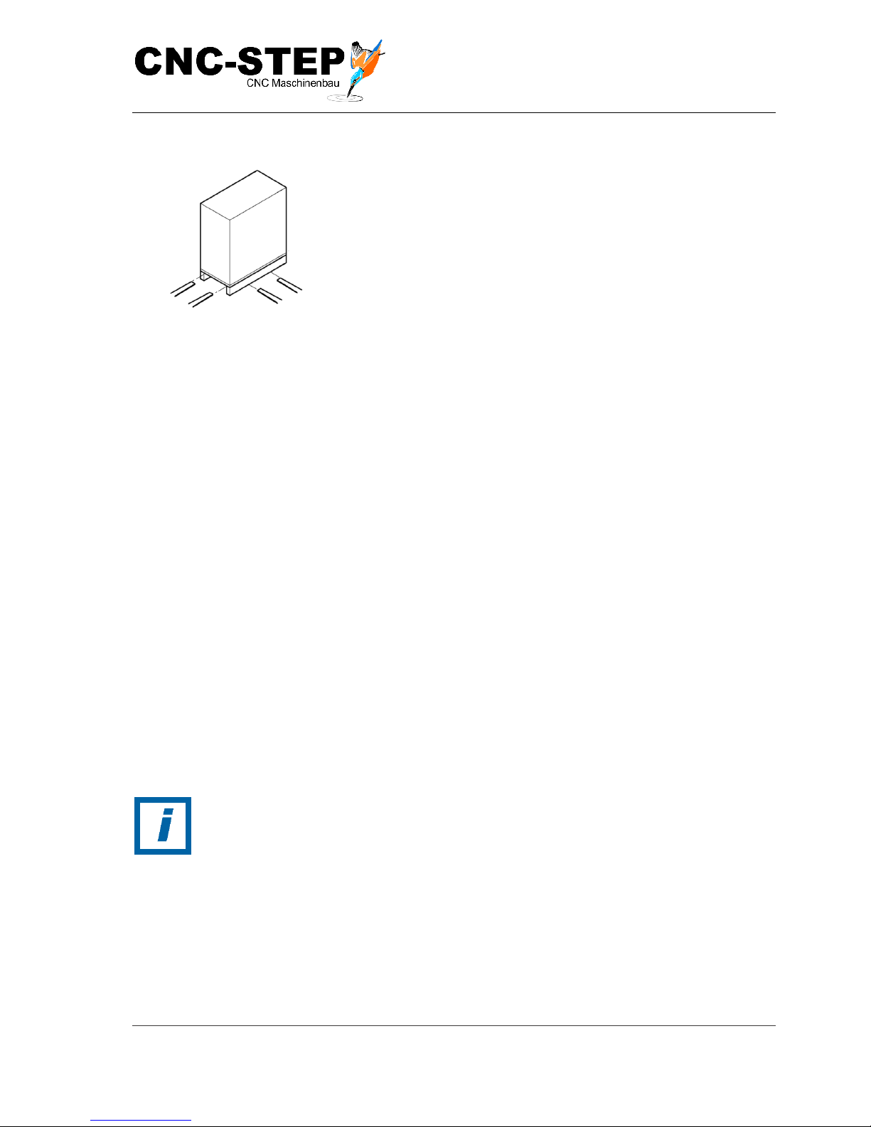
Fig. 21: Transportation by forklift
1
Drive the forklift with the forks between or the holms of
the pallet.
2
Drive the forks so far that they protrude on the opposite
side.
3
Make sure that the pallet with off-centre gravity cannot tilt.
4
Lift the pallet with transport piece and start the transport.
5.6 Storage
Storage of packages
Packages should be stored under the following conditions:
• Do not store outdoors.
• Dry and dust free.
• Not exposed to corrosive media.
• Protect from sunlight.
• Avoid mechanical shocks.
• Storage temperature: 10 to 35 ° C.
• Relative humidity: max. 60%.
For storage longer than 3 months regularly check the general condition of all parts and packaging. If
necessary, refresh or renew the preservative.
HINT:
Further instructions for storage may be found on the packaging, which go beyond
the requirements listed here. These comply accordingly.
Page 45
Operating Instructions
T-Rex-Series
CNC-STEP e.K. ▪ Siemensstrasse 13-15 ▪ 47608 Geldern ▪ Germany
Page 45
Support: +49 (0)2831/91021-50
31.03.2014
6 Inst a l l a ti o n a nd c o mm i s sionin g
6.1 Safety instructions for the installation and commissioning
Suspended loads
WARNING:
Danger to life due to suspended loads!
When lifting, loads can swing out and fall off. This may lead to serious injury or
death.
• Never stand under or into the swivel area of a suspended load.
• Loads are only to be moved only under supervision.
• Use only approved lifting gear and lifting gear with sufficient load-bearing
capacity.
• Do not use damaged or frayed lifting equipment such as ropes and straps.
• Lifting equipment such as ropes and straps must not be laid on sharp edges
and corners do not twist or knot.
• When leaving the workplace settle the load.
Improper installation and commissioning
WARNING:
Risk of injury by improper installation and commissioning!
Improper installation and commissioning can lead to severe injuries and substantial
property damage.
• Before starting any work sufficient installation freedom is required.
• Handle open, sharp-edged components with care.
• Maintain order and cleanliness at the installation site! Loosely stacked or
scattered components and tools are accident sources.
• Install components professionally. Comply with the specified screw
tightening torques.
• Secure components so they do not fall down or fall over.
• Note following guidelines before commissioning:
Ensure that all installation work in accordance with the information and
instructions were carried out and completed in this guide. Ensure that there are
no persons in the danger zone.
Page 46
Operating Instructions
T-Rex-Series
CNC-STEP e.K. ▪ Siemensstrasse 13-15 ▪ 47608 Geldern ▪ Germany
Page 46
Support: +49 (0)2831/91021-50
31.03.2014
Screw tightening torques
HINT:
Property damage caused by incorrect screw tightening torques!
All screws on the machine have been tightened before delivery to the appropriate
torque.
Additional tightening leads to undesired tensions in the machine and thus to
inaccurate machining of the work pieces.
• Tighten No screws on the machine!
6.2 Preparations
6.2.1 Ins t a l l m a c h i n e
Personnel:
• Specialist personnel
Safety equipment:
• Protective clothing
• Safety shoes
• Industrial protective helmet
ATTENTION:
Risk of injury by under-sized buildings!
Overload of ceiling structures can lead to serious damage and personal injury!
• If the machine is situated on a cantilevered building ceiling, note the
dynamic loads due to the movements.
Uneven ground
HINT:
Material damage caused by uneven ground!
Due to uneven ground deformations are caused within the machine. This results in
an imprecise machining of the work pieces.
• Place the machine on a flat and level surface.
1. Place the machine on a level, vibration-resistant surface.
2. horizontal align (Utilities water balance).
Page 47

Operating Instructions
T-Rex-Series
CNC-STEP e.K. ▪ Siemensstrasse 13-15 ▪ 47608 Geldern ▪ Germany
Page 47
Support: +49 (0)2831/91021-50
31.03.2014
6.3 Installation
6.3.1 Conn e c t i n g t h e c o m p ut e r
HINT:
The connection of the PC / computer to the stepper motor is controlled according to
the information belonging to the stepper motor controller manual.
Page 48
Operating Instructions
T-Rex-Series
CNC-STEP e.K. ▪ Siemensstrasse 13-15 ▪ 47608 Geldern ▪ Germany
Page 48
Support: +49 (0)2831/91021-50
31.03.2014
6.3.2 Conn e c t i n g t h e s t e p p er m o t o r a n d c o nt r o l c a b l e
ATTENTION:
Risk of tripping and falling!
Exposed wires on the ground can lead to tripping or slipping.
• On the ground laid cables should be covered.
• Do not lead past corners and sharp edges.
• Avoid chafing.
• Visibly mark line course.
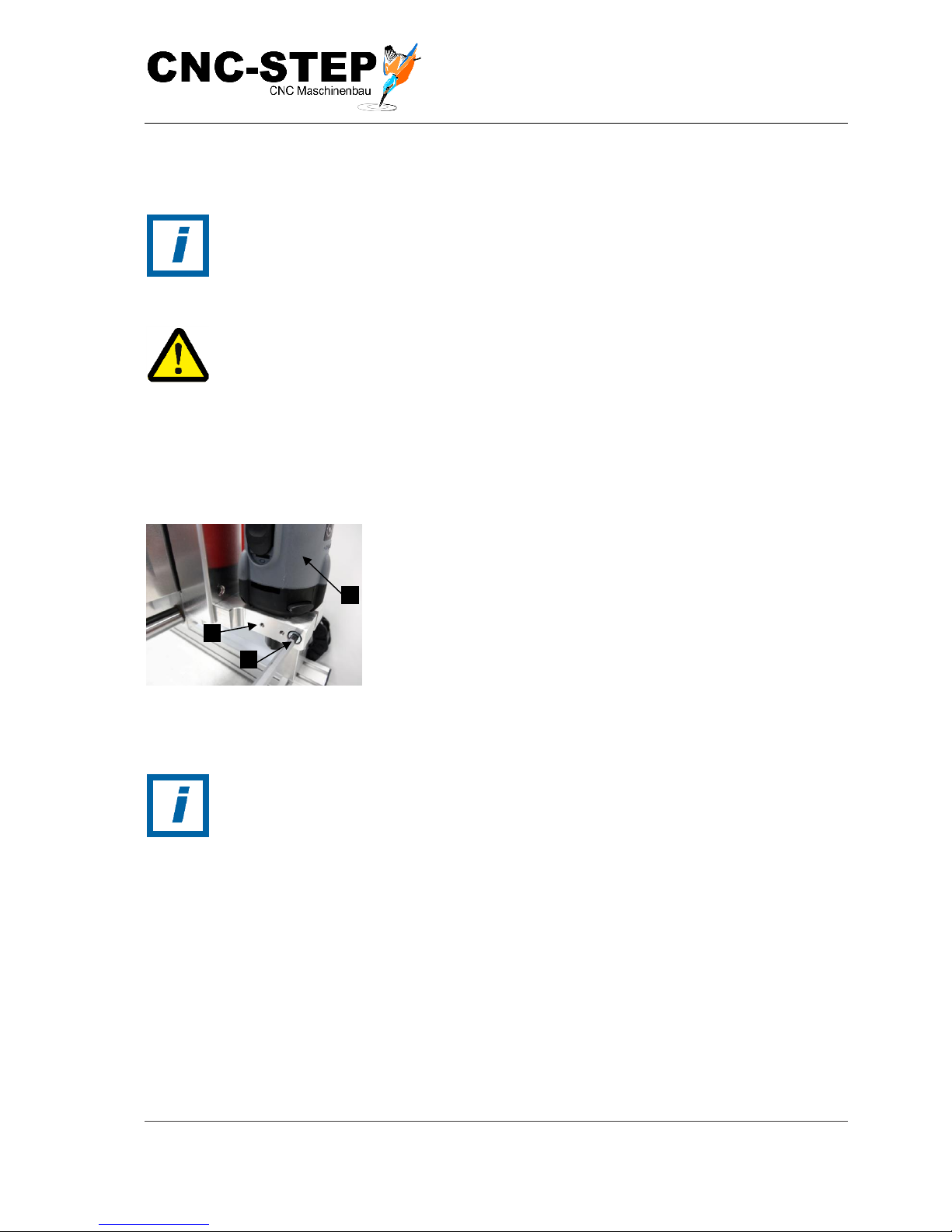
Fig. 26: Connections
The connectors of the stepping motor, and control lines (Fig. 23
/ arrow) are labelled.
Personnel:
• specialist personnel
Fig. 27: Stepper motors of axes
Connect the stepper motor and control cable with the following
assignment to the stepper motor controller:
• The port X (Fig. 27/1) of the junction box connect to
the connector X1 of the stepper motor control.
• The port Y (Fig. 27/2) connect the junction box to the
terminal Y of the stepper motor control.
• Connect the port Z (Fig. 27/3) of the connection box to
the terminal Z of the stepper motor control.
• Control line (emergency stop switch, limit and
reference switches) connect to terminal ST of the
connection-box with the ST connection of stepper
motor control.
Page 49
Operating Instructions
T-Rex-Series
CNC-STEP e.K. ▪ Siemensstrasse 13-15 ▪ 47608 Geldern ▪ Germany
Page 49
Support: +49 (0)2831/91021-50
31.03.2014
6.3.3 Ins t a l l i n g A c c e s s or i e s
HINT:
The equipment installation is carried out according to the specifications of the
accessories associated operating and assembly instructions.
WARNING:
Risk of injury due to improperly mounted accessories!
Improperly mounted accessories can lead to uncontrolled falling or throwing out
during operation and cause serious injury to skin and eyes.
• Mount accessories professionally according to the safety regulations.
Install milling motor
Personnel:
• Specialist personnel
Fig. 25: Tool holder with milling
1
Tool, for example milling motor with 43mm neck Euro
(Fig. 25/1) insert in the tool holder (Fig. 25/2) on the Z
carriage.
2
Tighten screw (Fig. 25/3) lightly until a clamping is done
3
Check milling motor for tightness in the accessory holder.
HINT:
Property damage caused by excessive tightening!
When excessive tightening the screw for mounting the milling motor, the main
bearing of the cutter motor may be damaged.
• Never tighten the screw (Fig. 25/2) for fixing the milling motor, excessively.
Only use the short side of an allen key for manual tightening!
Page 50

Operating Instructions
T-Rex-Series
CNC-STEP e.K. ▪ Siemensstrasse 13-15 ▪ 47608 Geldern ▪ Germany
Page 50
Support: +49 (0)2831/91021-50
31.03.2014
6.4 Initial start-up
Personnel:
• Specialist personnel
1
Make sure that the machine is installed and aligned.
2
Ensure that the stepper motor, and control lines are connected to the stepper motor controller
3
Make sure that the computer is connected to the stepper motor control of the machine.
4
Ensure that required accessory is installed and connected to the power supply.
5
Ensure that the appropriate software is installed on the PC.
6
Ensure the tightness of all connections.
HINT:
The individual materials have different coefficients of expansion. At an ambient
temperature of 20-25 ° C it is ensured that no significant impacts occur during
processing. Therefore, it is recommended to maintain an ambient temperature of 2025 ° C when operating the machine.
Page 51
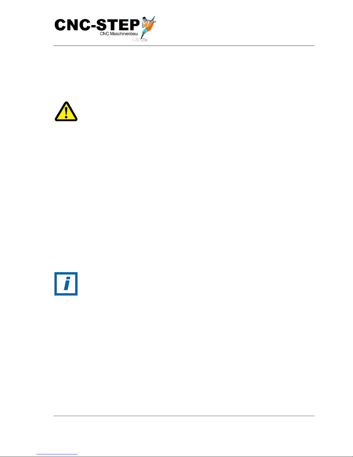
Operating Instructions
T-Rex-Series
CNC-STEP e.K. ▪ Siemensstrasse 13-15 ▪ 47608 Geldern ▪ Germany
Page 51
Support: +49 (0)2831/91021-50
31.03.2014
7 Opera t i o n
7.1 Safety guidelines for operation
Improper operation
WARNING:
Risk of injury by improper operation!
Improper operation can result in serious injuries and significant property damage.
• Perform all operations in accordance with the information and instructions of
this manual. Note the following before beginning work:
➢ Make sure that all covers and safety devices are installed and
working properly.
➢ Ensure that there are no persons in the danger zone.
• Never bridge or disable safety devices during operation.
7.2 Operations before usage
1
Make sure that all covers are installed on the machine.
2
Ensure the tightness of all connections.
3
Make sure that none of the emergency stop switch is pressed.
4
Check the ambient temperature.
HINT:
The individual materials have different coefficients of expansion. At an ambient
temperature of 20-25 ° C it is ensured that no significant impacts occur during
processing. Therefore, it is recommended to maintain an ambient temperature of 2025 ° C when operating the machine.
Page 52

Operating Instructions
T-Rex-Series
CNC-STEP e.K. ▪ Siemensstrasse 13-15 ▪ 47608 Geldern ▪ Germany
Page 52
Support: +49 (0)2831/91021-50
31.03.2014
7.3 Switching on
Personnel:
Operator
1
Turn on the computer and boot the software.
2
Clamp work piece
3
Ensure that required tool is in the tool holder, if necessary, change the tool, and see the separate
operating instructions for the accessories.
4
Ensure that no tools or other foreign objects are in the machine or system.
5
Make sure that no persons are in the danger zone.
6
Connect required accessories to the provided power supply.
7
Switch on the stepper motor control; refer to the separate operating instructions for the step
motor control.
8
Perform reference run.
9
10
Zero point determination.
Start Job.
Page 53
Operating Instructions
T-Rex-Series
CNC-STEP e.K. ▪ Siemensstrasse 13-15 ▪ 47608 Geldern ▪ Germany
Page 53
Support: +49 (0)2831/91021-50
31.03.2014
7.4 Activities during operation
7.4.1 Opera t i n g m a c h i n e
Personnel:
• Operator
Safety equipment:
• protective clothing
• Safety shoes
• Goggles
• protective gloves
• Hearing protection
• Protective cover
Rotary tools
WARNING:
Risk of injury from rotating tools!
In spindles clamped tools may result in serious personal injury or property damage.
• Before starting work, ensure that all covers and safety devices are installed
and working properly.
• • Do not reach into moving tool during operation.
• • Before replacing the tools always pull power plug of the milling motor or
turn off the machine and secure against reconnection.
Axis movements
WARNING:
Risk of injury due to axis movements!
Collision of people with components of the machine (Y-bridge, mobile unit, rotary
table with the work piece, tool) can lead to serious injuries.
• Keep anybody parts away from in-between the moving parts and end stops
of the axes.
• Do not grab in gaps between adjacent components of linear guides and
access adjacent components
• Perform work on the linear guides only at standstill.
• In the work area wear personal protective equipment.
Page 54
Operating Instructions
T-Rex-Series
CNC-STEP e.K. ▪ Siemensstrasse 13-15 ▪ 47608 Geldern ▪ Germany
Page 54
Support: +49 (0)2831/91021-50
31.03.2014
Magnetically fields
DANGER:
Danger to life due to magnetic fields!
Magnetic fields of stepper motors can cause serious injury and even death and
substantial property damage.
• Persons with pacemakers must not go near the machine itself. The function
of the pacemaker may be affected.
• People with metal implants should not be in the vicinity of the machine
itself. Implants can heat up or be attracted
• Before servicing take off metal objects (jewellery, watches, writing
instruments, etc.).
• Do not bring any electronic devices in the vicinity of the magnetic source.
These could be damaged.
• No storage media, credit cards, etc. placed in the vicinity of the magnetic
source. Data can be deleted.
Falling materials
WARNING:
Injuries caused by falling materials!
In operation, chips, tools (or parts thereof) may fall uncontrollably down or may be
thrown out and cause serious injury to skin and eyes.
• Wear face shield or fully enclosed goggles, protective clothing, gloves and
safety shoes.
• If particles enter the eye, seek immediate medical attention.
Unexpected start of the machine
WARNING:
Risk of injury from unexpected starting of the machine!
The machine and the tools may start unexpectedly, change direction or stop. Limbs
can get captured.
• Make sure that no body parts enter the danger area of the machine.
• Secure work area from accidental access.
Page 55
Operating Instructions
T-Rex-Series
CNC-STEP e.K. ▪ Siemensstrasse 13-15 ▪ 47608 Geldern ▪ Germany
Page 55
Support: +49 (0)2831/91021-50
31.03.2014
Highly inflammable substances
WARNING:
Fire hazard due to flammable materials!
Organic dusts from coal or wood or inorganic dust of magnesium, aluminium, zinc
or titanium can catch fire and cause serious or even fatal injuries.
• Within the danger zone and in the vicinity do not smoke. Do not use open
flames or sources of ignition.
• Keep fire extinguisher ready.
• • Processing of light metal alloys such as magnesium, aluminium, zinc and
titanium without suction and appropriate security measures is not allowed.
• Stop work immediately in case of fire. Evacuate danger area until the all-
clear is given.
Cooling emulsion
ATTENTION:
Risk of health damage by contact with cooling emulsion!
Contact with cooling emulsion can lead to health damage.
• Avoid skin contact.
• Remove the cooling emulsion immediately from the skin.
• Do not inhale vapours
Operation with coolant
HINT:
For more information, refer to the manufacturer's instructions of the coolant.
Page 56
Operating Instructions
T-Rex-Series
CNC-STEP e.K. ▪ Siemensstrasse 13-15 ▪ 47608 Geldern ▪ Germany
Page 56
Support: +49 (0)2831/91021-50
31.03.2014
7.4.2 Chang e t o o l
Personnel:
• Operator
Safety equipment:
• protective clothing
• Safety shoes
• protective gloves
1
Make sure that the tool (e.g. milling motor, tangential knife, etc.) is de-energized
(Connecting cable, pull out the mains plug or power button press)
ATTENTION:
Risk of burns from hot surfaces! Risk of being cut by tools and chips!
Contact with hot components can cause burns. Tools and chippings can cause injury
when touched.
- When changing tools, wear protective gloves.
2
Change tool, see the separate operating and assembly instructions
3
Make sure that the tool is again provided with voltage (connection cable, connect the power
plug or switch power button)
7.5 Switching off
1
Turn power switch on the stepper motor control to "0" or "Off"; see separate operating
instructions for the step motor control.
2
Stop software for the machine on the computer.
3
Shut down computer.
Page 57
Operating Instructions
T-Rex-Series
CNC-STEP e.K. ▪ Siemensstrasse 13-15 ▪ 47608 Geldern ▪ Germany
Page 57
Support: +49 (0)2831/91021-50
31.03.2014
7.6 Activities after use
Personnel:
• Operator
Safety equipment:
• protective clothing
• Safety shoes
• protective gloves
1.
Turning off the machine.
ATTENTION:
Risk of injury by chips!
Chips can be sharp and cause deep lacerations.
• Always wear protective gloves when removing chips.
2.
Clean the machine (see chapter 8.4.1).
7.7 Emergency Shutdown
In hazardous situations, movements of components must be stopped as soon as possible and the
power supply must be switched off.
Stopping in an emergency
1
Immediately activate emergency stop by emergency stop device.
2
If there is no danger for your health, remove persons from the danger zone.
3
If necessary, initiate first aid measures.
4
Call Fire department and / or ambulance service.
5
Inform the responsible person on site.
6
Turn the machine off and secure it against being switched on again.
7
Keep access routes for emergency vehicles free.
8
Instruct rescue vehicles.
Page 58
Operating Instructions
T-Rex-Series
CNC-STEP e.K. ▪ Siemensstrasse 13-15 ▪ 47608 Geldern ▪ Germany
Page 58
Support: +49 (0)2831/91021-50
31.03.2014
8 Main t e n a nc e
8.1 Safety Instructions for maintenance
Moving components
WARNING:
Risk of health damage by contact with cooling emulsion!
Contact with cooling emulsion can lead to health damage.
• Avoid skin contact.
• Remove the cooling emulsion immediately from the skin.
• Do not inhale vapours.
Electrical System
DANGER:
Danger to life due to electric current!
Contact with live components can be fatal. Activated electrical components can run
uncontrolled movements and cause serious injury.
• Switch off the electrical supply before starting work and secure against
reconnection.
Improperly performed maintenance
WARNING:
Risk of injury by improperly performed maintenance!
Improper maintenance can lead to severe injuries and substantial property damage.
• Before starting any work, ensure installation freedom.
• Maintain order and cleanliness at the installation site! Loosely stacked or
scattered components and tools are accident sources.
• If components have been removed, ensure correct assembly, reinstall all
fasteners and note correct screw tightening torques.
• Note following before re-starting :
➢ Ensure that all maintenance work has been done in accordance with the
information and instructions were carried out and completed in this guide.
➢ Ensure that there are no persons in the danger zone.
• Make sure that all covers and safety devices are installed and working
properly.
Page 59
Operating Instructions
T-Rex-Series
CNC-STEP e.K. ▪ Siemensstrasse 13-15 ▪ 47608 Geldern ▪ Germany
Page 59
Support: +49 (0)2831/91021-50
31.03.2014
Environmental protection
Observe the following instructions to protect the environment during maintenance:
• On all lubrication points which are supplied with lubricant by hand, remove escaping,
used or excess grease and dispose in accordance with applicable local regulations.
• Decant oils in suitable containers and dispose according to local regulations.
• Catch oil / fat-containing cloths in suitable containers and dispose according to local
regulations.
8.2 Spare parts
WARNING:
Risk of injury due to using unapproved replacement parts!
The use of incorrect or faulty spare parts can lead to hazards to personnel and
malfunction or failure of the machine.
• Only use original spare parts from the manufacturer or manufacturer-
approved replacement parts.
• If in doubt always contact the manufacturer.
Loss of warranty
The use of non-approved spare parts invalidates the manufacturer's warranty.
Obtain spare parts from authorized dealers or directly from the manufacturer.
The spare parts list is available on request.
Specify following points when ordering spare parts:
➢ Type
➢ Year built
➢ Serial no.
➢ Version
➢ Amount
➢ Identification
➢ desired delivery method (mail, cargo, sea, air, express)
➢ shipping address
Spare part orders without above information will not be considered. If no specification is made
regarding the shipping method, shipping will be at the discretion of the supplier.
Page 60
Operating Instructions
T-Rex-Series
CNC-STEP e.K. ▪ Siemensstrasse 13-15 ▪ 47608 Geldern ▪ Germany
Page 60
Support: +49 (0)2831/91021-50
31.03.2014
8.3 Maintenance Schedule
In the following sections, the maintenance is described that is necessary for optimum and troublefree operation of the machine.
If increased wear can be seen during regular inspections reduce the required maintenance intervals
according to the actual wear and tear. For questions about maintenance work and intervals, contact
the manufacturer.
Refer to the separate operating instructions, for the maintenance of the supplied
components.
Modell T-Rex
Interval
Maintenance work
To be carried out by
daily
Clean the machine
Operator
Check machine for damage and wear
technical personnel
10 hours
Oil ball screws
technical personnel
Oil the round shaft guides
technical personnel
Oil the profile rail guide
technical personnel
As required
Clean machine from the outside with a cloth
DIN 61650
Operator
Page 61
Operating Instructions
T-Rex-Series
CNC-STEP e.K. ▪ Siemensstrasse 13-15 ▪ 47608 Geldern ▪ Germany
Page 61
Support: +49 (0)2831/91021-50
31.03.2014
8.4 Maintenance
8.4.1 Clea n i n g o f t he m a ch i ne
Regular maintenance of the machine prevents sticking of moving parts.
Property damage caused by compressed air!
Pressurized air can damage the ball screws of the T series machine.
• Never use compressed air to clean the T series machine!
Personnel:
• Operator
Safety equipment:
• protective clothing
• Safety shoes
• protective gloves
1
Turn power switch on the stepper motor control to "0" or "Off"; see separate operating
instructions for the step motor control.
2
Free machine from chips.
ATTENTION:
Risk of injury by chips!
Chips can be sharp and cause deep lacerations.
• Always wear protective gloves when removing chips.
3
Free ball screws and linear guides from chips
4
Clean the entire machine with a slightly oily cloth DIN 61650
Page 62
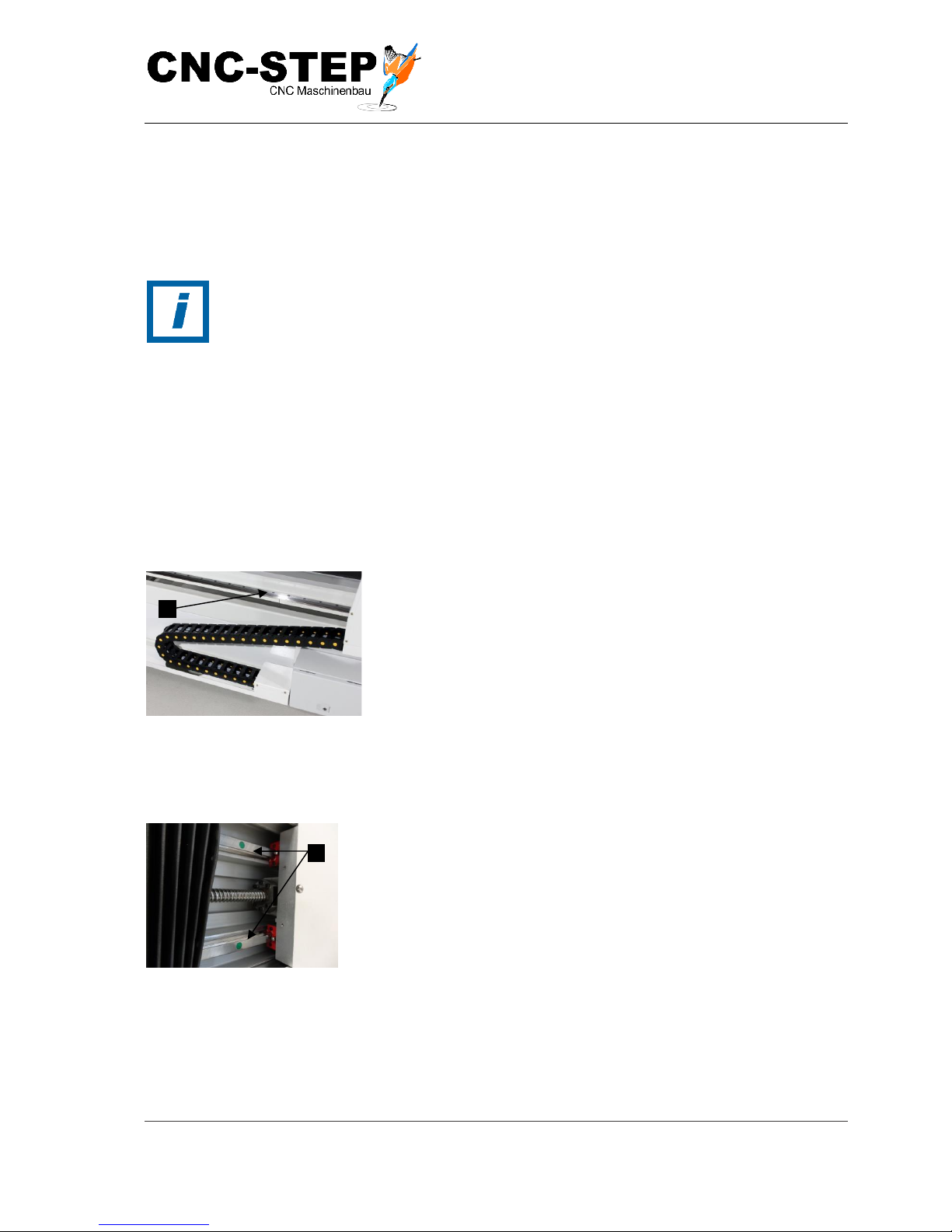
Operating Instructions
T-Rex-Series
CNC-STEP e.K. ▪ Siemensstrasse 13-15 ▪ 47608 Geldern ▪ Germany
Page 62
Support: +49 (0)2831/91021-50
31.03.2014
8.4.2 Lubri c a t e m a c h i n e
The lubricants reduce wear, protect against pollution, reduce corrosion and prolong the service life
by their properties.
For supplies, see chapter 3.4.
Oil linear guides
Personnel:
• Qualified personnel
Safety equipment:
• protective clothing
• Safety shoes
• Chemical-resistant gloves
Fig. 29: linear guides of the Xaxis
1
2
Switch off the machine and secure against re-start.
Grease the linear guides of the X-axis (Fig. 29/1), the Z-axis well
using a low-friction grease wetted cloth DIN 61650 or
alternatively apply the fat with a suitable brush.
Fig. 30: Linear guide of the Y-axis
3
Grease the linear guides of the X-axis (Fig. 30/1) well using
low-friction grease soaked cloth DIN 61650 or alternatively
apply the grease with a suitable brush.
Page 63
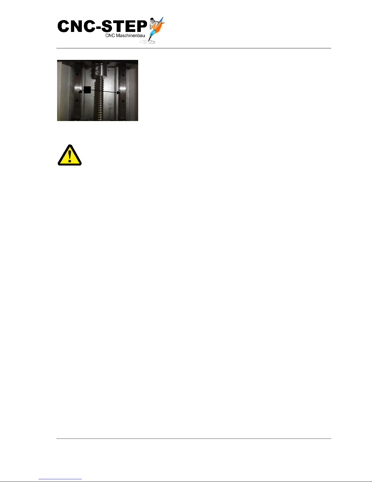
Operating Instructions
T-Rex-Series
CNC-STEP e.K. ▪ Siemensstrasse 13-15 ▪ 47608 Geldern ▪ Germany
Page 63
Support: +49 (0)2831/91021-50
31.03.2014
Fig.31: Linear guide of the Z-axis
4 Linear guides
Grease both linear guides of the Z-axis (Fig. 31/1) well using
low-friction grease soaked cloth DIN 61650 or alternatively
apply the grease with a suitable brush.
ATTENTION:
Risk of health damage by contact with oil and grease!
Contact with oil and fat can lead to health damage.
• Avoid skin contact.
• Remove Oil and grease immediately from the skin.
• Do not inhale vapours.
Grease ball screw Spindle
Personnel:
• Qualified personnel
Safety equipment:
• protective clothing
• Safety shoes
• Chemical-resistant gloves
Page 64
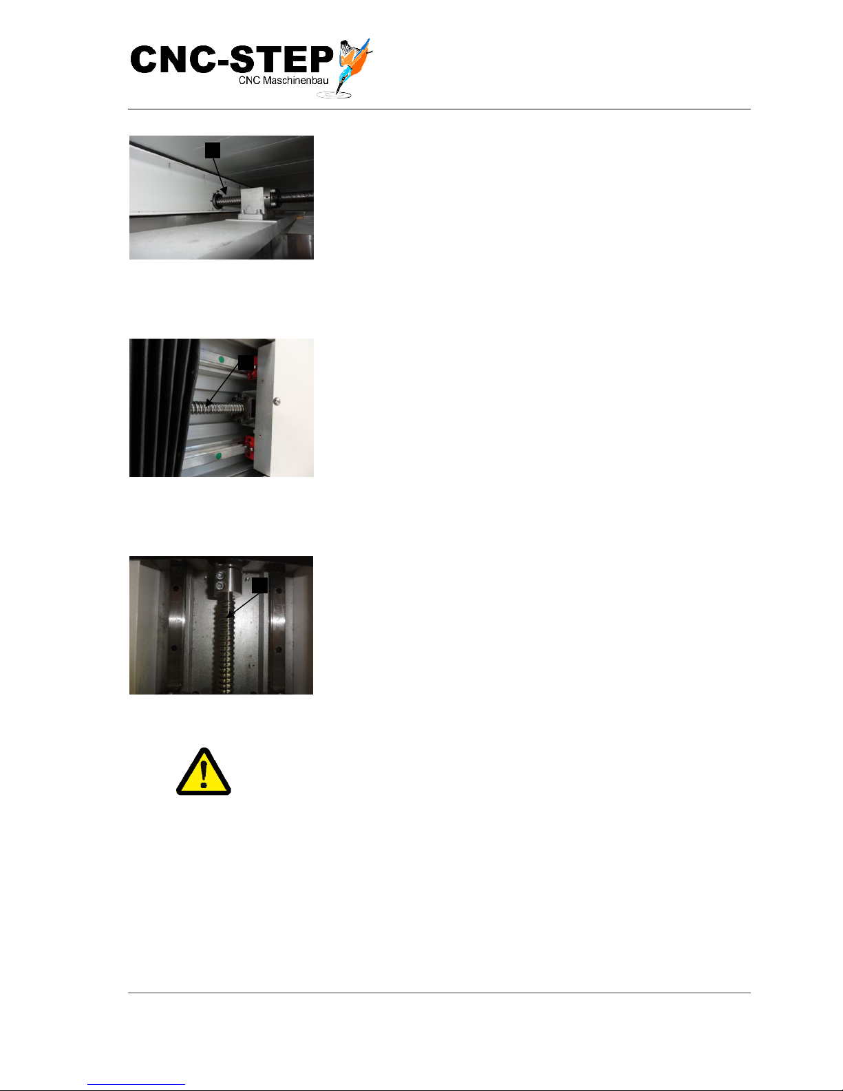
Operating Instructions
T-Rex-Series
CNC-STEP e.K. ▪ Siemensstrasse 13-15 ▪ 47608 Geldern ▪ Germany
Page 64
Support: +49 (0)2831/91021-50
31.03.2014
Fig. 32: X-drive
1 Switch off the machine and secure against restarting.
2 Ball screw (below the machine table).
Grease ball screw spindle (Fig. 32/1) with a low-friction
grease applied on a cleaning cloth DIN 61650 or alternatively
apply the grease with a suitable brush.
Fig. 33: Y-drive bellows open
3 Ball screw
Grease ball screw (Fig. 33/1) with a low-friction grease
applied on a cleaning cloth DIN 61650 or alternatively apply
the grease with a suitable brush.
Fig. 34: Z-drive bellows open
4 Ball screw
Grease ball screw (Fig. 32/1) with a low-friction grease
applied on a cleaning cloth DIN 61650 or alternatively apply
the grease with a suitable brush.
ATTENTION:
Risk of health damage by contact with oil and grease!
Contact with oil and fat can lead to health damage.
• Avoid skin contact.
• Remove Oil and grease immediately from the skin.
• Do not inhale vapours.
Page 65

Operating Instructions
T-Rex-Series
CNC-STEP e.K. ▪ Siemensstrasse 13-15 ▪ 47608 Geldern ▪ Germany
Page 65
Support: +49 (0)2831/91021-50
31.03.2014
8.5 Measures after maintenance
After completion of maintenance and before turning on the machine, perform the following steps:
1
Check all previously loosened screw connections for tightness.
2
Verify that all previously removed protective devices and covers are reinstalled correctly.
3
Ensure that all tools, materials and other equipment used were removed from the work area.
4
Clean work area and remove any spilled substances such as fluids, processing material or
similar materials.
5
Ensure that all safety devices on the machine function properly.
Page 66
Operating Instructions
T-Rex-Series
CNC-STEP e.K. ▪ Siemensstrasse 13-15 ▪ 47608 Geldern ▪ Germany
Page 66
Support: +49 (0)2831/91021-50
31.03.2014
9 Failu res
In the following chapter possible causes of interference are described and how to solve them.
With increasingly occurring disorder shorten the maintenance intervals according to the actual load.
For malfunctions that cannot be remedied by the following instructions, contact the manufacturer.
9.1 Cautions for Troubleshooting
Electrical System
DANGER:
Danger to life due to electric current!
Contact with live components can be fatal. Activated electrical components can run
uncontrolled movements and cause serious injury.
• Before starting work, switch off electrical supply and secure against
reconnection.
Moving components
WARNING:
Danger of injury by moving parts!
Rotating and / or linearly moving parts can cause severe injury.
• Before starting maintenance on movable components, turn off machine and
secure against reconnection. Wait until all parts have come to a standstill.
• In hazardous area wear tight-fitting protective clothing with low tensile
strength
Page 67
Operating Instructions
T-Rex-Series
CNC-STEP e.K. ▪ Siemensstrasse 13-15 ▪ 47608 Geldern ▪ Germany
Page 67
Support: +49 (0)2831/91021-50
31.03.2014
Improperly executed fault elimination
WARNING:
Risk of injuries caused by improper fault elimination!
Improperly performed work and troubleshooting can cause serious injury and
considerable damage to property.
• Before starting any work sufficient installation freedom has to be given
• Maintain order and cleanliness at the installation site! Loosely stacked or
scattered components and tools are accident sources.
• • If components have been removed, ensure correct assembly, reinstall all
fasteners and tighten with screw tightening torques.
Note the following before restarting:
➢ Ensure that all work and troubleshooting according to the information and
instructions in this manual have been carried out and completed.
➢ Ensure that there are no persons in the danger zone.
➢ Ensure that all covers and safety devices are installed and working
properly.
Response to malfunctions
1
For malfunctions that constitute an immediate danger to persons or property, immediately
initiate emergency stop
2
Determine cause of malfunction.
3
If the troubleshooting requires work in the danger area, turn off the machine and secure against
reconnection. Inform responsible about disorder immediately
4
Depending on the type of disorder this can be eliminated by authorized personnel.
The fault table listed below provides information about who is entitled to eliminate
the fault.
Page 68
Operating Instructions
T-Rex-Series
CNC-STEP e.K. ▪ Siemensstrasse 13-15 ▪ 47608 Geldern ▪ Germany
Page 68
Support: +49 (0)2831/91021-50
31.03.2014
9.2 Problem resolution
description of the
error
Cause
Remedy
Personnel
Machine has no
function
Emergency stop button
has been pressed
Cancel the emergency
stop
Operator
Toggle Signal is missing
See pin assignment in
software
qualified
personnel
Control cable broken
repair
Manufacturer
Stepper motor stands
Stepper motor (X, Y and
/ or Z-axis) is overloaded
Check connecting line if
required, check control,
see separate instructions
of the controller.
qualified
personnel
step loss
Stepper motor of the Xaxis (X1 and / or X2) is
overloaded
Check machine
perpendicularity
qualified
personnel
Travel speed too high
Correct the setting in
software
Operator
Cracking or loud noise
when driving the axes
PCI-interface/Parallel
port is defective
Stop the operation and
contact manufacturers
manufacturer
Lack of maintenance
Lubricate spindle waves
Operator
Hard lock error
occurred
USB dongle was not
found (WIN PC-NC
Economy)
Check the USB dongle
for proper connection
Operator
Real-time module is
blocked
On Windows, other
programs are still
running in the
background
Close programs in the
background of Windows
Operator
Energy saving mode for
the USB port is active
Disable power saving
mode in the BIOS
qualified
personnel
Page 69

Operating Instructions
T-Rex-Series
CNC-STEP e.K. ▪ Siemensstrasse 13-15 ▪ 47608 Geldern ▪ Germany
Page 69
Support: +49 (0)2831/91021-50
31.03.2014
If a disorder in the fault table is not included, please contact Customer Service. See
the separate operating instructions regarding the correcting of fault of the supplied
components.
Machine travels a
short distance and
stops abruptly
USB dongle is not
inserted properly or not
at all
Check the USB dongle
for correct fit
Operator
Machine jammed and
cannot be moved
Lack of care and
maintenance
Clean, re-lubricate if
necessary repair by
manufacturer
Operator /
manufacturer
Machine does not
recognize the reference
switch
Feed homing in software
incorrectly set
Set guideline 5mm/sec in
software
qualified
personnel
Reference switch is
defective
Replacement or repair
Personnel /
Manufacturer
Page 70
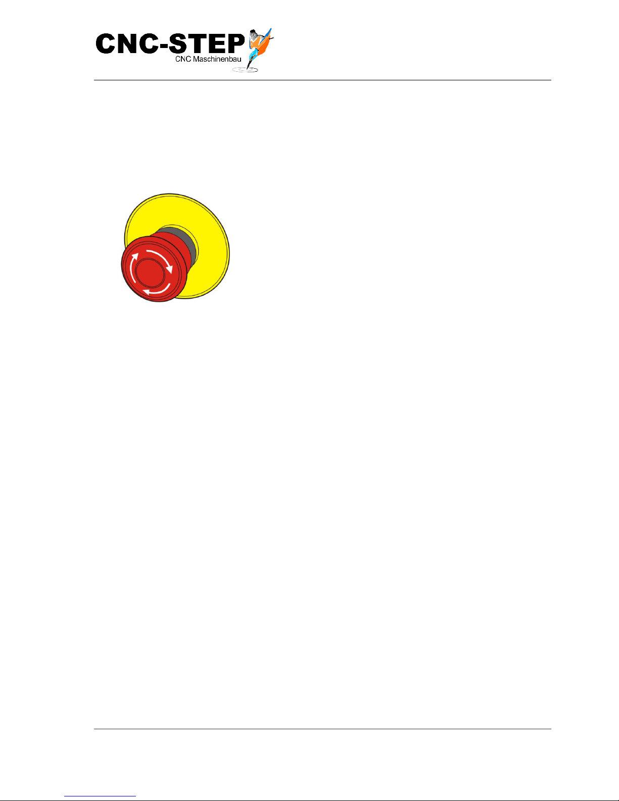
Operating Instructions
T-Rex-Series
CNC-STEP e.K. ▪ Siemensstrasse 13-15 ▪ 47608 Geldern ▪ Germany
Page 70
Support: +49 (0)2831/91021-50
31.03.2014
9.3 Problem resolution
9.3.1 Canc e l t h e em e r g e nc y s to p
Personnel:
• Operator
Fig. 34: Emergency stop button
1 Determine and remedy the fault cause.
2 Unlock the emergency stop button by turning (Fig. 34)
twice.
9.4 Commissioning after fault has been rectified
Perform the following steps to restart after correcting the fault:
1
Reset the emergency stop devices.
2
Acknowledge the fault of the control.
3
Make sure, that nobody is sure no persons in the danger zone.
4
Start according to the instructions in chapter "Operation".
Page 71
Operating Instructions
T-Rex-Series
CNC-STEP e.K. ▪ Siemensstrasse 13-15 ▪ 47608 Geldern ▪ Germany
Page 71
Support: +49 (0)2831/91021-50
31.03.2014
10 Disma n t li n g a n d dispo s a l
Once the maximum lifetime of the machine is reached, the machine must be dismantled and
environmentally friendly disposed.
• Disassembly should only be performed by qualified personnel.
• Work on the electrical system may only be performed by qualified electricians.
10.1 Safety regulations for the disassembling and disposal
Improper disassembling
WARNING:
Risk of injury from incorrect disassembly!
Residual stored energies, angular components, peaks and corners on or in the
machine or on the required tools can cause injury.
• Before starting any work ensure sufficient space.
• Take care with sharp-edged components.
• Maintain order and cleanliness in the workplace! Loosely stacked or
scattered components and tools are accident sources.
• Disassemble components professionally. Note partially high weight of the
components. If necessary, use lifting equipment.
• Secure components so they do not fall down or fall over.
• •If in doubt consult the manufacturer
10.2 Disassembling
Before beginning with dismantling:
• Switch off the machine and secure against restart.
• Discharge all power supply from the machine, physically separate stored residual energy.
• Remove the operating and auxiliary materials and residual processing materials and dispose
environmentally friendly.
Then clean modules and components in a professional manner and in accordance with applicable
local safety and environmental regulations.
Page 72

Operating Instructions
T-Rex-Series
CNC-STEP e.K. ▪ Siemensstrasse 13-15 ▪ 47608 Geldern ▪ Germany
Page 72
Support: +49 (0)2831/91021-50
31.03.2014
10.3 Disposal
If no return or disposal agreement has been made, select dissected components for recycling:
• Scrap metals.
• Plastic items for recycling.
• Other components dispose sorted by material nature.
HINT:
Threat to the environment due to improper disposal!
Incorrect disposal may cause environmental hazards may.
• electrical scrap, electronic components, disposal of lubricants and other excipients
must be carried out by authorized companies.
• If in doubt obtain information on environmentally responsible disposal at the local
municipal authority or specialized disposal companies.
Page 73

Operating Instructions
T-Rex-Series
CNC-STEP e.K. ▪ Siemensstrasse 13-15 ▪ 47608 Geldern ▪ Germany
Page 73
Support: +49 (0)2831/91021-50
31.03.2014
11 Appen d i x
11.1 Accessories
For the machine, there is a wide variety of applications.
Here is an excerpt from our catalogue of comprehensive range of accessories:
Machine extensions
- Enclosures, sub-racks, power arms,
- T-slot plates, T-slot plates on head frame
Work holding
- Vacuum tables and pumps, clamps, nuts
Tools milling, engraving, drilling
- Spindles, tool change spindles, collets, etc.
- Cutter for many different applications and materials, engraving, drill
- Axes of rotation and jaw chuck, depth sensor, tool length sensor, suction, minimum
quantity lubrication etc.
Tools for various applications
- Tangential cutting (oscillating or fixed)
- grooving module
- Laser engraving unit
- Laser scanning unit
- Plasma torch
- GranitoGrav (module for stone engraving)
Hardware and Software
- PC's and Monitors
- Radio remote control
- CAD / CAM software, font packs, specialized software
If interested, please contact our Customer Service by email or phone.
We will be pleased to advise you and give you an exact offer for your requirements!
Numerous suggestions and information is also available on our website.
Page 74
Operating Instructions
T-Rex-Series
CNC-STEP e.K. ▪ Siemensstrasse 13-15 ▪ 47608 Geldern ▪ Germany
Page 74
Support: +49 (0)2831/91021-50
31.03.2014
12 Custo m e r S e r vi ce
For technical information, please contact our Technical Customer Service:
Address:
CNC-STEP e.K.
Siemensstraße 13-15
D-47608 Geldern
Phone:
+49 (0)2831/91021-50
(Mo. - Fr. 07.00 - 15.00 Uhr)
Mobile:
+49 (0)2831/91021-20
Only in urgent cases
(Mo. - Do. 15.30 - 18.00 Uhr)
Fax:
+49 (0)2831/91021-99
E-Mail:
Web:
https://www.cnc-step.de/en
If you have questions, please contact our customer service via e-mail or phone.
We advise you gladly.
Numerous suggestions and information can be found on our website:
https://www.cnc-step.de/en
 Loading...