

CNCroom MB3 Owner's Manual

MachBob3 (MB3)
Owner’s manual
Doc E1.3R2 (3/31/2019)
for PCB V1.3
www.CNCRoom.com Page 1

Table of Contents
Introduction .................................................................................................................................................................. 4
Specification and Features ............................................................................................................................................. 4
Precaution ..................................................................................................................................................................... 5
Quick Reference ............................................................................................................................................................ 6
MB3 Layout ................................................................................................................................................................... 7
ESS and MB3 piggyback ................................................................................................................................................. 8
MB3 Connection Diagram .............................................................................................................................................. 9
Hardware .................................................................................................................................................................... 10
Connecting the ESS to Your PC ............................................................................................................................................ 10
Power Supply ....................................................................................................................................................................... 12
Axis Connection X, Y, Z, A, B, C ............................................................................................................................................ 13
Inputs ................................................................................................................................................................................... 14
Input Type ....................................................................................................................................................................... 15
Basic input connection with switches ............................................................................................................................. 15
Sensors ............................................................................................................................................................................ 17
MPG / Encoder ................................................................................................................................................................ 18
AC input ........................................................................................................................................................................... 18
Outputs ................................................................................................................................................................................ 18
Transistor Sink Output .................................................................................................................................................... 18
Relays .............................................................................................................................................................................. 19
Charge Pump ................................................................................................................................................................... 19
Analog ............................................................................................................................................................................. 20
Small Adjustment ........................................................................................................................................................ 21
Full Adjustment........................................................................................................................................................... 21
OSSD Output and Safety Circuit ...................................................................................................................................... 22
Modification ........................................................................................................................................................................ 23
Solder Bridges ................................................................................................................................................................. 23
[*1]. DC Converter ...................................................................................................................................................... 23
[*2]. Safety Circuit Inputs ........................................................................................................................................... 24
[*3]. CP override ......................................................................................................................................................... 24
[*4]. Off Delay timer ................................................................................................................................................... 24
[*5]. Input sub common ............................................................................................................................................. 25
[*6]. 5V input tolerance .............................................................................................................................................. 25
[*7]. K3 Relay pin select .............................................................................................................................................. 25
[*8]. Analog pin select ................................................................................................................................................ 26
[*9]. Isolated Outputs ................................................................................................................................................. 26
[*10]. Free Terminals .................................................................................................................................................. 27
Software ...................................................................................................................................................................... 27
Mach3 Configuration ........................................................................................................................................................... 27
Menu Config > Ports and Pins ......................................................................................................................................... 29
Menu Config > Motor Tuning .......................................................................................................................................... 32
www.CNCRoom.com Page 2

Menu PlugIn Control > Main Config: ............................................................................................................................... 34
Menu PlugIn Control > Spindle, THC & Laser Config: ...................................................................................................... 34
Mach4 Configuration ........................................................................................................................................................... 35
Setting up new profile ..................................................................................................................................................... 36
ESS configuration ............................................................................................................................................................ 37
Mach4 own configuration ............................................................................................................................................... 43
Mach4 Keyboard config .................................................................................................................................................. 52
Appendix I MB3 Specifications ..................................................................................................................................... 53
Appendix II MB3 Board Dimensions ............................................................................................................................. 53
Appendix III Safety circuit options ................................................................................................................................ 54
Safety Circuit 1 .................................................................................................................................................................... 54
Safety Circuit 2 .................................................................................................................................................................... 55
Safety Circuit 3 .................................................................................................................................................................... 56
Appendix IV Figure and Table references ..................................................................................................................... 57
Figures ................................................................................................................................................................................. 57
Table .................................................................................................................................................................................... 60
www.CNCRoom.com Page 3

Introduction
It is perhaps well understood that in an industrial environment, personal computers, motion
control boards and logic signals can face a large amount of interference from things such as
power cables, motors, welding machines, magnetic contactors etc.
We can help to minimize the effects of this interference by having any susceptible electronics
enclosed in a metal control cabinet and using the correct safety and best practice techniques,
which include, but are not limited to the installation of noise reduction such as an isolated
transformer and noise filters.
While these things will help us achieve a better result, using a control board designed for
industrial applications can be more important.
MachBob3 (MB3) is designed for industrial application and specifically to work with the Ethernet
Smooth Stepper (ESS) which is an excellent motion control board designed to be used with
Mach3 and Mach4
Specification and Features
• By using an Ethernet connection, the ESS is far more noise resistant than when using a USB or
parallel Port connection and therefore helps to protect the logic signal when the controller
and drives are located a large distance from the computer.
• Runs on Mach3 / Mach4 with Windows XP, Win7, Win8 and Windows10 both 32 and 64 bit, on
both desktop and notebook computers.
• New! Utilizes All 3 ports of the ESS.
• The Motion Command Signal can be selected between Pulse/Sign, CW/CCW, and Quadrature.
Frequency can be selected from 32 kHz to 4 MHz
• New! Differential line driver for motion signals allows for longer wiring with more resistance to
interference when compared to TTL open end.
• New! A single 24Vdc Power Supply is needed. There is a 5Vdc isolated and non-isolated dc2dc
converter on board, thus saving installation space and wiring.
• New! OSSD (Output Signal Switching Device) outputs and safety circuit are implemented when
a peripheral device such as a servo motor drive or a spindle VFD (Variable Frequency Drive)
trigger an alarm condition, which causes the Safety Circuit to disengage the OSSD output. This
method is used on large CNC machines to cut power from the drives.
• New! status LEDs for all inputs and outputs including motion control signals. Makes it much
easier to diagnose and troubleshoot.
• Isolated power and ground between the PC, ESS and I/O, which eliminates crossover noise and
ground loop problems.
• Polarity and over voltage protection (in conjunction with a fuse) for the 24Vdc power supply.
• New! “AnaSpeed2”is a 0-10V precise analog output circuit has been implemented. This small
circuit island is electrical isolated from the rest of the board, but it forms itself as part of VFD
www.CNCRoom.com Page 4

input circuit which receives PWM signal from ESS by using light. It also has on board isolated
DC2DC module which able to supply 0-10V to VFD continuously.
• A charge-pump signal is provided. This helps the user to form a safety interlock condition
between controller and devices.
• New! 18 Universal isolated fast inputs on port 1 and 2. They can be used as NPN and PNP
inputs, also able handle both 5V and 24V. (see Appendix I MB3 Specifications)
• New! 5 Universal isolated super-fast inputs on port 3. They can be used as NPN and PNP
inputs, also able handle both 5V and 24V. (see Appendix I MB3 Specifications)
• 14 NPN isolated output terminals capable of sinking current up to 70mA for each channel and
up to 500mA per group.
• New! - 3 onboard relays with both NO/NC contacts and 2 of them can select “Off Delay Time”,
which can be used for such application as “Z Drop Protection.”, Please see it on page 24 [*4].
Off Delay timer
• The K3 Relay can be controlled by a charge pump signal. Please see it on page25, [*7]. K3
Relay pin select
• New! The Raspberry Pi tall headers are used for firm connection between ESS and MB3 board.
.
. Showing the appropriate solder bridge for modification.
This allows ESS to be mounted on MB3 directly without any ribbon cables. This makes the ESS
easier to install and reduces the number of contact points, signals trace distance, inductance
and resistance between ESS and MB3 board. As a result, all signals are less likely to be affected
by noise and distortion.
• Spring terminals for quicker connecting and disconnecting of cables. They are resistant to
vibration, so no more screws which have rattled loose and no more forgetting to tighten.
Precaution
• Remember to static discharge before touching any part of ESS/MB3. Ground your body
by wearing a grounding strap or frequent touching an earthed metal chassis to release
electrostatics.
• Make sure that there is no high voltage leak from your soldering iron when soldering
the solder-bridge – the safest way is to unplug your soldering iron from the mains
power when it has reached a high enough temperature to melt the solder. High voltage
leakage from a cheap soldering iron can potentially damage the integrated circuit (IC)
on the MB3 board.
• The MB3 board is Fragile, do not drop, as it could badly damage the electronics.
• In certain circumstances, it could be possible for the MB3 board to build up excessive
heat if many of the inputs and outputs are active at same time over an extended
period. It is therefore advisable to install a good quality cooling fan to ventilate the
cabinet.
• 24V, 3A Switching power supply is recommended for powering the MB3 board. In case
of accidentally reversal power lead. The switching power supply will stop working.
There is no harm to any component of the board. However, the fuse will be blown or
even damage to the board if high current switching power supply being used.
www.CNCRoom.com Page 5
Quick Reference
Power Supply
24
Vdc
Drive
*Output can sink current up to
70 mA
L
L
LLL
L
LLLLLLL
Shrinkage part
24V
0V
Common 0V for PNP inputsCommon 24V for NPN inputs
NO, NC contacts x3
VFD
Inverter
A-IN
0V
<< Two types of wiring are
given as an example.
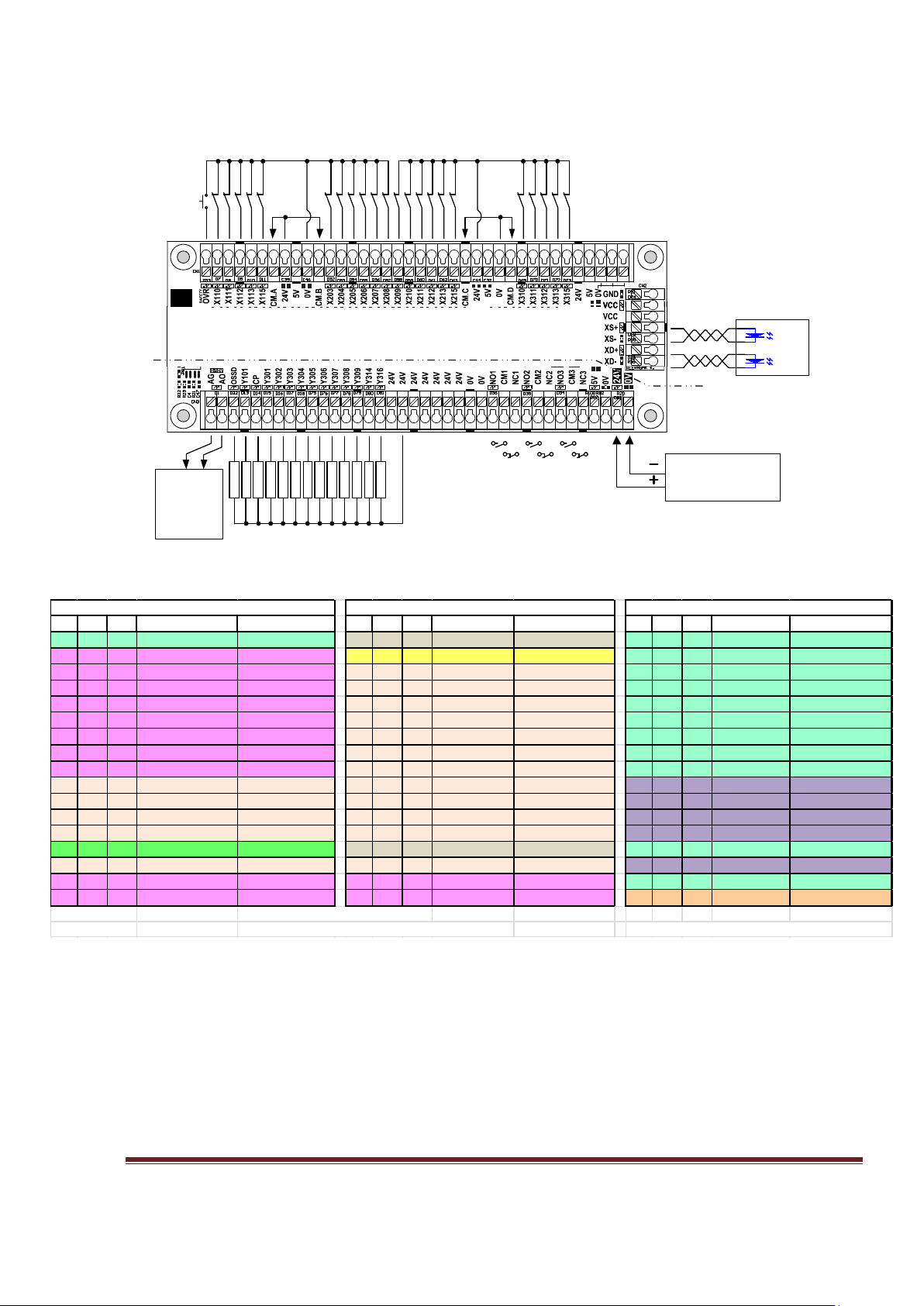
Pin I/O Act Term Name I/O Ty pe Pin I/O Act Term Name I/O Ty pe Pin I/O Act Ter m Name I/O Ty pe
1 O H SPD(Spindle) Sink output 1 O H NO1 Relay1 Contact 1 O H Y301 Sink output
2 O L XS (X Step) Line driver 2 I L OSSD
SafetyFeedBack 2 O H Y302 Sink output
3 O L XD (X Dir) Line driver 3 I L X203 NPN/PNP input 3 O H Y303 Sink output
4 O L YS (Y Step) Line driver 4 I L X204 NPN/PNP input 4 O H Y304 Sink output
5 O L YD (Y Dir) Line driver 5 I L X205 NPN/PNP input 5 O H Y305 Sink output
6 O L ZS (Z Step) Line driver 6 I L X206 NPN/PNP input 6 O H Y306 Sink output
7 O L ZD (Z Dir) Line driver 7 I L X207 NPN/PNP input 7 O H Y307 Sink output
8 O L AS (A Step) Line driver 8 I L X208 NPN/PNP input 8 O H Y308 Sink output
9 O L AD (A Dir) Line driver 9 I L X209 NPN/PNP input 9 O H Y309 Sink output
10 I L X110 NPN/PNP input 10 I L X210 NPN/PNP input 10 I L X310 NPN/PNP input
11 I L X111 NPN/PNP input 11 I L X211 NPN/PNP input 11 I L X311 NPN/PNP input
12 I L X112 NPN/PNP input 12 I L X212 NPN/PNP input 12 I L X312 NPN/PNP input
13 I L X113 NPN/PNP input 13 I L X213 NPN/PNP input 13 I L X313 NPN/PNP input
14 O H
CP(ChargePump)
Sink output 14 O H NO2 Relay2 Contact 14 O H Y314 Sink output
15 I L X115 NPN/PNP input 15 I L X215 NPN/PNP input 15 I L X315 NPN/PNP input
16 O L BS (B Step) Line driver 16 O L
CS (C Step)
Line driver 16 O H Y316 Sink output
17 O L BD (B Dir) Line driver 17 O L CD (C Dir) Line driver 17 O H AO Analog output
L=Low Active Analog PWM fre quency = 260 hz
H =High Active NO3 Relay3 ca n be c ontrolled by Y101, Y317, C P LPT 3 a ll inputs are high spee d inputs.
Port1 (output)
Port2 (Pins 2- 9 as input)
Port3 (Pins 2- 9 as o utput)
Figure 1, MB3 Overview Connection
Quick Reference is a summary for the experienced users.
Figure 1 is a shrinkage view of MB3 board. It shows the connection of inputs & outputs, power supply,
analog output for the VFD and axis signals.
Table 1 is a summary of Ports and Pins and their corresponding reference numbers. All pin numbers
preceded by an “X” are inputs and if preceded by a “Y” are outputs. Using X110 as an example. The
“X” means it is an input. The first digit “1” is the port number, the last 2 digits “10” is the pin number.
www.CNCRoom.com Page 6
Table 1, Ports and Pins Reference Tables
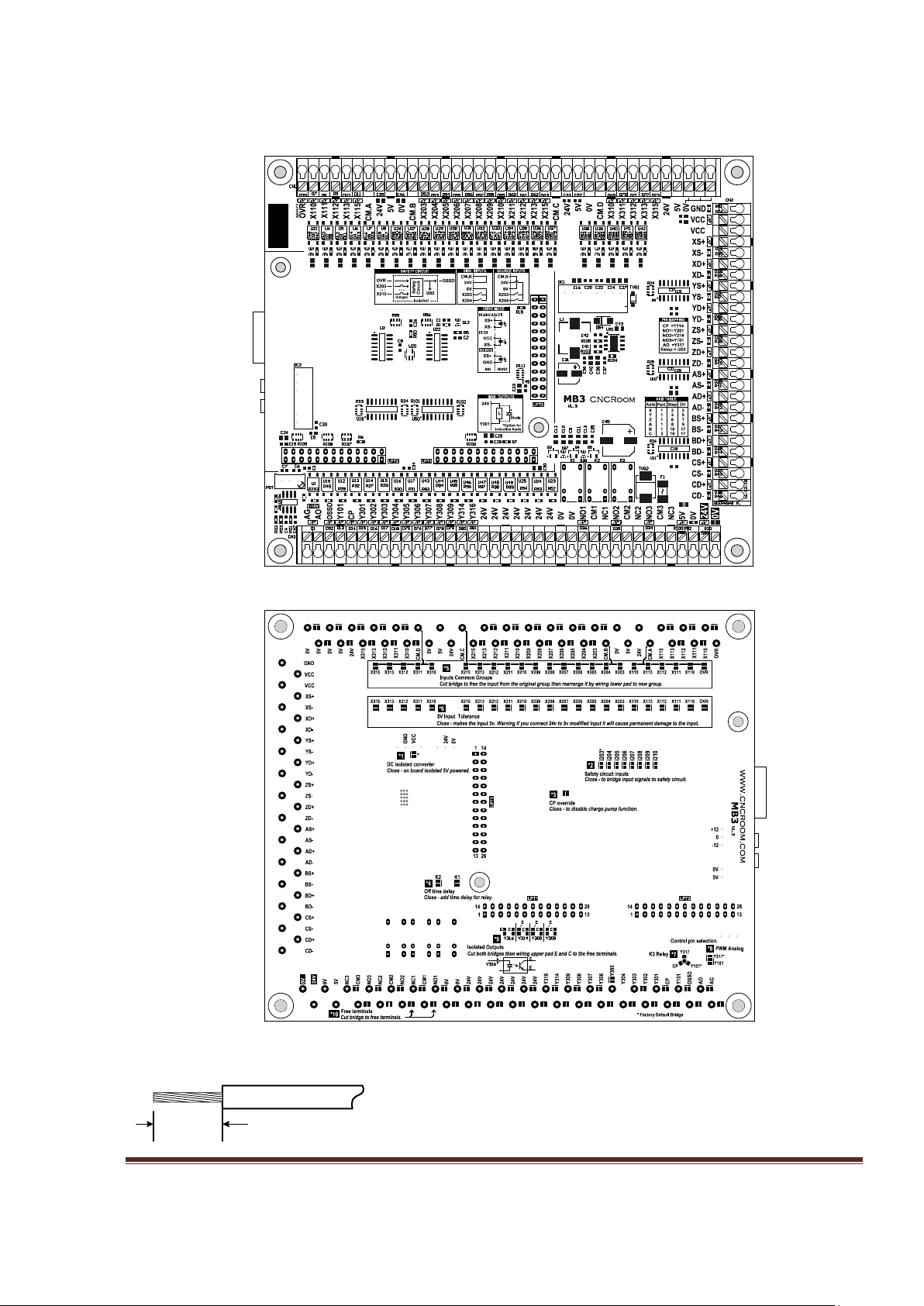
MB3 Layout
8–9mm
18-26 AWG
Figure 2, MB3 Board Layout
www.CNCRoom.com Page 7

Input (CN1) – Input terminals, consisting of 23 channels. NPN/PNP, 5/24V selectable.
Axis (CN2) – Axis signal terminals, consisting of 6 axes, which are; X, Y, Z, A, B, C
Output (CN3) – Output terminals, consisting of 14 NPN sink outputs, Analog signal, 3 Relay’s
NO/NC and an inlet for the 24Vdc power supply
LPT1-3 – Connectors for the ESS
RJ-45 – Communication connector, part of the ESS board
ESS and MB3 piggyback
The ESS receives its 5Vdc power from the MB3 when all three jumpers of ESS are closed, which
is the default setting. But you may need to change the jumpers do so before you install. This
eliminates the need for an external 5Vdc supply.
The Raspberry Pi tall headers are used for firm connection between ESS and MB3 board. This
allows ESS to be mounted on MB3 directly without any ribbon cables. This method will
eliminates a number of contact points, distance, inductance and resistance between ESS and
MB3 board which allows signals go forth and back faster. Furthermore, this makes both
companions look nicer, lower in height.
Figure 3, ESS board installation
www.CNCRoom.com Page 8
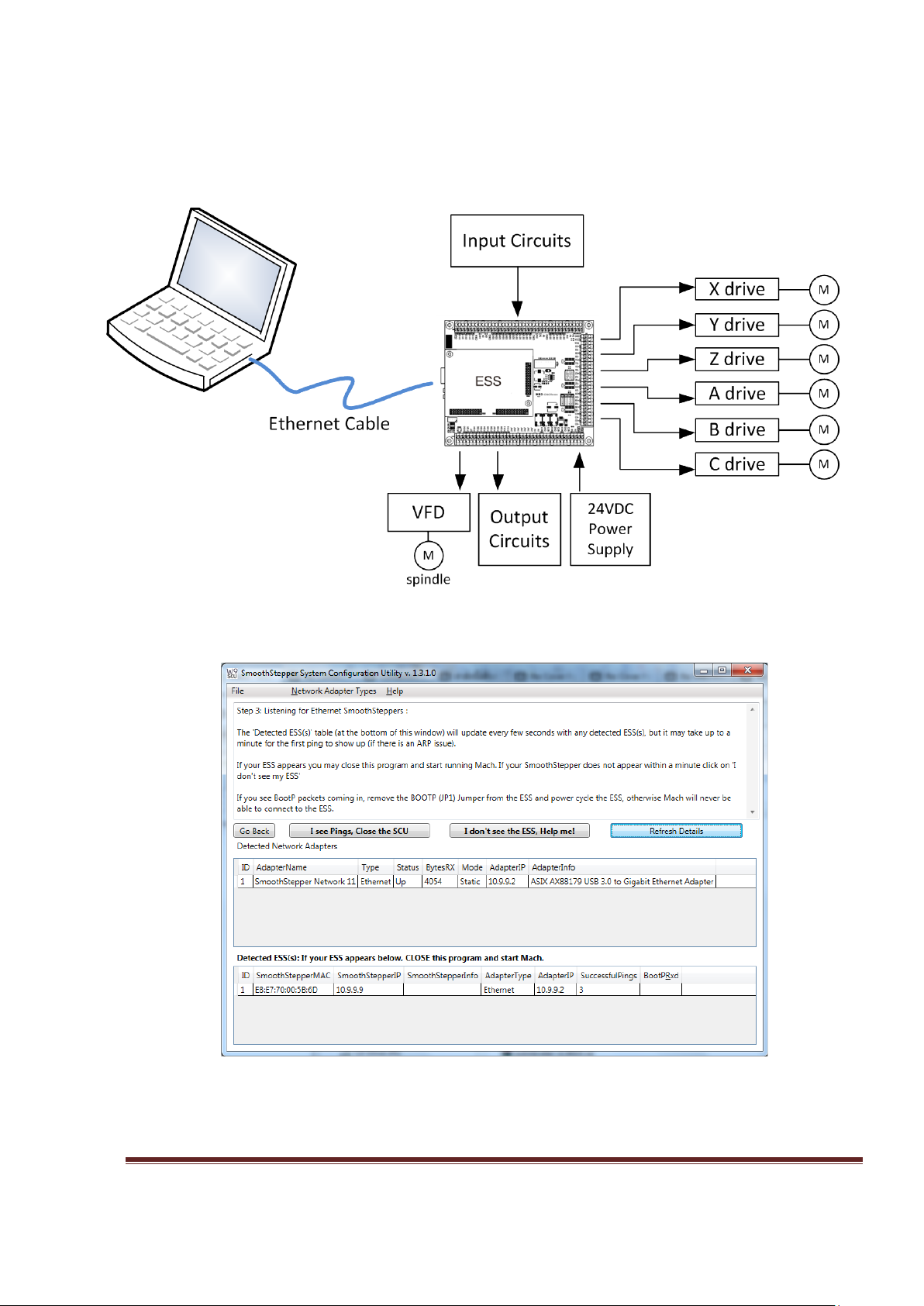
MB3 Connection Diagram
Figure 4, Connection Diagram
Figure 5, SCU utility successfully connected to the ESS.
The SCU software utility helps the user to configure Windows PC to communicate with ESS
easily. Below is the link to SCU tutorial video.
www.CNCRoom.com Page 9

https://www.youtube.com/watch?v=WonXbVGSVio
Hardware
Connecting the ESS to Your PC
Setting up networking for Ethernet device like ESS board is problematic for most beginners.
There are lot of tutorial video and guides from Warp9 Tech Design which help the user to
achieve this goal easily.
Warp9 Tech Design YouTube channel.
http://www.youtube.com/channel/UCpg3EROtW8xA_KzrFHgn4ZQ/videos
Figure 6, Youtube tutorial video for beginner.
Using the SCU to Fix Windows Firewall Issues
http://www.youtube.com/watch?v=RyRx7naF2rg
ESS Manual Setup
http://www.youtube.com/watch?v=3PahTqFQ05M
The following section has been copied with permission from the Warp9 website at;
http://www.warp9td.com/index.php/documentation/doc-ess#Connecting
The best way to connect your ESS to your PC is to use the Direct Connect method: hook the
Ethernet cable directly from your ESS to the network adapter in your PC. This will make trouble
shooting easier since there are no switches or routers between the ESS and your PC. (A switch
should be fine since it only operates in the lower 3 layers of the TCP/IP stack, but why add extra
equipment if you don't need it. A router should be fine if you only have your ESS and PC
www.CNCRoom.com Page 10

connected to it, but this will require more work to configure and setup. As a result we highly
recommend the direct connection, which is what the SCU [System Configuration Utility]
expects.)
If you don't have an Ethernet Adapter on your PC, we recommend using a PCI or PCI Express
Ethernet Adapter -OR- a USB 2.0 or USB 3.0 Ethernet Adapter. Quite a few people use these
alternatives successfully, including myself.
We STRONGLY discourage using a wireless connection to communicate with your ESS. There can
be much more latency or delay involved with wireless communications, along with a much
higher risk of dropped packets. The ESS needs a fast, stable, and consistent link to your PC.
Many people use a second Ethernet connection or their wireless connection on the PC so they
may easily connect to the internet, which is fine. When not running a machine.
While you are running Mach and your CNC system, we recommend that you refrain from
browsing the internet, gaming or streaming music or videos. This can cause your computer to
take too much time away from Mach which could cause lost communications with your ESS
(which can ruin your project).
We also recommend that you disable power saving options (monitor sleep and power off timers,
hard drive sleep timers, and computer sleep timers); these have been known to cause lost
communications with your ESS.
We also recommend that you set Windows Update to notify you that there are updates available
instead of automatically installing them on its own.
We also know of cases where antivirus and anti-malware software have caused problems. We
recommend that you disable them while you are running Mach, IF your PC is not connected to
the internet.
Note that you do not need to assign a static IP address to your computer if you program the ESS
to use an address that is in the same subnet as your computer. The subnet is the same if the first
3 groups of numbers in the IP addresses are the same. Quite often Internet routers will assign
addresses in the 192.168.0.x or 192.168.1.x ranges. If you wish to use a DHCP server for your
computer, you can do that but the ESS still needs to use a static IP address in the same subnet. A
direct connection to the ESS is the preferred way to go because there is no question as to
whether there is enough bandwidth available to run your machine reliably.
We STRONGLY RECOMMEND THAT YOU DO NOT hook your ESS up to the same Ethernet adapter
that you connect to the Internet with. There is no telling how much CPU and Ethernet bandwidth
is being used up by other applications or other devices on the network. It is therefore officially
discouraged. You are on your own if you wish to mix the Internet with your CNC data. However,
if you wish to change the IP address of the ESS, you may do so with the Configurator Utility.
www.CNCRoom.com Page 11
If the remainder of this section confuses you, don't worry. The SCU in the next section will do all
0V
24V
of the work for you in just a few mouse clicks! The remainder of this section is just to document
what the ESS uses and needs, you may skip to the SCU section.
The ESS comes configured from the factory with a default static IP address of 10.9.9.9 With your
ESS at 10.9.9.9, you will need to assign your network adapter to use 10.9.9.2 or another valid
and unused address in the subnet. We recommend that you keep the 10.9.9.9 IP address
assigned to your ESS, since all of our documentation and videos will use that value. In fact MOST
the user keeps this value assigned to their ESS. However, if there is a need to change it, you may
do so with the Configurator Utility.
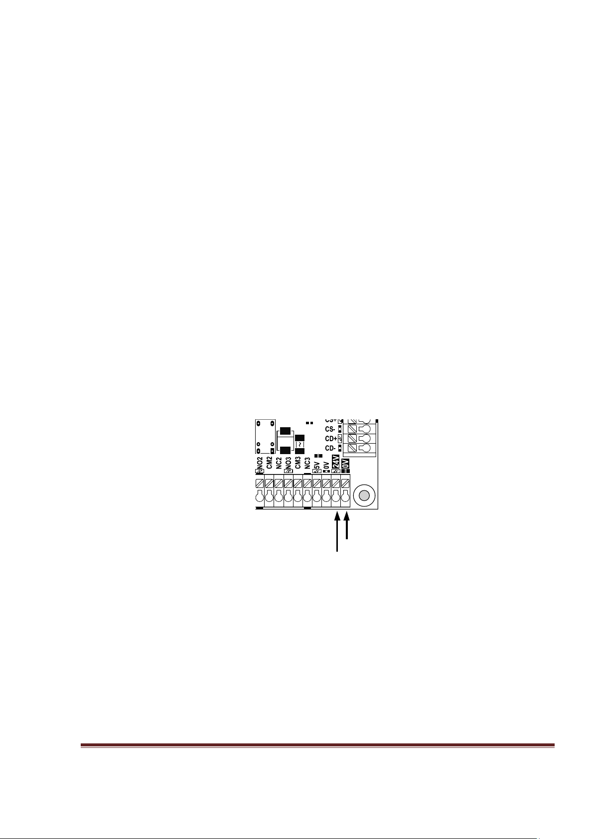
Power Supply
The MB3 needs only a single 24Vdc power supply to operate the board. Figure 7, shows power
supply input terminals for 0V and 24V. The 24V, 3A power supply is recommended for general
usage.
There is a non-isolated step-down switching regulator that converts 24V (18-24Vdc) down to 5V
to power most parts of the circuit, including the inputs and outputs.
However, there are also two special isolated DC2DC convertors are used to power the ESS board
and AnaSpeed2, 0-10V analog output.
On board there is also a small fuse for protection against over voltage and polarity reversal.
Figure 7, Power supply connection
www.CNCRoom.com Page 12
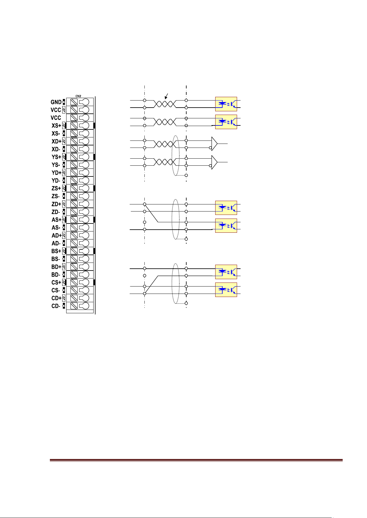
Axis Connection X, Y, Z, A, B, C
VCC
Dir+
Step+
Dir-
Step-
optocoupler
XD-
XS-
(a) differential connection
XD+
XS+
Dir+
Step+
Dir-
Step-
XD-
XS-
Line Reciever
XD+
XS+
Dir+
Step+
Dir-
Step-
Optocoupler
XD-
XS-
twisted pair
cable
(b) single end sink connection
GND
Dir+
Step+
Dir-
Step-
optocoupler
XD+
XS+
(c) single end source connection
MB3
*grounding at drive side
*grounding at drive side
*grounding at drive side
Drive input
AXIS CN2 terminal supplies motion command for drives.
There are three different methods of connecting your drives to CN2.
Figure 8 (a) Differential connection has the best noise immunity. It is recommended to use
differential mode if possible.
Figure 8 (b) Single end sink connection is used if the exist connection system follows this fashion.
Figure 8 (c) Single end source connection is used if the exist connection system follows this
fashion. This connection is similar to computer parallel port.
www.CNCRoom.com Page 13
Figure 8, Axis command terminal and various connection modes

Inputs
By default, all MB3 inputs are 24V tolerance for industrial sensors and switches.
However, sometimes we need to interface with 5V devices, such as MPG and low
voltage sensors. On page 25, topic [*6]. 5V input tolerance shows the way to makes
the MB3 board accepts low voltage. It is recommended to use shielded cable with
shield grounded to one side only star configuration. Placing terminals or ground lugs
close to the MB3 makes for neater wiring to land shields and 0 or 5/24Vdc. The neater
your wiring the easier to work with or add to. You should also consider the whole
wiring scheme before wiring as you do not want to continually cross wires as this
makes for a rats nest.
Figure 9, Input terminals
Figure 9 shows 23 input terminals. There are all universal inputs, divided into 4 main
groups. Each group has its own common terminal.
CM.A (OVR, X110, X111, X112, X113, X115)
CM.B (X203, X204, X205, X206, X207, X208)
CM.C (X209, X210, X211, X212, X213, X215)
CM.D (X310, X311, X312, X313, X315)
The common pin is used to select NPN or PNP. For example if CM.A connects to 24V, all
inputs in this group become NPN type and it waits for 0V to be presented at the X1xx
terminal to make input active, the status LED will lights up.
On the other hand, if CM.A connects to 0V, all inputs in this group become PNP and it
waits for 24V to be present at X1xx the terminal to make input active, the status LED
will light up.
By default all inputs accept 24V, However if 5V input is preferred for particular inputs
the user can bridge the solder-bridge underneath of MB3 board.
www.CNCRoom.com Page 14
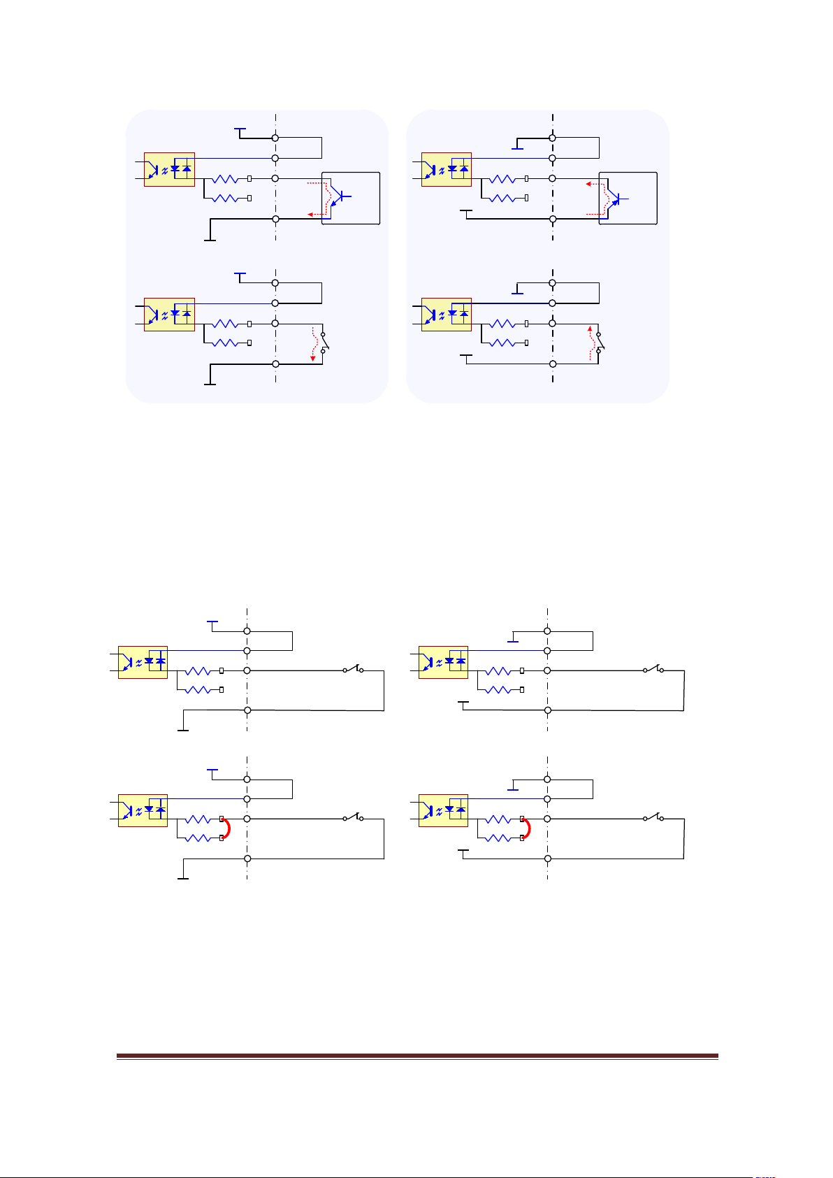
Input Type
0V
24
V
connect to 0V
MB
3
X203
CM.B
5
V SB Open
0V
24V
0V
24
V
MB3
X203
CM.B
5
V SB Open
0V
24V
NPN Transistor
of external device
Switch
24v
0
V
connect to
24V
MB3
X
203
CM.
B
5V SB Open
24
v
0
V
24v
0
V
MB3
X203
CM
.B
5V SB Open
24
v
0
V
Switch
PNP Transistor
of external device
NPN Type
PNP Type
0V
24V
24V NPN inputs
MB3
X203
CM.A
5V SB Open
0V
24V
24v
0V
24V PNP inputs
MB3
X203
CM.A
5V SB Open
24v
0V
0V
5V
5V NPN inputs
MB3
X203
CM.A
5V SB Close
0V
5V
5v
0V
5V PNP inputs
MB3
X203
CM.A
5V SB Close
5v
0V
Figure 10, Input Type: NPN/PNP, SINK/SOURCE
The words ‘NPN’ and ‘PNP’ of input type come from output transistor of connected
device which conducts current from one side to another side. The NPN transistor will
sink current from collector to emitter. The PNP transistor will source current from
emitter to collector. Sometimes, we hear the words ‘sink’ and ‘source’ with NPN and
PNP respectively.
Basic input connection with switches
Figure 11, shows the 4 different methods to connect a switch with on board power
supply. On the left side is NPN input type which connects a switch between input X203
and 0V. On the right side is PNP input type which connects a switch between input
X203 and power source 24V or 5V.
www.CNCRoom.com Page 15
Figure 11, Basic input connections with internal power
24
V
24
V NPN inputs
MB
3
X
203
CM
.
B
5V SB Open
0
V 24
V
24
V PNP inputs
MB3
X203
CM
.
B
5
V SB Open
0
V
5V
5
V NPN inputs
MB
3
X203
CM
.
B
5V SB Close
0V
5
V
5V PNP inputs
MB
3
X203
CM.B
5
V SB Close
0V
0V
X203
CM.B
5V SB Open
0V
PNP inputs
MB3
X204
5V SB Close
5v
24v
5V SB Close
X205
5v
24v
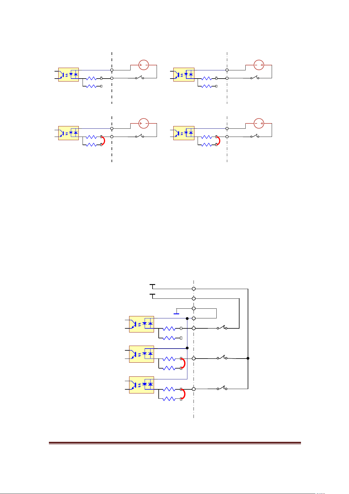
Figure 12, Basic input connections with external power
Figure 12 shows the 4 different methods to connect a switch with external power
supply. These connections are totally isolated from any part of the MB3 circuit. The
external circuits, for instance, could be the fault output of a VFD drive or plasma cutting
system, where rough interference noise appears on the device. Totally isolation is a key
to help ESS/MB3 avoiding from extreme interference.
www.CNCRoom.com Page 16
Figure 13, Common 0V or PNP inputting can mix and match between 24V and
5V inputs
0V
X203
CM.B
5V SB Open
NPN inputs
MB3
X204
5V SB Open
24v
5V SB Open
X205
24v
0V
Y Z X
X+ X- Y+ Y- Z+ Z-
E-Stop
Limit
Home
Figure 14, Conventional series connection of LIMIT and HOME switches.
0V
24V
24V NPN output sensor
MB3
X110
CM.A
5V SB Open
black,white
blue
brown
24V
0V
MB3
X110
CM.A
5V SB Open
black,white
blue
brown
0V
5V
5V NPN output sensor
MB3
X110
CM.A
5V SB Close
black,white
blue
brown
24V PNP output sensor
OMRON EE-SX
24v
0V
24v
5v
0V
0V
Figure 14 shows the NC contacts are wired in series to form AND logic. This is a
conventional method to preserve some inputs for other tasks.
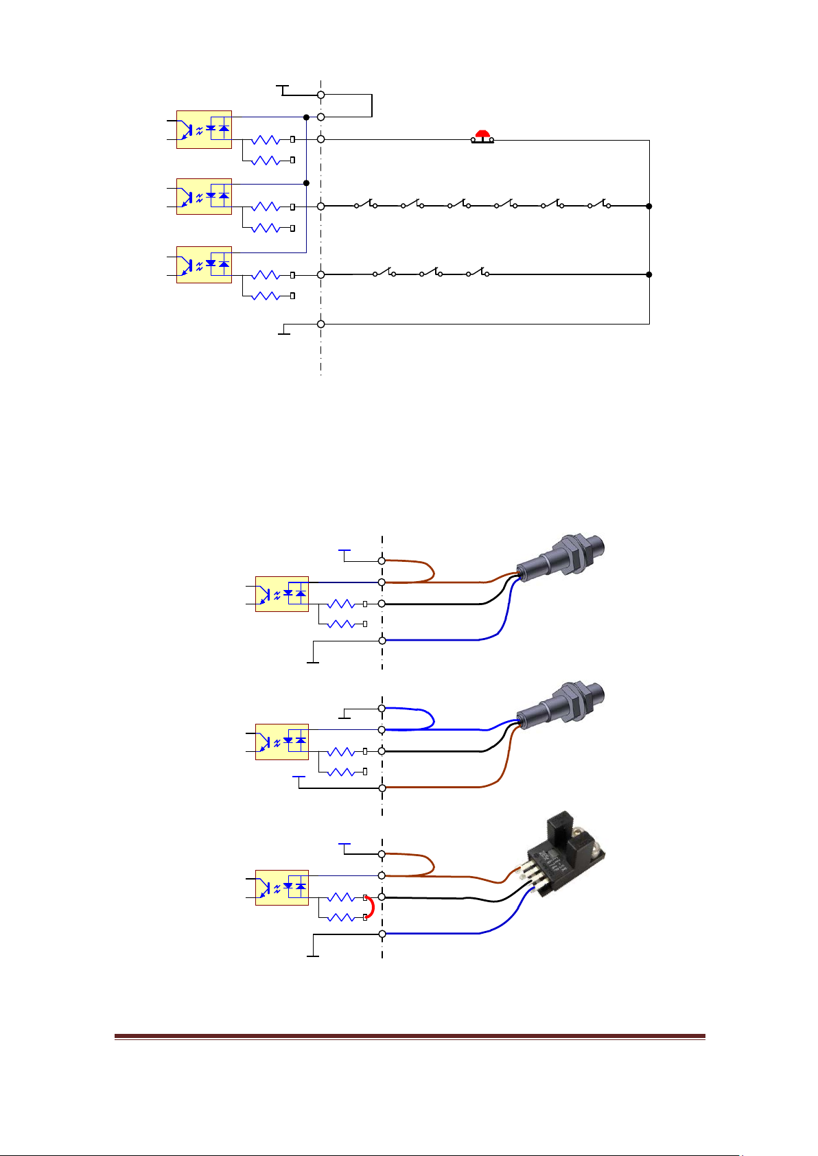
Sensors
Figure 15, Sensor connections
Figure 15 shows the way to make connection with standard industrial sensors.
www.CNCRoom.com Page 17
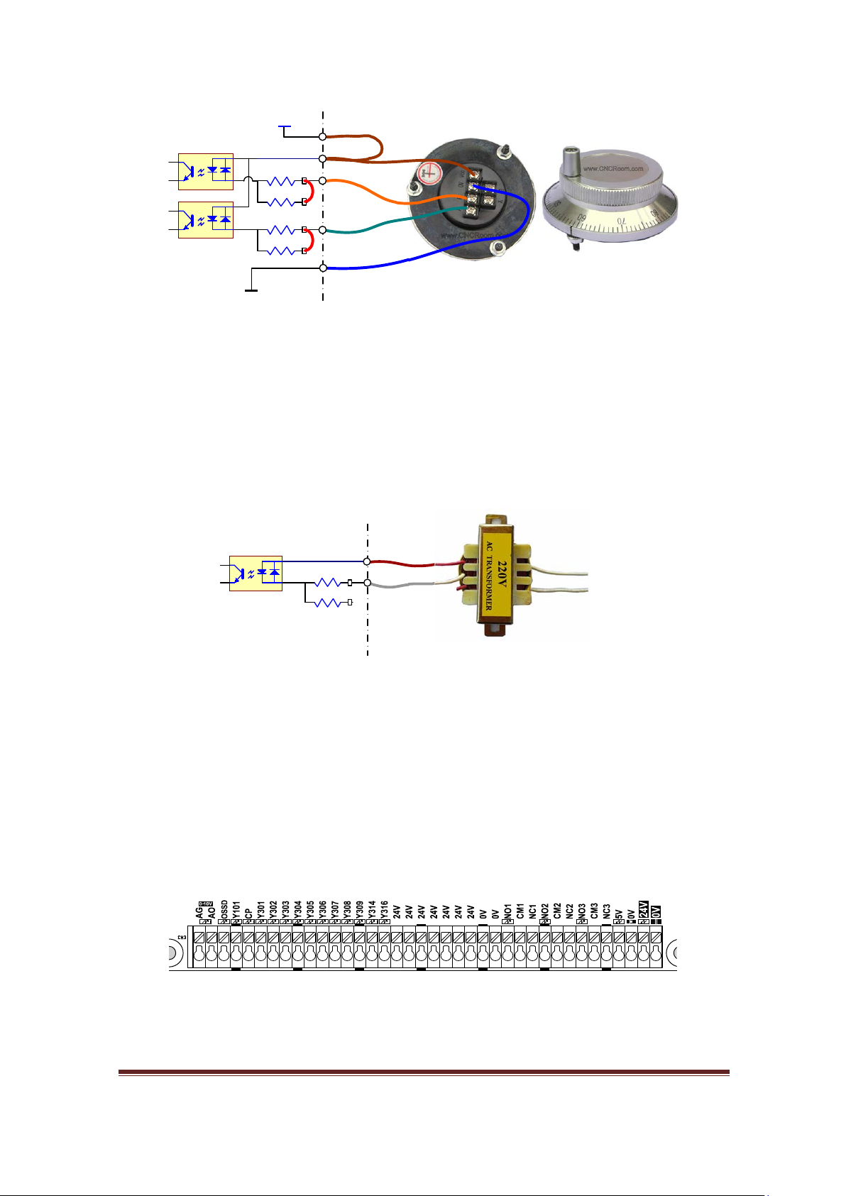
MPG / Encoder
5V
X310
CM.D
5V SB Close
5V NPN MPG/Encoder
MB3
5V SB Close
X311
0V
MB3
5V SB Open
X
311
CM
.D
AC inputs for black out sensing
110
/220VAC
24 VAC
Figure 16, MPG/Encoder connection circuit
MB3 board allows us to make a connection to low voltage devices. In this case, Figure
16 a 5V MPG device. It is similar to most encoders. Some encoders can do both source
and sink. So, it depends on us what input type we want to connect. The Figure 10, on
page 15 gives you an idea how to approach it.
AC input
Figure 17, AC source interfacing.
Sometime we would like to make a connection with strange part. Figure 17 shows how
to connect and sense an AC signal. If a brown out or black out happened the controller
is able to know beforehand then it commands lock z axis brake before all devices losing
power. In this case, some power must be kept in a big capacitor as a backup for
controller and drives for few seconds only.
Outputs
Transistor Sink Output
Figure 18 shows 14 output terminals, each output can sink current up to a maximum of
Figure 18, Output terminals
70mA with a total maximum of 500 mA per group of 7 outputs.
www.CNCRoom.com Page 18
 Loading...