

CNCroom MB2 Owner's Manual

MachBob2 (MB2)
Owner’s manual
Doc E1.6Rev5 (8/17/2017)
for PCB ver 1.3, 1.5 and 2.0
www.CNCRoom.com Page 1

Introduction
It is perhaps well understood that in an industrial environment, personal computers, motion
control boards and logic signals can face a large amount of interference from things such as
power cables, motors, welding machines, magnetic contactors etc.
We can help to minimize the effects of this interference by having any susceptible electronics
enclosed in a metal control cabinet and using the correct safety and best practice techniques,
which include, but are not limited to the installation of noise reduction such as an isolated
transformer and noise filters.
While these things will help us achieve a better result, using a control board designed for
industrial applications can be more important.
MachBob2 (MB2) is designed for industrial application and specifically to work with the Ethernet
Smooth Stepper (ESS) which is an excellent motion control board designed to be used with
Mach3 and Mach4
Specification and Features
• By using an Ethernet connection, the ESS is far more noise resistant than when using a USB or
parallel Port connection and therefore helps to protect the logic signal when the controller
and drives are located a large distance from the computer.
• Runs on Mach3 / Mach4 with Windows XP, Win7, Win8 both 32 and 64 bit, on both desktop
and notebook computers.
• New! Utilizes All 3 ports of the ESS.
• New! The Motion Command Signal can be selected between Pulse/Sign, CW/CCW, and
Quadrature. Frequency can be selected from 32 kHz to 4 MHz
• New! Differential line driver for motion signals, allows for longer wiring with more resistance
to interference when compared to TTL open end.
• New! A single 24Vdc Power Supply is needed. There is a 5Vdc isolated and non-isolated dc2dc
converter on board, thus saving installation space and wiring.
• New! OSSD (Output Signal Switching Device) outputs and safety circuit are implemented when
a peripheral device such as a servo motor drive or a spindle VFD (Variable Frequency Drive)
trigger an alarm condition, which causes the Safety Circuit to disengage the OSSD output. This
method is used on large CNC machines to cut power from the drives.
• New! LED status for all inputs and outputs including motion control signals. Makes it much
easier to diagnose and trouble shoot.
• Isolated power and ground between the PC, ESS and I/O, which eliminates crossover noise and
ground loop problems.
• New! Polarity and over voltage protection (in conjunction with a fuse) for the 24Vdc power
supply.
www.CNCRoom.com Page 2

• An “AnaSpeed” circuit has been implemented. This circuit is totally isolated from the MB2 and
forms a part of the VFD inverter, acting as a digital VR (variable resistor). High voltage noise
from the inverter cannot cause interfere through this connection.
• A charge-pump signal is provided. This helps the user to form a safety interlock condition
between controller and devices.
• 22 isolated input terminals, consisting of 17 terminals of NPN and 5 terminals of PNP type.
• 14 NPN isolated output terminals capable of sinking current up to 100mA for each channel and
up to 500mA per group.
• New! MB2v1.5 and 2.0 - 2 onboard relays with both NO/NC contacts and “Off Delay Time”,
which can be used for such application as “Z Drop Protection.” (MB2v1.3 does not have this
feature)
• New! MB2v2.0 -The K2 Relay can now be controlled by a charge pump signal. Please notice
blue arrow on page19, Figure 19, the underneath layout of the MB2. Showing the appropriate
solder bridge for modification.
• Spring terminals for quicker connecting and disconnecting of cables. They are resistant to
vibration, so no more screws which have rattled loose and no more forgetting to tighten.
Precaution
• Remember to static discharge before touching any part of ESS/MB2. Ground your body
by wearing a grounding strap or frequent touching an earthed metal chassis to release
electrostatics.
• Make sure that there is no high voltage leak from your soldering iron when soldering
the solder-bridge – the safest way is to unplug your soldering iron from the mains
power when it has reached a high enough temperature to melt the solder. High voltage
leakage from a cheap soldering iron can potentially damage the integrated circuit (IC)
on the MB2 board.
• The MB2 board is Fragile, do not drop, as it could badly damage the electronics.
• In certain circumstances, it could be possible for the MB2 board to build up excessive
heat if many of the inputs and outputs are active at same time over an extended
period. It is therefore advisable to install a good quality cooling fan to ventilate the
cabinet.
www.CNCRoom.com Page 3
Quick Reference
L
L
L
L
L
L
L
L
L
L
L
L
L
L
24Vdc
Power Supply
24Vdc
VFD Inverter
Analog vi
Foward
(b)Single end
connection
(a)Differential
connection
Drive
Drive
Ports and Pins meaning
X110 = input, port 1, pin 10
Y301 = output, port 3, pin 01
Abbr.
Meaning Output
SPD
Sp indle
Y101
CP ChargePump Y114
NO1 Normal Open Contact1 Y201
NO2 Normal Open Contact2 Y214
AO Analog Output Y317
Abbreviation and Ports/Pins
Pin I/ O Te r m Name
I/ O Ty p e Pin I/ O Te r m Name I/O Type Pin I/ O Te r m Name I/ O Ty pe
1 O SPD(Spindle) Sink output 1 O NO1 Relay1 Contact 1 O Y301 Sink output
2 O XS (X Step) Line driver 2 I OSSD Sink Output 2 O Y302 Sink output
3 O XD (X Dir) Line driver 3 I X203 NPN input 3 O Y303 Sink output
4 O YS (Y Step) Line driver 4 I X204 NPN input 4 O Y304 Sink output
5 O YD (Y Dir) Line driver 5 I X205 NPN input 5 O Y305 Sink output
6 O ZS (Z Step) Line driver 6 I X206 NPN input 6 O Y306 Sink output
7 O ZD (Z Dir) Line driver 7 I X207 NPN input 7 O Y307 Sink output
8 O AS (A Step) Line driver 8 I X208 NPN input 8 O Y308 Sink output
9 O AD (A Dir) Line driver 9 I X209 NPN input 9 O Y309 Sink output
10 I X110 NPN input 10 I X210 NPN input 10 I X310 PNP input
11 I X111 NPN input 11 I X211 NPN input 11 I X311 PNP input
12 I X112 NPN input 12 I X212 NPN input 12 I X312 PNP input
13 I X113 NPN input 13 I X213 NPN input 13 I X313 PNP input
14 O CP(ChargePump) Sink output 14 O NO2 Relay2 Contact 14 O Y314 Sink output
15 I X115 NPN input 15 I X215 NPN input 15 I X315 PNP input
16 O BS (B Step) Line driver 16 O
CS (C Step)
Line driver 16 O Y316 Sink output
17 O BD (B Dir) Line driver 17 O CD (C Dir) Line driver 17 O AO Analog output
Port1 (output)
Port 2 (Pins 2-9 a s input)
Port 3 (Pins 2-9 a s out put)
Shrinkage part
*Output can sink current up to 100mA
and up to 500mA per group of 7 pins
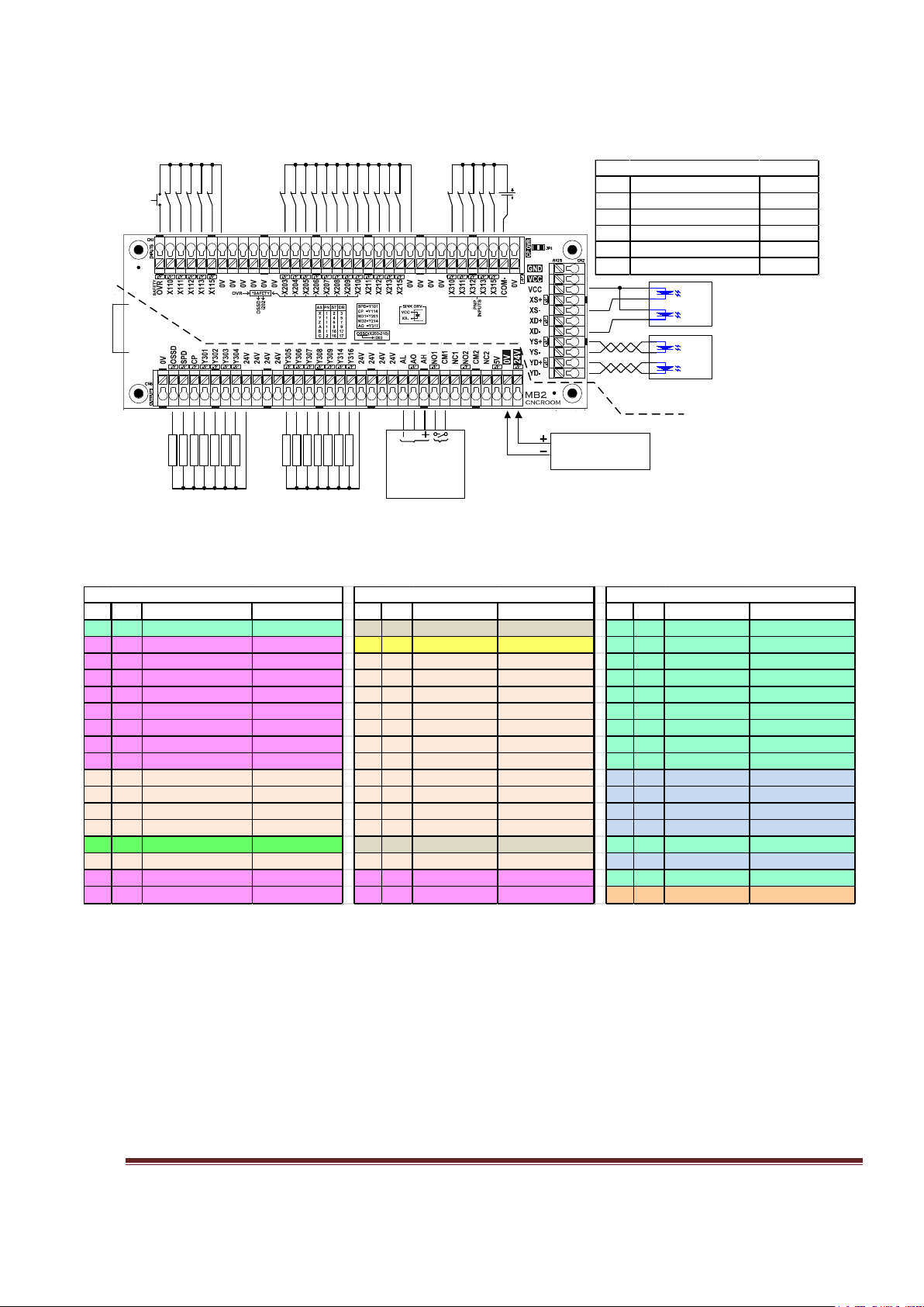
Figure 1, MB2 Overview Connection
Table 1, Ports and Pins Reference Tables
Quick Reference is a summary for the experienced user.
Figure 1 is a shrinkage view of MB2 board. It shows the connection of inputs & outputs, power supply,
analog output for the VFD and axis signals, including differential and single end connections. If
possible, it is suggested that you should first try the differential connection option as shown in Figure 1
(a), as it is more noise resistant than the single end connection of Figure 1 (b)
Table 1 is a summary of Ports and Pins and their corresponding reference numbers. All pin numbers
preceded by an “X” are inputs and if preceded by a “Y” are outputs. Using X110 as an example. The
“X” means it is an input. The first digit “1” is the port number, the last 2 digits “10” is the pin number.
www.CNCRoom.com Page 4
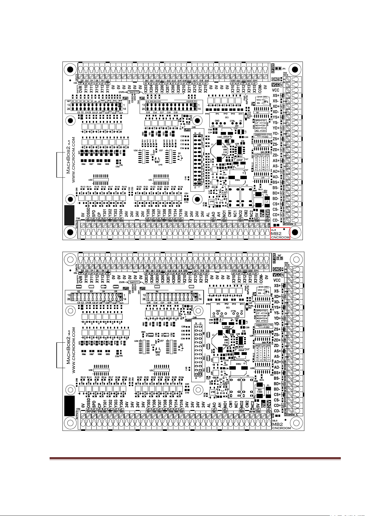
MB2 Layout
MB2v1.5
MB2v2.0
Figure 2, MB2 version 1.5 VS version 2.0 Board Layout
www.CNCRoom.com Page 5
8–9mm
18-26 AWG
Input (CN1) – Input terminals, consisting of 18 channels of NPN type and 5 channels of PNP
type
Axis (CN2) – Axis signal terminals, consisting of 6 axes, which are; X, Y, Z, A, B, C
Output (CN6) – Output terminals, consisting of 14 NPN sink outputs, Analog signal, 2 Relay’s
NO/NC and an inlet for the 24Vdc power supply
LPT1-3 (CN3-5) – Connectors for the ESS
JP1 – Charge Pump override
RJ-45 – Communication connector, part of the ESS board
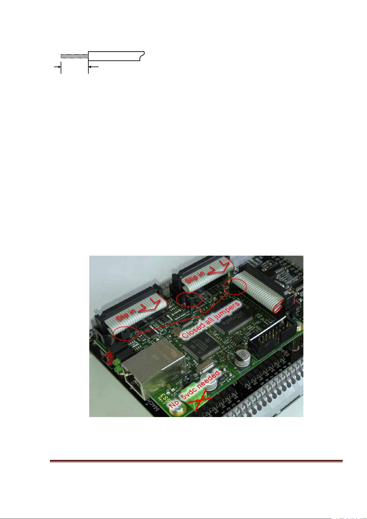
ESS and MB2 piggyback
The ESS receives its 5Vdc power from the MB2 when all three jumpers are closed, which is the
default setting. This eliminates the need for an external 5Vdc supply, See Figure 3 below. Any
excess in the ribbon cables, has been adjusted to inboard side of the cable clamp, see Figure 4,
this enables you to clearly see the LED status and terminal labels.
Figure 3, Jumpers are closed, No external 5Vdc
www.CNCRoom.com Page 6
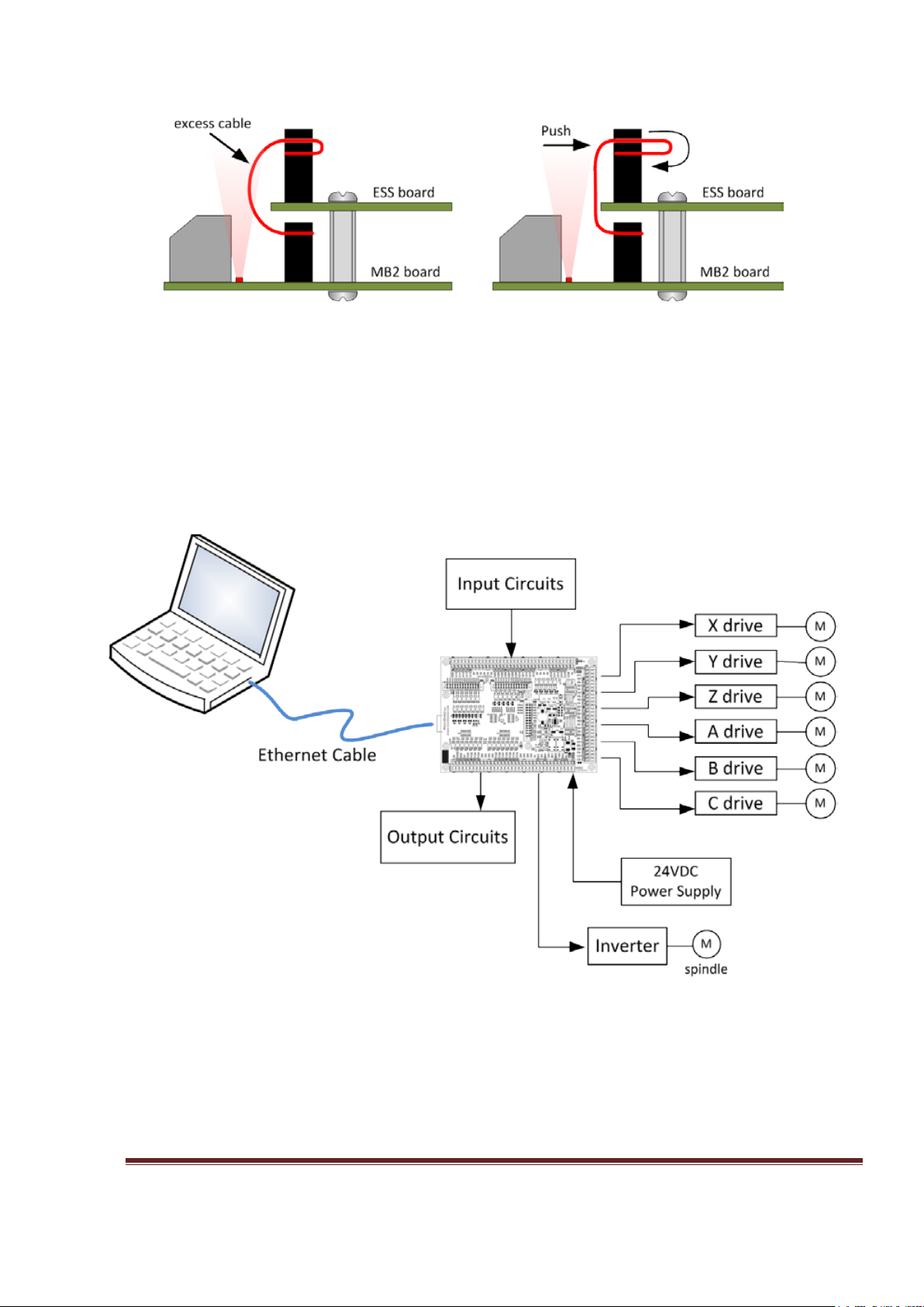
Figure 4, Excess cable has been adjusted to give clear sight of the LEDs and terminal labels
MB2 Connection Diagram
Figure 5, Connection Diagram
www.CNCRoom.com Page 7

Hardware
Connecting the SmoothStepper to Your PC
The following section has been copied with permission from the Warp9 website at;
http://www.warp9td.com/index.php/documentation/doc-ess#Connecting
The best way to connect your ESS to your PC is to use the Direct Connect method: hook the
Ethernet cable directly from your ESS to the network adapter in your PC. This will make trouble
shooting easier since there are no switches or routers between the ESS and your PC. (A switch
should be fine since it only operates in the lower 3 layers of the TCP/IP stack, but why add extra
equipment if you don't need it. A router should be fine if you only have your ESS and PC
connected to it, but this will require more work to configure and setup. As a result we highly
recommend the direct connection, which is what the SCU [System Configuration Utility]
expects.)
If you don't have an Ethernet Adapter on your PC, we recommend using a PCI or PCI Express
Ethernet Adapter -OR- a USB 2.0 or USB 3.0 Ethernet Adapter. Quite a few people use these
alternatives successfully, including myself.
We STRONGLY discourage using a wireless connection to communicate with your ESS. There can
be much more latency or delay involved with wireless communications, along with a much
higher risk of dropped packets. The ESS needs a fast, stable, and consistent link to your PC.
Many people use a second Ethernet connection or their wireless connection on the PC so they
may easily connect to the internet, which is fine.
While you are running Mach and your CNC system, we recommend that you refrain from
browsing the internet, gaming or streaming music or videos. This can cause your computer to
take too much time away from Mach which could cause lost communications with your ESS
(which can ruin your project).
We also recommend that you disable power saving options (monitor sleep and power off timers,
hard drive sleep timers, and computer sleep timers); these have been known to cause lost
communications with your ESS.
We also recommend that you set Windows Update to notify you that there are updates available
instead of automatically installing them on its own.
We also know of cases where antivirus and anti-malware software have caused problems. We
recommend that you disable them while you are running Mach, IF your PC is not connected to
the internet.
Note that you do not need to assign a static IP address to your computer if you program the ESS
to use an address that is in the same subnet as your computer. The subnet is the same if the first
3 groups of numbers in the IP addresses are the same. Quite often Internet routers will assign
www.CNCRoom.com Page 8

addresses in the 192.168.0.x or 192.168.1.x ranges. If you wish to use a DHCP server for your
computer, you can do that but the ESS still needs to use a static IP address in the same subnet. A
direct connection to the ESS is the preferred way to go because there is no question as to
whether there is enough bandwidth available to run your machine reliably.
We STRONGLY RECOMMEND THAT YOU DO NOT hook your ESS up to the same Ethernet adapter
that you connect to the Internet with. There is no telling how much CPU and Ethernet bandwidth
is being used up by other applications or other devices on the network. It is therefore officially
discouraged. You are on your own if you wish to mix the Internet with your CNC data. However,
if you wish to change the IP address of the ESS, you may do so with the Configurator Utility.
If the remainder of this section confuses you, don't worry. The SCU in the next section will do all
of the work for you in just a few mouse clicks! The remainder of this section is just to document
what the ESS uses and needs, you may skip to the SCU section.
The ESS comes configured from the factory with a default static IP address of 10.9.9.9 With your
ESS at 10.9.9.9, you will need to assign your network adapter to use 10.9.9.2 or another valid
and unused address in the subnet. We recommend that you keep the 10.9.9.9 IP address
assigned to your ESS, since all of our documentation and videos will use that value. In fact MOST
the user keep this value assigned to their ESS. However, if there is a need to change it, you may
do so with the Configurator Utility.
www.CNCRoom.com Page 9

Axis Connection X, Y, Z, A, B, C
VCC
Dir+
Step+
Dir-
Step
-
optocoupler
XD-
XS-
(a) differential connection
(b)
single end connection
XD+
XS+
Dir+
Step+
Dir-
Step-
*grounding at drive side
XD-
XS-
Line Reciever
XD
+
XS
+
Dir+
Step
+
Dir-
Step
-
Optocoupler
XD
-
XS-
*grounding at drive side
Cable Drive Input
Twisted pair
AXIS CN2 terminal supplies motion command for drives.
MB2
There are two modes to make connection to CN2.
Figure 6 (a) Differential mode has the best noise immunity. It is recommended to use differential
mode if possible.
Figure 6 (b) Single end mode is used if the drive is not compatible with differential mode. There
are two points of VCC to share with all axes.
www.CNCRoom.com Page 10
Figure 6, Axis command terminal and various connection modes
Inputs
0V
X211
24V
By default, all MB2 inputs are 24V tolerance for industrial sensors and switches. However, sometimes
we need to interface with 5V devices, such as MPG and low voltage sensors. On the topic “
for low voltage devices” shows the way to hack the MB2 board and a simple interface circuit.
Switches
5V inputs
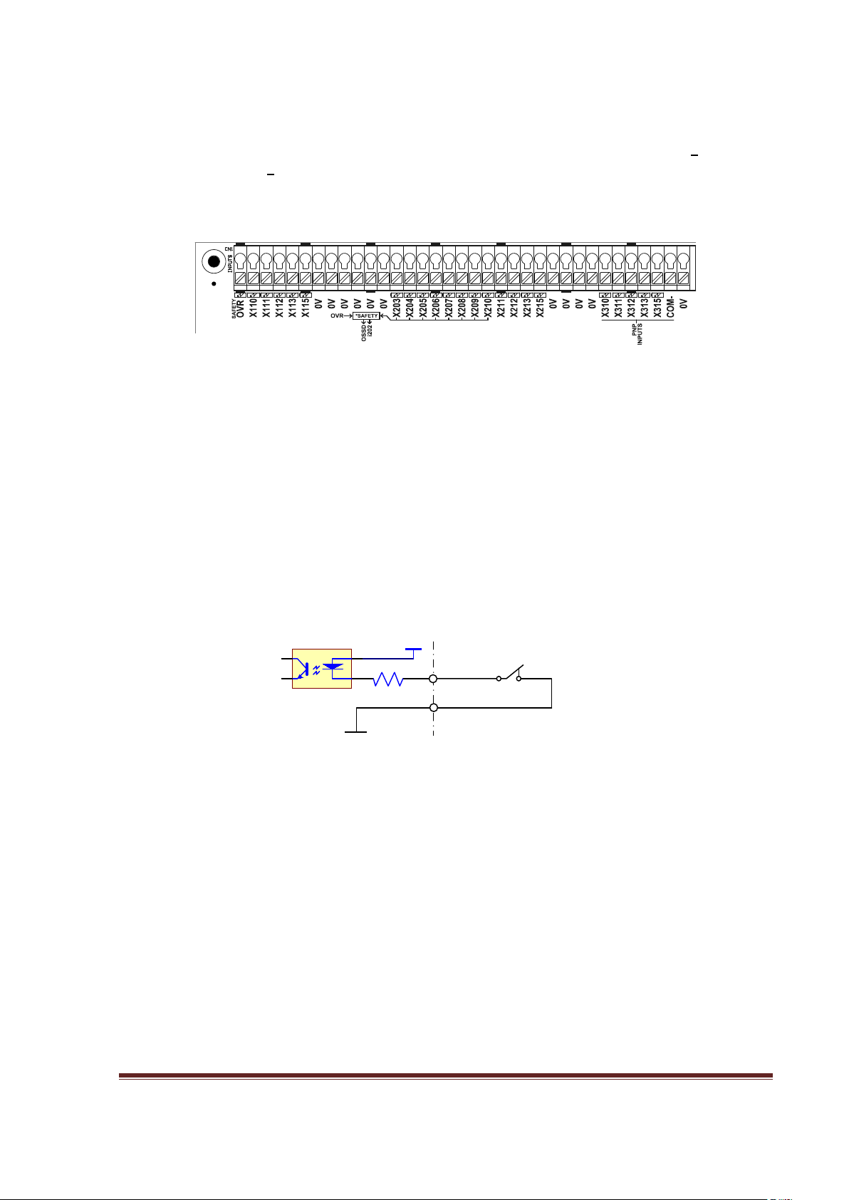
Figure 7, Input terminals
Figure 7 shows 22 input terminals. There are 17 points of NPN type which are X110-X115,
X203-X215 and 5 points of PNP type which are X310-X315.
There are solder-bridges underneath of MB2 board for the user to bridge the input status of
inputs X203 – X210 to safety circuit (see page 18). Use the “OVR” input as the override signal
for the OSSD safety circuit.
The Safety Circuit forms an “AND” logic for all involved signals. This eliminates the need to
build a separate safety circuit, hopefully saving the user time and money.
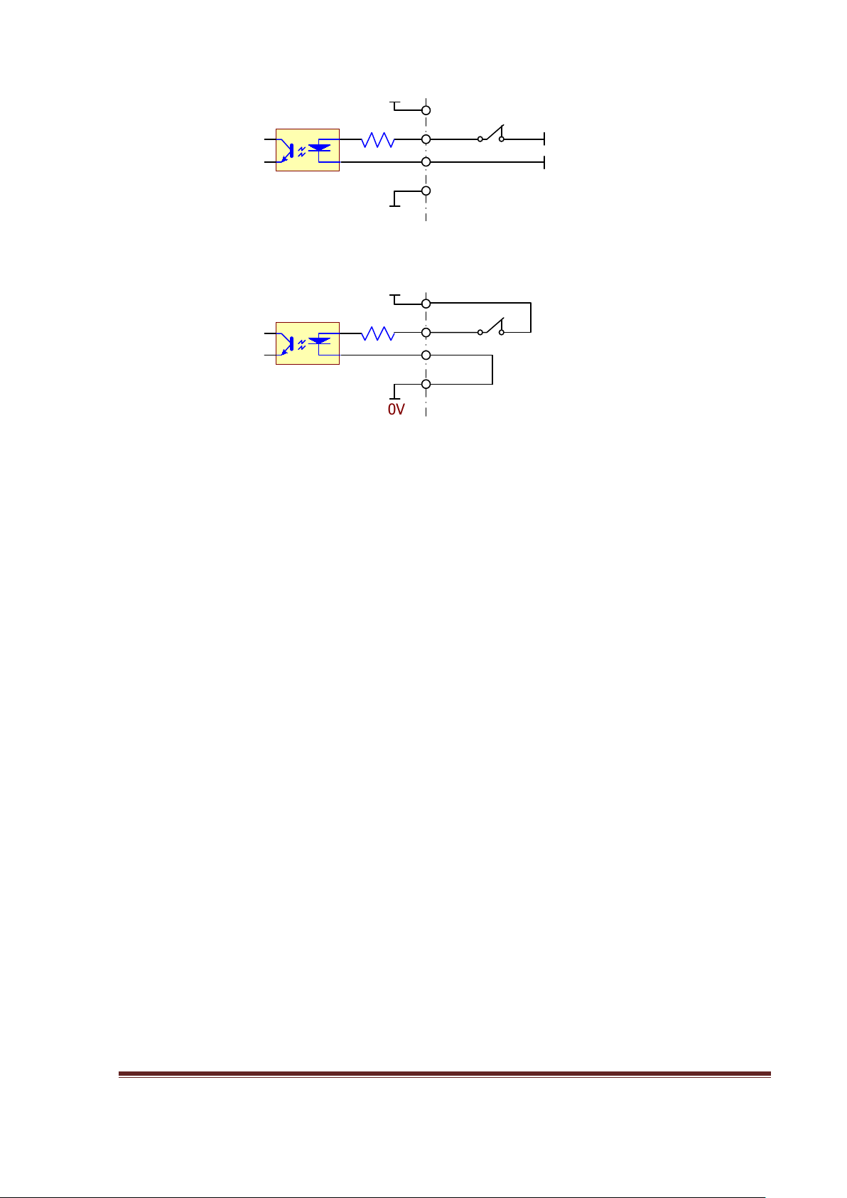
Figure 8, Connection of the NPN inputs, it references to 0V
MB2 NPN inputs connect to 0V
Figure 8
www.CNCRoom.com Page 11
, shows the conventional way to connect a switch to an NPN input, X211 with 0V
X
310
24V
0V
X310
24V
0V
0V
24V
(a) external supply
(b) internal supply
COM-
COM-
24V
0V
MB2
PNP input connected to an external source
Jumper wire, connect to nearby 0V terminal
Figure 9, Connection of PNP inputs, it references to 24V
Figure 9
, (a) shows a PNP input connected to an external power source. This connection is
MB2
PNP input connected to the internal source
totally isolated from any part of the MB2 circuit. This external circuit, for instance, could be
the fault output of a VFD drive or servo drive.
Figure 9, (b) shows a PNP input connected to the internal power source.
www.CNCRoom.com Page 12
Sensors
0
V
X211
MB2
NPN Type output
24V
black,white
blue
brown
24V
X310
24V
COM-
0V
0V
(a) NPN connection
(b) PNP connection
0V
24V
0V
X211
MB2
24V
24V
0V
(c) PNP output on NPN input
3K 1/4w
*
*External resistor is
required if there isn’t one
inside the device.
black,white
blue
brown
black,white
blue
brown
PNP Type output
MB2 PNP Type output
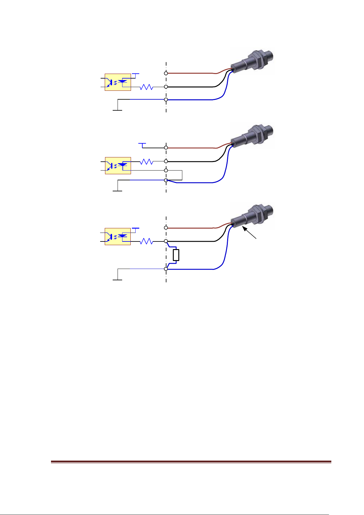
Figure 10
, (a) shows the connection of NPN type sensors. This connection is applicable for
input terminals X110 - X115 and X203 - X215 only.
Figure 10, (b) shows the connection of PNP type of sensors. This connection is applicable for
input terminals X310 - X315 only.
Figure 10, (c) this connection gives an alternative for PNP sensors to connect to NPN inputs.
However, the logic is inverse, so you must also change the logic in the corresponding setting
within Mach to also be inverse.
www.CNCRoom.com Page 13
Figure 10, Sensor connections

X203
X2
04
Y Home
Z Home
X Home
X
+
Limit
X-
Limit
Y
+
Limit
Y-
Limit
Z
+
Limit
Z
-
Limit
E
-
Stop
X211
0V
VCC
100 mA (max)
L
L
*
0V
24V
Ynnn
MB2 external circuit
5-30Vdc
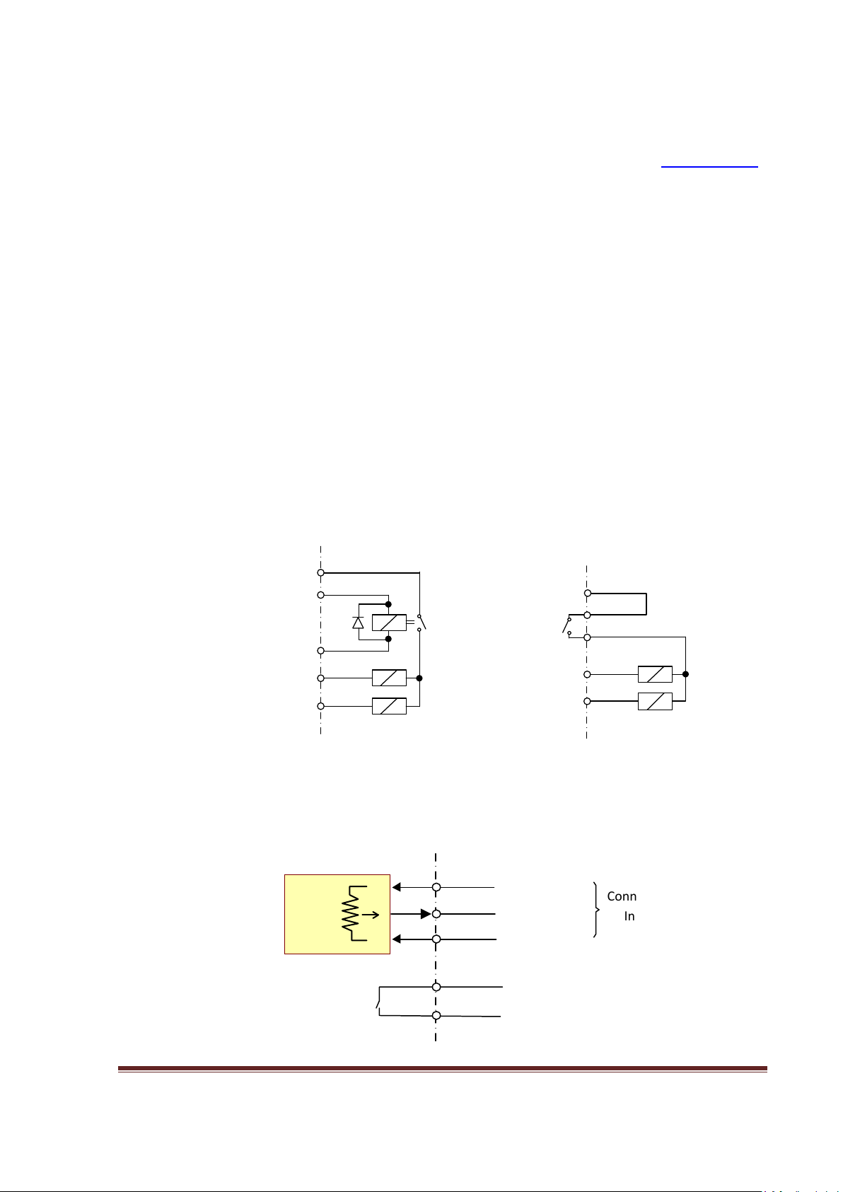
Figure 11, is an example of E-STOP, LIMIT and HOME switch connections
Figure 11
shows the conventional way to connect the Estop, Limit and Home switches. This
will form an “AND” circuit. Notice that all use NC contacts (normally closed).
Outputs
Transistor Sink Output
Figure 12, Output terminals
Figure 12
shows 14 output terminals, each output can sink current up to a maximum of
100mA with a total maximum of 500 mA per group of 7 outputs, as shown in Figure 1 on page
4.
External power supply
* A diode is needed in
MB2 External circuit
parallel with the coil
Figure 13, connecting various loads to a “Y” output
www.CNCRoom.com Page 14
Relays
NO2
CM2
SPD
24V
Yxxx
MB2v2.0
External circuit
Solder bridge *8
CP selected
24V
CP
24V
SPD
Yxxx
MB2v1.3 and v1.5
External circuit
MB2
AH
AO
AL
CM2
NO2
K2
+
-
AnaSpeed
circuit
The MB2 comes with two on-board relays, K1 and K2. Both provide NO or NC contacts. MB2
v1.5 or later, also provides an “OFF Delay” feature. To activate this feature the user needs to
follow the instructions as set out on on page 17, note *7 under the heading of Modifications.
These two relays are signal relays and should never be used as power relays. They are
intended to convey signals such as forward and reverse to a VFD (Variable Frequency Drive)
to control motor rotation of a spindle or similar. They can be used for other purposes as
well, and the user needs to map them in Mach accordingly. However, please take care, as
the contacts of these relays can carry a maximum current of only 0.5 Amps at 120VAC, or 1
Amp at 24Vdc. The user must use an external relay if the load requirements of the device
will exceed the aforementioned current rating.
Charge Pump
Charge pump is pulse frequency signal from Mach3/Mach4 indicating that Mach is present
and ready to run. MB2 has special circuit to capture this pulse frequency and output to CP
(Charge Pump) terminal. Normally an external relay would be connected to this CP terminal
for cutting the power source from any attached loads. However, in board MB2v2.0 the user
can choose to select K2 as an output for the CP signal. To choose this option, Please see
Figure 19, the underneath layout of the MB2. There is a blue arrow pointing to the appropriate
solder bridge, *8.
Figure 14, Charge pump interlock with other relays
Analog
5V or 10 V
Analog Output
0V
Connect to Forward
www.CNCRoom.com Page 15
input of VFD
Connect to Analog
Input of VFD

Figure 15, VFD connection
The “AnaSpeed” circuit converts PWM signal into an analog signal. The maximum voltage
level is dependent upon the external power supply. For example, if the circuit is connected to
a 0-10V analog input of the VFD, it will demand 10Vdc from the VFD as well.
The “AnaSpeed” has a tolerance margin of about ± 0.2V. It is able to generate a voltage up to
9.8V only (10V-0.2V) when supplied with external power of 10V. Compensation of this
margin can be done in the VFD’s parameters.
Normally, a VFD needs a forward command to rotate the motor. Thus, any NO contact of K1
or K2 can be used for this purpose.
OSSD Output and Safety Circuit
The MB2 has an OSSD (Output Signal Switching Device) output for the user to form a simple
safety circuit in their system. When the system is error free, the MB2 energizes the OSSD
output and it will de-energize the OSSD output if an error has occurred.
Most drives will give an OK signal or “Servo Ready” or similar, by energizing its appropriate
output and connected external devices will receive this status. The MB2 collects all OK signals
from various devices through terminal inputs X203 - X210 and then sends out an OK signal to
the next device.
However, if there is an error feeding in, MB2 will send out a “Not OK” signal by de-energizing
the OSSD output and the external safety circuit will cut power and stop the hazard.
Using a magnetic contactor as an external device is a simple way to disconnect the power
supply from the drives or the VFD. The “OVR“(Override) input is provided for temporarily
energizing the magnetic contactor, which lets the machine operator recover from the error.
To activate this function, the user needs to select one or more inputs from X203 to X210.
Then by creating a solder bridge across the appropriate corresponding solder pads, i203 to
i210, which are shown in Figure 18 on page 18, the chosen inputs will become part of the
safety circuit.
Figure 16 shows the safety circuit block and relevant I/O including, inputs, solder-bridge, and
override input and outputs.
Warning. The MB2 utilises only a simple safety circuit. There is no guarantee it will protect
against a serious external failure. It is therefore advised that the user MUST ALWAYS check
the functionality of any external circuit that is connected to the MB2.
www.CNCRoom.com Page 16
 Loading...