

CNC Hager Impressivo Instructions Manual
Instructions
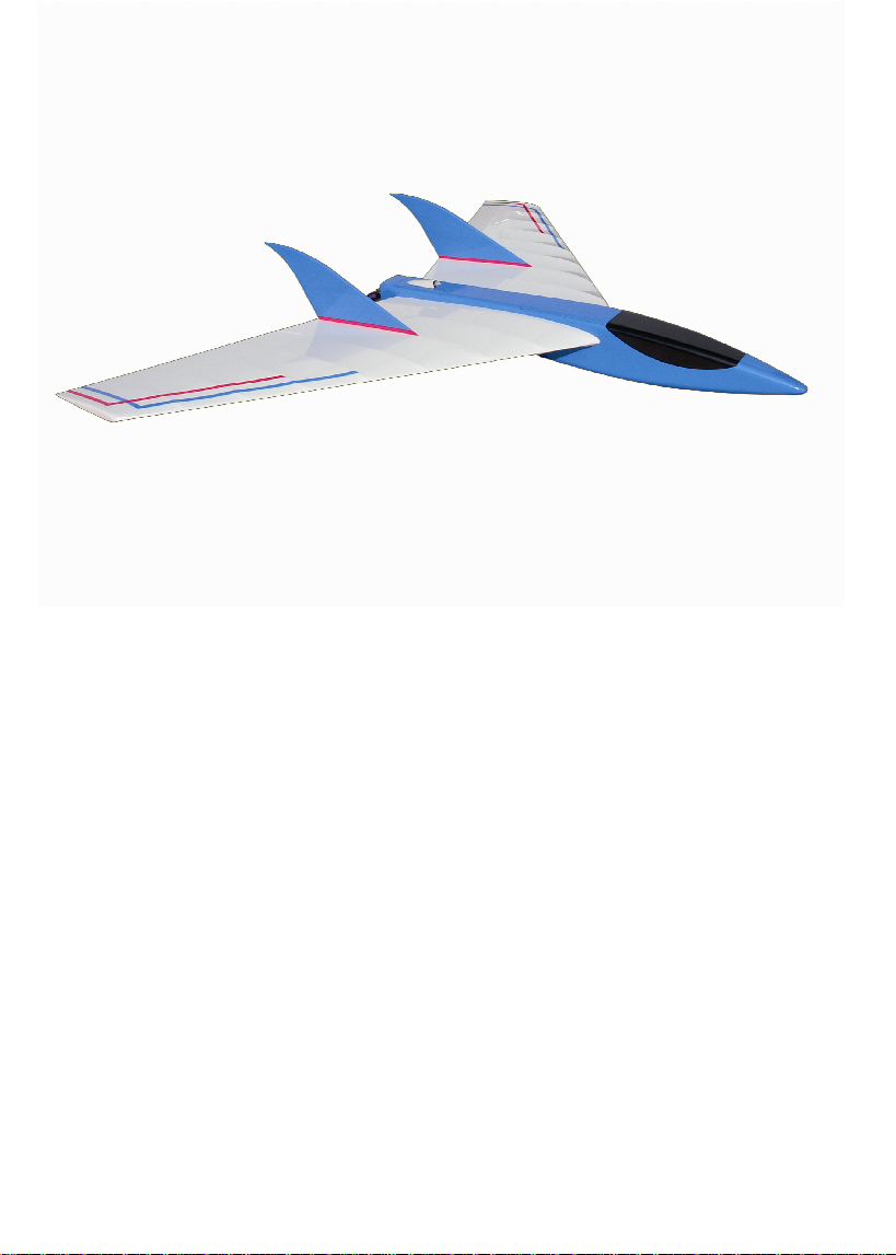
Impressivo
Thank you for the purchase of this product and congratulations, you've chosen
a quality product made in Germany out of the house CNC Hager.
Please read thes e instructions carefully before construction and proceed with building step by step.
General Information:
The Impressivo a Funmodell in wood construction in conjunction
with carbon fiber. It boasts a radical new look, CN C machined parts and large range
of speeds which can be flown both slow and very fast without losing in kindliness and
safe handling.
The wing rib is c reated in design and equipped with high Carbon Pipes.
A double hull bottom to ensure a clean battery cables and a pleasant change.
The instructions in this rudder deflections are given a basic setting for the first flights.
This can also be easily adapted to its own fiscal habits.
Construction: ribs , sides, ribs and ridges are dovetailed with each other and thus make it
much easier to ensure the development of the model.
For sufficient stability at high speeds The large-sized Carbon Spars in the wings.
The test models were covered with Oracover.
Tested Drive and RC:
Motor : MEGA 16 / 15 / 3
Battery : 3S Kokam 2100mah 30C
Regulator : 40A
Prop : 4,7 x 4,7 CAM Speed
Receiver : Schulze Delta 535
Servo : Graupner DES 427 BB Digital
All rights reserved. Reproduction and commercial use of these instructions are not allowed.
For consequential damages that may result from the operation of our model aircraft,
will assume no liability. Changes of parts or materials shall be carried out at its own discretion.
The information referred to in this assembly guide accessories, radio gear and the drive are
only recommendations.
1

A
R2
R3
R1
B
R24
R1
C
R1
D
R4
R5
R6
R7
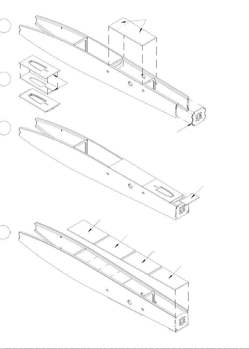
2

Hull Structure
A - C
- In building the fuselage side panels ensure that occur right
and left halves.
- The lower Square bar R1 (balsa bar 4x4) flush
along the outer edge on the side panel stuck R2,
ensure to watch on left and right halves.
- Doubler R3, and adapt the body with viscous
superglue to the R2 side part glue.
(The carbon pipes take R24 to help)
- The remaining torso straps R1 on the side panel R2 stick.
- The side panels using the Carbon pipes together R24 and
the fuselage contour sanding down slightly.
D
- To facilitate the insertion of the ribs, you should buff the edges.
So this way the body R3 is not damaged.
- The fuselage with the ribs R4, R5, R6 and the previously
composite floor part R7 stick them together.
- 1mm holes of R5 and R6 show up (cover).
- Focus on a level surface.
The bottom part of first serves to the exact angle of
Bulkhead to reach R4, so the trunk is the bonding
not oblique warped.
- Later, after completion of the trunk of the soil at the
perforated line is disconnected in order to move
the cable forward in the fuselage nose to.
- Joists and base together.
3
R8
A
B
R10
C
R9
R11
R15
D
R14
R13
R12
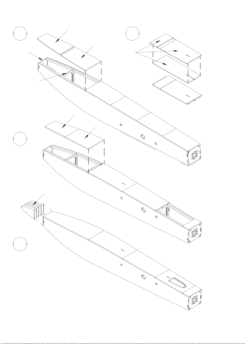
4

A
- Cover of both R8 (Balsa 2mm) together with the
Hull clog, the middle between the ribs R5 and R6.
(ensure that the lid is stuck)
- Motor frame paste R9.
B
- Cover composed of both R10 (Balsa 2mm) (Figure B).
This cover is required for step C.
C
- Cover R11 use R10 cover stick.
D
- Bottom parts R12 - R15 (Balsa 2mm) in order from
stick back to front.
- Beginning with R12 make sure that R12 is sitting,
so that the angular deviation to the front is not too large.
5
A B
R19
R17
C
R18
R20
R16
R22
R21
R23
D
6
 Loading...