

CNCDIY CNC 6040 User Manual
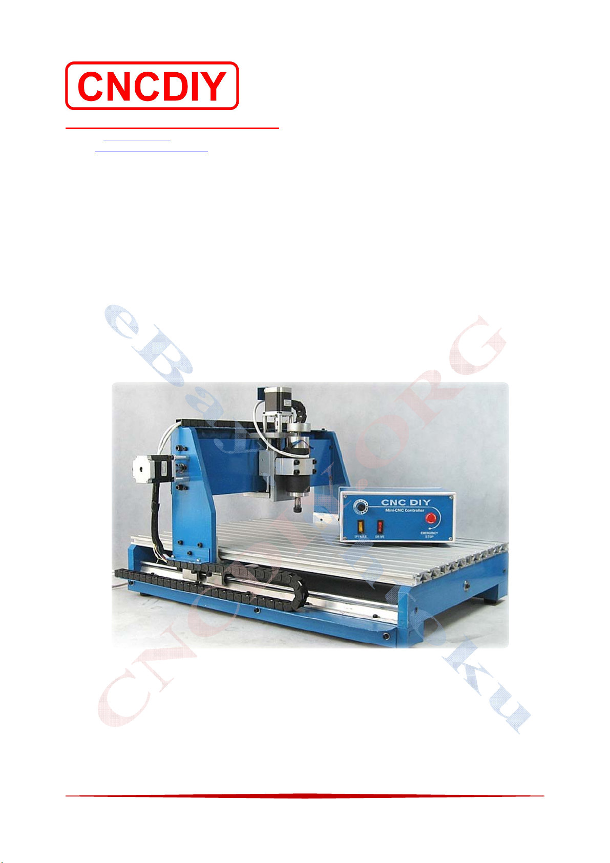
CNC 6040 Router / Engraver System
CNCDIY CNC Routing Machines System User’s Manual
CNCDIY CNC Routing Machine System
Website: www.cncdiy.org
Email: cncdiy_selling@ymail.com
CNC 6040
ROUTER / ENGRAVER / DRILLING / MILLING MACHINE
User’s Manual
Latest update: 9 September 2009
1

CNC 6040 Router / Engraver System
CNCDIY CNC Routing Machines System User’s Manual
Copyright
© 2010 CNCDIY CNC Routing Machine System. All Rights Reserved.
Declaration
z Although, the routing machine system is produced by CNCDIY Routing Machine System, it
cannot be called a real commercial product. The user must require having relative knowledge
about mechatronics. All matters concerning the machinery, electronics, computer equipment,
are likely due to improper use or a virus, software compatibility reasons, result in failure, this
failure may cause a certain degree of risk and economic losses. CNCDIY Routing Machine
System does not bear the direct and indirect losses corresponding responsibilities.
z Any routing machine you purchased from CNCDIY Routing Machine System is only paid
for the price of the machine and relative device itself only, does not included any software
and software training costs. You can follow this "User’s Manual" learning how to operate or
through the network under the guidance from our staff. Each routing machine system is
operation normally after a standard test produce to identify the three-axis can be controlled
and able to run imported tool path properly. This recognition of our work is completed. All
the software training is not in our capacity. CNCDIY Routing Machine System is a vast
CNC-DIY enthusiast platform, we are very happy in our own knowledge, ability and time to
give novices within reach of as much as possible help, but please do not use these to help and
look at the FAQ to make is that we have obligations.
z Software copyright: This machine does not come with any software, operational use, and
covered in this guide are all related software from the Internet, the original author enjoys
copyright to the author's official Web site at your own download a trial version or purchase
licensed software, because not authorized the use of for all damage caused by the software
and legal issues from the users themselves.
2

CNC 6040 Router / Engraver System
CNCDIY CNC Routing Machines System User’s Manual
Reminder
z The machine uses a parallel interface and control computer connected through the parallel
port control software MACH3 controlled carving machine to run the various axes in
accordance with instructions, make sure you prepare for the routing machine control
computer has a parallel port, and the required work in EPP parallel port mode, any other
mode may result in engraving machine cannot operate normally, the EPP mode is set to be
carried out in the computer motherboard BIOS, all manufacturers to set methods vary, please
refer to the instructions to set up your computer. Part of the desktop computer does not have
built-in parallel port, users can be purchased parallel port PCI expansion card slot to use. But
any commercially available USB-parallel port adapter does not allow normal operation of the
machine
z Controlling the computer should be dedicated and, if possible do not install other
applications software; do not recommend the use of laptop computers to control the
engraving machine, part of the notebook computer's battery-saving chip may interfere with
the pulse signal, some parallel port voltage is low, may lead to pulse signal is lost the use of
engraving machine could not be properly controlled.
Warning
z The machine system is to rely on related software control, the need for the right software
settings in order to function properly, in the absence of fully recognized under the temerity to
set the correct test machine loaded knife can be dangerous or permanent damage to
machinery. During the software installation and settings, do not open the control box power
supply, in order to avoid malfunction causing damage.
z Do not at any time the power electronic control box connected to the case, pulling the plug
inserted above the line terminal; spindle power each time you open the speed control knob
must be transferred before the low-end office and then start-up; both spindle switch or driver
switches repetition interval of the switch at least once every 30 seconds or more; not pay
attention to the above questions is likely to cause some damage control circuits.
z As the use of the AC110V or AC220V voltage, power state, do not open the electronic
control cover, do not touch the spindle motor terminals, operation of the spindle motor driven
high-speed rotary cutting tool, do not touch, and a closer look at sculpture, the working must
be worn goggles or protective masks! The operator must wear a protective mask and a
goggle.
3

CNC 6040 Router / Engraver System
CNCDIY CNC Routing Machines System User’s Manual
Warranty
All electrical products manufactured or marketed by CNCDIY Routing Machine System has a
warranty period of 6 months from the day they are shipped out of our warehouses. The electrical
products are included CNC driver and DC spindle driver only and the VFD driver is not included
The mentioned warranty covers repair material and labor costs, at CNCDIY Routing Machine
System facilities, incurred in the repair of the products.
Within the warranty period, CNCDIY Routing Machine System will repair or replace the
products verified as being defective. The purchaser must send the damaged or broken part back
to Hong Kong office of CNCDIY Routing Machine System after providing photos to show the
damage part and proving the causes of the problem to our staff.
It is entirely up to CNCDIY Routing Machine System to determine whether a repair is to be
considered under warranty.
4

CNC 6040 Router / Engraver System
CNCDIY CNC Routing Machines System User’s Manual
Contents
Chapter 1 Introduction 4
Chapter 2 Safety and Protection 4
2-1 Gloves 4
2-2 Handling Posture 4
Chapter 3 Hardware Installation 7
3-1 Installation Precaution 7
3-2 Understanding of Your Machine System 8
3-3 Machine Specifications 9
3-4 Spindle (D57 and C57) Specifications 10
3-5 Stepping Motor Specifications 11
3-6 Components Check 12
3-7 Tools and Materials Requirement 13
3-8 Machine Installation 15
3-9 Electrical Connection 20
3-10 Basic Testing with CNC Control Box 25
Chapter 4 Installation of Mach 3 Software 27
4-1 Connect to the CNC Control Box 27
4-2 Basic Setting of Mach 3 software 27
4-3 Stepping motor setting in Mach 3 with different coupling type 32
4-4 Load a G code file 34
4-5 Testing with CNC machine 35
Chapter 5 Installation of EMC2 Software 36
5-1 Connect to the CNC Control Box 36
5-2 Basic Setting of EMC2 software 36
5-3 Stepping motor setting in EMC2 different coupling type 39
Chapter 6 Test Your System 42
5
CNC 6040 Router / Engraver System
CNCDIY CNC Routing Machines System User’s Manual
Chapter 1 Introduction
Thank you for your selection of our product. We have provided CNCDIY routing machine
system, also very honored that you have the time to read, prepared by the Walter, "Quick Start
Guide" in the hope of its initial contact with routing machine will be able to help! This is not a
company. We are formed from some CNC lovers in different Places and hope provide some low
price and high quality DIY CNC machines for you!
We hope to provide some low price and high quality DIY CNC machines for you! All of our
machine set are included a CNC Machine body with 3 Stepping Motors, a CNC controller, a 24V
Switching Power Supply and a Driller. Each machine set is installed completely and pass testing
before shipping, users can use the machine immediately when received.
Chapter 2 Safety and Protection
Before you open the packages and check the machine parts, please care about the following
items
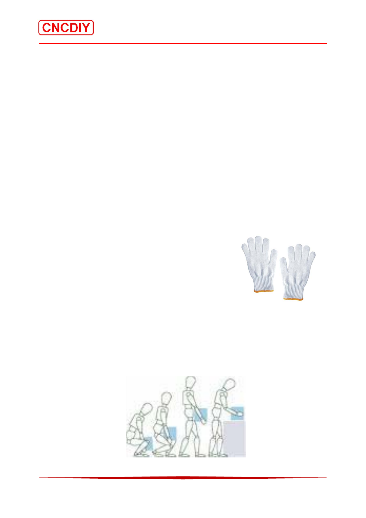
2-1 Gloves
Your hands are easy hunt by the sharp edges of the parts and the
packages. The Gloves can reduce the risk for your hands!
2-2 Handling Posture
Some of parts are heavy, when you move or put up them, please be careful and take care you
body with good Handling Posture
“LIFTING - PUSHING - PULLI NG – LOWERING”
6

CNC 6040 Router / Engraver System
CNCDIY CNC Routing Machines System User’s Manual
Chapter 3 Hardware Installation
3-1 Installation Precaution
The CNC Routing Machine system contains numerous delicate electronic circuits and
components which can become damaged. Prior to installation, carefully read the user’s manual
and follow these procedures:
z When connecting hardware components to the connectors of the Control system, make sure
they are connected tightly and securely.
z Before using the product, please verify that all cables and power connectors of your
hardware components are connected
z Before unplugging the power, make sure the power supply voltage has been set according to
the local voltage standard.
z Do not place the machine system on an uneven surface.
z Do not place the machine system in a high-temperature environment.
z Turning on the control system power during the installation process can lead to damage to
system components as well as physical harm to the user.
z If you are uncertain about any installation steps or have a problem related to the use of the
product, please consult a certified computer technician.
z The main material of the routing machine is used aluminum alloy, cannot be used due to
any inadvertently fall or collision to damage the machine. Please placed the routing
machine system in a firm, stable, level of desktop, thin desktop will result in a greater
resonance in the noise during the machine running.
z Electric control box is installed well with a switching power supply, a stepper drive
controller and a spindle power driver. Please place it in the level of ventilation. Electric
control box cannot have electromagnetic interference within around 10 meters. Please also
care about wrestling and fear flows effect!
z Remember to tidy up the wiring harness, messy take place. It is likely to impede the normal
movement of the routing machine. Please consider the stroke area for the moving gantry
and any sliding part with sufficient margin of the wiring harness.
7

CNC 6040 Router / Engraver System
CNCDIY CNC Routing Machines System User’s Manual
3-2 Understanding of Your Machine System
For the future use and maintenance, user should understand your routing machine system first.
The major parts are shown in below figure and include a set of routing machine, a CNC control
box, spindle with bracket, and an attachment box. The attachment box is included 4 sets of platen,
5 of basic tooling, a pair of brushes for spindle replacing, a pair of spindle handles and a Hex
wrench and some screws. (Note: The screws are attached to a few random, different parts may
require different lengths and types of screws, is depending on the actual needs of their own,
separately purchased locally)
ZAxis
Stepping
CableChain
Motor
YAxis
Stepping
Motor
XAxis
Stepping
Motor
Working
Tabl e
CNCRoutingMachine
Spindle
CNCControlBox
8

CNC 6040 Router / Engraver System
CNCDIY CNC Routing Machines System User’s Manual
3-3 Machine Specification
CNC6040 Router / Engraver System
1. Effective Travel: 400mm(X) * 580mm(Y) * 60mm(Z)
2. Machine Outside Dimensions: 850mm * 640mm * 470mm
3. Maximum Workpiece
750mm*480mm*90mm
Dimensions:
4. Working Table Dimensions: 750mm*480mm*20mm
5. Sliding Units:
i) X Axis Dia. 16mm Guide
ii) Y Axis Dia. 20mm Guide
iii) Z Axis Dia. 13mm Guide
6. Driving Units: New Ball Bearing (BB) 1605
7. Coupling Plum Coupling / Simple Coupling
8. Stepping Motor Type: 57 Two-Phase 1.45A~2A (New)
9. Main Materials of Machine Aluminum Alloy 6061
10. Actual carving precision: 0.08mm (carving different hardness materials vary)
11. Repeat positioning accuracy: 0.06mm
12. Engraving speed: 0 ~ 2000mm/min
13. Machine weight: 53KG (excluding packaging)
14. Acceptable Processing
PVC, PCB, Plastic, Woods, Brass and Aluminum
materials
Driving Units
The diffient type of driving units are using on X, Y and Z axis for the smooth driving unit! The
basic information is shown below:
Model Ball Bearing Screw
Axis Name
Diameter(mm)
Pitch(mm)
X Y Z
16 16 16
5 5 5
9
CNC 6040 Router / Engraver System
CNCDIY CNC Routing Machines System User’s Manual
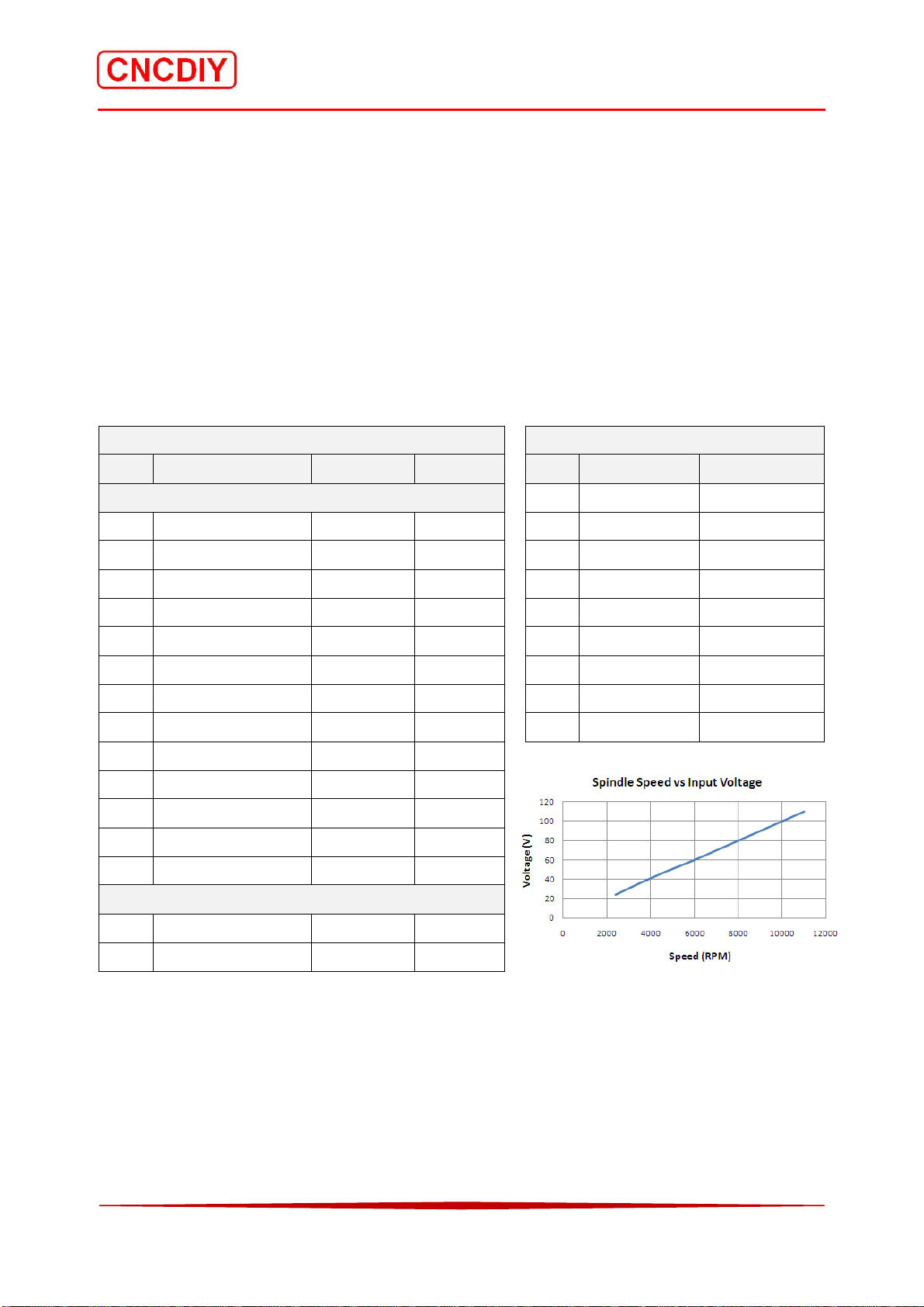
3-4 Spindle (D57 and C57) Specifications
The spindle is a used of ELECTROCRAFT E240 motor installed an ER11 chuck and a Plastic
Cooling Fan. The original is a DC servo motor, it is a waste and the encoder has been damaged.
This is a good choice and environmentally friendly for using the small CNC.
The ER 11 chuck is using with tooling diameter of 3.175mm. It can reduce the radial runout and
increasing the routing Precision to 0.03mm. The ER 11 chuck is included two handles for
locking the cutting tools.
Specification Speed Vs Voltage
Seq. Description Details Unit Seq. Voltage (V) Speed(rpm)
A. Motor
1 24 2400
1 Voltage Range 24 – 110 V 2 36 3500
2 Rated Power 200 W 3 48 4700
3 Peak Torque 1.7 Nm 4 60 6000
4 Stall Torque 0.22 Nm 5 70 7000
5 Peak Current 24.5 Amps 6 80 8000
6 Stall Current 3.1 Amps 7 90 9000
7 Radial Load 4.5 kg 8 100 10000
8. Axial Load 2.3 kg 9 110 11000
9. Voltage Constant 7.8 V/kRPM
10. Diameter 57 mm
11.
12
AxialDiameter
Axiallength
8 mm
42 mm
13 Weight 1.1 kg
B. ER Chuck
1. Hold Diameter 3.175 mm
2. Precision 0.03 mm
10
CNC 6040 Router / Engraver System
CNCDIY CNC Routing Machines System User’s Manual
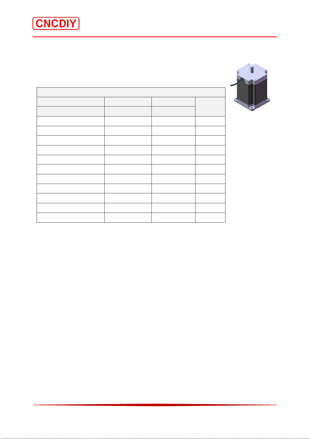
3-5 Stepping Motor Specifications
The stepping motors are selecting the new Chinese stepping motors or used
Japanses and USA stepping motors.
Specification
Machine Model CNC3040 CNC3020
Stepping Motor Model 57BYGH218 Not fixed
Step Angle 1.8 1.8 (deg)
Motor Length 51 N/A (mm)
Rate Voltage 2.6 2.6 (V)
Rate Current 2 2 (A)
Phase Resistance 1.3 N/A
Phase Inductance 4 N/A (mH)
Holding Torque 9 N/A (kg.cm)
Lead Wire 4 N/A (NO.)
Rotor Inertia 275 N/A (g.cm2)
Detent Torque 0.36 N/A (kg.cm)
Motor Weight 0.65 N/A (kg)
Unit
(Ω)
11

CNC 6040 Router / Engraver System
CNCDIY CNC Routing Machines System User’s Manual
3-6 Components Check
A check listed is shown in Figure 3.6 below. Please check them with your received components
and pull a tick or an across for record.
Figure 3.6 Components Chec k List
Items Qty
Parts
Number
Received
Remarks
or not?
A .Stepping Motor Part
1. 57 Type Stepping Motor 3 S01
2. Plum Coupling 3 S02
3. Stepping Motor Support 12 S03
4. Knob 3 S04
5.Chain Support (For Z axis only) 1 S05
6. Crank Bolt M5 60mm 12 SB01
7. Bolt M5 6.5mm 1 SB02
8. Bolt M3 4mm 2 SB03
E. Spindle Part
1.D57 Spindle 1 S01
2.D57 Spindle Bracket 1 S02
3.ER11 Chuck 1 S03
4.ER 11 Head 1 S04
5.Crack Bolt M8 60mm 4 SB01
6. Top Handle 1 SH01
7.Bottom Handle 1 SH02
Items Qty
Parts
Number
Received
Remarks
or not?
F. Accessories Parts
1. Control Box CB001 1 N/A
2. A39773XB001 1 N/A Installed in CB001
3. Cutting Tools CTS001 1 N/A
4. Parallel Port 1 N/A
12

CNC 6040 Router / Engraver System
CNCDIY CNC Routing Machines System User’s Manual
3-7 Tools and Materials Requirement
In this chapter, there are discuss the major tools for the assembly work!
Figure 3.7 Tools list
A. Mechanical Part
Tools Name Description Picture
Processing
Platform
Frame Level
Dial Test
Indicator
Calliper
The Processing platform is an important for
assembly. A Processing platform can make
sure the machine table is level.
1. The best is metal Processing platform.
2. Any level plate or platform can also be
used such as metal plate /table or wood plate
/table.
The frame level use to measure the working
table, Horizontal and vertical parts
Measures displacement at an angle of a lever
or plunger perpendicular to the axis of the
indicator. A regular dial indicator measures
linear displacement along that axis.
Measure the distance between two
symmetrically opposing sides.
Height Gauge
Square ruler
Hexagon keys
Screwdriver
Measure vertical distances. The pointer is
sharpened to allow it to act as a scriber and
assist in marking out work pieces.
To measure the right angle when you
assembling the Gantry Frame Part and the
Base Part.
The Metric Hexagon keys are the main
assembly tooling! The long armtypeofthe
Hexagon keys is most useful and save your
energy! The sizes are from 1.5 to 10.
The flat and crosshead types of screwdrivers
are needed. The electric screwdriver is highly
recommended!
13
CNC 6040 Router / Engraver System
CNCDIY CNC Routing Machines System User’s Manual
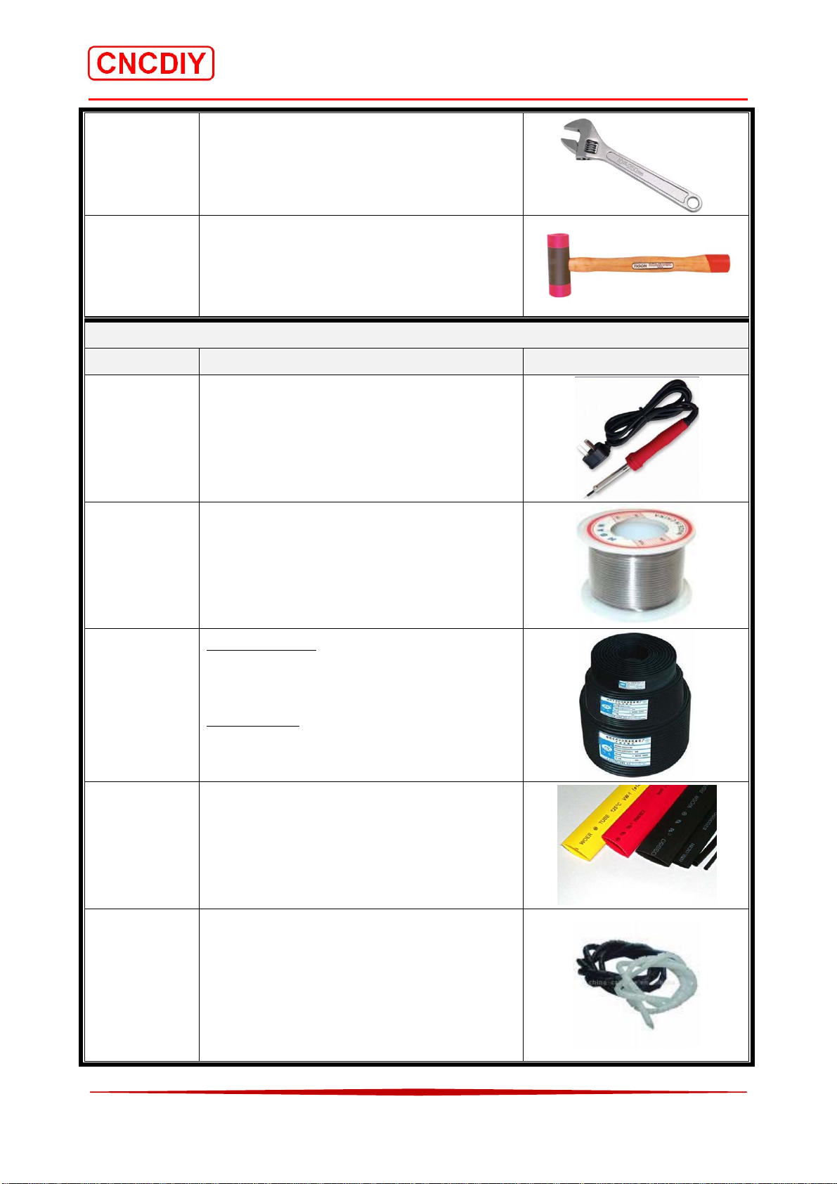
Spanner
Hammer
The nuts and crank bolts installation
The small adjustment and part assemble!
(Plastic)
B. Electrical Parts
Tools Name Description Picture
Soldering
iron
To melt the solder for wire connection.
The best power range is between 30W~
60W.
Soldering Tin
To melt to join wire cable
Power Cable
300/300V
HeatShrinkable
plastic
Spiral
Wrappings
1. 4 wires Cable
Model RVV4*1
Length: 5.9m (19.4ft)
2 wires Cable
Model RVV2*1
Length: 3.1m (10.2ft)
To protect the wire’s join
The recommended sizes are 3mm and 5mm
To protect the cable
The recommended inside diameter are 5mm
and 8mm
14
 Loading...