

Page 1

E2 User Manual
E2- ROUTER INTERFACE BOX Rev. 1
User manual Rev. 1
1. Overview
This unit provides speed control on a router, on/off on router and vacuum or
coolant, connector for limits & home, built in safety charge pump, and
buffering of all I/Os.
It is designed to go between an existing controller and the PC. So wiring is
very simple. This way you can add the feature with our having to rewire the
control that is working Ok.
Revision: 10/21/2010 http://cnc4pc.com/TechDocs/ E2R1_USER_MANUAL.pdf 1/10
Page 2

E2 User Manual
2. Features
IEEE 1284 Standard compatible.
Includes the circuitry
recommended by the IEEE 1284
Level 1 standards for bidirectional
parallel communications between
personal computers and
peripherals.
DB25 connector to connect the
stepper motor driver board. This
connectors uses only pins 2-9.
Microcontroller based SCHP.
This board comes with a
microcontroller that allows the
implementation of a complex
algorithm for sampling and
analyzing the SCHP signal.
AC plugs for router and vacuum
or coolant pump.
Speed Control Signal Can Be
PWM or 0-25HZ Pulse Stream.
Speed Control can go from 30 to 100% of
the router’s rated speed.
Works with 110 or 220VAC at 60
or 50 HZ.
For 2.5HP or 1800 Watt Routers.
Buffered inputs and outputs.
Outputs are buffered through the
use of high speed and high
current buffers allowing the card
to output the signals without using
the power from the parallel port. It
can take the +3.3 or +5vdc signal
from the parallel port and deliver
solid +5vdc at 24 milliamps.
• Connector for Limit and Home
Switches. A C16 – Index & Home
Board or a custom cable with
switches or sensors can be
connected.
Works directly with popular
CNC hardware and software.
Such as Geckodrive G540,
Xylotex, HobbyCNC, Rockcliff, or
Rutex, and parallel port control
software, such as mach2, Linux
EMC, TurboCNC, CNCPlayer,
CNCZeus and others. (Not all
tested).
All TTL 5VDC signals. Interface
directly with parallel port interface
products and other CNC4PC
cards. 5VDC (TTL) cards are very
common among automation
devices.
Revision: 10/21/2010 http://cnc4pc.com/TechDocs/ E2R1_USER_MANUAL.pdf 2/10
Page 3

E2 User Manual
3. Specifications.
This box is based on the C33 – Router Multifunction Interface Board. For specifics,
please check the board’s manual:
http://cnc4pc.com/Tech_Docs/C33R1_1_User_Manual.pdf.
4. Configuration Steps:
1. Connect the cable as shown below:
Fig. 1.
Revision: 10/21/2010 http://cnc4pc.com/TechDocs/ E2R1_USER_MANUAL.pdf 3/10
Page 4

E2 User Manual
Fig. 2.
Revision: 10/21/2010 http://cnc4pc.com/TechDocs/ E2R1_USER_MANUAL.pdf 4/10
Page 5

E2 User Manual
5. Configure the Safety Charge Pump:
For Configuring the Safety Charge Pump in Mach X: Use the dialog window
Config / Ports and pins / Output Signals. Enable the Charge Pump output and
assign it to pin 17. Press the apply button.
Fig. 3. Charge Pump configuration
Selecting the SCHP operation mode.
The Safety Charge Pump can be
activated or deactivated by
moving the jumper position.
Revision: 10/21/2010 http://cnc4pc.com/TechDocs/ E2R1_USER_MANUAL.pdf 5/10
Page 6

E2 User Manual
6. Configure the Relays:
Assign two outputs to pins 1 and 16. Pin 1 controls the router and pins 16
controls the coolant.. Use the dialog window Config / Ports and pins / Output
Signals. Enable the two outputs and assign them to pins 1 and 16. Press the apply
button.
Fig. 4
Assign the two outputs to the Spindle and Food Relay. Use the dialog window
Config / Ports and pins / Spindle Setup. Make sure you uncheck the “disable
relays” box and assign the outputs to each relay. Press the apply button.
Fig. 5
Revision: 10/21/2010 http://cnc4pc.com/TechDocs/ E2R1_USER_MANUAL.pdf 6/9
Page 7
E2 User Manual
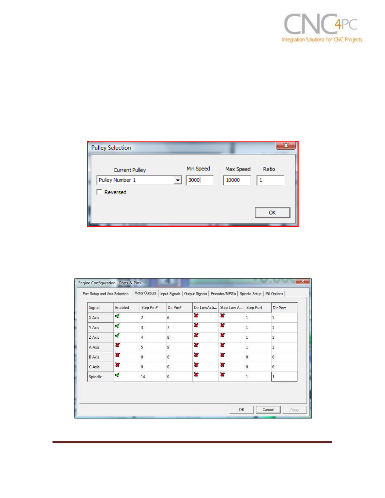
7. Configure the Speed Control:
Set the speeds that you expect for the spindle. Use the dialog window Config /
Spindle Pulleys. Remember that the min speed is 30% de value of the max speed.
If the router has a speed control knob, make sure to set it to the max speed. Press
the apply button.
Fig. 6
Set pin 14 for sending the pulse stream. E Use the dialog Config / Motor
Outputs. Enable the spindle and assign pin 14 for step.
Revision: 10/21/2010 http://cnc4pc.com/TechDocs/ E2R1_USER_MANUAL.pdf 7/9
Page 8

E2 User Manual
Set the frequency the box is going to work on (50 or 60Hz) and the desired
control method (PWM or Step and Direction).
The spindle can be controlled with PWM or Step and Direction. Use the dialog
window Config / Ports and pins / Spindle Setup. Under Motor Control select PWM
or Step and Direction. Instructions will be given for both control methods. Just
make sure whatever you select in the control software must match the jumper
position on the board. Press the apply button.
Set the jumper to select the appropriate control method, it can be PWM or step. If
using PWM play with different PWM Base frequencies, to up to 10,000. Leave the
one that works better for the setup.
Revision: 10/21/2010 http://cnc4pc.com/TechDocs/ E2R1_USER_MANUAL.pdf 8/9
Page 9

E2 User Manual
If using step and direction tune the spindle to go at max speed. Use the
dialog window Config / Motor Tuning / Spindle. Set velocity and acceleration to the
maximum value. Step length to 3..
Revision: 10/21/2010 http://cnc4pc.com/TechDocs/ E2R1_USER_MANUAL.pdf 9/9
Page 10

E2 User Manual
LIMIT SWITCHS CONNECTOR
RJ45 PIN
DESCRIPTION
CONTROLLER PINS
1
GND
2
Z HOME/LIMIT
Port 1 Pin 11
3
Y HOME/LIMIT
Port 1 Pin 12
4
X HOME/LIMIT
Port 1 Pin 13
5
NOT USED
6
NOT USED
7 5V
8
NOT USED
Wiring the Limits:
Disclaimer:
Use caution. CNC machines could be dangerous machines. DUNCAN USA, LLC
or Arturo Duncan are not liable for any accidents resulting from the improper use of
these devices. The C33 is not fail-safe device, and it should not be used in life
support systems or in other devices where its failure or possible erratic operation
could cause property damage, bodily injury or loss of life.
Revision: 10/21/2010 http://cnc4pc.com/TechDocs/ E2R1_USER_MANUAL.pdf 10/9
 Loading...