

Page 1

User’s Manual Page i
USER’S
MANUAL
VER.1
C80- EXPANSION BOARD
Rev. 1
OCTOBER, 2017
Page 2

User’s Manual Page ii
USER'S MANUAL
TABLE OF CONTENTS
Contents Page #
1.0 OVERVIEW ..................................................................................................................... 1
2.0 FEATURES ..................................................................................................................... 1
3.0 SPECIFICATIONS .......................................................................................................... 2
4.0 BOARD DESCRIPTION .................................................................................................. 2
5.0 SPECIFICATIONS .......................................................................................................... 3
5.1 Power Requirements ................................................................................................. 3
6.0 POWER TERMINAL ....................................................................................................... 3
6.1 Enable pin. ................................................................................................................. 4
7.0 LED INDICATOR ............................................................................................................ 4
8.0 PINOUT ........................................................................................................................... 5
8.1 Pin Numbering ........................................................................................................... 5
8.2 IDC26 ................................................................ .......................................................... 5
9.0 CONFIGURATION JUMPERS ........................................................................................ 6
9.1 Using the COM configuration jumper ....................................................................... 6
10.0 EXAMPLE WIRING optoisolated output ....................................................................... 6
10.1 Wiring board .............................................................................................................. 6
11.0 WIRING DIAGRAMS ....................................................................................................... 7
11.1 Connecting Switches or push button. ...................................................................... 7
11.2 Connecting NPN sensors. ......................................................................................... 8
11.3 Connecting in parallel NPN sensors. ....................................................................... 8
11.4 Connecting PNP sensors. ......................................................................................... 9
12.0 DIMENSIONS ................................................................................................................ 10
Page 3

User’s Manual Page 1
1.0 OVERVIEW
This card provides an easy way to connect your inputs and outputs from your port using
a LPH26pin Ribbon Cable or parallel port. Provides terminals for connections and
conditions signals for use in CNC applications.
2.0 FEATURES
• Terminal Block for all I/Os.
• Expansion port for Mother Board. Connect the C76 or ESS expansion board.
• Open collector Outputs pins optoisolated 2, 3, 4, 5, 6, 7, 8, 9, 1, 14, 16, 17.
• Input pins 10, 11, 12, 13, 15.
• Terminal Block input with close by ground or +5VDC connections, COM and
outputs with + 24VDC and ground
• Screw-On connections for all terminals. You only have to screw-on the wires to
make all your connections.
• Status LEDs for enable.
• Fully Optoisolated Inputs and Outputs.
• External Enable Pin
Page 4
User’s Manual Page 2
3.0 SPECIFICATIONS
DIGITAL INPUT SPECIFICATIONS
On-state voltage range
12 to 24V DC
Maximum off-state voltage
0.8V
Maximum operation frequency
4 MHz
Typical signal delay
10nS
DIGITAL OUTPUT SPECIFICATIONS
Maximum output voltage
(24V power supply voltage) +
0.5V
Typical output current
500mA
Maximum operation frequency
4 MHz
Typical signal delay
0.25 µS
Time of transition to high impedance state
12 s*
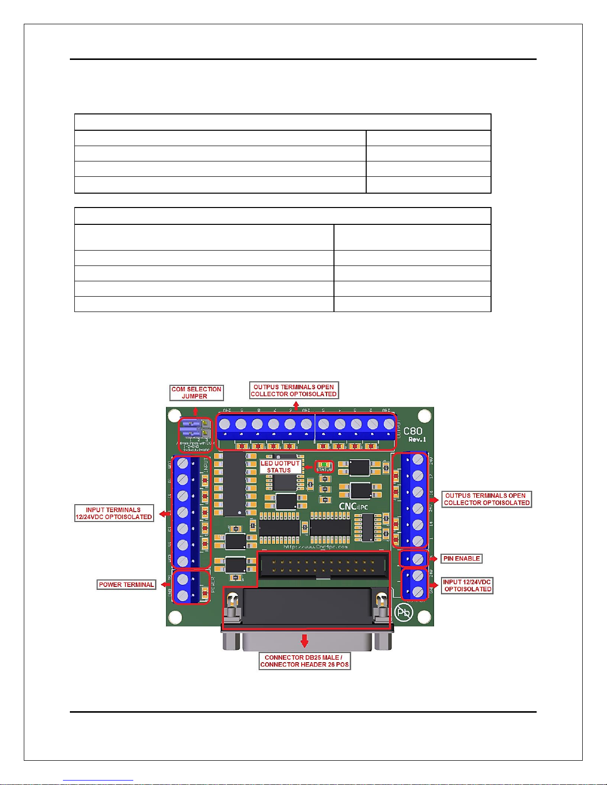
4.0 BOARD DESCRIPTION
Page 5

User’s Manual Page 3
5.0 SPECIFICATIONS
5.1 Power Requirements
Regulated +5VDC and +12/24VDC is required to power this board.
WARNING
Check the polarity and voltage of the external power source and connect the 5VDC and
GND. Overvoltage or reverse-polarity power applied to these terminals can cause
damage to the board, and/or the power source.
6.0 POWER TERMINAL
To preserve optoisolation two independent power sources should be used. A +5vdc to power
the optos that interact with the controller (which could be a USB cable) and a +24vdc at 200
Amp to power the board..
Note. It can be polarized by Pin 26 of the IDC26
Page 6

User’s Manual Page 4
6.1 Enable pin.
The card must be provided with a 24VDC signal to enable operation. This feature has
been added to externally control the status of the outputs. An external switch or a Safety
Charge Pump can be added to provide the enabling signal. If this function is not
required, a jumper can be placed between 24VDC and the EN terminal.
7.0 LED INDICATOR
The power LED lights indicate that the system is ready but disabled. When Status LED,
(Green LED) lights, it indicates that the system is enabled.
Page 7
User’s Manual Page 5
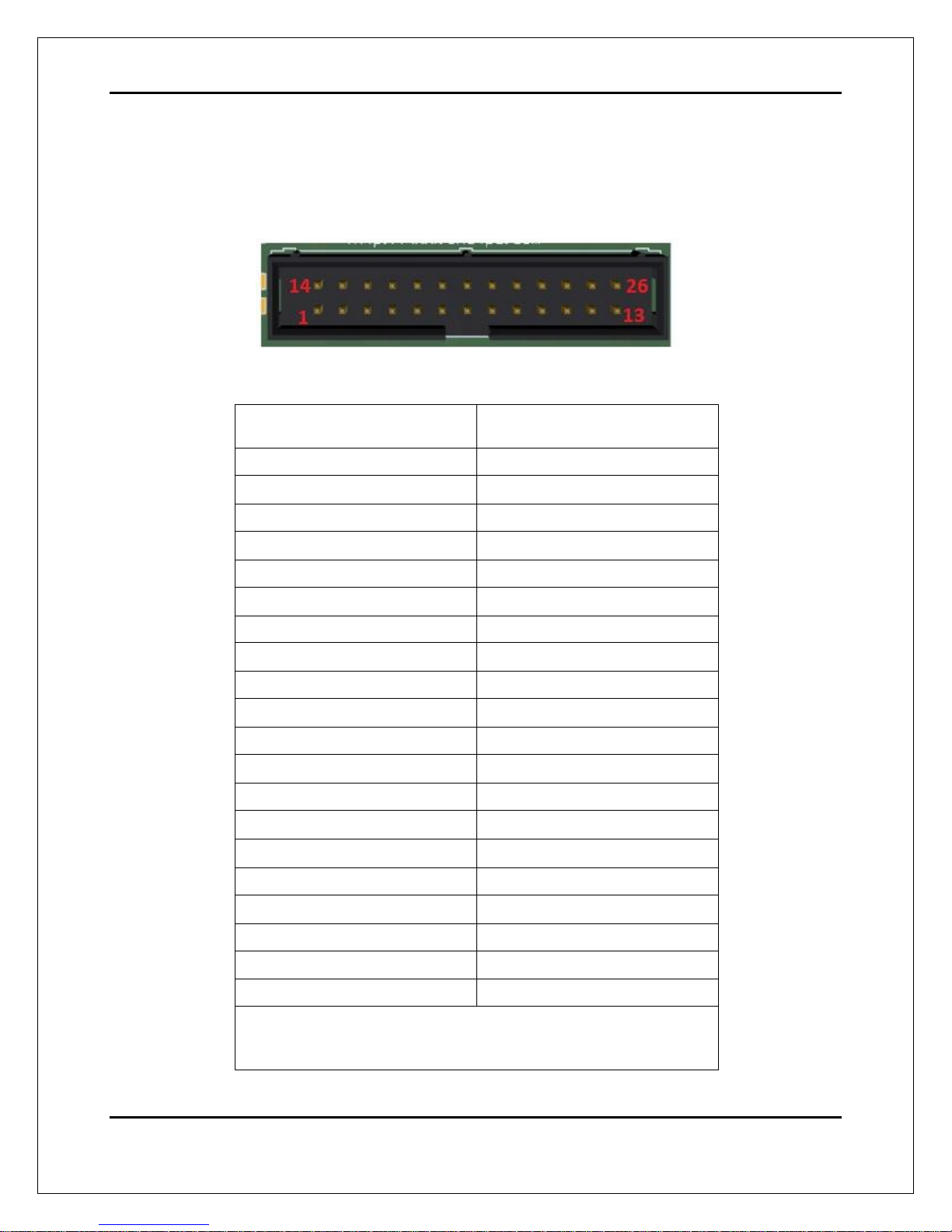
8.0 PINOUT
8.1 Pin Numbering
26-PIN
8.2 IDC26
IDC26 Pin number
LPT port direction signal
1
Output 1
2
Output 2
3
Output 3
4
Output 4
5
Output 5
6
Output 6
7
Output 7
8
Output 8
9
Output 9
10
Input 10
11
Input 11
12
Input 12
13
Input 13
14
Output 14
15
Input 15
16
Output 16
17
Output 17
18
Watchdog
19 - 25
GND
26
+5VDC
COMPATIBILITY Regular Parallel Port, ESS, 5LPT,
C76, UC100
Page 8

User’s Manual Page 6
9.0 CONFIGURATION JUMPERS
9.1 Using the COM configuration jumper
There is a jumper that allows you to select +12/24VDC or GND for the COM pins.
10.0 EXAMPLE WIRING OPTOISOLATED OUTPUT
10.1 Wiring board
Fig. 1 Connection diagram of the card.
The power source of 12/24 VDC is for the correct functioning of the outputs of (2-9) and
(1,14,16,17).
Page 9

User’s Manual Page 7
11.0 WIRING DIAGRAMS
While this board supports input +5VDC signals, different kind of sensors, switches using
different voltages can be connected using the diagrams that follow:
Note. This board has two possible input banks, (bidirectional pins: 2-9) and (dedicated
inputs: pins 10, 11, 12, 13 and 15), and all the inputs of the same bank have the same
configuration. The below wiring diagrams are example, any input can be used for the
connections.
11.1 Connecting Switches or push button.
Fig. 2 Wiring diagram to connect switches.
Page 10

User’s Manual Page 8
11.2 Connecting NPN sensors.
Fig. 3 Wiring diagram to connect NPN open collector proximity sensors.
11.3 Connecting in parallel NPN sensors.
Fig. 4 Wiring diagram to connect in parallel NPN open collector proximity sensors.
Page 11

User’s Manual Page 9
11.4 Connecting PNP sensors.
Fig. 5 Wiring diagram to connect PNP proximity sensors
Page 12

User’s Manual Page 10
12.0 DIMENSIONS
All dimensions are in Millimeters.
Fixing holes (4mm).
DISCLAIMER
Use caution. CNC machines can be dangerous machines. Neither DUNCAN USA, LLC
nor Arturo Duncan are liable for any accidents resulting from the improper use of these
devices. This product is not a fail-safe device and it should not be used in life support
systems or in other devices where its failure or possible erratic operation could cause
property damage, bodily injury or loss of life.
 Loading...