

CNC4PC C62 User Manual
User’s Manual
Page i
USER’S
MANUAL
VER.1
C62- DUAL PORT MULTIFUNCTION CNC
BOARD Rev. 5.6
DECEMBER 2018

User’s Manual
Page ii
USER'S MANUAL
TABLE OF CONTENTS
CONTENTS PAGE #
1.0 FEATURES ................................................................................................................... 1
2.0 I/O SPECIFICATIONS ................................................................................................... 2
3.0 BOARD DESCRIPTION ................................................................................................ 3
4.0 POWER TERMINALS AND CONFIGURATION JUMPERS ........................................... 4
4.1 Power terminal ............................................................................................................. 4
4.2 Output 5V Source ................................................................................................ ........ 4
4.3 Output 12 / 24V Source................................................................................................ 4
4.4 Input terminals for port_1 and port_2 ........................................................................ 4
4.5 Select JUMPER COM for the inputs of port_1 and port_2 ........................................ 6
4.6 Controller selection jumpers (IEEE1284/SS) .............................................................. 8
4.7 TTL or open collector outputs can be used for driver connection. .......................... 9
4.8 Output terminal for general purpose .......................................................................... 9
4.9 Select Jumper for OUTPUT port_2 ........................................................................... 10
5.0 DRIVER DISCONNECTION JUMPERS ...................................................................... 10
6.0 TERMINAL E-STOP .................................................................................................... 10
7.0 TYPICAL CONNECTIONS .......................................................................................... 11
7.1 Connection with the terminal of output source of 12V / 24V .................................. 11
7.2 Connection with the terminal of output source of 5V ............................................. 11
8.0 LED INDICATOR ........................................................................................................ 12
9.0 PINOUT ....................................................................................................................... 14
10.0 WIRING SAMPLE ....................................................................................................... 16
11.0 CONNECTING A PENDANT ....................................................................................... 17
12.0 WIRING DIAGRAMS ................................................................................................... 17
12.1 Wiring diagram to connect NPN open collector proximity sensors ....................... 18
12.2 Wiring diagram to connect NPN proximity sensors ................................................ 23
12.3 Wiring diagram to connect PNP open collector proximity sensors ....................... 26
12.4 Wiring diagram to connect PNP proximity sensors ................................................ 29
13.0 DIMENSIONS .............................................................................................................. 32

User’s Manual
Page 1
1.0 FEATURES
• Connects directly to the motion controller or Parallel Ports.
• IEEE 1284 Standard compatible.
• Built-in PWM-Based Speed Control.
• Two Built-in Electromechanical Relays with NO and NC positions for
spindle control.
• RJ45 Connector for Easy VFD Connection.
• Monitors E-Stop, Safety Charge Pump and fault signal from drivers.
• Monitors VFD alarm signal.
• Can enable and disable the drives.
• Electromechanical Relay with NO and NC positions for general purpose
(Port_2 16 or 17, jumper-selectable).
• Microcontroller based SCHP.
• RJ45 connectors for the axis.
• Opt -isolated inputs.
• Power terminal (12VDC / 24VDC).
• Outputs can be 500mA open collector or +5vdc at 24mA TTL.
• Status LEDs on all inputs and output connections.
• Works directly with popular CNC hardware and software.
• 18 inputs and 16 outputs on 2 ports.
User’s Manual
Page 2
PINS
PORT1
PORT2
TOTAL
INPUT
5 13
18
OUTPUT
12 4
16
TOTAL
17
17
34
2.0 I/O SPECIFICATIONS
Inputs are jumper selected to be TTL or +24vdc and Outputs are jumper selected to be
TTL or Open Collector.
OPT-ISOLATED DIGITAL INPUT TTL SPECIFICATIONS
Numbers of inputs
18
On-state voltage range
2 to 5VDC
Maximum off-state voltage
0.8V
Typical signal delay
2.8uS
DIGITAL OUTPUT TTL SPECIFICATIONS
Number of outputs
16
Maximum output voltage
5VDC
Typical output current
50mA
Maximum off-state voltage
0.44 V
Maximum supported frequency
4M
Typical signal delay
10 nS
Time of transition to high impedance state
120mS*
User’s Manual
Page 3
OPTOISOLATED DIGITAL INPUT SPECIFICATIONS
Numbers of inputs
18
On-state voltage range
5 to 24V DC
Typical signal delay
Less than 500uS
OPEN COLLECTOR OUTPUT SPECIFICATIONS
Number of outputs
16
Maximum Supported output voltage
30VDC
Typical output current (DIR and STEP outputs)
30mA
Typical output current (general purpose pins)
500mA
Maximum supported frequency
250KHz
Typical signal delay
Less than 8nS
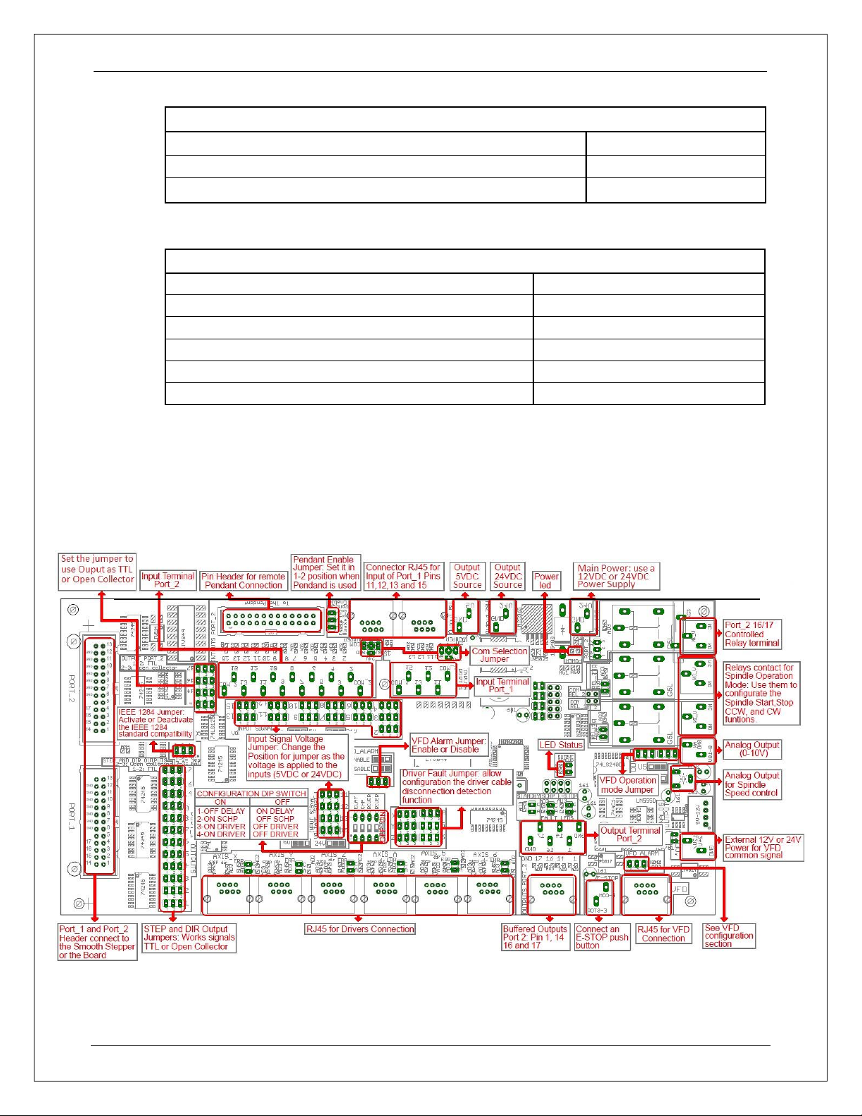
3.0 BOARD DESCRIPTION
User’s Manual
Page 4
4.0 POWER TERMINALS AND CONFIGURATION JUMPERS
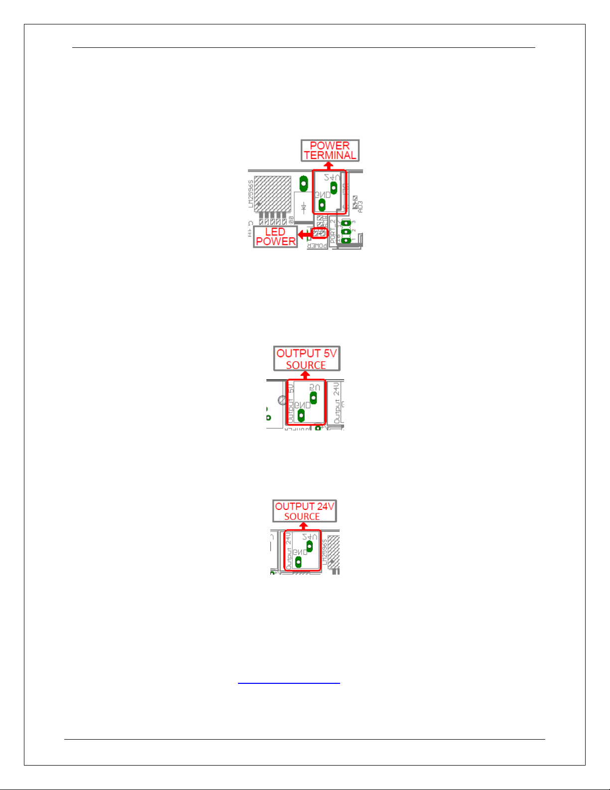
4.1 Power terminal
This input requires an external power 12VDC / 24VDC@1000mA if not using the board to
supply power to external devices.
4.2 Output 5V Source
5V@200mA can be sourced to sensors or other cards requiring it.
4.3 Output 12 / 24V Source
24V@300mA can be sourced to sensors or other cards requiring it.
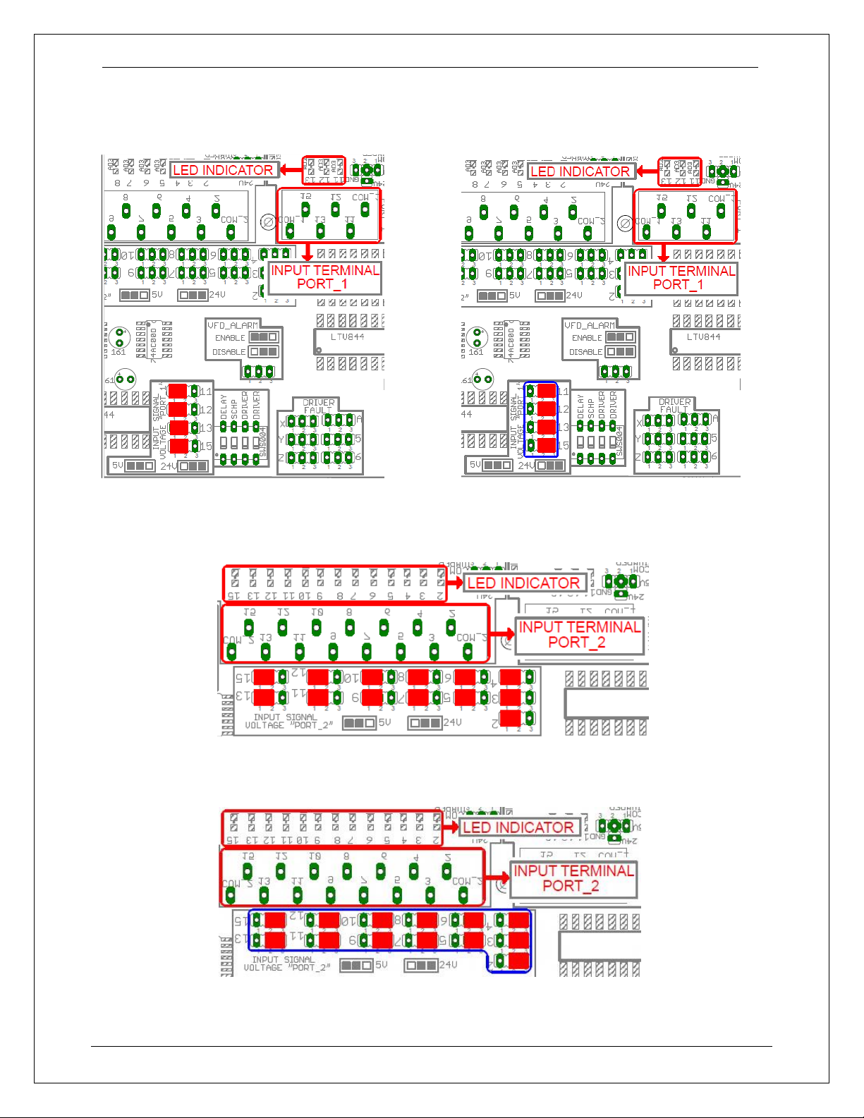
4.4 Input terminals for port_1 and port_2
These terminals support signals 5VDC or 24VDC, you can connect sensors NPN, PNP,
switches, capacitive sensors, etc. set jumpers depending on signal voltage (5VDC or 24VDC).
For see connection diagram go to WIRING DIAGRAMS
User’s Manual
Page 5
PORT_1
INPUT 5V INPUT 12V / 24V
Jumper position changed
PORT_2
INPUT 5V
INPUT 12V / 24V
Jumper position changed
User’s Manual
Page 6
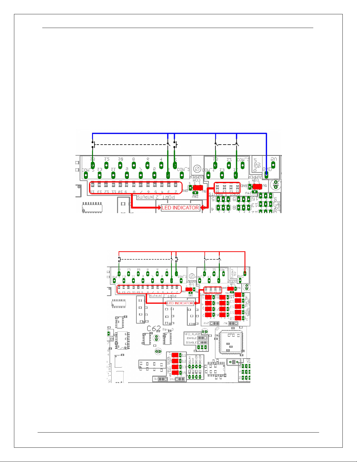
4.5 Select JUMPER COM for the inputs of port_1 and port_2
Set the Jumper to COM = +5VDC, GND or 12VDC / 24VDC to determine the common for the
input signals to be used.
COM = 5V
PORT_2 PORT_1
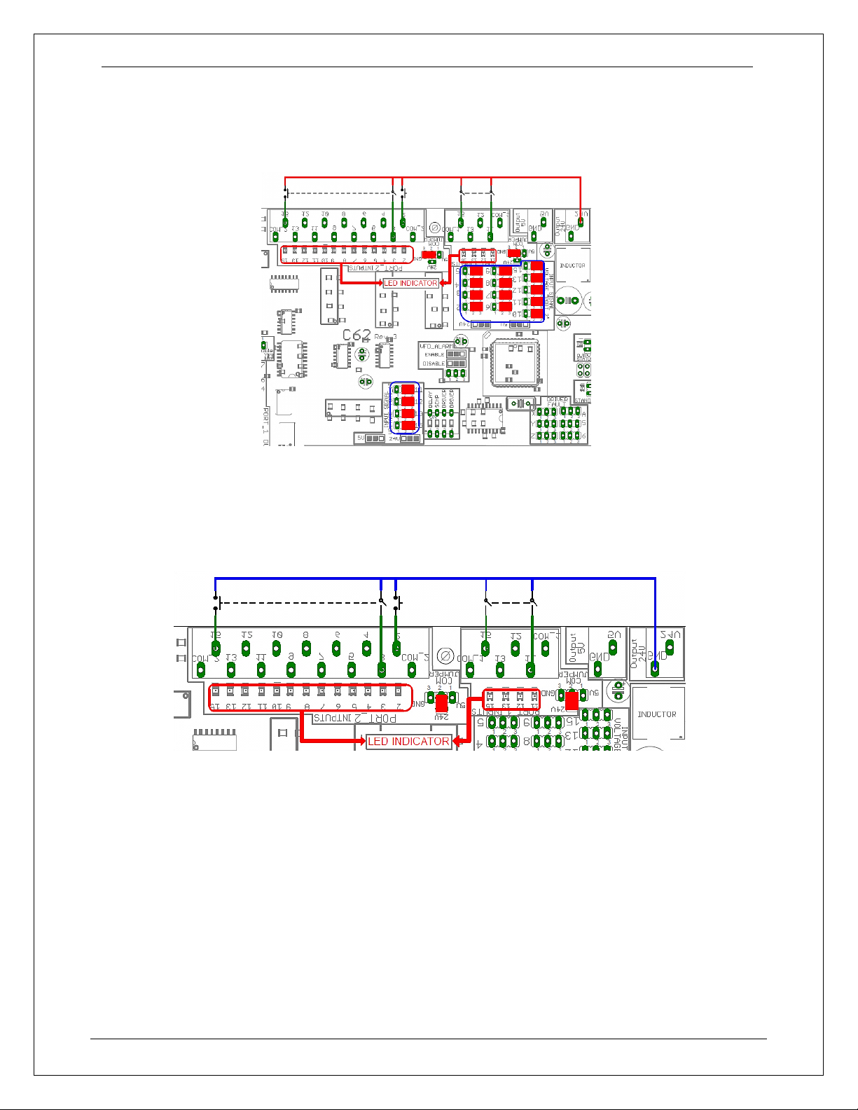
COM = GND with 5V
User’s Manual
Page 7
COM = GND with 12V / 24V
Jumper position changed
COM = 12V / 24V
User’s Manual
Page 8
Isolate Input
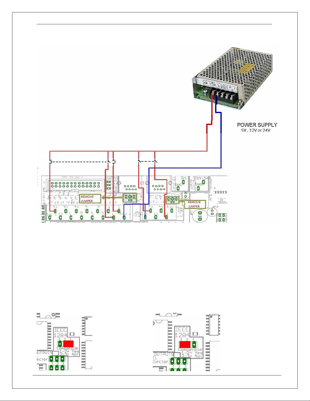
4.6 Controller selection jumpers (IEEE1284/SS)
Some motion controllers are not IEEE1284 compatible, set the jumper select the
compatibility. Set it Non-Compatible if pull-up resistors in the motion controllers activate
outputs when not supposed to.
Compatible (IEEE1284) Not Compatible (IEEE1284)
User’s Manual
Page 9
4.7 TTL or open collector outputs can be used for driver connection.
Use TTL if driver takes +5vdc, or open collector if driver takes +12vdc or +24vdc signals.
TTL
Open Collector
Jumper position changed
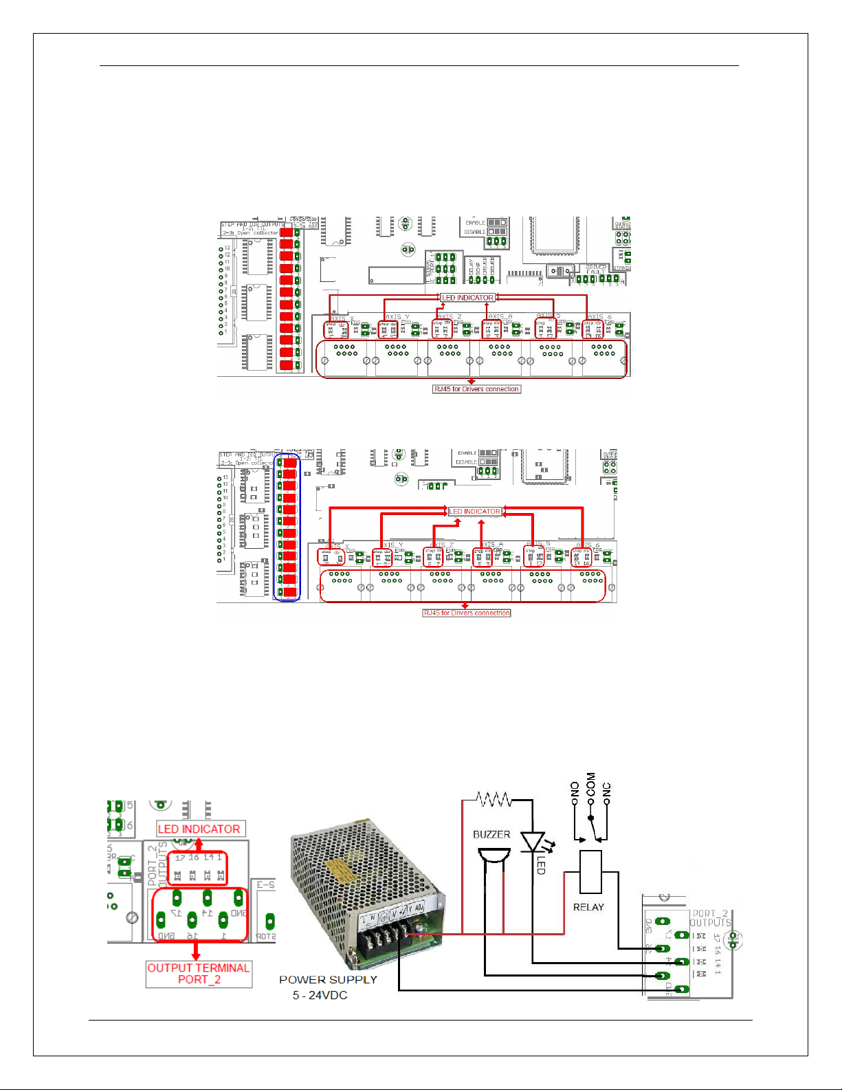
4.8 Output terminal for general purpose
These outputs are open collector
In this terminal, can be connected relay, led or lamps, alarm, etc. this power is external
 Loading...