

Page 1
Page 2

1
Category
Dear Customer:
Thank you very much for purchasing our products! This manual will
provide some important information and recommendations including:
installation, operation and troubleshooting. Before use, please read the
manual carefully and pay special attention to the recommendations
relating to safety.
1. Safety Summary.......................................................................................2
2. Product Introduction................................................................................2
2.1 Introduction....................................................................................................... 2
2.2 Technical Specifications....................................................................................3
3. Operation and Installation....................................................................... 3
3.1 Operation........................................................................................................... 3
3.2 Installation......................................................................................................... 4
4. Precautions...............................................................................................6
5. Applications.............................................................................................7
5.1 Single Application............................................................................................. 7
5.2 Parallel Application........................................................................................... 9
5.3 Series Application............................................................................................10
6. Display and Parameter setting guide..................................................... 11
6.1 Display.............................................................................................................16
6.2 Parameter Setting............................................................................................ 17
6.3 Fault Code....................................................................................................... 23
7. Maintenance & Warranty.......................................................................26
Page 3

2
1.Safety Summary
The following safety precautions should be taken to avoid injury and prevent damage to this
and other associated products. To avoid danger, be sure to use this product in accordance with the
instructions.
Before use, please read the user manual carefully. Operate the equipment according to
instructions.
The power input and output cables should comply with national standards, to avoid
accidental injury caused by inferior cables.
When disconnecting the power input cables, be sure that the power is off first!
When disconnecting the power output cable, be sure that the power is off first!
During operation, do not touch the power input or output cables. This is a shock hazard!
During operation, do not move the inverter!
Inadequate ventilation can cause the machine to overheat and to fail. Do not cover the
ventilation holes! Be sure that the area and inverter have proper ventilation.
Keep the product surface clean and dry. Do not drop small objects inside the machine.
In the event of a temporary power supply cut off, do not open the case to touch the inside
of the device until the capacitors discharge. There is still high voltage inside the machine.
The ground terminal must be grounded (Ground resistance less than 10 Ω ). Use thick
diameter ground cable. Keep the ground cable short and as close to the machine as
possible.Ground is can be parallel.
2.Product Introduction
2.1 Introduction
The Helios Series Inverter consists of a Pure Sine Wave Inverter, MPPT Solar Charge
Controller and an AC Charger. The use of advanced components creates high reliability, high
efficiency, better protection and a cleaner waveform. Here are some other key features:
New soft-start circuit will reduce sparks created during cable connection
Inverter voltage output is programmable
Multiple machines can be wired in parallel for more power
New transfer switch seamlessly switches from grid power to solar power
Three inverters connected in series creates 3-phase power output
Energy metering with various protection functions.
4.3 inch TFT color screen makes operation more intuitive and user-friendly.
The Helios Series Inverter can power instruments, color TVs, satellite receivers, household
appliances, automotive equipment and more. The MPPT Solar Charge Controller can
intelligently control PV modules to efficiently charge the batteries. It is also compatible with
wind power.
Page 4

3
2.2 Technical Specifications
2.2.1 Technical Specifications
Specs
Values
BAT Input Voltage Range (VDC)
24VDC(20VDC-30VDC)/ 48VDC (40VDC-60VDC)
Output Power (W)
2000W/3000W/5000W
AC Output Voltage (VAC)
100V ~250V(Adjustable)
AC Input Voltage (VAC)
100V/110VC/220V/230V
AC Output Frequency (HZ)
50HZ/60HZ(Adjustable)
AC Input Frequency (HZ)
50HZ/60HZ
Pure sine wave Regulation(THD)%
≤3%(Liner Load)
Inverter Efficiency(η)%
≥90%
Over load
110% ≤30S / 150% ≤1S
PV Panel Max Input Voltage(VDC)
150V
PV Panel Min Input Voltage(VDC)
24V(36VDC) / 48V(72VDC)
PV Panel Max Input Power (W)
24V(1800W) / 48V(3600W) – varies by model
MPPT Charging Current (A)
40A/60A – varies by model
Grid Charging Current (A)
15A/25A – varies by model
Dielectric Strength
1500VAC 5mA 1min
Ambient Temperature (℃)
-20℃ to 55℃ (-4°F to 131°F)
Humidity
90% RH Non-condensing
Altitude (m)
≤3000m (≤9800ft)
3.Operation and Installation
3.1 Operation
3.1.1 Open
Before delivery, this equipment has been strictly tested and inspected. To ensure the inverter
was not damaged in transit, please inspect it thoroughly. If any equipment is damaged, contact the
supplier immediately. Make sure the following items are present:
Complete Inverter Body
User’s Manual
Warranty Card
Certificates
Other accessories and components
Page 5

4
3.1.2 Storage
To avoid damage or adverse effects, please store in the following conditions:
clean, dry and well ventilated environment
ambient temperature of -20℃ to 55℃(-4°F to 131°F)
relative humidity of less than 90%, with no condensation
keep away from corrosive or flammable materials
energize every six months, to prevent the internal electrolytic capacitors from drying up
3.1.3 Handling
During the handling process, you should avoid any strong vibrations, bumps or falls. Please
pay attention to safety during handling. Be safe! Do not place the box upside down or sideways.
Keep track of accessories, manuals and warranty cards when taking the equipment out of the box.
3.2 Installation
Please check the box. If there is damage when out of the box or if the box has significant damage,
please contact the supplier immediately.
1) Make sure the front panel power switch is “OFF”
2) In accordance with the terminal block wiring terminals identified
3) "BAT" terminal for the battery
BAT﹢is positive
BAT﹣is negative
4) "PV" terminal for solar panel array
PV﹢is positive
PV﹣is negative
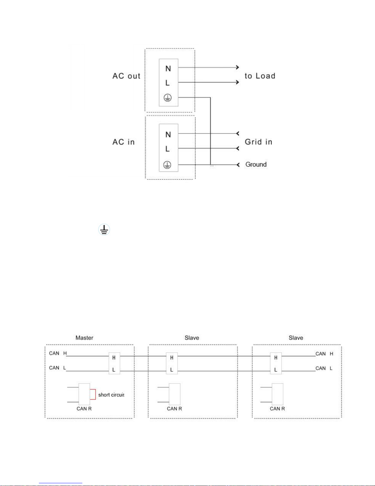
5) "AC OUT"is the output terminal
connect to appliances or circuit breaker panel
6) "AC IN”"is the grid input terminal
connect to grid power
Page 6
5
Note! The Helios Series Inverter has phase lock, but not on the “AC OUT”. Do not connect
the grid to "AC OUT" directly! If the grid is connected to the "AC OUT" directly, the
inverter could be permanently damaged. Due to the inverter being damaged by a
Non-Standard Operation, the warranty will become null and void!
A)
" "
are ground terminals. To be reliably connected together.
B)
"
USB"interface is upgraded with extended functionality.
C)
"
RS485"as the see-through communication (for back-stage applications
when connected to the PC). This is the standard MODBUS communication
protocol. Connect to your computer using the standard communication
module.
D)
"
CAN"port on all-in-one, in parallel or in series, for synchronous
communication. When applied, in parallel or in series, connect together with
CAN"H"and CAN"L". CAN"R"for the CAN load port, must be
connected externally with a cable.
Page 7
6
E)"NC
","C","NO"
for the generator dry node contacts."NC"for the
normally closed contact and"C"for the common contact."NO"is
normally an open contact.
4.Precautions
Do not reverse the battery cables. If reversed, the inverter will not be damaged and
can reboot without any reaction.
Do not reverse the PV inputs. If reversed, it will not damage the MPPT Controller.
The MPPT Controller will have no reaction but charging will not be performed.
When connecting the ”AC OUT”, the total power load should not be more than the
rated power of the inverter. This could permanently damage the inverter. If it is an
inductive or capacitive load, reduce power consumption to avoid exceeding the peak
power of the inverter.
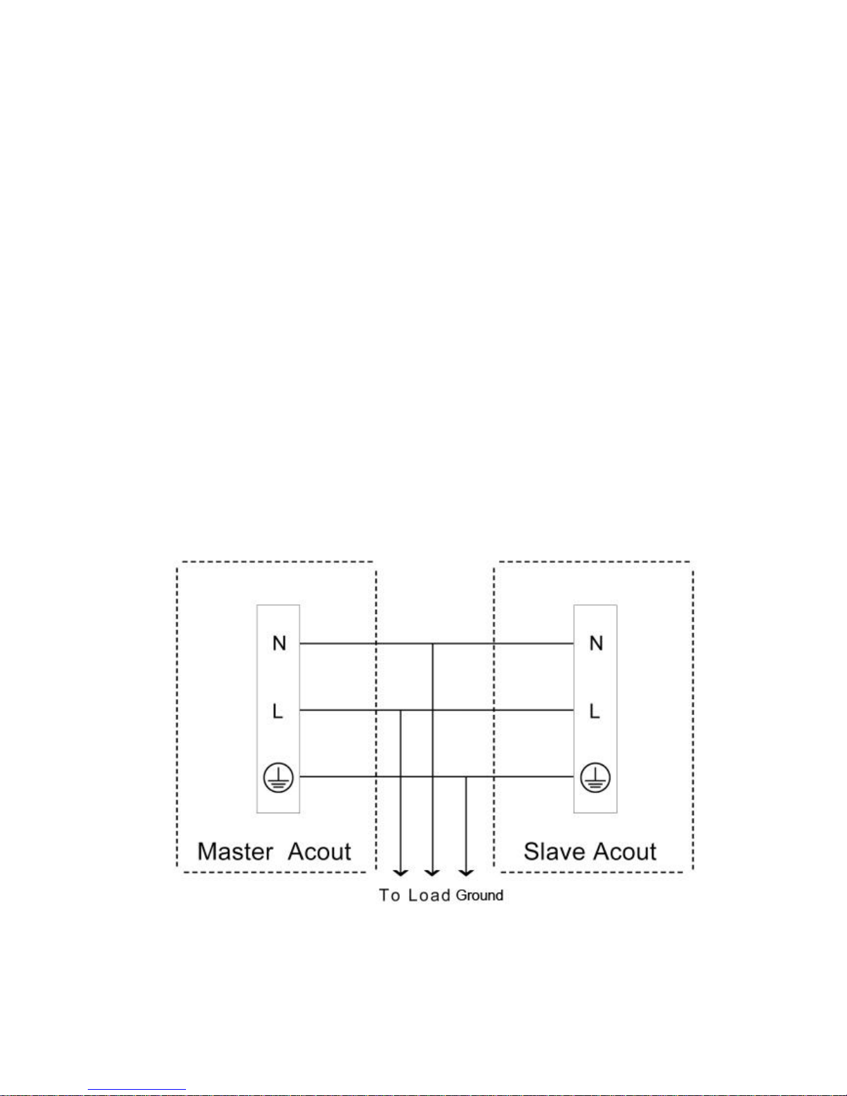
When connecting in parallel, connect the"L"terminal from AC OUT together and
connect"N"terminal from the AC OUT together as well. There must not be a
connection error! Otherwise, it will cause damage to the inverter.
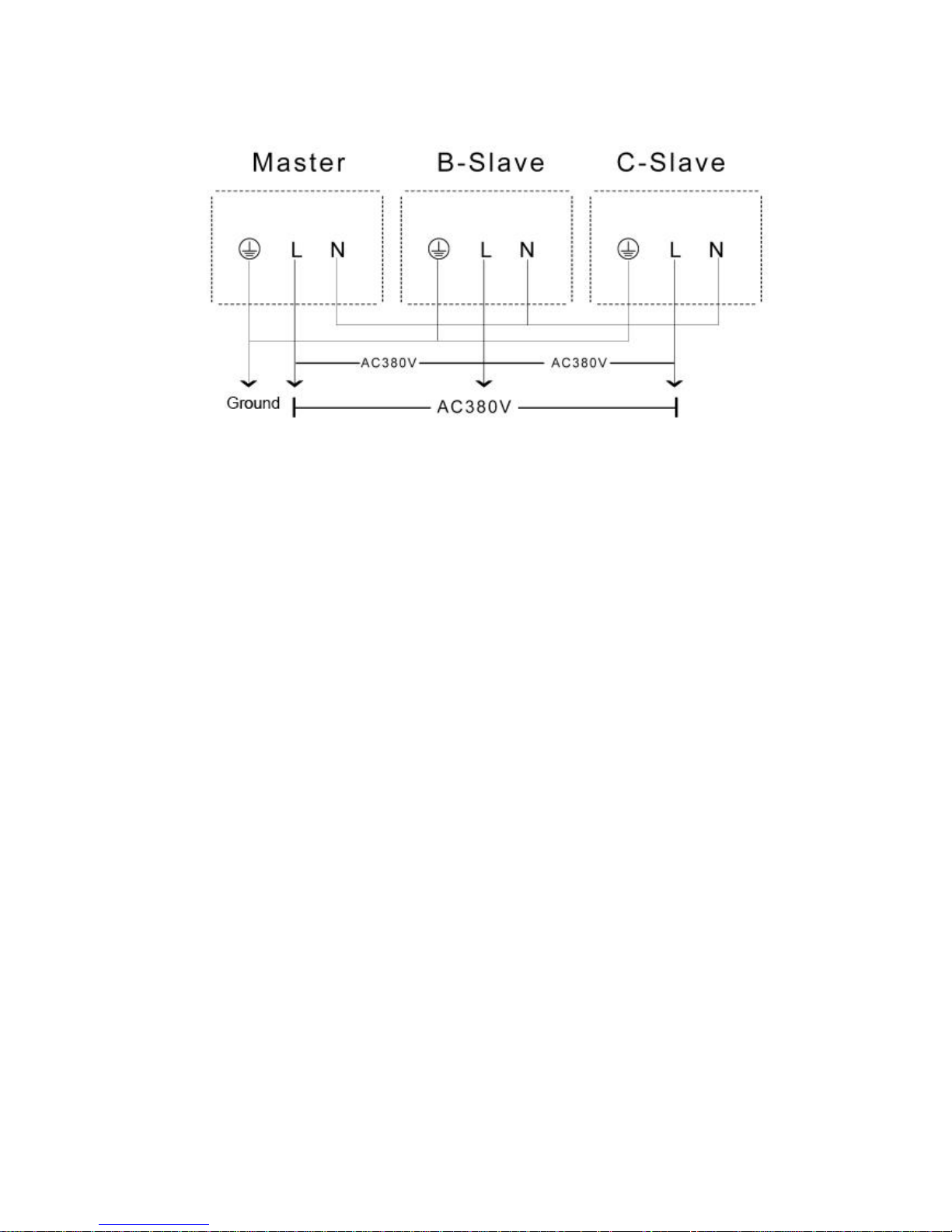
When connecting in series, the 3 inverters need the"N"from the AC OUT to be
connected together. 3pcs"L"constitutes a three-phase output. There must not be a
connection error! Otherwise, it will cause damage to the inverter.
Page 8
7
Connect the AC IN (grid) terminal to a stable grid power supply. If the grid voltage
fluctuates too frequently, or if the grid frequency is unstable, this may lead to phase
lock failure.
USB port is for data communication port only. There is no charging capacity.
When RS485 connect to PC port, needs and supporting the USB to RS485 converter,
cable with standard 8-core.
When the number of inverters in parallel,there must and only a master and one
slave to connect to the “CAN R”.
If would like to connect with PC program,please using the standard USB cable,softw
are and drive can be download from website(www.cnbou.com)
5.Applications
5.1 Single Application
5.1.1 Operating Model
Solar Priority
Under this option, the inverter output is the power supply. When the battery voltage is low, it
will switch to the grid supply or the power will shut off (if the grid is not connected). When the
inverter is providing power and the MPPT Controller is charging the batteries, the AC Charger
will stop charging. If you switch to Grid Priority, the AC Charger and the MPPT Controller can
charge the batteries together.
Page 9
8
"○"running, can be set Manually shut down;"●"operating,"×"Stop.
AC Power Status
Inverter
AC Charger
Module
MPPT Controller
Module
Inverter Output
○×●
Grid Output
×○●
Steps:
1. Make sure the inverter power switch is off! Connect the batteries, PV panels, AC OUT
and AC IN (grid) correctly. Confirm that everything is connected correctly. If you are
using the PC monitoring status, connect the RS485 to your PC before turning the power
on. For cable requirements and definitions, see pages 4 and 5.
2. After everything is connected correctly, press the POWER button to turn on the inverter.
Grid Priority
Under this option, the grid output is the power supply. The inverter output is now the back-up
power supply. The AC Charger and MPPT Controller are now charging the batteries together.
Make sure your batteries are charged sufficiently before a power outage. The AC Charger can be
turned off separately. When the grid is off, it will switch to the inverter power automatically. The
switch time is seamless. When the inverter output starts, the AC Charger will stop charging and
the MPPT Controller will still charge the batteries.
Page 10
9
"○"running, can be set Manually shut down;"●"operating,"×"Stop.
AC Power Status
Function Status
Inverter
AC Charger
Module
MPPT Controller
Module
Inverter Output
×○●
grid Output
○×●
Steps:
1. Make sure the inverter power switch is off! Connect the batteries, PV panels, AC OUT
and AC IN (grid) correctly. Confirm that everything is connected correctly. If you are
using the PC monitoring status, connect the RS485 to your PC before turning the power
on. For cable requirements and definitions, see pages 4 and 5.
2. After everything is connected correctly, press the POWER button to turn on the inverter.
5.2 Parallel Application
The Helios Series Inverter can support up to 30 pcs in parallel with same series to enhance
the power. Internationally standardized CAN communication protocol is used for high-speed
synchronous communication.
Steps:
Note! In parallel, strictly follow the steps and regulatory requirements described below.
If not followed, this may cause the inverter to stop working. In severe cases, the inverter
could be permanently damaged! Due to the inverter being damaged by a Non-Standard
Operation, the warranty will become null and void!
1. For instructions on connecting the inverter’s CAN communication port, wiring
requirements and specifications, see page 5. Note! AC OUT parallel must be after set
Page 11

10
the master and slave. Wiring must be in strict accordance with the specifications!
2. A Parallel Application consists of “Master” and “Slave”. One inverter is “master” and the
rest of the connected inverters are “slave”. After ensuring a correct connection, select one
inverter as “master”, but the master inverter does not need to be set. It is set as master by
default. One by one, turn on the power to the other inverters. Enter the setup mode and set
them to “slave” one by one. Then set the mode to “parallel mode” (see page 22, P 6.2-9).
Note! All slave inverters must be set to the same parameters! Any configuration fault
will be recorded after all the inverters are set up.
3. Make sure all connections are in strict accordance with the requirements on pages 5
and 7. Turn on the master inverter first. Then turn on the other inverters one by one. If
there are no problems with the connection and settings, then begin use. If the inverter
alarm sounds, check to see if the connections, communication cables and settings are
correct. To clear fault codes, see page 18, P 6.2-2.
5.3 Series Application
Helios Series Inverter supports star series communication with three of the same wattage
and input voltage inverters to achieve 3 phase AC output. Suitable for 3 phase motors and other
industrial equipment power supplies.
Steps:
Note! In series connection, strictly follow the steps and regulatory requirements
described below. If not followed, this may cause the inverter to stop working. In severe cases,
the inverter could be permanently damaged! Due to the inverter being damaged by a
Non-Standard Operation, the warranty will become null and void!
1.
Connect all of the three inverter’s CAN communication ports. Then connect the" N "
from the AC OUT together from all three inverters. DO NOT connect the"L"from the
AC OUT! Wiring must be in strict accordance with specifications on page 7!
2.
A Series Application consists of “Master” and “Slave”. One inverter is “Master” and the
rest of the connected inverters are “Slave”. After ensuring a correct connection, select one
inverter as Master, but the Master inverter does not need to be set. It is set as Master by
default. One by one, turn on the power to the other inverters. Enter the setup mode and set
them to “Slave” one by one. Then set the mode to “series mode” (see page 22, P 6.2-9).
Note! All Slave inverters must be set to the same parameters! Any configuration fault
will be recorded after all the inverters are set up.
3.
Restart all inverters, after applying the proper settings, by turning them all off. Make sure
all connections are in strict accordance with the requirements on pages 5 and 7. Turn
on the master inverter first. Then turn on the other inverters one by one. If there are no
problems with the connection and settings, then begin use. If the inverter alarm sounds,
check to see if the connections, communication cables and settings are correct. To clear
fault codes, see page 18, P 6.2-2.
Page 12
11
6.Display and Parameter setting guide
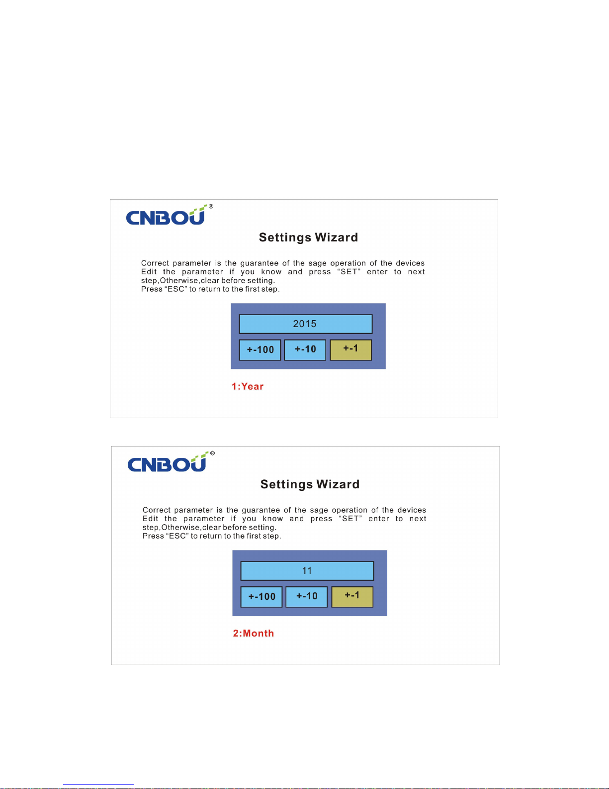
Helios Series Inverter has built-in intelligent and interactive systems. When powering on the
inverter for the first time, it will enter the Settings Wizard. Follow the instructions to set the
parameters and connections. When the settings are finished, the Helios will check the all main
parameters automatically and begin working. All running status and information will begin
recording.
Year
Month
Page 13
12
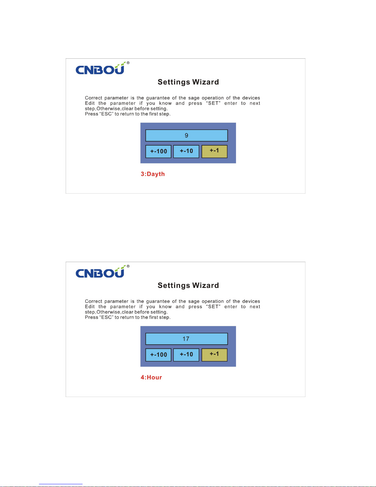
Day
Hour
Page 14
13
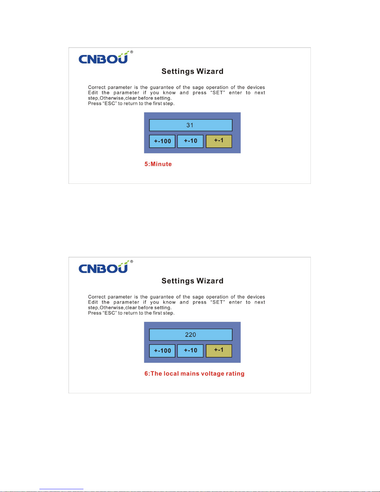
Time: Set the correct time based on your region. The Helios will record the generating capacity
every day as well as the fault code information.
Output voltage: The Helios Series Inverter output voltage can set between 100V-250V to meet
the requirements for each region.
Page 15
14
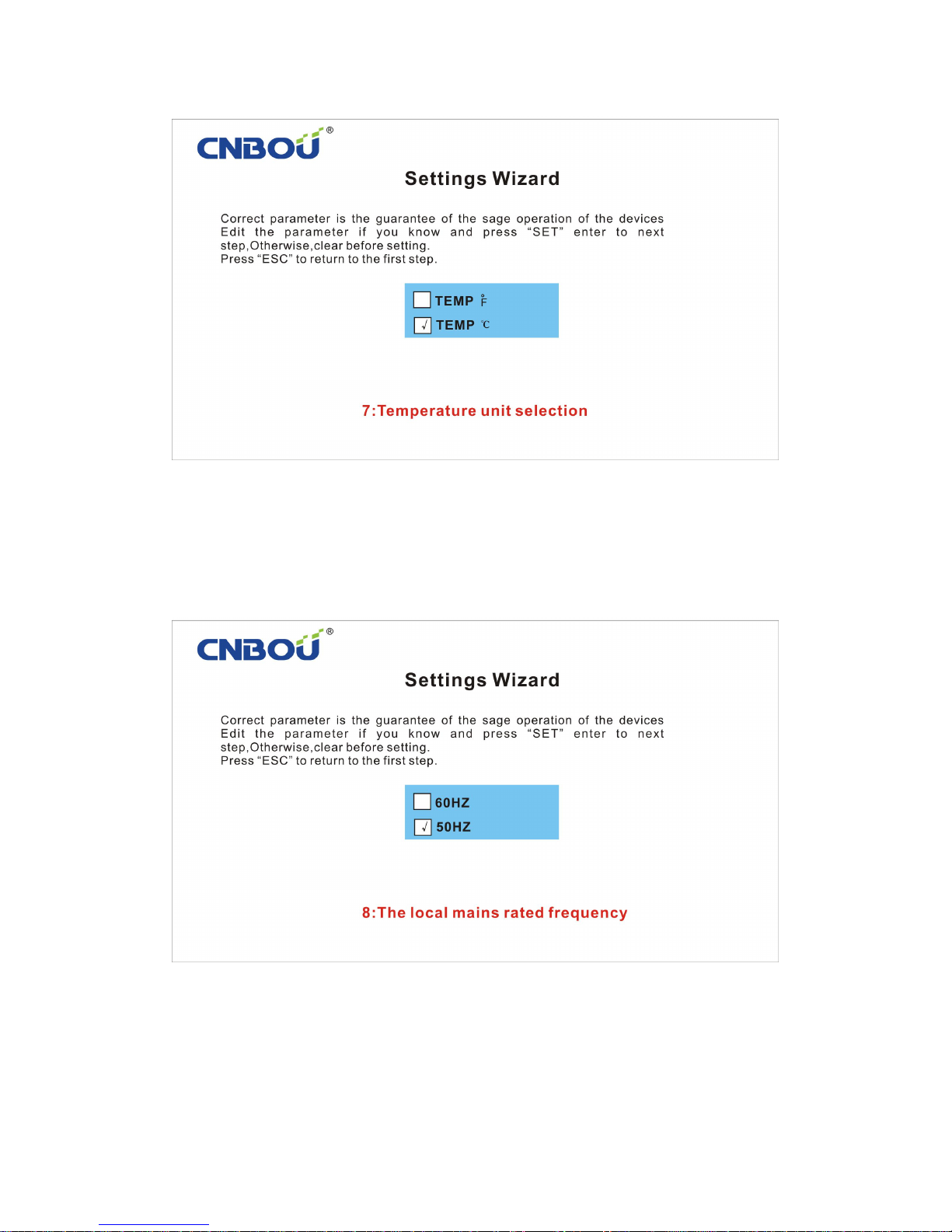
Temperature unit selection: Select Fahrenheit or Celsius.
Grid Frequency: Set it the same as the grid frequency for your region.
Page 16
15
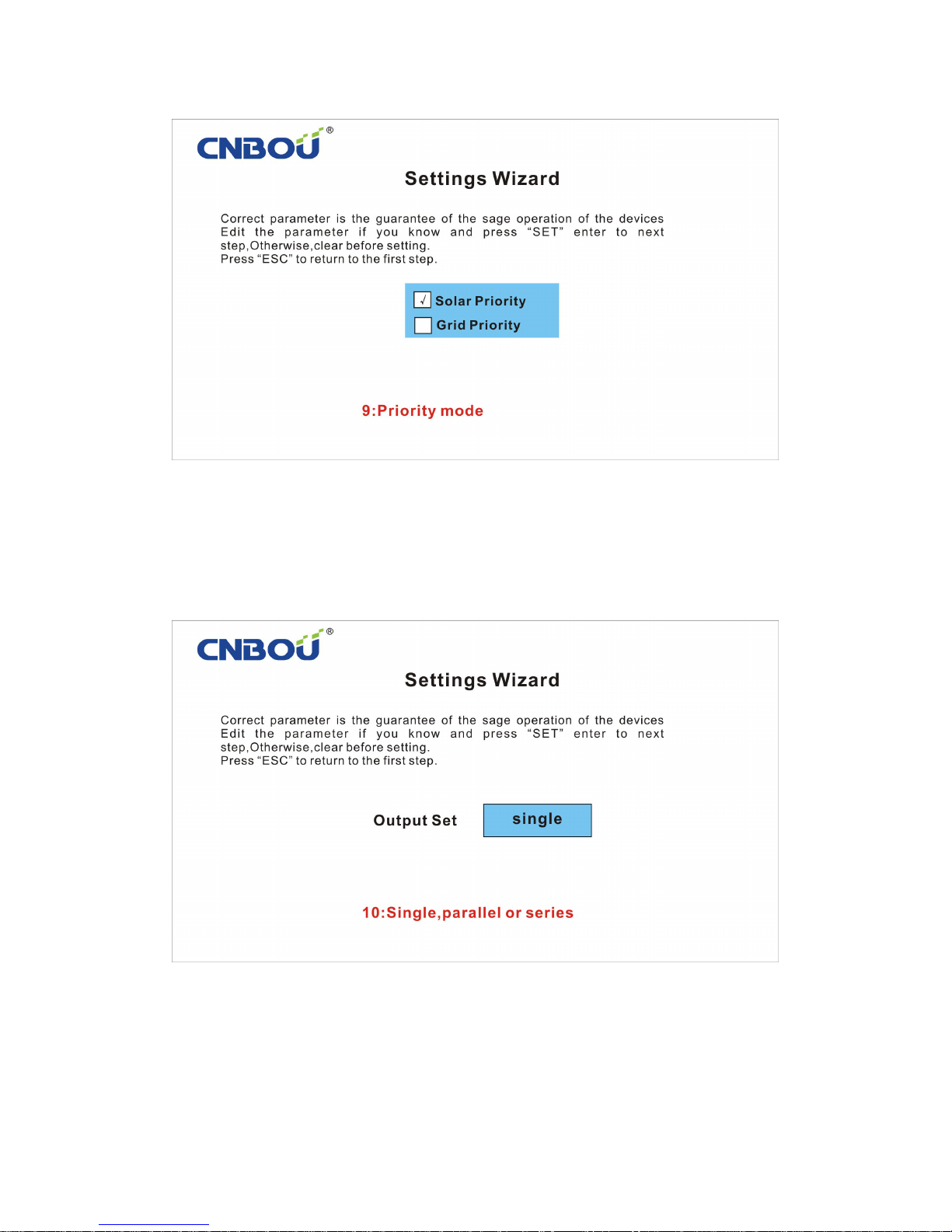
Priority Default: Set Solar Priority or Grid Priority
Output Application: Single, Parallel or 3 phase (Series) Output
Page 17
16
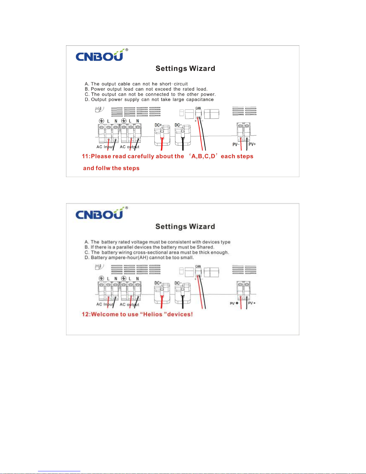
Check all wire connections to ensure that they are correct.
Check the wire connections again and press"SET"to start power.
6.1 Display
Helios Series Inverter uses a 4.3 inch TFT color screen as the monitor display. Now you can
visually monitor the current operating status of the different systems.
Page 18

17
P 6-1
As seen in picture 6-1, you can monitor the battery voltage, PV panel voltage, PV panel
current, MPPT charging current, grid charging current, AC output voltage, AC output current,
output power, inverter and MPPT heat-sink temperature, communication and fault information,
etc.
6.2 Parameter Setting
In the control interface, holding down the " ∧"and "〉"at same time about 5 seconds
will bring you to the settings interface.
P 6.2-1
After entering, click the"∧","∨","〈","〉"arrow keys to move the cursor to the
selection you want to view. Click on the “SET” button to enter the setup. To return to the monitor
interface, press the “ESC” button. Setting interface includes: Main Options, Parameter Setting,
Versions Info, INV Fault Log, MPPT Fault Log, Generating Capacity and Control & Set.
Page 19
18
P 6.2-2
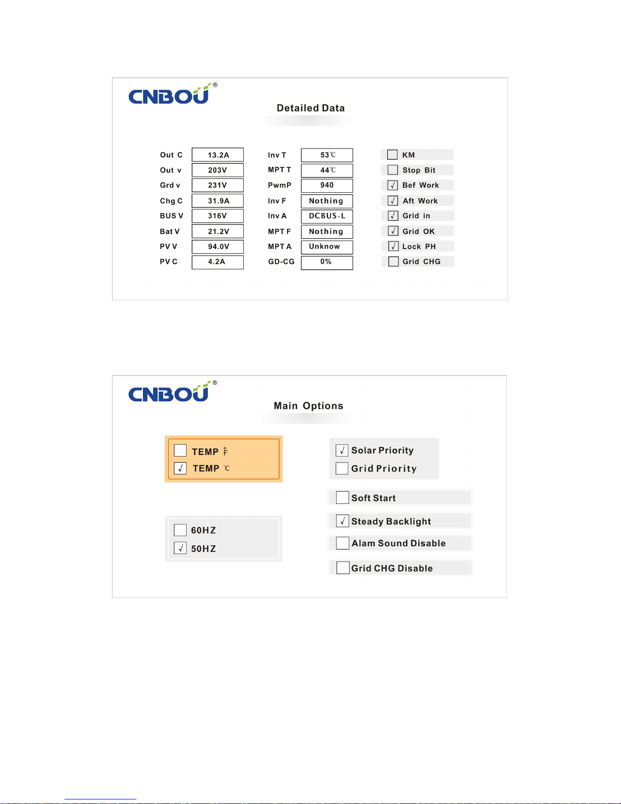
Detailed Data includes: inverter status and fault codes.
P 6.2-3
Main Options includes: Temperature Unit Setting, Grid and Solar Priority setting, Output
Frequency setting, Soft-start setting, Display Steady backlight setting, Alarm Sound setting and
Grid Charging disable setting.
Page 20
19
P 6.2-4
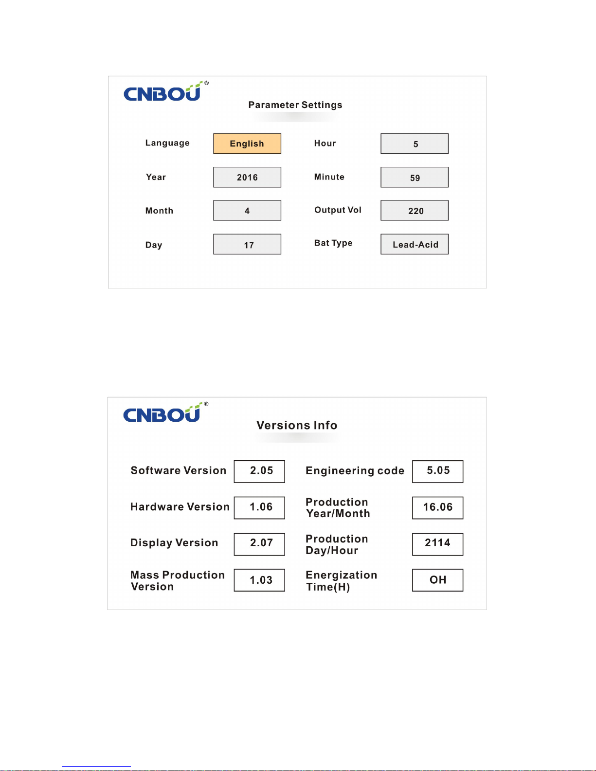
Parameter Setting includes: Language setting, Time setting, Output Voltage setting and Battery
Type setting.
P 6.2-5
Versions Info includes: version No. of software & hardware.
Page 21
20
P 6.2-6
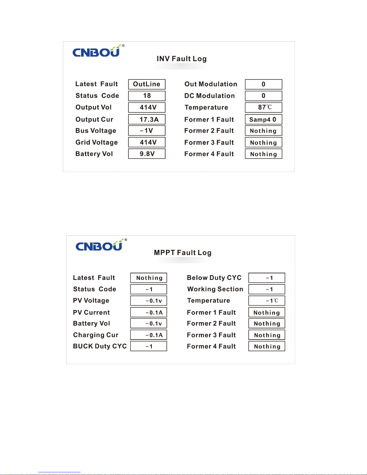
INV Fault Log includes: operating status record of the inverter.
P 6.2-7
MPPT Fault Log includes: operating status record of the MPPT Solar Charge Controller.
Page 22
21
P 6.2-8
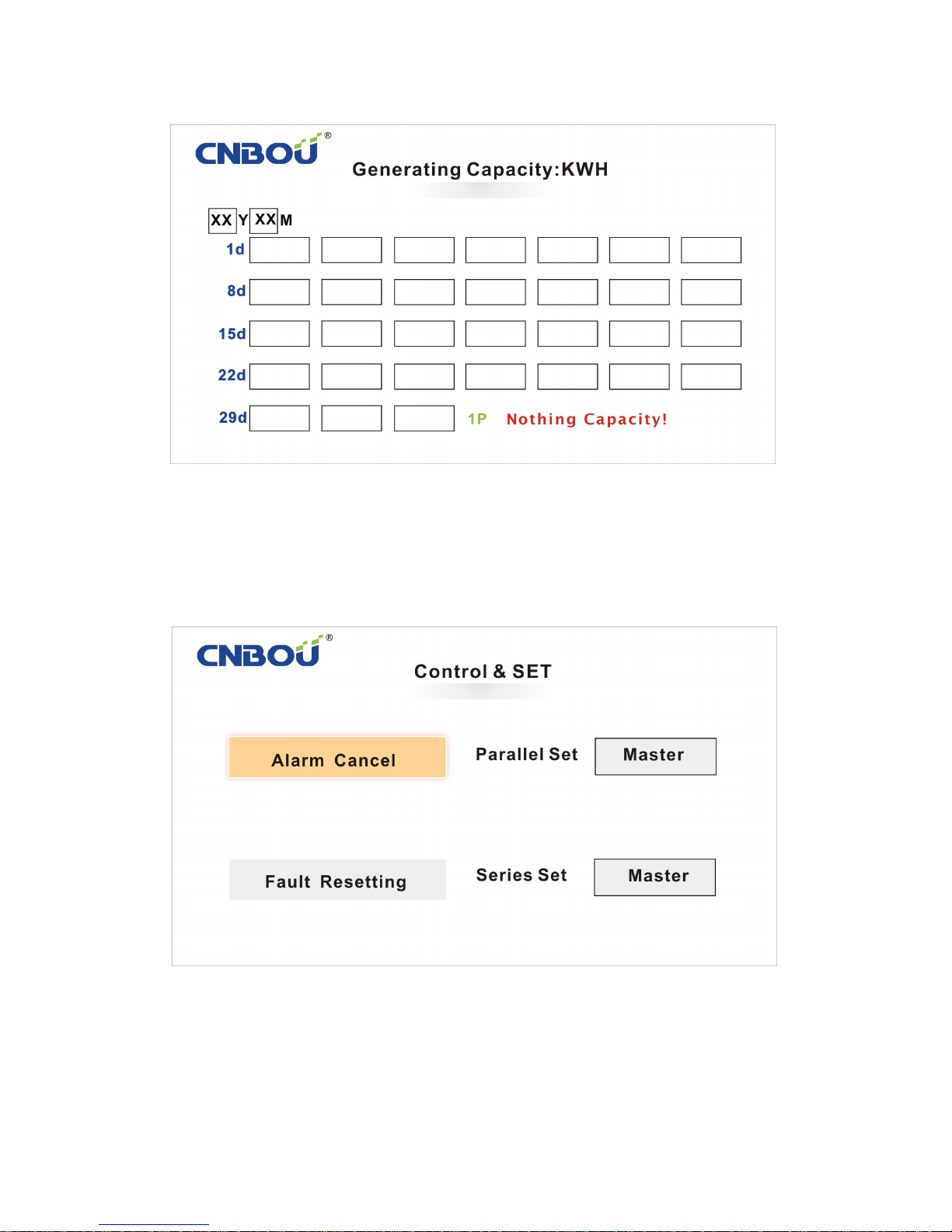
Generating Capacity includes: cumulative record of Generating Capacity. Can be record up to 2
year and then it will clear after a full year.
P 6.2-9
Control & Set includes : Alarm Cancel, Fault Resetting, Parallel Master/Slave settings, 3phase
380V output Master/Slave B/Slave C settings.
Page 23
22
6.2.1 Parallel Master-Slave Setting
In the Parallel Application, only one “Master” is needed. The rest of the inverters are “Slave”.
The Master does not need to be set, only the Slave. Note! Two inverters cannot be set as Master.
All Slave inverters are required to be set. If two inverters are set as Master, it could cause
permanent damage to the inverters!
Move the cursor to Parallel Set “Master”, hold the"∧"choose “Master and Slave”. Set and
save.
6.2.2 Series Master-Slave Setting
In the Series Application, only one “Master” is needed. The rest of the inverters are “Slave”.
The Master does not need to be set, only the Slave. Note! Two inverters cannot be set as Master.
All Slave inverters are required to be set. If two inverters are set as Master, it could cause
permanent damage to the inverters!
Move the cursor to Series Set “Master”, hold the"∧"choose “Master and Slave”. Set and
save. This option includes: “A-Master”, “A-Slave”, “B-Slave” and “C-Slave”. “A-Master” is the
Master inverter. The “B-Slave” is the first Slave inverter.
In the series application, please note the phase sequence! When in Series Application, the
Slave “Series Set” option must set to “B-Slave” and “C-Slave”, they cannot be set to the
same Slave. For clarification, see table on page 23.
After setting the master and slave, ensure that your settings and connections are correct to
prevent any errors or failure caused by incorrect operation. If you receive a configuration error
after you have finished the parallel master and slave settings, turn the power off and check your
connections and settings. Then restart the inverter.
Master/Slave
Parameter
Main Options
Parallel Setting
Series Setting
Master
Master
Master
A-Master
Slave 1
Slave
Slave
B-Slave
Slave 2
Slave
Slave
C-Slave
Parallel and 380V 3phase connection application parameter setting table
Page 24

23
6.3 Fault Code
6.3.1 Short-C Meaning: Short-circuit
Reason: Boost switch tube or output IGBT drive circuit short circuit protection
Solution: 1.Remove the short circuit line's source.
2.The load has a large capacitor, remove.
3.The output error of active devices, remove;
6.3.2 Over-C Meaning: Over-current
Reason: When the load current is more than 1.5 times,the time longer than 1 second
Solution: 1. If the average load is too large ,reduce the same time run the device, or change a
higher power model.
2. If the output is connected to a equipment with large started transient current ,closing
the other equipment when start it, or change a larger power model.
6.3.3 Over-L Meaning: Over-load
Reason: When the load is bigger than the rated power cumulative running time is long
Solution: 1.If the average load is too large, it needs to reduce the same time running machine,
or change a higher power model
6.3.4 Over AC Meaning: Grid over voltge
Reason: The input of the grid voltage exceeds the device setting range
Solution: 1.The device rated-voltage is not right,reset.2:Input grid regulation difference, exceeding
the standard, input installation of the regulator
6.3.5 Over-H Meaning: Module radiator temperature is too high
Reason: The input of the grid voltage exceeds the device setting range
Solution: 1. The environment temperature is too high, move the device to the low temperature,
cool and ventilated place;
2. The surface of the device, the internal dust too much, to clean up the dust;
3. Fan failure, replace the fan
6.3.6 Bat Low Meaning: Battery Low voltage
Reason: Low battery
Solution: 1. Charging for the battery, or to meet the conditions of the device to charging the
battery,when the solar priority the fault is normal, as long as there is solar and battery
charging the battery will automatically reset the fault.
Page 25

24
6.3.7 Bat Hi Meaning: Battery over voltage
Reason: Battery voltage is too high
Solution: 1. When there is a sudden disconnect the battery connection action, the action is very
dangerous, check the battery wiring is reliable.
2. The battery capacity is too small, the charging current relative to the battery is too
high, increase the battery capacity.
3. The battery is damaged, replace the battery.
6.3.8 SYN Acc Meaning: Synchronous fault
Reason: Grid input phase not SYN with device
Solution: 1. The frequency accuracy of the GRID power supply is poor,do not connect the own
power supply to the device grid input,and the device can not be used to load at the
same time.
2. The grid input excessive ripple interference,installation of input filter.
3.Grid input terminals of the device should not connect the offline without phase lock
power, such as: dual power switch or unlock phase UPS, otherwise phase will
dangerous mutations caused by a short circuit
6.3.9 DCBUS-H Meaning: DC Bus over voltage
Reason: Bus voltage is too high
Solution: 1. There is a surge voltage input, if the power supply have quality problems, please add
the input surge absorption equipment and filtering device.
2. Output error of active devices, remove suspected load.
3. Output soft short circuit or grounding, check the output circuit.
6.3.10 EEP ROM Meaning: Storage fault
Reason: Interior storage break down
Solution: Interior fault
6.3.11 Samp-? Meaning: ADC testing fault
Reason: ADC detection circuit internal fault ("?" can be "1" to "4" arbitrary value)
Solution: Interior fault
6.3.12 CAN M-E Meaning: CAN communication conflict
Reason: Series parallel device detected more than two units of the master
Solution: 1. The series parallel network can only have one master
Page 26

25
6.3.13 CAN O-T Meaning: CAN communication over time
Reason: CAN slave detect the communication interrupt timeout
Solution: 1. CAN communication wire is not reliable,exclusion it;
2. CAN network must have an 120Ω anti reflection resistance, every device has an
120Ω resistance, but the entire network can only have one device short connect to
this resistance,proposed short connect with the farest one from master.
3. The interference too much, CAN communication wire was recommended to use a
dual core shielded wire connection, shielding layer grounding, the worst also want to
use a twisted pair connection.
6.3.14 H-W LCK Meaning: Hardware lock up
Reason: Drive circuit fault
Solution: Interior fault
6.3.15 OutLine Meaning: Outline with eletric
Reason: The output wire is connected to the power supply.
Solution: 1. The output wire was connected to the device with AC power output,remove it.
2. The failure is only produced by the power of the detection, once the output is normal
will no longer be detected, can not be expected to be used to protect when the device
is working.
6.3.16 CHGR -C Meaning: Solar charging over-current-1
Reason: Solar charging,battery current over current
Solution: PV panel configuration too large, reduce the configuration
6.3.17 PV -OC Meaning: Solar charging over-current-2
Reason: Solar charging,PV panel current over current
Solution: PV panel configuration too large, reduce the configuration
6.3.18 PV -OV Meaning: Solar panel over voltage
Reason: Solar panel voltage over voltage
Solution: Series PV panel too much, reduce it
6.3.19 BT Full Meaning: Battery full charging
Reason: The battery is full, the fault is only a notice, will automatically reset
Solution:
6.3.20 Unknow Meaning: Unknow
Reason: Extension,not defined
Solution:
Page 27

26
7. Maintenance & Warranty
The Helios Series Solar Inverter has a 2 year warranty. The warranty period begins from the
date of sale.
7.1 Device Maintenance
In order to maintain the best long-term performance, we recommend checking the following
twice per year:
Confirm the inverter is securely mounted in a clean, dry environment.
Confirm that the airflow around the inverter is not blocked. Remove any dirt or debris
from the heat sink.
Check all exposed wire. Check for wire insulation damage as a result of the sun, friction
from other objects, dry rot, insect or rodent damage, etc. If necessary, repair or replace the
wires.
Tighten all electrical terminal fasteners as recommended.
Check all parts of the system ground to verify all ground wires are securely and properly
grounded.
Check all the terminals. See if there is any corrosion, insulation damage, high temperature
or signs of burning/discoloration. Tighten terminal screws to the recommended torque.
Check if there is dirt, nesting insects or corrosion. Clean up as required.
If the arrester has failed, replace the failed arrester in a timely manner to prevent the
controller or other devices from being damaged by lightning.
7.2 Repairing Procedure
Before calling a repair center, read the user’s manual to troubleshoot the possible problem. If
you cannot solve the problem, send back to the company, freight prepaid, and provide the date and
place of purchase. In order to enjoy the rapid repair warranty service, returned products must
indicate the model, serial No. and noted failures. Please provide information on all of the system
components, types, related parameters, battery and system load conditions. This information is
essential for the rapid diagnosis and repair of your Helios Series Inverter.
If the Helios Series Inverter is damaged due to improper use or failure to follow proper
procedures, the supplier is not responsible for replacement or repair!
Page 28
27
 Loading...