

Page 1

Rev 1.1
Network Camera
(“M” Series)
User Manual
Page 2
2
Network Camera_ User manual
Revision History:
Date Rev No Description
Dec. 1th, 2013 1.0 Creation of the Document
Feb. 20th, 2014 1.1 Modified “2.7. Video Setup - ISP Module Adjust”
Indications:
Warning : Death or Serious Injury will occur without following Warning.
Caution : Operational Problem(Faulty & Malfunction) will occur without complying with Caution.
Reference : Technical Information for Users.
Page 3

3
Network Camera_ User manual
Contents
1. PREPARATION FOR THE CONNECTION ................................................................................... 4
1.1. Product Installation .............................................................................................................. 4
1.2. PC Requirements .................................................................................................................. 6
2. CONFIGURATION IN ADMIN MODE ......................................................................................... 7
2.1. Access ................................................................................................................................. 7
2.2. Layout of the admin mode .................................................................................................... 9
2.3. Basic Setup ........................................................................................................................ 10
2.4. Network Setup ................................................................................................................... 12
2.5. 802.1x Setup ..................................................................................................................... 14
2.6. Onvif Setup ........................................................................................................................ 15
2.7. Video Setup ....................................................................................................................... 16
2.8. User Admin & Time Setup ................................................................................................... 18
2.9. Sensor & Capture Setup ..................................................................................................... 20
2.10. E-Mail & FTP Setup ............................................................................................................ 22
2.11. Alarm Device Setup ............................................................................................................ 23
2.12. Motion Detection Setup ...................................................................................................... 24
2.13. Audio Detection ................................................................................................................. 26
2.14. PTZ Setup .......................................................................................................................... 27
2.15. Upgrade & Reset ................................................................................................................ 28
2.16. Status Report ..................................................................................................................... 31
3. WEB VIEWER ......................................................................................................................... 32
3.1. Web Viewer ....................................................................................................................... 32
3.2. Buttons and Indicators of Web Viewer. ................................................................................ 33
3.3. Crop Video Setting ............................................................................................................. 34
3.4. PTZ Control Menu .............................................................................................................. 35
4. TROUBLE SHOOTING AND TIPS ............................................................................................ 39
4.1. Trouble shooting after installation ........................................................................................ 39
4.2. Trouble shooting after successful connection to the device.................................................... 40
Page 4

4
Network Camera_ User manual
1. Preparation for the connection
1.1. Product Installation
Brief information for rapid installation is provided in this section. For more detailed information you are
recommended to refer to pertinent documentations provided with the product.
1. Apply Power to the product and connect the product with network cable.
Applying improper power to device can cause damage to the device.
Varieties of power supplying option are provided for each of the product. Please refer
to the manual of each specific product for available option.
2. Install “IP installer (Ver.3.0.1 or above)” and “NVR-Pro (Ver.5.17 or above)” on your PC.
Each Program is included in the CD coming with product and can be downloaded from
www.cnbtec.com.
Detailed information for installing these programs can be found in [IP-Installer User’s Guide] and
[NVR-Pro User’s Guide], respectively.
3. Assign IP address to the product using IP installer IP Installer.
Identify the type of the network environment and set up IP address. Detailed process of setting up
IP address can be found in [IP-Installer User’s Guide]. If network type is xDSL or Cable modem
you need supplementary information provided by your ISP.
Page 5
5
Network Camera_ User manual
< Quick Installation Guide of IP-Installer >
Install the IP Installer on the PC or Laptop. The WinPCap installed together is required software for the
operation of IP-Installer. Please install the WinPCap essentially as when it is not installed, IP Installer won’t
operate.
a. Starting IP-Installer.
Upon initiation of the IP-Installer, the PC will ask for the selection of proper network adaptor. Click on
proper LAN or WIFI network interface module displayed to highlight the selection and click on “OK”
to start the program.
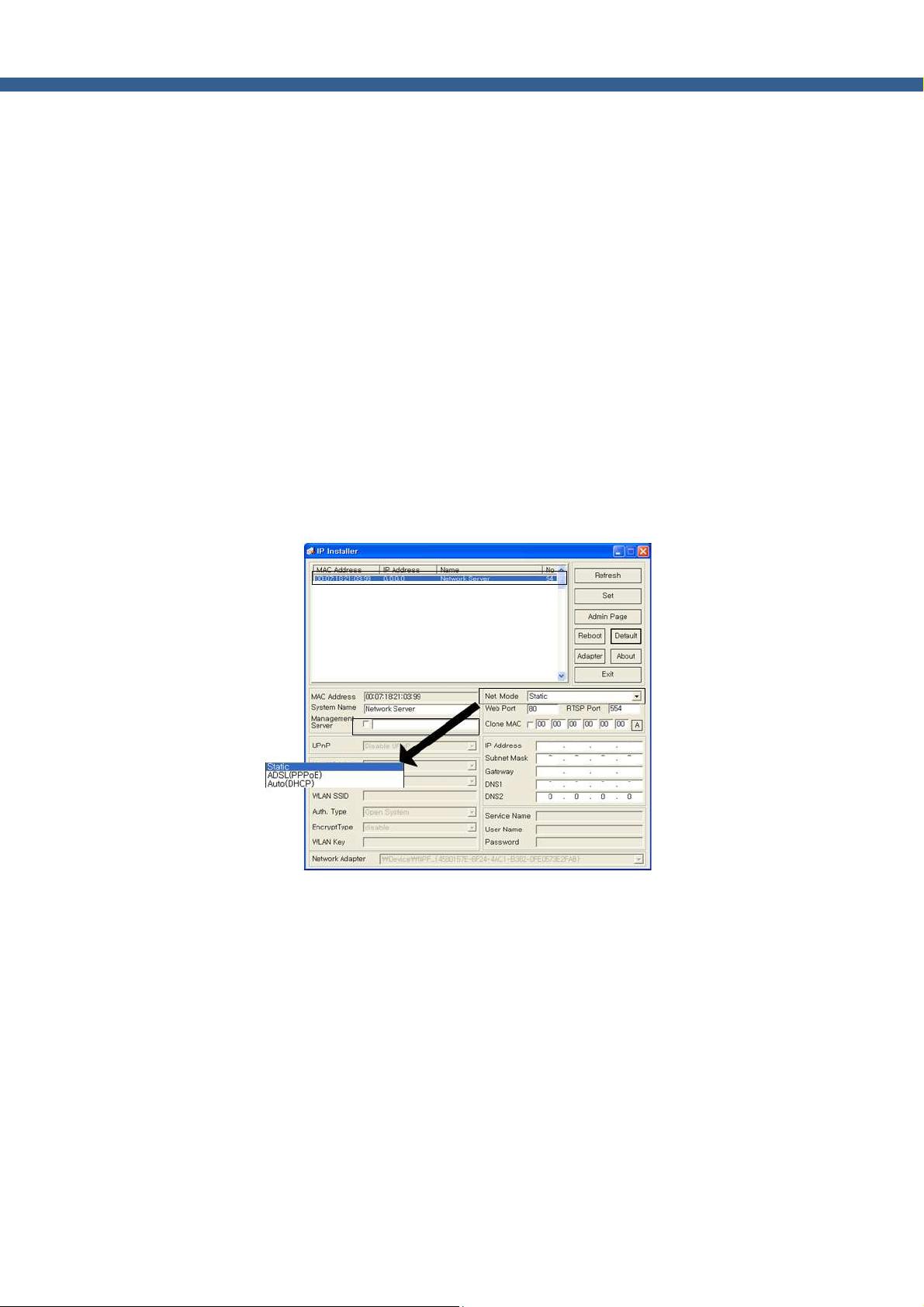
b. Find the product for the configuration
Click on “Refresh” button to find the list of the products (IP cameras or video servers) connected on
the same subnet as the PC.
]
Fig. 1-1. IP-Installer Product Search
c. Assign network parameters needed for connection to the product. Please follow through
the following procedures.
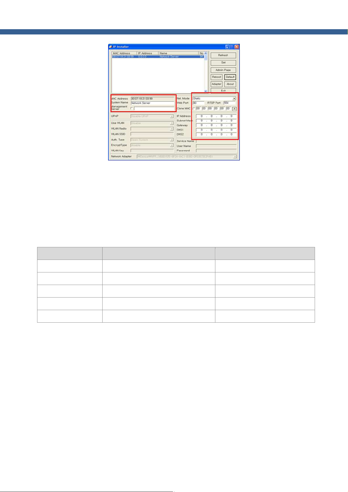
i. Double click on a product you want to set up.
ii. Once the parameter Fields as shown Fig 1-2 are activated, set the network parameters.
iii. Once you fill in the fields, click on “Set” to initialize the product with new settings.
Page 6
6
Network Camera_ User manual
Fig. 1-2. IP-Installer Parameter Setting Up
1.2. PC Requirements
AV streaming data received from IP camera or video server can be decoded or stored in a PC running
NVR-PRO program or other CMS program. Minimum requirement of the PC is recommended as in the
following table.
Item Minimum Requirements Misc
CPU Intel Core i3 above
RAM 2GB
Graphic Card ATI Chip Set Based, 512M above Resolution : 1920x1080 above
LAN Card 100Mbps above
OS Windows XP / Windows 7
Page 7
7
Network Camera_ User manual
2. Configuration in Admin Mode
The detailed operational parameters of the product can be configured through Admin Mode via network.
2.1. Access
The access to Admin Mode can be done using 2 ways; through Internet Explorer and the “NVR-Pro”
program.
1. Using Internet Explorer
Type in the connection address of the product in the address field of the Internet Explorer as
followings:
http://[IP address of the product]/admin.htm
Example : http://172.16.64.133/admin.htm
If you changed the HTTP port of the product from default value (80) you can access to Admin mode
by adding HTTP port address as the following:
http://[device IP address]:[HTTP port]/admin.htm
Example : http://172.16.64.133:8080/admin.htm
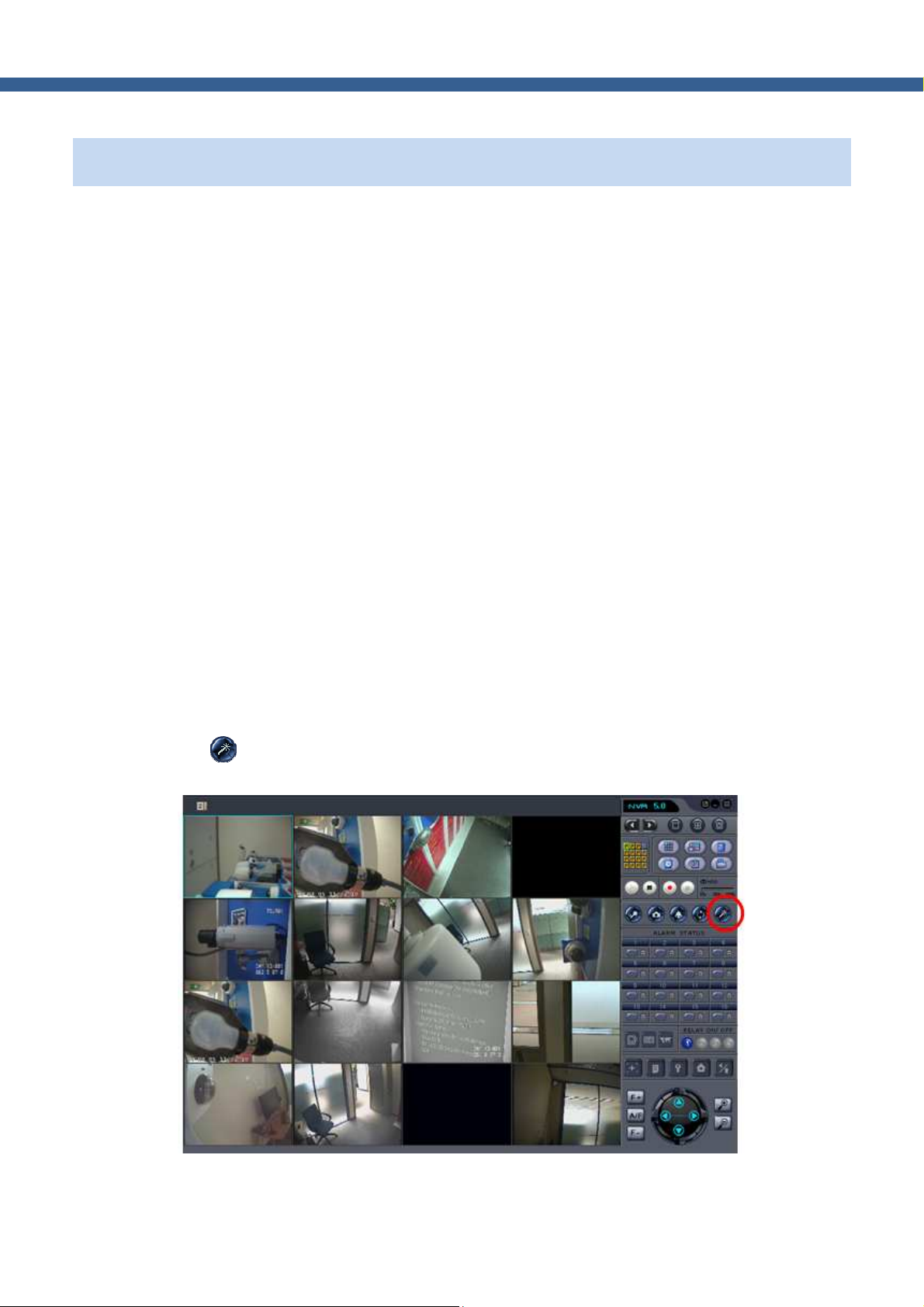
2. Using the “NVR-Pro”
Select video channel in the viewing window of “NVR-Pro”. Selected video channel will be highlighted,
then Click button on the right side of the display screen to access to admin mode.
Figure 2-1. Access to admin Mode from “NVR-Pro”
Page 8
8
Network Camera_ User manual
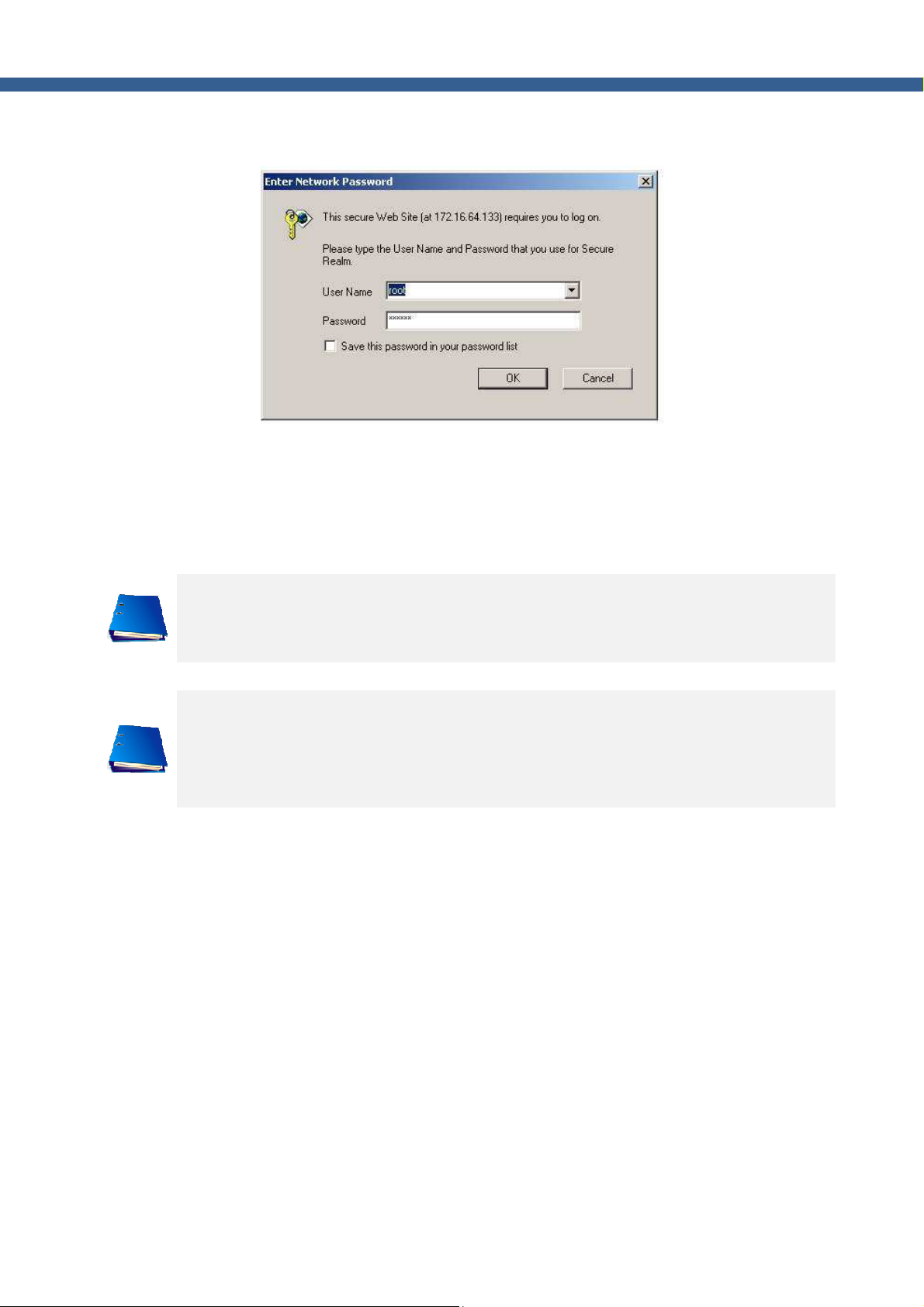
3. Input User Name and Password in the display screen shown below.
Factory default “User Name” and “Password” are set as “root” and “admin”, respectively. Click on
“OK” button to enter into the Basic Setup page of Admin mode. If you have changed the username
and password of the Administrator, you must log on with the changed username and password.
For the sake of enhanced security, we strongly recommend you to change ID and Password
during the installation and keep the ID and Password carefully for not opening to others.
The details are described on [User Admin & Time Setup] section of this document.
If ID and Password are lost, restore the factory default value by following the procedure
below.
When the power is applied to product, press the Factory Default button for more than 3 sec,
then all Setting Parameters will be returned to Factory Default.
Page 9
9
Network Camera_ User manual
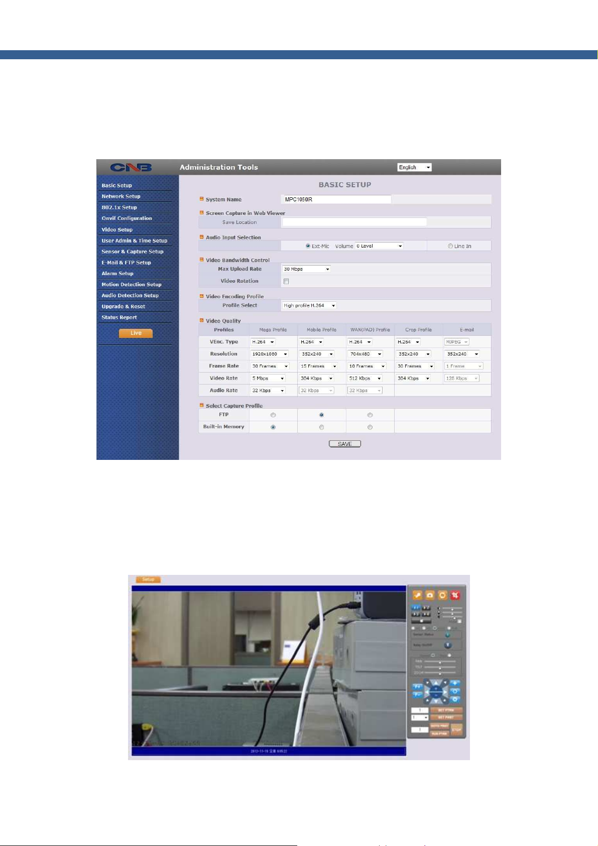
2.2. Layout of the admin mode
Upon initiation of the admin mode, the screen similar to the following picture will be shown.
The left side of the admin page shows various admin Mode menus, while the right side shows the settings
of selected admin menu. Click each of the menu items at the left to go into specific admin mode.
Fig. 2-2. Layout of Admin Mode
Select the language of your preference from drop down list at Top-right.
Click on “Live” button for initiating live video connection after finishing Admin Mode.
The following sections describe details for each admin mode menu.
Page 10
10
Network Camera_ User manual
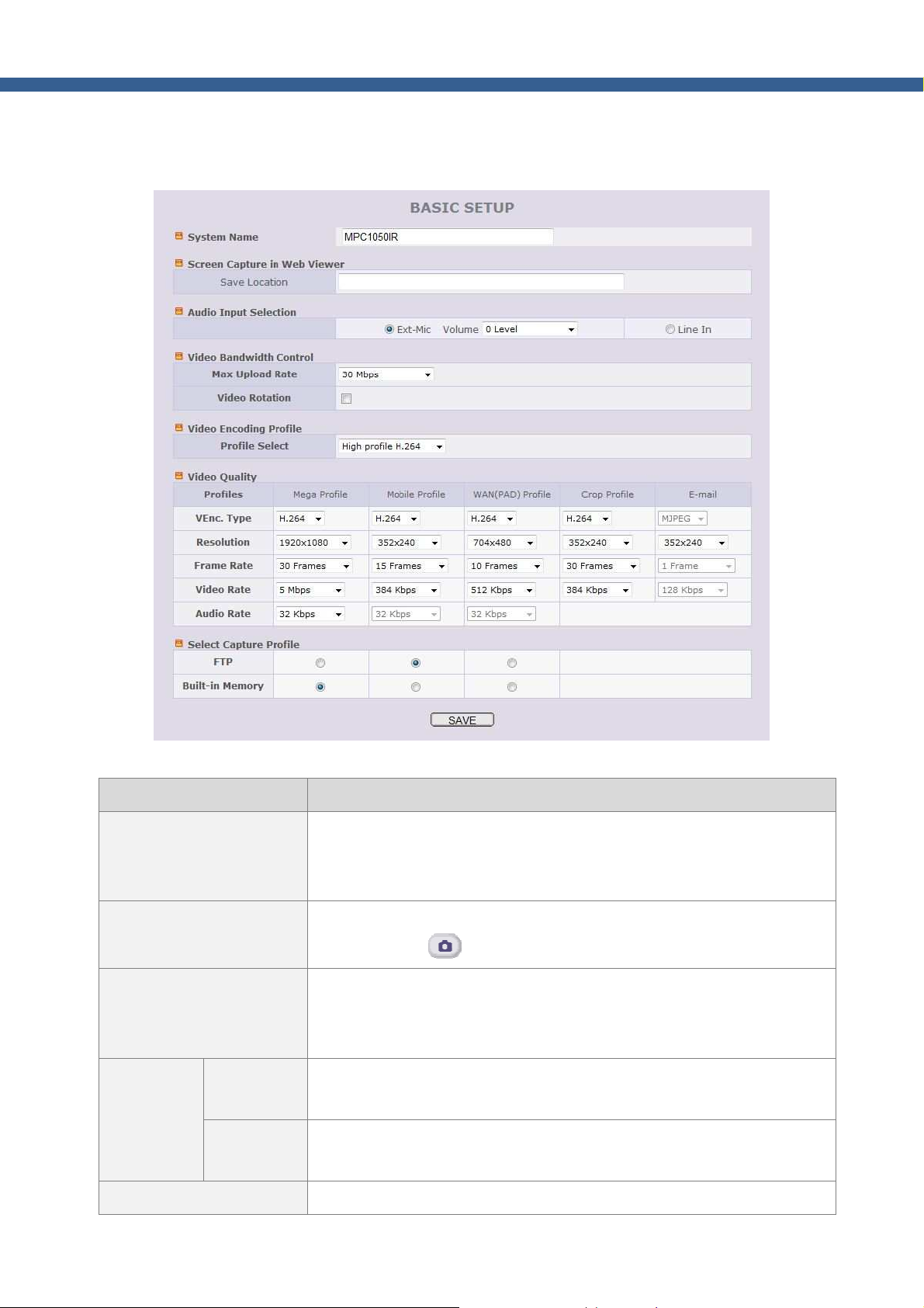
2.3. Basic Setup
Setup the basic parameters for the operation of the product.
Item Description
System Name
Screen Capture in Web
Viewer
Audio Input Selection
Max upload
Video
Bandwidth
Control
rate
Video
rotation
Fig. 2-3. Basic Setup
Logical name of the product. It is same as the one set-up by IP-installer.
You can reassign the logical name. The system name will be shown in the
connection through NVR-Pro.
Designate the folder to save captured image in Web viewer by clicking
capture button ( ). Default path is Desktop.
Select the type of input audio.
Line In : used for Line-out from general audio device.
Ext-Mic : used for Microphone
Assign maximum bandwidth of the uplink for the network connected to
device.
Check at the box to rotate the video by 180o.
Video Encoding Profile Select video encoding profile.
Page 11
11
Network Camera_ User manual
Baseline : Primarily for low-cost applications like as videoconferencing and
mobile applications.
Main : Used for standard-definition digital TV broadcasts.
High : primary profile for broadcast and disc storage applications,
particularly for high-definition television applications (for example, Blu-ray
and the DVB HDTV)
Select profile for your circumstance. Default is “High profile”. Check
whether client supports selected profile because video can't be displayed
if client does not support selected profile.
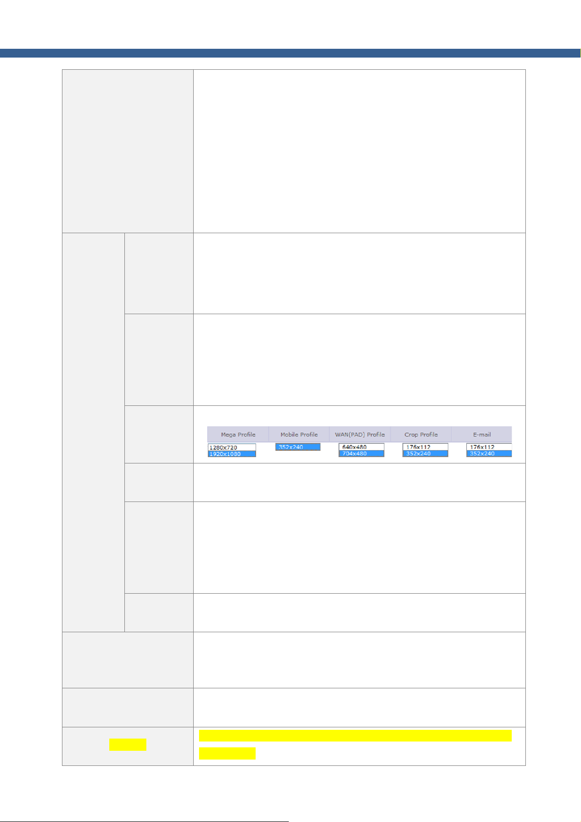
Maximum 5 different video profiles can be transmitted simultaneously
Video
Quality
Profile
VEnc. Type
Resolution
Frame rate
Video rate
through different video channel. Define the parameters for each video
profile.
E-mail profile is only used for e-mail transmission against Event.
Assign video codec for the channel. Either H.264 or MJPEG can be chosen.
Only H.264 is allowed for Mega Profile. As the use of MJPEG can be
limited only for certain software, please check it before selecting MJPEG.
If MJPEG is selected, “Video Rate” is automatically adjusted for
configured resolution and frame rate.
Assign the resolution of each profile.
Assign video frame rate. You can improve picture quality by lowering
frame rate for the same bandwidth.
Assign bandwidth for transmitting video data.
Higher the video rate ensure better video quality. But if you set the video
rate exceeding the Max. Upload Speed, the normal video transmission
Audio rate
Select Capture Profile
SAVE
Remarks
can’t be done. If the video is interrupted or mosaic, you need to lower the
video rate.
Assign bandwidth for transmitting audio data. Audio data is not
transmitted if you select “NA”
Select the video profile upon event.
Upon event, selected profile will be transmitted to FTP Server or stored in
(micro)SD Card.
Save the set-up parameters when parameters settings are finished.
You must click the “Save” once you finish all settings.
In case of 5mega pixel camera, the resolution is shown differently at the
mega profile.
Page 12
12
Network Camera_ User manual
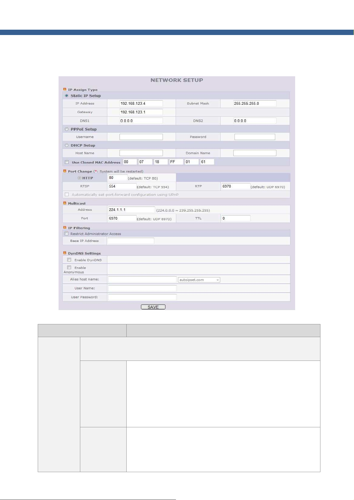
2.4. Network Setup
Setup the network parameters appropriately in accordance with your network environment. Many of the
parameters in this mode are same as those set up by “IP-Installer”.
IP Assign
Type
Fig. 2-4. Network Setup
Item Description
The network types supported by the products are LAN(fixed IP), PPPoE, and
DHCP(automatic IP allocation).
When the network environment is fixed IP, select ‘LAN’ in the network
type, and input the IP address, Subnet Mask, Gateway, DNS1 and
DNS2. Ask your network administrator or ISP for the information.
Static IP Setup
DNS2 is used when DNS1 does not work.
#. When you change the DNS, you should restart the camera
to apply the DNS.
When the network environment is PPPoE with automatic IP address
assignment, select ‘PPPoE’ in the network type and fill in the ‘User
PPPoE Setup
Name’ and ‘Password’ fields with the values given by your ISP. It is for
the use with ADSL modem.
Page 13

13
Network Camera_ User manual
When the DHCP server assigns IP address automatically, select ‘DHCP’
Port Change
DHCP Setup
Clone MAC Refer to [IP-installer user’s guide] for “Clone MAC”.
Port number should be positive integer below 65,535. Duplication of port number is
prohibited.
HTTP HTTP port is used for the connection to the admin mode. Default is 80.
RTSP
RTP
The range of Multicast address is 224.0.0.0 ~ 239.255.255.255.
Address
in the network type. Select this mode in case of Cable Modem.
Refer to [IP-installer user’s guide] for “Host name and domain for
Cable Modem.
The RTSP port is used for transmitting real time audio/video data from
the product. Default is TCP 554.
RTSP Address : rtsp://camera_ip_address[:rtsp_port]/StdCh<1|2|3|4>
The RTP port is used for transmitting real time audio/video data from
the product. Default is UDP 6970. It can be might not be used in some
environment.
The address is used for multi-casting real time audio/video data from
the product. Default is 224.1.1.1.
Multicast
IP Filtering
DynDNS
Setting
Port
TTL
You can restrict the access to the admin mode from IP addresses beyond certain IP
address range.
Restrict
Administrator
Access
Base IP
Address
You can register the product to the Management Server (DDNS Server) for name
service.
Enable
The port is used for multi-casting real time audio/video data from the
product. Default is UDP 6970.
Define number of routers multi-casting data pass through. Default is
0(off).
Check at this box to restrict log on to the admin mode.
Input IP address of the PC which is intended to be used for log on to
admin mode.
Enable / Disable DynDNS.
When enabled, you can automatically obtain a domain from DDNS
DynDNS
Setting
Anonymous
DynDNS
Enable
server by simply registering the network camera product.
Enable / Disable DynDNS Anonymous feature.
When enabled, DDNS service is used without going through
authentication at autoipset.com DDNS server.
Page 14

14
Network Camera_ User manual
If you want to register a hostname with a specific user account at
autoipset.com server, Please make an account from
(http://www.autoipset.com)
SAVE
Save the set-up parameters when parameters settings are finished.
You must click the “Save” once you finish the all settings.
2.5. 802.1x Setup
This is setup mode for IEEE802.1x authentication.
Item Description
Activation
CA Certificate Certificate for server verification.
Certificate
Setup
Client Certificate Certificate for client verification.
Private Key Private Key of client.
Select EAP type and configure Sub Fields.
EAP type
Fig. 2-5. 802.1x Setup
Check at the box to enable 802.1x authentication. If checked, this
product behaves as a client requiring authentication..
Select EAP type to choose authentication method. In order for
authentication to be successful, the client and the server must use the
same authentication method. Fields used in each method are as
Page 15

15
Network Camera_ User manual
Setup
Username Account name of client.
Password Password for the account
Private Key
Password
SAVE
followings:
EAP-MD5 : Username, Password
EAP-TLS : CA Certificate, Client Certificate, Private Key, Username,
Private Key Password
PEAP : CA Certificate, Username, Password
EAP-TTLS : CA Certificate, Username, Password
Password for Private Key.
Save the set-up parameters when parameters settings are finished.
You must click the “Save” once you finish the all settings.
2.6. Onvif Setup
Onvif protocol is open standard for communication between network video devices. It supports camera set,
configuration, real time viewing, PTZ camera control, etc. You can interoperate the IP Camera with Onvif
Standard Compliant NVR or CMS.
Authentication OFF : Camera does not require authentication for access.
Authentication ON (default) : Camera requires authentication for access.
Registered user accounts, including Administrator account, are used for authentication. To register
user account, please refer “2.8 User Admin & Time Setup” part of this manual.
Page 16

16
Network Camera_ User manual
2.7. Video Setup
You can adjust the parameters of input video. Note that parameters will vary in accordance with the
camera module employed.
Fig. 2-6. Video Setup
Video
Control
Item Description
Contrast Adjust contrast. Default is 50.
Brightness Adjust Brightness. Default is 50.
Saturation Adjust saturation. Default is 50.
Hue Adjust hue. Default is 50.
Select frequency of the power.
Power Line
Frequency
OSD Time Display
Blind
Power frequency can be different by each country. Correct one must
be choose for frequency
It can be selectable 50Hz or 60Hz. Default is 60Hz.
Enable/disable OSD time display and allocate the position of OSD
display.
Blind out some part of the video. Select the color for Blind mask. After
the color is selected, position the mouse to one corner then click and
drag the mouse to desired position and release button to select the
SAVE Save the settings.
Restore original values Click on “CONFIRM” to restore the default settings.
ISP Module Adjust Adjust the ISP module. Click to initiate..
area.
Page 17

17
Network Camera_ User manual
Fig. 2-7. ISP Module Setup
Item Description
WDR Set the WDR mode ON or OFF.
ISP
Control
Anti Flicker
Slow FPS
Sharpness
Auto Iris Set the Auto Iris ON or OFF
2DNR Set 2 dimensional noise reduction value.
3DNR Set 3 dimensional noise reduction ON or OFF.
Exposure
compensation at night
Synchronize the video frequency with Power Frequency of your
region to remove flickering. (OFF, 60Hz, 50Hz)
Enhance the Video image under the low light condition by
controlling the shutter speed.
Adjust the sharpness of video. The higher, the better video image.
Video can be noisier with higher value.
Set function Exposure compensation at night in accordance with
the installation environment.
For the product with default automatic function, the selection is
deactivated.
Change the camera exposure type.
Exposure Type
Set Shutter & Gain
Restore original values Click on “CONFIRM” to restore the default settings.
SAVE Save the settings.
AUTO : The exposure value is automatically adjusted.
SUTTER PRIO. : Only the shutter speed can be set and Gain value
will be adjusted automatically.
MANUAL : Sutter speed and Gain value can be set.
In the case of exposure type with manual will be activated.
Sutter speed and Gain value can be set.
Page 18

18
Network Camera_ User manual
2.8. User Admin & Time Setup
You can change the ID and password of users and also assign different attributes to each user. Once the
required setting-up is finished, please click the “Save” to save the setting values.
User
Administration
Fig. 2-8. User Admin. & Time Setup
Item Description
Administrator
Username
Administrator
password
Administrator
Confirm Password
Add User
Username
Add User
Password
Admin ID. Default ID is “root”
Admin password. The default password is “admin”.
Enter the password one more to confirm the password.
Enter user ID you want to add. Up to 100 users can be registered
in the product.
Enter user password.
Page 19

19
Network Camera_ User manual
You can assign different privileges to users for the access to
Authentication
for Viewing
Add User
system resources.
Attributes are Audio, Bi-directional Audio and Pan/Tilt control.
Attribute
For example, if you want a specified user to hear the audio
from the device, check Audio in the check box.
You can list “user ids” and “ their attributes” here.
format : user id[A, BA, P] :
A – audio,
User List
BA – bi-directional audio,
P – PTZ(Pan/Tilt/Zoom), attribute.
You can delete specific user by clicking on “DELETE” button.
If you want to restrict viewing access to the product, check at the
YES
box left to “Yes” and click on “Save”. Users need to input ID and
SAVE
password to connect to the product in viewing mode.
If you uncheck for the “Authentication for Viewing”, all users
If No, default
can access the product with the same default attribute. Checked
attribute
attributes are enabled. Click “Save” to save the default attribute.
Time Setup
Current Time It shows you the current time kept in the product.
Synchronize with
an Internet Time
Server
Synchronize With
this Computer
Time
Set Manually Set the time manually. Fill in the fields with desired formats.
SAVE
For maintaining more accurate time through continued time synchronization, set the time
synchronization with time server on the network or internet time server.
Synchronize the time kept in the product with the time kept in
time server on the internet at the right. When the time server is
out of the reach from the product, you can assign time server by
filling in “Specific Time Server” field.
Synchronize the time kept in the product with the time in the PC.
Save the set-up parameters when parameters settings are
finished. You must click the “Save” once you finish the all
setting-up.
If ID and Password are lost, you can set the system again torough Factory Default as the
following:
When the power is applied to product, press the Factory Default button for more than 3 sec,
then all Setting Parameters will be returned to Factory Default.
Page 20

20
Network Camera_ User manual
2.9. Sensor & Capture Setup
This is the setup mode for sensors and video capture conditions. Captured video can be sent to user by
FTP or (and) E-mail, or stored on local storage.
Sensor Setup
Video
Capture
Condition
Fig. 2-9. Sensor & Capture Setup
Item Description
Sensor 1
Name Input logical name of the sensor.
Set events initiating video capture for FTP, E-mail or storing in the local storage.
Sensor
Detection
Select
Motion
Detection
Select
Select sensor type. There are two types of sensors which are
Normal Open and Normal Close.
Enable/Disable Sensor event. Selected transmission is initiated only
when sensor is activated. Select desired transmission methods for
sensor event.
Enable/Disable Motion Detection event. Select desired transmission
methods for motion event.
Page 21

21
Network Camera_ User manual
Video
Capture
Condition
Transmission
Method
Pre-Post
Audio
Detection
Select
Select a way of sending captured video
E-Mail
Transmission
FTP
Transmission
Built-in
Storage
Play Alarm
Sound
MOTION
SETUP
E-Mail /
FTP
Enable/Disable Audio Detection event. Transmission methods applied
for motion event is applied for transmission.
Transmit to the desired E-mail address configured at
[Network Configuration]
Transmit to the desired FTP Server configured at
[Network Configuration]
Save the video into built-in SD Card.
Generate Alarm Sound through Speaker. This function is only available
in the products having built-in Speaker.
Move to Set-Up Menu for configuring Motion Detection Zone.
Total 20 second of video data is transmitted through E-mail.
Post recording time is automatically adjusted in accordance with the
pre-recording time.
Recording
Time
SD Card
Management
Pre and Post recording time is independently configurable when
Built-In
Storage
SAVE
SD Card
Format
SD Card
Status
SD Card
Unmount
SD Card Usage Display the Usable/Used Space of SD Card.
recording into built-in SD card. The Pre-Recording can be selected from
5, 10, 15 sec, while post-recording time can be selected from 10, 15,
20, 30, 60 sec.
Save the setup parameters.
You must click on “SAVE” to apply the setting values.
Format the SD Card for Use.
All New SD Card need to be formatted at least 1 time.
Display the status of SD Card on the product.
Detected : SD Card is recognized.
Not Exist : No SD Card or Not Recognized.
Error : Unable to use SD
Unmount the SD Card to eject the SD Card safely. To prevent the Data
Loss and damage of SD Card, you must do the Unmount procedure
before ejecting the SD Card.
Configure event schedule.
Schedule
Alarm Setting
Type
Select type of event to set schedule among Continuous Recording,
Sensor, Motion Detection.
Page 22

22
Network Camera_ User manual
Day Select Date
Time
SAVE
Set time begin and end time. The time can be set in the increment of
30 minutes.
Save the setup parameters.
You must click on “SAVE” to apply the setting values.
2.10. E-Mail & FTP Setup
Configure E-mail and FTP connection information.
E-Mail
Setup
Fig. 2-10. E-mail and FTP Setup
Item Description
If you check this, the IP address will be sent via E-mail whenever the
Notify for IP
IP address changes. It is sent to the E-mail address set in
Change
“Recv E-Mail Address”.
Recv E-Mail
Enter destination E-mail address to send information from your product.
Address
Fill in this field with active and valid e-mail address to identify sender of the
e-mail. Typical e-mail address will be the e-mail address of the owner or the
administrator.
Return E-Mail
Note that the e-mail message from the product might not pass through the
Address
SPAM filter of the receiver’s e-mail server, when this field is not filled in with
active e-mail address.
Page 23

23
Network Camera_ User manual
If you are using web mail services having no SMTP server, check the radio
button at the left of “Using Built-in SMTP Server” and enter active and
valid e-mail address to avoid spam filtering on the receiving e-mail server.
If you are using external mail server, fill in the fields with proper parameters.
Use only for the changed use of default port of E-Mail Server.
Setup IP address, Username, Password and Directory of FTP server to send
captured video data. Default FTP port number is 21.
Save the setup parameters.
You must click on “SAVE” to apply the setting values.
E-Mail
Setup
FTP Server Setup
Using Built-in
SMTP Server
Using
External
SMTP Server
Using SSL Check only for the request of using SSL during the Log On by SMTP Server.
E-Mail Port
No.
SAVE
2.11. Alarm Device Setup
Test the alarm output and describe the condition of alarm annunciation.
Fig. 2-11. Alarm Device Setup
Item Description
Test alarm devices. Click on On/Off for testing.
Alarm Device
ON On the alarm output (close the relay contact)
Test
OFF Off the alarm output (Open the relay contact)
Set up the condition of activating each alarm device. Select sensor or motion detection.
Alarm Device
Active
Condition
Name Logical name of the alarm device can be input into the box at the left.
Sensor When checked, alarm device is activated upon sensor input.
When checked, alarm device is activated upon Motion, Audio Detection
Motion
or PIR detection.
Page 24

24
Network Camera_ User manual
Duration Set the duration of Alarm annunciation.
SAVE
Save the setup parameters.
You must click on “SAVE” to apply the setting values.
2.12. Motion Detection Setup
Set the motion detection regions. Up to 3 regions can be defined.
Item Description
Channel Sensitivity
Motion
Region
Up to 3 motion detection zones can be configured.
Fig. 2-12. Motion Detection Region Setup
Set the sensitivity of motion detection for each channel. Default is 6.
The Higher the value, the higher the sensitivity.
Note that false motion alarm can be generated if the sensitivity is set to
be unnecessarily high. You are recommended to set the sensitivity to most
appropriate value after test.
Region Click on “SELECT”, then click & drag on the Video to select the region.
Page 25

25
Network Camera_ User manual
Setup 1, 2, or 3 Even you configure the region, motion detection will not be enabled if you
don’t check the box.
Legend of the color : 1 : Red, 2 : Green, 3 : Blue
ALL
Selection
ALL Clear Erase the configured region.
Test a
Region
Percentage
SAVE
Set entire region of video as motion region.
This will help you to find out by several testing about how many percent
is needed to detect motion in your view sight.
Set how many percent of change in the video will be recognized as motion
in the configured region. This value controls the sensitivity of each region.
Default is 50%.
1 is the most sensitive and 100 is the least sensitive.
Note that false motion alarm can be generated under noisy video when
the value is small.
Save the setup parameters.
You must click on “SAVE” to apply the setting values.
Page 26

26
Network Camera_ User manual
2.13. Audio Detection
Set the audio detection level. Audio detection is treated as a motion detection in the system.
Audio Detection
Threshold
Set Threshold
Fig. 2-13. Audio Detection Setup
Item Description
Set the sensitivity of audio detection for each channel. Default is 50.
The Lower the value, the higher the sensitivity.
Note that false audio alarm can be generated at unnecessary high sensitivity,
so you need to set the value to most appropriate level after testing.
Audio input level is drawn in as a bar graph. Set the threshold level. Audio
detection event is generated if input audio exceeds threshold level which is
indicated as a red horizontal line.
Page 27

27
Network Camera_ User manual
2.14. PTZ Setup
PTZ Setup is available on the models having Pan/Tilt/(Zoom) functions. You can configure PTZ
parameters using Web Viewer or NVR-pro, too.
PTZ Model
Selection
PTZ Device ID
PTZ Baud Rate
PTZ Operation
Check
Fig. 2-14. PTZ Setup
Item Description
Select the Protocol which is used by PTZ Camera.
Delete Button Delete the displayed PTZ Protocol.
Your PTZ device needs an ID. Input ID in this field.
Click on SAVE to save the ID.
If PTZ ID does not match, it won’t operate normally.
Configure the RS-485 Baud Rate for PTZ control.
If the PTZ Baud Rate does not match, it won’t operate normally.
Speed Select this RADIO button to set the speed of the PTZ operation.
Step Select this RADIO button to set the step size of PTZ operation.
PAN Move the slider to adjust the speed or step in panning.
TILT Move the slider to adjust the speed or step in tilting.
ZOOM Move the slider to adjust the speed or step in zooming.
Page 28

28
Network Camera_ User manual
2.15. Upgrade & Reset
You can upgrade the device via the IP network.
Upgrade is a process to renew the System Software stored in the non-volatile memory of the system.
You must restart the system by “System Restart” to run the system with the upgraded system software.
Fig. 2-14. Upgrade & Reset
Contents of the upgradable system component should be downloaded from CNB’s home page before the
system upgrade is performed.
Item Description
Upgrade the system manually.
Manual
Upgrade
System S/W
Upgrade
ActiveX
Firmware
Upgrade
Bootloader
Upgrade
Add PTZ File
Upgrade the system software installed on the product via the network.
Upgrade the system software installed on the product via the network.
Upgrade the bootloader installed on the product via the network after
getting from CNB. Generally it is not required to upgrade the Bootloader.
For the PTZ Applicable product, you can use PTZ by uploading extra
protocol. (Applicable product will get it a activated automatically)
System Variable File Upload This loads up setting from a saved “Download template file” file.
Page 29

29
Network Camera_ User manual
Factory Default Setting
System Restart
The upgrade of product will change the F/W or other programs installed on the system. To
operate the system with the changes, you must perform “System Restart” after the upgrade.
Re-initialize the system to factory default state.
By checking on a Radio button “Except Network Configuration”, you can
preserve the parameters for the network in case of remote upgrade.
Checking on “All”, will return all the parameters to factory default state.
Once all the values are set to factory default state, the product
should be set-up again using IP-Installer.
Perform remote reset by clicking on the “CONFIRM” button.
[Important] To apply upgraded contents, you should perform
System Restart.
All previous connections will be disconnected upon reset. Device
does not resume the connections and the user must re-connect
to the product manually.
After restoring the Factory Default, if you need to access to the product with the same access
information, you must select “Preserver Network Configuration”.
If you do the Factory Default by selecting “All”, all network parameters will be initialized, you
need to assign the network parameters again for use of the product.
Page 30

30
Network Camera_ User manual
<Upgrading the Product>
Unless otherwise instructed, the owners of the device are recommended to upgrade the system when
upgraded firmware is released using manual upgrade procedure.
Followings are the procedure to apply for the manual upgrade
1. Save the upgrade system software to your PC. Upgrade software can be downloaded from CNB’s
home page or provided in CD.
2. Connect to the product in admin mode and select “Update & Reset” menu.
3. Click "Browse..." to find the files you want to use for upgrade. This will open a "Choose file" dialogue
window. The file extension is “ief” for the case of system firmware.
4. When you've found the file, click "Open." This will select the file and close the "Choose file" dialogue
window.
5. Click the "INSTALL" button. An alert message box will pop up. Click “OK” button then it will start
uploading the file. This may take some time.
6. Upgrade completion message will appear after the system upgrade has been completed.
7. Reboot device by performing “System Restart”.
8. After rebooting, log on to the product in admin mode again and click the “Status Report”.
9. Check the version number and release date of the firmware.
If the administrator restart the product, the connection of all users to the product will be
disconnected. As the connection won’t be restored automatically after the re-booting, users
must re-connect with product.
Page 31

31
Network Camera_ User manual
2.16. Status Report
It shows you system records since the system started.
Fig. 2-16. System Status Information
With this System Status Information, you can check whether the system upgrade has been done correctly
or not, as well as the versions and event status of the whole system and modules.
Item Description
Download template file This saves current camera’s configuration to Client PC as files.
Page 32

32
Network Camera_ User manual
3. Web Viewer
3.1. Web Viewer
IP camera and video server provide video connection over the internet explorer. The web viewer might be
different on different product.
Video crop function is available from the web viewer.
Control Keys
Admin Mode Connection
Fig. 3-1. Web Viewer-1
Video Crop Control
PTZ menu
Fig. 3-1. Web Viewer-2
Page 33

33
Network Camera_ User manual
3.2. Buttons and Indicators of Web Viewer.
Item Description
On/Off control of bidirectional audio communication. Bidirectional
audio communication is enabled when highlighted.
If the microphone is not connected to PC to set up the bidirectional
audio, an error message is indicated and the temporarily stopped
image my occur.
If the video is stopped, should “refresh” the webpage or
“re-connection” to play the video.
Capture a still video cut. Captured video is stored in the folder
designated in [2.3. Basic Setup]
Rotate the video by 180o.
Start Crop Video. Crop video is always transmitted through channel 3.
Set the coordinate of the top left corner of the crop video.
Set the size and frame rate (frames/sec) of the crop video.
Minimum and maximum size is 172x112 and 352x240.
Click to start transmission of crop video on channel 3.
Click on the button to connect to the channel. If crop video is
enabled, it is available through channel 3.
Disconnect the video.
Contrast and brightness adjustment. The adjustment value is stored
on the PC.
Volume control and audio mute control.
Adjust the size of the video.
Shows the status of the sensor. Highlighted color indicates that the
sensor is activated.
On/Off control of the relay. Highlighted color indicates that the relay
is “On”.
Page 34

34
Network Camera_ User manual
3.3. Crop Video Setting
The position, size and the frame rate of the crop video can be set in the web viewer. The blue area in the
figure below shows the crop window from a 1920x1080 image sensor. Set the position as (250, 250) and
the size as the desired. After the setting, click on ( ) to start video transmission
Fig. 3-3. Example of the Crop Window
NVR-Pro offers more advanced interface to the use of crop video by Mouse Click..
Page 35

35
Network Camera_ User manual
3.4. PTZ Control Menu
You can control the PTZ of PTZ-enabled product by using PTZ menu control buttons on the Web Viewer.
Item Description
Camera Position Control
Pan/Tilt control
Zoom In
Zoom Out
Focus Far
Focus Near
Enter into OSD menu for camera setting.
In the OSD menu, use Up/Down buttons to navigate through the menu item on
the screen.
Depending upon the situations Left/Right buttons will perform one of the
followings.
1. Change parameter value in each submenu.
2. Decrement/increment the numbered value.
3. Go into lower level menu trees.
4. If clicked when the cursor is on “EXIT”, upper menu will be activated or OSD
menu mode will be finished.
For more detailed information, refer to the product manual.
If the product can’t support the OSD menu, “Menu” button is disabled.
After activating this mode, the camera will move so that the clicked point on the
video is located at the center of the video. display.
Left : Deactivated.
Right : Activated.
Iris Control
Set Pattern
Set Tour
Set Preset
GOTO Preset
Run Pattern
Run Tour
Run Scan
Page 36

36
Network Camera_ User manual
Stop any PTZ command
Enable Auto PTZ
Tracking
Auto PTZ Tracking
Setup
1. Pattern Setting Procedure (Pattern is a recorded sequence of PTZ operation steps)
a. Choose Number to be assigned as Pattern ID.
b. Click “SET PTRN” button to start recording the pattern. The OSD menu will appear on the screen.
c. Operate the camera using Pan/Tilt/Zoom Control.
d. Click “SET PTRN” again to save the pattern.
2. Tour Setting Procedure : (Tour is a series of Preset)
a. Choose Number to be assigned as Tour ID.
b. Click “SET TOUR” button to start tour setting. The OSD menu will appear on the screen.
Enable Zoom
Control
If no motion
Check for using auto tracking function
Check for zoom control
If there is no motion, camera comes back preset position.
Select second and preset you set.
c. Choose preset number and Click “GOTO PRST”.
d. Repeat procedure “c” to assign a series of preset positions to the tour.
e. Click “SET TOUR” again to save the tour.
3. Preset Setting Procedure
a. Choose Number to be assigned as Preset ID.
b. Pan/Tilt/Zoom Control.
c. Click “SET PRST” button to save the preset position.
< Detailed Setup >
Item Description
You can change the setup of configured Tour
After you select the setting value of “Tour No. / Step No. / Setting Value”
in sequence, click the SET button to set.
You can change the setting of configured Auto Scan in OSD Menu.
Set the Start/End Point of Scan mode. The coordinate value
is displayed at the bottom of the screen. Scan area is
changed in accordance with the rotational direction setting
of endless. Out of the two scanning regions (narrow region
defined by small angle and wide region defined by large
Page 37

37
Network Camera_ User manual
angle). If counterclockwise direction was set, the scanning
covers the wide region, while the scanning covers narrow
region if clockwise direction was selected.
Note : Endless Function of OSD Menu should be
Off.
Select the rotational direction of camera, when Endless
Rotation is On.
Activate/Deactivate the Endless Function.
The configured status can be checked only on OSD Menu.
Activate/Deactivate the Flickerless Function.
Activate/Deactivate the BLC Function.
Activate/Deactivate the WDR Function.
This function is available on some specific products.
Activate/Deactivate the DSS Function.
Reverse the Left/Right of Video.
Reverse the Up/Down of Video.
When passing over the 90 degree as the limited point of Tilt
operation, it will rotate the camera by 180 degree for
continuous movement.
Activate/Deactivate the Digital Zoom of Camera Module.
Change the Setting Value of Camera Module.
Select the category to change and select the Setting Value, then click on
SET button.
Designate or change the PTZ Operation against each Alarm Input.
Set the N.O. / N.C. as activation condition and select the PTZ Command
to perform accordingly, then press SET to save the setting value.
Enable/Disable the Alarm.
For the Alarm Triggered operation, alarm should be enabled.
Add or Change the Setting of Privacy mask.
Select the number of the mask to set then click on SET. The Privacy
Setting is displayed on the Screen.
Page 38

38
Network Camera_ User manual
DISPLAY Display region for privacy mask.
Move or Adjust the position and size of privacy mask by
selecting MOVE and ADJUST.
ACTION
SAVE You must save after changing any setting.
Change the area of Sector configured on OSD Menu.
The character strings displayed by the Sector function can be changed
only through OSD Menu.
Delete the settings for Preset, Tour, Pattern, Privacy, or Sector
configured in the camera selectively or altogether.
Enable/disable display of Camera ID, Preset ID, Sector ID, and
Coordinate information.
Check/uncheck on small box at the left of each subment, then press the
SET button to configure.
Lock access to OSD Menu.
Enter password which is a number from 1 to 200. Then press SET
To adjust the size, select ADJUST and press the Focus Far
button, Adjust the size using PT Direction Key and
ave by pressing the Focus Far Button.
button. Activate/deactivate the System Lock by pressing the LOCK
button.
If you want to go into OSD Menu under the System Lock Status, you
need to perform Goto Preset to selected number for password.
Restart the Camera Module and start operation.
Page 39

39
Network Camera_ User manual
2
4. Trouble Shooting and Tips
4.1. Trouble shooting after installation
4.1.1. Neither channel name nor video is shown up and eventually timeout message is sho
wn
up.
1. Check the power and network connection of device.
To check if the network is properly operating, open the browser and try to connect to any server.
Example) http://www.google.com
Or open the MS-DOS Prompt and type the following
ping www.google.com
Then press Enter. If you see the “ Reply from … ” message it means that the network is working
properly. To check if the device is connected, open the MS-DOS Prompt and type the following
ping [the IP of the server]
Example) ping 192.168.1.112
2. If you see the “Reply from …” message, it means that the server is properly connected.
If you do not see a Reply message, check if the network cable and power cable are properly
connected.
1
Page 40

40
Network Camera_ User manual
4.1.2. The name of the server is shown but no video is available (Only the Frame of Web
Viewer)
In this case, network connection is not a problem. Please do the followings:
Check whether the video is properly applied into the product.
Check whether there is firewall between the product and the client and check whether the network
is NAT type.
Connect to the product through TCP. (Actually only TCP is available presently)
If the network type is NAT, “port mapping” should be done. The NAT server will send the packet
through specific port to the product through “port mapping”. IP sharing device has the “port
mapping” function in general. Details of the procedure can be found from the manual of the IP
sharing device.
4.2. Trouble shooting after successful connection to the device
4.2.1. Video movement is slow
In Basic Setup of Admin Mode, lower the “Quality”. High quality means more data. You can also set
the “Max. upload rate” to higher value. But this value must be lower than the maximum upload speed
of your network. For example, if the maximum uploading bandwidth of the network is 400Kbps, set
the total “Max. upload rate” as 384Kbps. If you set it higher, the video image can be corrupted with
artifacts.
Ask your network manager or ISP for maximum uploading bandwidth of the network.
4.2.2. The image is dull and I see green, pink dots
This could be caused by performance limitation of the PC. Do not run too many programs while
running viewer program. The other reason could be missing data in the transmission from the device.
4.2.3. Mosaic phenomenon
Mosaic phenomenon occurs when not enough network bandwidth is available considering the
resolution and frame rate of the video.
Example is 704x480 video with low Max. upload rate.
Users are recommended to adjust resolution and frame rates to lower values for lower bandwidth
network
 Loading...