

Page 1
Ver. 1.0
XNET Network Weatherproof Camera
(IXP3035VR)
Installation Manual
Page 2

XNET Network Weatherproof Camera Installation Manual
About this Manual
This product has been tested for compatibility and stability as per CNB’s high performance standard.
This installation guide covers the installation and operation of XNET Network weatherproof Camera
only.
Please read this manual including the important cautions and warnings thoroughly before using the
product even if you are an expert.
Important Notices
The copyright of this manual is owned by CNB Technology Inc.
It is illegal to copy and distribute this manual without permission.
Damages caused by misuse (i.e. use of parts not suggested) will not be covered under warranty.
Contact the store or the manufacturer immediately if there is any problem with the product.
Do not disassemble the product for alteration or repair.
XNET is a trademark of CNB Technology Inc.
This product complies for CE (Europe) and FCC (USA) regulations for industrial and home electrical
device.
INFORMATION
This equipment has been tested and found to comply with the limits for a Class A digital
device, pursuant to Part 15 of the FCC Rules. These limits are designed to provide
reasonable protection against harmful interference when the equipment is operated in a
commercial environment. This equipment generates, uses and can radiate radio
frequency energy and, if not installed and used in accordance with the instruction
manual, may cause harmful interference to radio communications. Operation of this
equipment in a residential area is likely to cause harmful interference in which case the
user will be required to correct the interference at his own expense.
2 / 23
Page 3

XNET Network Weatherproof Camera Installation Manual
Index
1. About XNET ...................................................................................................................... 4
1.1. About XNET ............................................................................................................................. 4
1.2. Features of XNET .................................................................................................................... 4
1.3. Applications .............................................................................................................................. 4
2. Product Description ........................................................................................................ 5
2.1. Contents ................................................................................................................................... 5
2.2. Product Information .................................................................................................................. 5
2.3. Hardware Designation .............................................................................................................. 6
2.3.1. Switch and Controls ..................................................................................................... 6
2.3.2. Internal configuration ................................................................................................... 7
2.3.3. Connecting to Cables ................................................................................................... 8
2.3.4. Alarm Device Connection ........................................................................................... 10
2.3.5. Adjusting Zoom and Focus ........................................................................................ 11
2.3.6 Mounting the Camera ................................................................................................. 11
3. Software Installation ...................................................................................................... 13
3.1. Installing XNET system .......................................................................................................... 13
3.2. IP-Installer and IP address Configuration ............................................................................... 18
3.2.1. About IP-Installer ........................................................................................................ 18
3.2.2. IP Address Configuration ........................................................................................... 18
4. Using Web Viewer .......................................................................................................... 20
4.1. Logging In .............................................................................................................................. 20
4.2. Web Viewer Page ................................................................................................................... 21
5. Specification .................................................................................................................. 22
3 / 23
Page 4

XNET Network Weatherproof Camera Installation Manual
1. About XNET
11..11.. AAbboouutt XXNNEETT
XNET is an internet based security and surveillance system presented by CNB. XNET is compatible with
various networks with its easy installation, various user interfaces, and multi-functional compressor Codec
such as H.264 and MJPEG. XNET provides reliable real-time surveillance by SXGA real time video/ audio,
event-based local storage, and hybrid IP technology that can be used with the existing analog CCTV systems.
11..22.. FFeeaattuurreess ooff XXNNEETT
Advanced Video/ Audio compression technology (MJPEG/H.264, G.711)
Progressive technology - Sharp and clear image with no ghost effect.
Hybrid IP Technology –Analog CCTV video output for connecting to an existing analog system.
Multi-Codec stream - Live video signal compression to MJPEG or H.264 for various applications.
2-way Audio - Bi-directional voice communication between Client’s PC and XNET device
Smart Event feature - Motion detection, Alarm sensor/output, pre- and post- alarm for automated
surveillance with no need for an attendant or monitoring.
Installation Wizard – Easy and unified installation for large network.
Motion Detection with three different areas – Alarm output and Video/ Audio data transmission to FTP site
or e-mail.
Supports Various resolutions
- SXGA(1280x1024), 720p(1280x720), D1(720x480), VGA(640x480), CIF(352x240)
RS-485 interface for Remote Pan/Tilt control
Remote firmware upgrade over the network
11..33.. AApppplliiccaattiioonnss
Surveillance (Surveillance areas can be a building, store, factory, parking lot, financial institutions,
government buildings, military facilities, etc.)
Remote video monitoring (Monitoring areas can be a hospital, kindergarten, traffic monitoring, remote
branch office, weather, environment preservation, illegal disposal of trash, etc.)
Real time broadcasting over the internet (Broadcasting can be from a resort facility, parties, festivals,
remote business meetings, educational trainings, etc.)
4 / 23
Page 5
XNET Network Weatherproof Camera Installation Manual
2. Product Description
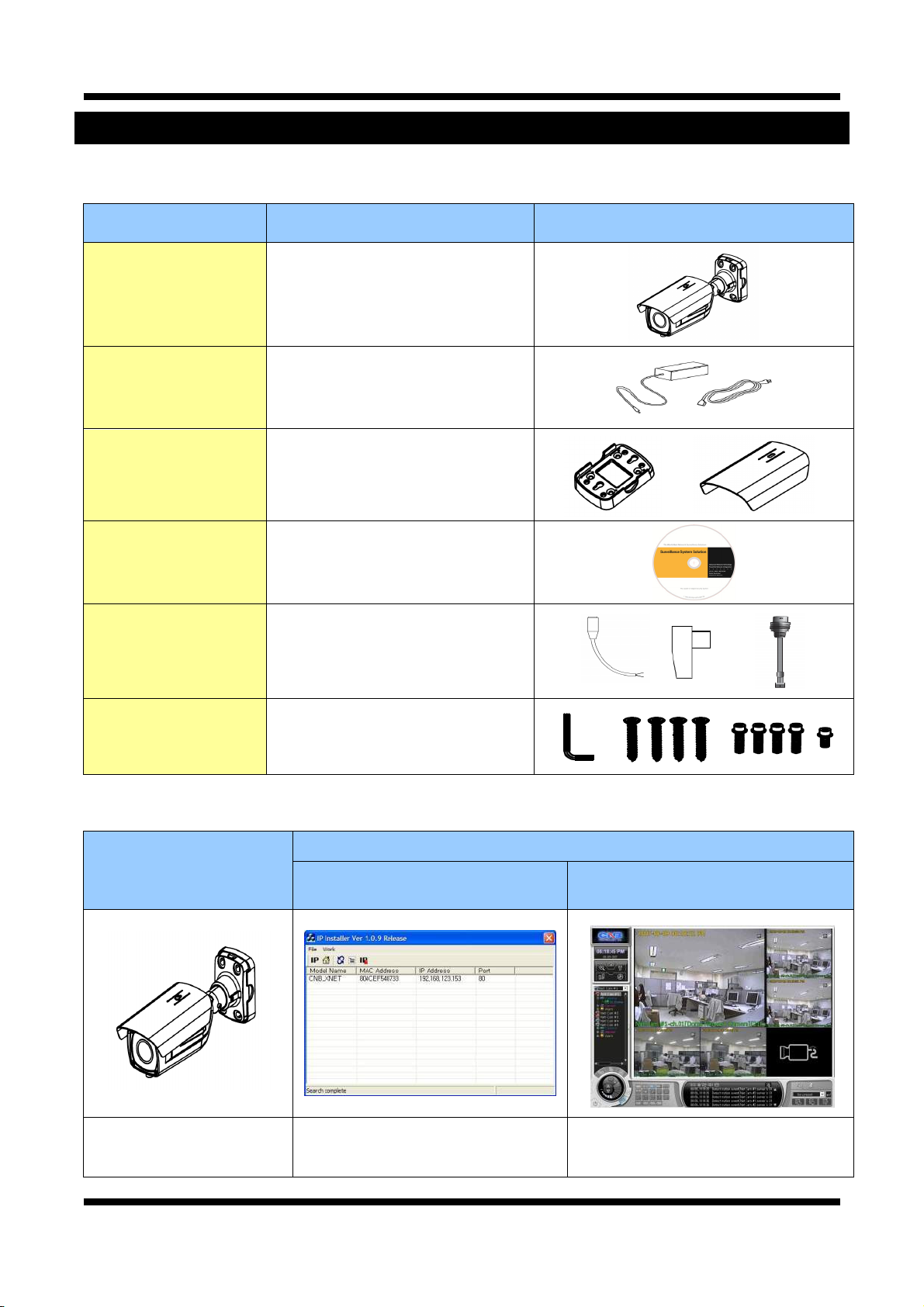
22..11.. CCoonntteennttss
Please make sure the following contents are included in the package.
Contents Description Additional info.
POWER ADAPTOR
AC Power Cable
BRACKET, SUNVISOR
DC Plug
DC CONNECTOR
CVBS Cable
Accessory
XNET XNET IP Camera – Main body
INPUT : 100~240VAC 50-60Hz
OUTPUT : 12VDC 2A / AC24V 2.5A
CD Software and User’s manual
2 Jack Power Cable for Outlet
BRACKET BASE:1EA
SUNVISOR : 1EA
A Plug for DC Power Adaptor
Two Position Connector for Power
Input
BNC connector for Analog Video
Output
L-WRE N CH : 1EA
SCREW 4EA
Wall Anchors 4EA
Sunvisor Screws : 1EA
22..22.. PPrroodduucctt IInnffoorrmmaattiioonn
XNET
(IXP3035VR)
IP Weatherproof Camera
(IXP3035VR)
Install CD
IP-Installer
A software for detecting the XNET
camera in the network and assigning
an IP address
Viewer Program
(CNB-CMS)
A software to monitor/record live Video
and audio from the XNET camera
5 / 23
Page 6
XNET Network Weatherproof Camera Installation Manual
22..33.. HHaarrddwwaarree DDeessiiggnnaattiioonn
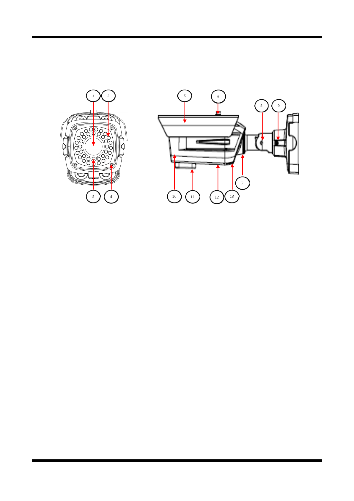
22..33..11.. SSwwiittcchh aanndd CCoonnttrroollss
① Vari-focal Lens : 3-10mm Vari-focal Lens
② IR LED : IR Led light controlled by CDS Sensor.
③ CDS Sensor : senses the light intensity (low light level).
④ Casing Screws (front - 4EA) : attach the front and rear bodies together
⑤ Sunvisor : Shields off the direct sunlight to avoid overheating the camera module
⑥ Sunvisor Screws : fix the Sunvisor on the main body
⑦ Rotate adjusting Bolt: fixes the adjustment of the camera’s rotational angle.
⑧ Tilt adjusting Bolt: fixes the adjustment of the camera’s tilt angle.
⑨ Pan adjusting Bolt: fixes the adjustment of the camera’s pan angle.
⑩ FRONT BODY
⑪ Zoom & Focus lever access: Please refer to 2.3.5. Adjusting Zoom and Focus
⑫ Connecting Terminal: Please refer to 2.3.2. Connecting Terminal
⑬ REAR-BODY
6 / 23
Page 7
XNET Network Weatherproof Camera Installation Manual
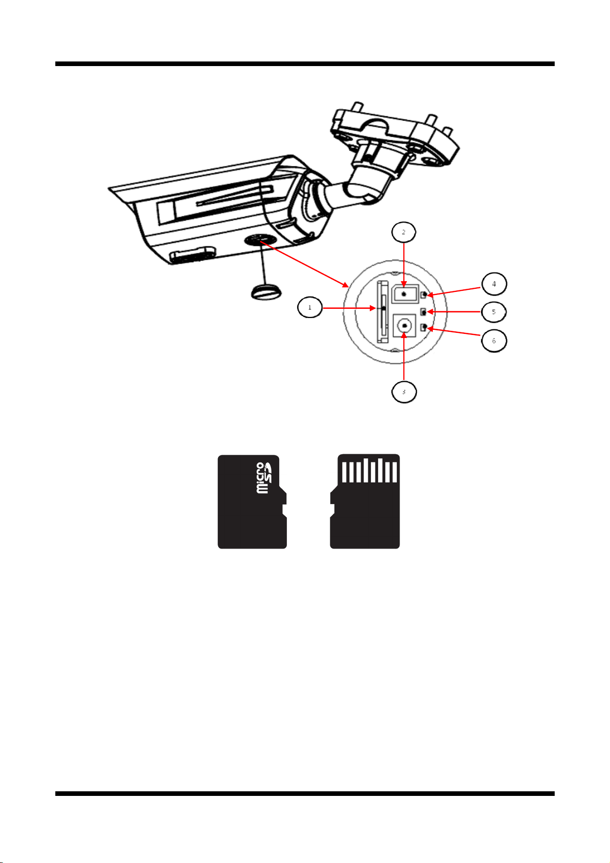
22..33..22.. IInntteerrnnaall ccoonnffiigguurraattiioonn
Micro SD Card Slot :
①①
Video images can be stored into a Micro SD card when an event occurs. Please use less than 16 GB
MICRO SD Memory.
Figure 2-3. MICRO SD CARD
Video Out: Analog Video output. When installing the camera, use this output to connect a CCTV
②②
monitor to quickly check for desired image. The enclosed CVBS cable has an RCA termination.
(Enable Video Out in Camera’s menu to activate this Analog video output. The analog Video can only
be used in resolutions lower than VGA.)
Factory Reset Button : When the Camera is powered up, press and hold this button for 3 seconds
③③
to reset the camera to factory default state
PWR LED: Red light indicates that 12V DC/24V AC power is connected.
④④
LINK LED: Red light indicates that the network is properly connected.
⑤⑤
ACT LED: Green light indicates that the XNET system is connected to 100Mbps LAN. Also, the blinking
⑥⑥
green light indicates that the system is receiving data.
7 / 23
Page 8

XNET Network Weatherproof Camera Installation Manual
22..33..33.. CCoonnnneeccttiinngg ttoo CCaabblleess
INPUT, OUTPUT
Alarm, RS-485 Connection
These wires connect to Alarm input/output devices.
Alarm Sensor Input: Connect to an Alarm sensor device such as an IR Sensor or a Heat sensor. The
operation of this input can be configured to either normally close or normally open.
Alarm Output: Connect to a relay that drives alarm devices such as a Siren Lamp or an Alarm Light.
The operation of this output can be configured to either normally close or normally open.
Please refer to “2.3.4 Connection to Alarm Devices” for detailed instruction on how to connect a
sensor and a relay.
RS-485: Connect a Pan/Tilt device with RS-485 interface, so it can be controlled over the network.
POWER IN VIDEO OUT
Power Input
diagrams below: (DC12V/2A, AC24V 2.5A)
Use the cable adapter (DC12V JACK) in the package to connect power.
Please use the power supply provided in the package.
When connecting to a power supply, please note the following power ratings and the
Do not use this connector when powering up the product through LAN cable. (PoE)
The product is not covered under warranty when it is damaged by connecting both
Ethernet power and 12V DC power to this terminal.
8 / 23
Page 9

XNET Network Weatherproof Camera Installation Manual
Analog Video Output
This output can be used to check the video during the installation.
Use the supplied BNC connector
Connect the adapter to a video cable with BNC termination.
(Select Video Out in menu to enable this output)
Audio Connection
MIC/Line Input (Mono) RED
Connect this wire to the Audio input. The audio input can come from a microphone or an Audio device.
Line Output (Mono) WHITE
This is an Audio signal output to a Power Amplified device or a Speaker. In two way audio
communication using the XNET system, this can be used to listen to the audio from a remote PC.
Network Cable
This RJ-45 Ethernet terminal connects to a 100Mbps LAN. When an optional PoE is used, the power will be
supplied from the Network Cable. Network cable of this product is not water-resistant.
Do not connect anything to power connector when the product is getting its power
from LAN cable. (PoE) The product is not covered under warranty when it is
damaged by connecting Power over Ethernet and another power supply at the same
time.
9 / 23
Page 10

XNET Network Weatherproof Camera Installation Manual
22..33..44.. AAllaarrmm DDeevviiccee CCoonnnneeccttiioonn
Alarm Input
Various alarm sensor types (IR, heat, magnetic, etc.) can be connected to Alarm input (+)/(-) terminal as
shown in figure 2.5. (NC or NO can be configured in Menu.)
Please note that the Alarm Sensor device requires a separate power source.
Internal Circuitry External Circuitry
Alarm Output
This terminal can only drive up to DC 30V/400mA. A relay has to be used to operate Alarm devices that
require higher voltage or current.
Internal Circuitry External Circuitry
10 / 23
Page 11

XNET Network Weatherproof Camera Installation Manual
22..33..55.. AAddjjuussttiinngg ZZoooomm aanndd FFooccuuss
Zoom and focus of the lens can be adjusted at the bottom of the camera as shown in the picture. Use a flat
head screw driver to turn the lever.
22..33..66 MMoouunnttiinngg tthhee CCaammeerraa
Sunvisor
Install Sunvisor to the Camera’s main body using Sunvisor, washers, and screws.
11 / 23
Page 12

XNET Network Weatherproof Camera Installation Manual
Mounting the Camera
Ceiling Mount type Wall Mount Type
Mount the Bracket Base on the installation surface using the four 6mm screws provided.
Mount the camera’s main body on the Bracket Base using the four 5/16” screws provided as shown in the
figure.
Adjusting the Camera Angle
Ceiling Mount type Wall Mount Type
After mounting the Camera, unlock the fixing screws shown in the picture using the L wrench provided to
adjust the camera’s angle as desired. Tighten the fixing screws back when done.
12 / 23
Page 13

XNET Network Weatherproof Camera Installation Manual
R
3. Software Installation
This is a quick installation guide for XNET software. XNET software helps you monitor the XNET’s Video and
Audio in an easy user interface. If you have questions about details not explained in this section or if the
product is not functioning as described, please refer to FAQ on our homepage at
before contacting the store.
33..11.. IInnssttaalllliinngg XXNNEETT ssyysstteemm
Connecting the XNET camera Directly to a PC
The XNET camera can be directly connected to a PC for configuration.
1. Connect the XNET camera to your PC directly using a crossover LAN cable as shown below.
NOTE: The XNET camera will set its IP address to the default value,
192.168.123.100, after looking for a DHCP service.
(This process approximately takes 20~30 seconds)
Crossover
COMPUTE
Network Cable
http://www.cnbtec.com
2. Next, change the PC’s network configuration in the following window:
Windows Start Control Panel Network Connections Right-clicks on the Local Area Connection
icon Double click on the Internet Protocol (TCP/IP) icon.
Set PC’s network configuration as below:
13 / 23
Page 14

XNET Network Weatherproof Camera Installation Manual
NOTE: IP address of the PC can be set in anywhere between 192.168.123.2 and
192.168.123.254 except for 192.168.123.100, which is taken by the XNET camera.
3. Insert the Setup CD into your CD-ROM drive, and install
IPInstaller software.
4. Click ‘Next’ when the Installation Wizard box pops up.
5. Click ‘Install’ to begin the Installation.
6. Click ‘Finish’ to complete the installation.
14 / 23
Page 15

XNET Network Weatherproof Camera Installation Manual
7. XNET IP Installer will launch automatically as shown below. Double click on the XNET camera from
the list.
15 / 23
Page 16

XNET Network Weatherproof Camera Installation Manual
8. When the XNET camera is successfully connected to your PC, you’ll see the camera’s IP address on
the IP installer software.
(Internet Explorer will prompt you to install ActiveX.
Please accept the ActiveX download in order to view video. )
NOTE: Click on Setting in the main screen to change the configurations of the XNET
camera.
Enter the default User name and Password when the login prompt opens up.
Default User name : root Default Password : admin
16 / 23
Page 17

XNET Network Weatherproof Camera Installation Manual
Connecting the XNET Camera to a router
Xnet camera can be connected to the router of an existing LAN. Please connect the XNET camera to a router
using a LAN cable as shown below:
NETWORK HUB
COMPUTER
Direct Network
Cable
`
NOTE: If the DHCP server is enabled at your router, XNET camera will automatically
receive an IP address from the router. Otherwise, XNET camera’s IP address will be
automatically set to the default value, 192.168.123.100.
17 / 23
Page 18

XNET Network Weatherproof Camera Installation Manual
33..22.. IIPP--IInnssttaalllleerr aanndd IIPP aaddddrreessss CCoonnffiigguurraattiioonn
33..22..11.. AAbboouutt IIPP--IInnssttaalllleerr
In order to have the XNET camera viewable on the network, an IP address has to be assigned first. A
software called IP-Installer (provided in the Installation CD and also downloadable from
http://www.cnbtec.com
server will automatically assign an IP addresses to the XNET camera. If your network does not have a DHCP
server, the XNET camera will assign itself a default IP address, 192.168.123.100. For detail, refer to the user’s
manual of the IP Installer.
33..22..22.. IIPP AAddddrreessss CCoonnffiigguurraattiioonn
1. The following window will appear when you start the IP-installer.
) will help you assign the IP address easily. If your network uses a DHCP server, the
Figure 3-2. IP Installer Main window
18 / 23
Page 19

XNET Network Weatherproof Camera Installation Manual
2. Select the camera of which you wish to change the IP address and click on
(Set IP Address)
icon to bring up the box shown in Figure 3-3.
Figure 3-3. Set IP Address box
3. When you enter the IP address and click Set button, the box shown in Figure 3-4 will appear.
Figure 3-4. Select Network Adapter Box
4. Select the adapter and click Select button to complete changing the IP address of the XNET camera.
19 / 23
Page 20

XNET Network Weatherproof Camera Installation Manual
[
4. Using Web Viewer
You can connect to the XNET camera using your internet browser or a software called “XNET-CMS”. This
section covers the connection through your web browser only. For instructions on how to configure the
network connection using the XNET-CMS software, please refer to the manual for the XNET-CMS, which can
be found in the installation CD.
44..11.. LLooggggiinngg IInn
Enter the IP address of the XNET camera on the address bar of your web browser.
Then the following webpage will appear:
Enter the user name and password to go to the web viewer page. The default id and password is “root”
Figure 4-1. Log-in Box
and “admin”. If you have changed the HTTP port number from the default value, put a colon and the
port number at the end of the IP address. (For example, enter the following address when you changed
the port to 8080: http://192.168.123.100:8080)
<Address format for accessing as an administrator>
(When using the default IP address and port number)
(When the IP address and port number have been changed) http://IP
For security, please change the administrator’s id and password from their default
values. Please save the changed ID and password in a place only accessible by an
administrator. Please refer to
If you forget the administrator’s password, “Factory Reset” is the only way to regain
access. However, since this will retrieve all default settings, the network settings
have to be configured again using the IP installer.
Web Viewer Manual] for detail.
http://192.168.123.100
address: new port number
20 / 23
Page 21

XNET Network Weatherproof Camera Installation Manual
44..22.. WWeebb VViieewweerr PPaaggee
Web viewer page contains a Video monitor screen and menu option buttons.
Figure 4-2. Web Viewer Page
Item Sub Item Description
Capture -
Setting -
PTZ -
Main Stream Displays the Main Stream Video Image.
Live View
Sub Stream
Captures and saves the current image as a still picture.
The image is saved as jpeg file in the following folder: C:₩xNetCapture
Brings up Menu screen in which all XNET features can be configured.
Please refer to [XNET Owner’s Manual] for detail.
Opens up PTZ page.
This page can set up digital PTZ of the network camera and control of
PTZ movement.
Please refer to [XNET Owner’s Manual] for detail.
Displays the Sub Stream Video Image.
Enable Dual-Codec in Video Setup Page to view the Sub Stream Video.
Please refer to [XNET Owner’s Manual] for detail.
21 / 23
Page 22

XNET Network Weatherproof Camera Installation Manual
g
5. Specification
Specifications
Camera
Video / Audio
Network
Security
Alarm and Event
Management
Applications
Maintenance
Mechanical
XNET IP HD – IXP3035VR
Signal System Progressive image processing
Scanning System 4:3 Progressive
Pixel Clock 54MHz
Image Sensor 1/3" Progressive CMOS Sensor
Sync. System Internal
Effective Pixels Number 1280 (H) x 1024(V) 1.3 Mega
Horizontal Resolution 800 TV Lines
Video Output Level Select NTSC/PAL 1.0Vp-p (BNC 75Ω, composite)
Lens Built-in DC Iris Vari-focal Lens, f=3 ~ 10mm, F 1.3
Min. Illumination 0.5Lux (Color), 0.05 Lux (DSS on), 0 Lux (IR on)
IR LED and Sensor 850nm / 45˚ IR LED 36EA, Sensor 1EA
IR LED Lighting Distance MAX 15m
Day & Night System ICR(CDS Type)
Back Light Compensation On/Off
Flickerless On/Off
White Balance Auto/Manual
Exposure Auto/Manual
Functions B/W
Electronic Shutter Speed
Compression H.264 / MJPEG (sub stream only)
Frame rate
Resolution
Audio
Protocol
Supported DDNS
LAN Interface
Support PoE
Access level setup
Network Security
Image detection
Sensor detection
Local storage
After Event process
Browser Internet Explorer 6.0 or later
Monitoring Application CNB NVR, CNB CMS and Utility (IP-Installer, etc)
System Upgrade
PTZ Control (RS-485)
Operating
Temperature/Humidity
Pan/Tilt/Horizontal 4-Axis Movement for Free Lens Rotation
Power
Dimensions / Weight (Net)
NTSC : 1/2 ~ 1/48500 (21 Step)
PAL : 1/2 ~ 1/50000 (21 Step)
Sin
le Mode : Main(H.264@30fps)
* SXGA Dual Mode : Main(H.264@30fps), Second(H.264@30fps/MJPEG)
* Main(720P) / Second(D1)
SXGA(1280 x 1024), 720P(1280x720),
D1(720 x 480 / 720 x 576), VGA(640x480), CIF(352 x 240 / 352 x 288)
Two-way (Full duplex / G.711)
Ipv4, HTTP, HTTPs, UDP, TCP, RTSP, RTP, SMTP, FTP, ICMP, DHCP, UPnP, Bonjour,
ARP, DNS, DynDNS, NTP, IGMP(Multicast) *) OnVif
1. CNB DDNS 2. DynDNS.org
3. Reference code with SDK
Ethernet 10/100 Base-T (RJ-45 Type)
Standard IEEE 802.3af supported
Multiple user access levels with password protection
IP Filtering
Motion detection (Select 3 Regions - each area)
Sensor In, Alarm out
Micro SD card memory : Support size Max 16GByte
JPEG Image upload over FTP server / SMTP (E-mail server)
Firmware upgrade over HTTP
PTZ Protocol Service(User define update)
-20℃ ~ 50℃/ 0% ~ 80%
24VAC(24~28V)/12VDC(11~15V) Dual Voltage
DC12V (Night mode-IR on)7W/ AC24V (Night mode-IR on) 10W
109.4(W) x 122.7(H) x 343.1(D)mm / Approx. 1.45kg
22 / 23
Page 23

XNET Network Weatherproof Camera Installation Manual
23 / 23
 Loading...