

Page 1
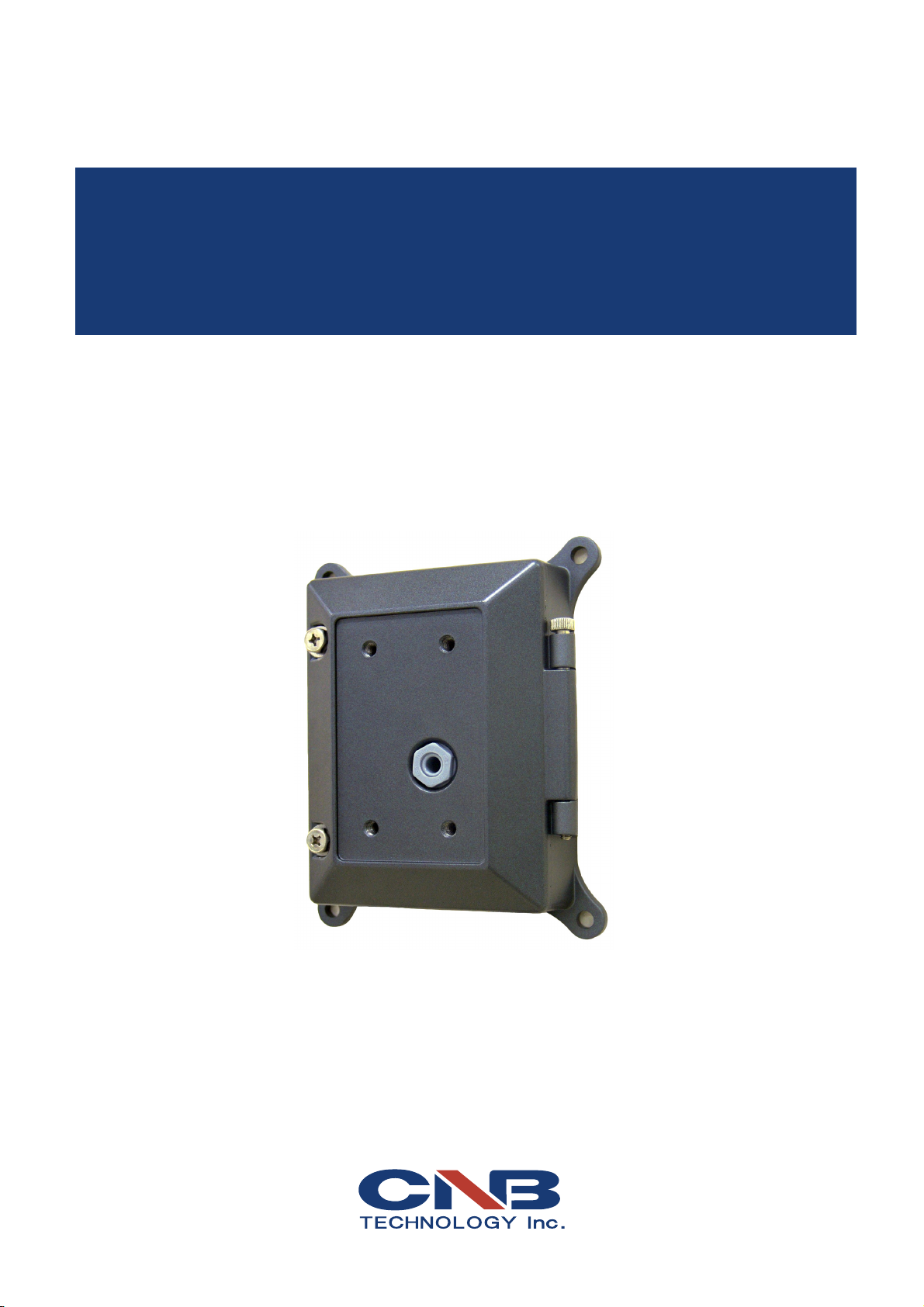
Ver. 1.0
XNET
(IJB2000)
Installation Manual
Page 2

Network Video Server Installation Manual
About this Installation Manual
A compatibility and durability test ensured this product’s high performance.
This installation manual is for XNET Network Video Server users only, and it describes operations
related to XNET Network Video Server.
Please read this manual thoroughly paying attention to cautions and warnings before using the
product even if you have used similar products before.
Important Notices
The copyright of this manual is owned by CNB Technology Inc.
It is illegal to copy and distribute this manual without permission.
Damages caused by use of not suggested parts and misuse will not be applicable for support.
Contact the store or the manufacturer immediately if (you think) there is any problem with the
product.
Contact the store or the manufacturer before disassembling the product for alteration or repair.
XNET is a trademark of CNB Technology Inc.
This product complies for CE (Europe) and FCC (USA) regulations for industrial/home use electrical
device.
INFORMATION
This equipment has been tested and found to comply with the limits for a Class A digital device,
pursuant to Part 15 of the FCC Rules. These limits are designed to provide reasonable protection
against harmful interference when the equipment is operated in a commercial environment. This
equipment generates, uses and can radiate radio frequency energy and, if not installed and used in
accordance with the instruction manual, may cause harmful interference to radio communications.
Operation of this equipment in a residential area is likely to cause harmful interference in which case
the user will be required to correct the interference at his own expense.
2 / 18
Page 3

Network Video Server Installation Manual
Index
1. About XNET ................................................................................................................................................ 4
1.1. About XNET ......................................................................................................................................... 4
1.2. Features of XNET ............................................................................................................................... 4
1.3. Applications .......................................................................................................................................... 4
2. About the Product ................................................................................................................................. 5
2.1. Contents ............................................................................................................................................... 5
2.2 Product Information ............................................................................................................................. 5
2.3. Functions and designations .............................................................................................................. 6
2.3.1. Outer View ................................................................................................................................... 6
2.3.2. Inner View ................................................................................................................................... 6
2.3.3 Connecting to Alarm devices ........................................................................................................ 8
3. Product Installation ................................................................................................................................. 9
3.1. Hardware Installation .......................................................................................................................... 9
3.1.1. Installation ................................................................................................................................... 9
3.1.2. Connecting the Cable ................................................................................................................ 10
3.2. Installing IP-Installer Software and Configuring IP address ....................................................... 12
3.2.1. About IP-Installer ....................................................................................................................... 12
3.2.2. Configuring IP Address .............................................................................................................. 12
4. Using Web Viewer .................................................................................................................................. 14
4.1. Logging In .......................................................................................................................................... 14
4.2. Web Viewer Page ............................................................................................................................. 14
5. Specifications .......................................................................................................................................... 17
3 / 18
Page 4

XNET Network Video Server Installation Manual
1. About XNET
11..11.. AAbboouutt XXNNEETT
XNET is an internet based security and surveillance system that is compatible with various network conditions
through easy installation and user interface as well as multi-functional compressor Codec such as MJPEG,
MPEG-4, and H.264. XNET provides stable real-time surveillance by real time video/ audio at D1 level, local
storage for any network problems, and hybrid IP technology that can be used with existing analog CCTV
devices.
11..22.. FFeeaattuurreess ooff XXNNEETT
z Most advanced Video/ Audio compression technology (MJPEG/MPEG-4/H.264, ADPCM/G726)
z Progressive technology - Progressive scan makes the image sharp and clear without ghost effect.
z Hybrid IP Technology - CCTV analog video output can be used for existing analog CCTV devices.
z Transmission of Multi-Codec stream - Live video signal can be compressed to MJPEG or MPEG-4 (or H.264)
and sent to meet various applications of network or user.
z 2-way Audio Communication (Bi-directional voice communication between Client’s PC and XNET)
z Smart Event feature - On the top of motion detection and sensor/alarm feature, pre- and post- alarm
feature allows automated surveillance without an attendant’s monitoring.
z Install/ Operation Wizard - Install/ Operation Wizard not only makes it easy for installers and users, but
also offers a unified installation setup for massive scale installations.
z Up to 3 motion detection areas
z Motion Detection – Alarm output and Video/ Audio data transmission to FTP site or e-mail upon detecting
a motion.
z Supports Various resolutions - NTSC: 704x480, 352x240 PAL: 704x576, 352x288
z RS-485 interface for Remote Pan/Tilt control
z Remote Control over the network for software upgrade
11..33.. AApppplliiccaattiioonnss
z Surveillance (Building, store, factory, parking lot, financial institutions, government buildings, military
facilities, etc.)
z Remote video monitoring (Hospital, kindergarten, traffic monitoring, remote branch office, weather,
environment preservation, and illegal disposal of trash, etc.)
z Real time broadcasting over the internet (Resort facility, parties, festivals, etc), remote business meetings,
and educational trainings, etc.
4 / 18
Page 5
XNET Network Video Server Installation Manual
2. About the Product
22..11.. CCoonntteennttss
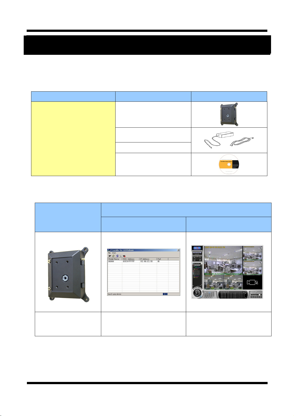
Please make sure the following contents are included when you open the package
22..22.. PPrroodduucctt IInnffoorrmmaattiioonn
Contents Description Additional info.
XNET Product Network Video Server
Power adapter
AC power Cord 3 jack cable
CD Software and User’s manual
Input: 100~240VAC 50-60Hz
Output : 12VDC, 5A
XNET
(IJB2000)
IP-Installer
Install CD
.
Viewer Program
(XNET-NVR)
Network Video Server
(Junction Box)
A software that assigns an IP
address to the product
A software that monitors and
records Audio and Video signal from
the device (supports up to 16
channels)
5 / 18
Page 6
XNET Network Video Server Installation Manual
22..33.. FFuunnccttiioonnss aanndd ddeessiiggnnaattiioonnss
22..33..11.. OOuutteerr VViieeww
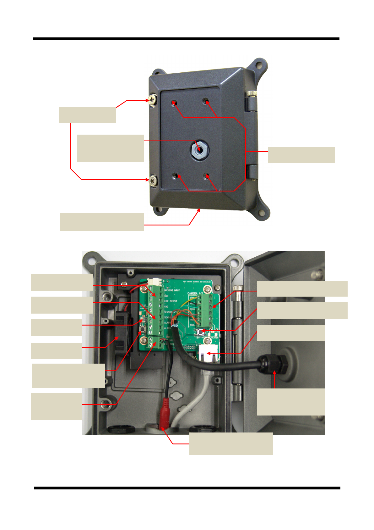
Cover Screw
Camera Cable Feed In
Power/Video/ Control
Cable Feed In
Network/Power/Alarm/Audio
Figure 2-1. IJB2000 Outer
Camera Mount Hole
22..33..22.. IInnnneerr VViieeww
Audio Input/ Output
Alarm Input/ Output
Status LED
FAN
Factory Reset Button
Recalls initial factory settings
Power
Connector
Connection Terminal to Camera
Restart Button
Restarts the network Server.
Network Terminal
Camera Cable Feed In
Power/ Video/ Control
Cable Feed In
Network/ Power/ Alarm/ Audio
Figure 2-2. IJB2000 Inside
6 / 18
Page 7
XNET Network Video Server Installation Manual
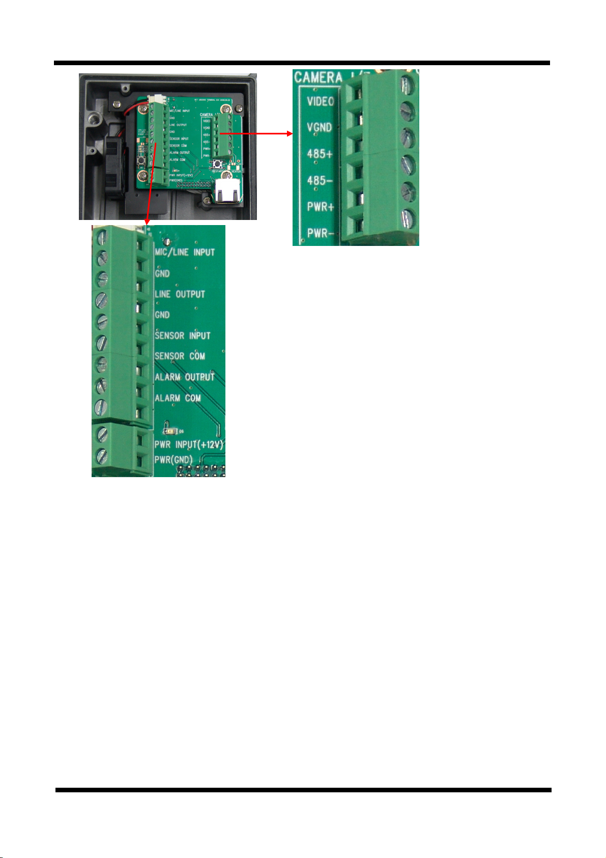
Video In
GND
Control RS485+
Control RS485-
+12VDC
Audio In(Mic/Line)
Audio GND
Audio Out (Line)
GND
Audio GND
Alarm Sensor In +
Alarm Sensor In -
Alarm Out
Alarm Out
+12Vdc
GND
Figure 2-3. Connection Terminal Block
z MIC/LINE IN : Connects to auxiliary Audio Device or microphone.
z LINE OUT : Audio signal output to a Power Amplified device or Speaker. This can be used to listen
to the audio signal sent from a remote PC for Bi-directional Audio communication.
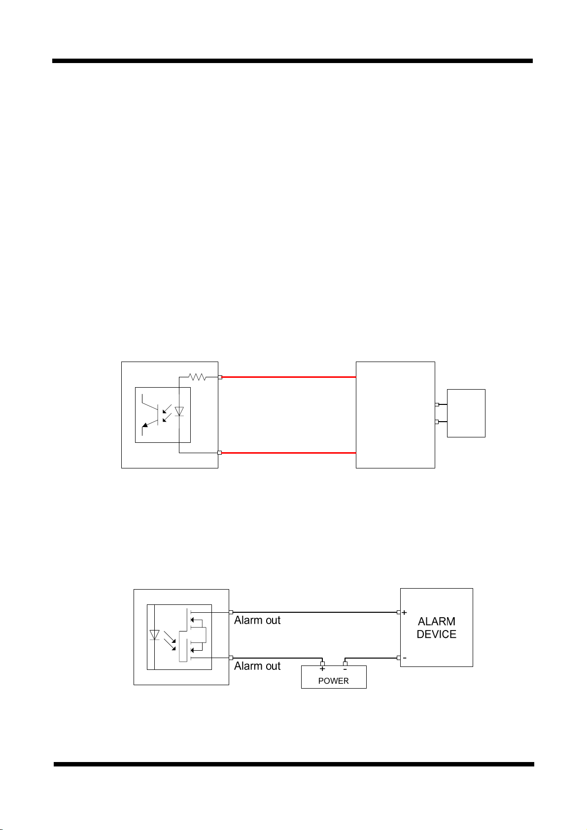
z ALARM IN : This connects to an Alarm Sensor signal. Only one sensor can be connected.
z ALARM OUT : This connects to an external Alarm device that operates by a relay such as Siren
Lamp or Alarm Light. Only one Alarm device can be connected.
z Factory Reset Button: Press and hold for more than 3 seconds while power is on to recall factory
default settings
z Restart Button : Press to restart the network system.
z NETWORK : This Ethernet terminal connects to 10Mbps or 100Mbps LAN through an RJ-45
connector. Status of network connection is displayed in the LEDs on this Terminal.
LINK : Green light indicates that the network is properly connected.
ACT : Yellow light indicates that the XNET system connected to 100Mbps LAN. This green lamp
will blink if the system receives data.
7 / 18
Page 8
XNET Network Video Server Installation Manual
z Power INPUT: Connect 12V DC Power to this terminal.
Please use the power adapter came in the package.
z STATUS LED : Indicates the operation status
- CPU LED : Green light will blink after 50 seconds on power.
- Video Loss LED : Red light indicates that there is no Video Input signal.
- EVENT LED : Green light indicates that Alarm Out signal is turned on.
- POWER LED : Red light indicates that 12V DC power is connected.
22..33..33.. CCoonnnneeccttiinngg ttoo AAllaarrmm ddeevviicceess
z Alarm Input
Wires from various sensor type (IR, heat, and magnetic) can be connected to Alarm in(+)/(-) terminal as
shown in figure 2.5. (NC or NO of sensor input can be selected at Menu screen.)
Alarm Sensor device requires a separate power source.
Signal(+5 ~ 30VDC)
Alarm in(+)
+
Adaptor
-
Photo Coupler
Sensor
Device
GND
Alarm in(-)
Internal Circuitry External Circuitry
Figure 2-4. Connecting to Alarm Input
z Alarm Output
This terminal can only be connected up to DC 30V/400mA. An additional relay device has to be used to
control higher voltage or current.
Internal Circuitry External Circuitry
Figure 2-5. Connecting to Alarm Output
8 / 18
Page 9
XNET Network Video Server Installation Manual
3. Product Installation
This section provides brief guidelines to install the XNET quickly and to monitor XNET’s Video and Audio
signals easily. If you have questions about details not explained in this section or if the product is not
functioning as described, please refer to FAQ before contacting the store.
Our homepage is
33..11.. HHaarrddwwaarree IInnssttaallllaattiioonn
33..11..11.. IInnssttaallllaattiioonn
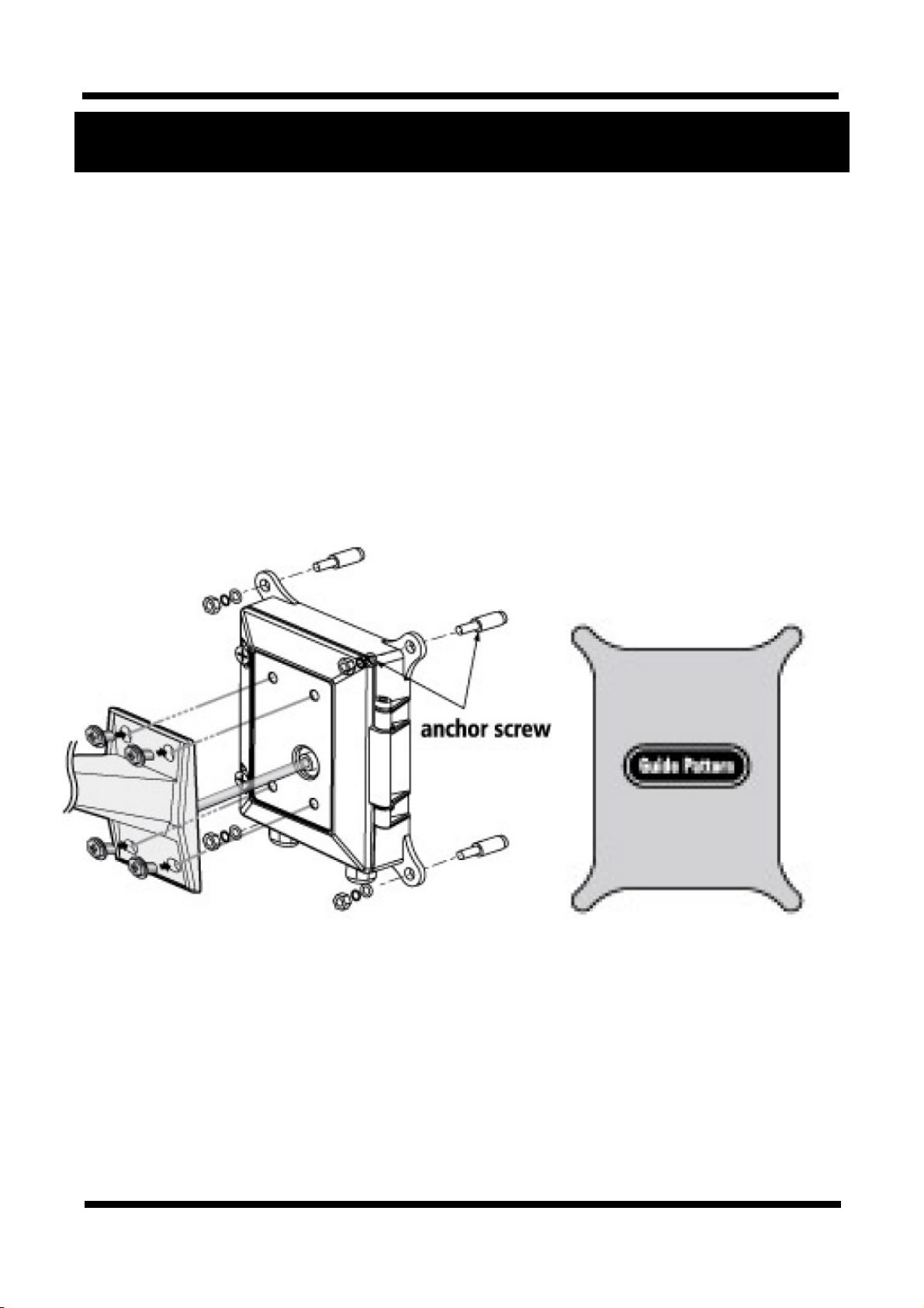
As shown in the picture, drill 4 screw holes using the guide pattern provided. Insert Anchor screws to the
holes and fix the Video Server using screws. Make sure the wall is firm enough to hold the camera and the
video server (junction box).
http://www.cnbtec.com
.
Guide Pattern
Insert the camera’s cable into the feeding hole on the front cover of the junction box, and then mount the
camera to the server using the screws.
9 / 18
Page 10
XNET Network Video Server Installation Manual
33..11..22.. CCoonnnneeccttiinngg tthhee CCaabbllee
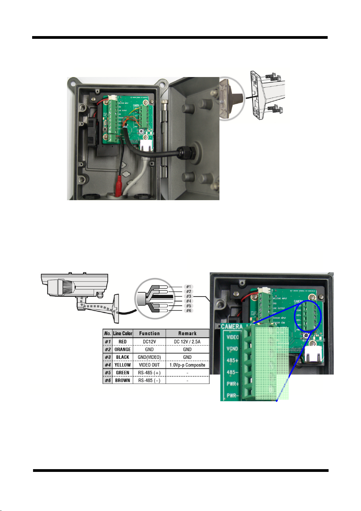
1. Connect the wires according to the detail shown in the table below.
(Cut wires if necessary.)
YELLOW
BLACK
GREEN
BROWN
RED
ORANGE
This Junction box is designed to be used with specific cameras. Please contact CNB dealer to ask
about purchasing
10 / 18
Page 11
XNET Network Video Server Installation Manual
2. A PC or a laptop computer is required to set up an IP address.
z Compatible operating system: Windows 2000/ Windows XP/ Windows Vista
z Since the default IP address of the device is 192.168.123.100, set up the IP address of the
computer like the following:
IP Address : 192.168.123.101 Subnet Mask : 255.255.255.0
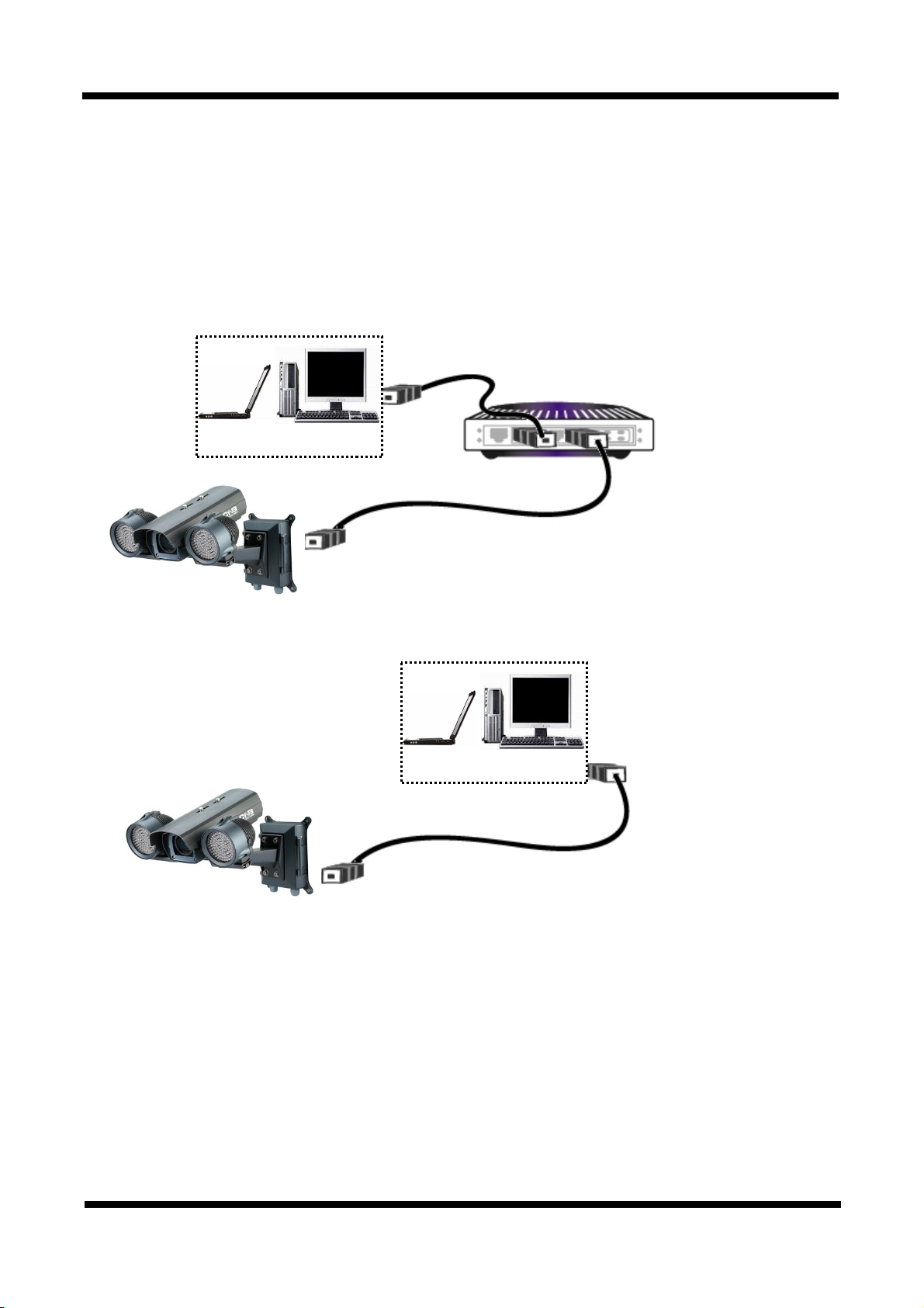
3. Connect LAN cable to the Network Terminal of the product.( Use a crossover cable when
connecting it directly to a PC, and use a direct cable when connecting it to a HUB)
NETWORK HUB
COMPUTER
Direct Network
Cable
COMPUTER
Crossover
Network Cable
Figure 3-1. Network Connection
4. Connect the device to the power.
5. Use the Alarm Sensor/ output and audio terminal if necessary.
11 / 18
Page 12
XNET Network Video Server Installation Manual
33..22.. IInnssttaalllliinngg IIPP--IInnssttaalllleerr SSooffttwwaarree aanndd CCoonnffiigguurriinngg IIPP aaddddrreessss
33..22..11.. AAbboouutt IIPP--IInnssttaalllleerr
A unique IP address has to be configured in order to connect network device and monitoring PC to a network.
IP-Installer software provided in the Installation CD (included in the package and also available to download
from our website http://www.cnbtec.com
server that automatically assigns IP addresses to network devices. If your network does not have a DHCP
server, the default IP address of the device is 192.168.123.100. Refer to IP Installer user’s manual for detail.
33..22..22.. CCoonnffiigguurriinngg IIPP AAddddrreessss
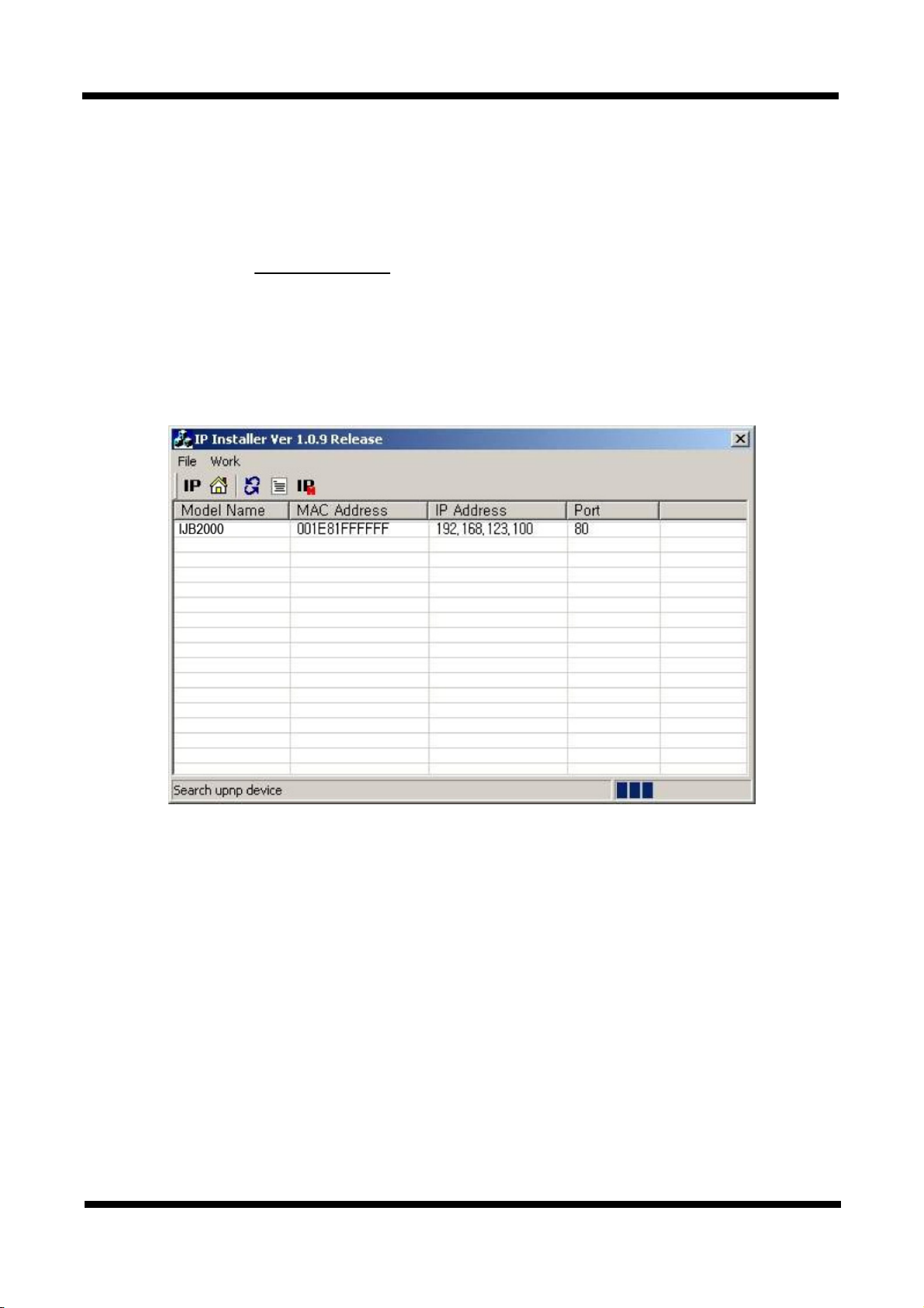
1. The following box will appear when you start the IP-installer software.
) will configure IP address easily. If your network have a DHCP
Figure 3-2. IP Installer Start box
12 / 18
Page 13
XNET Network Video Server Installation Manual
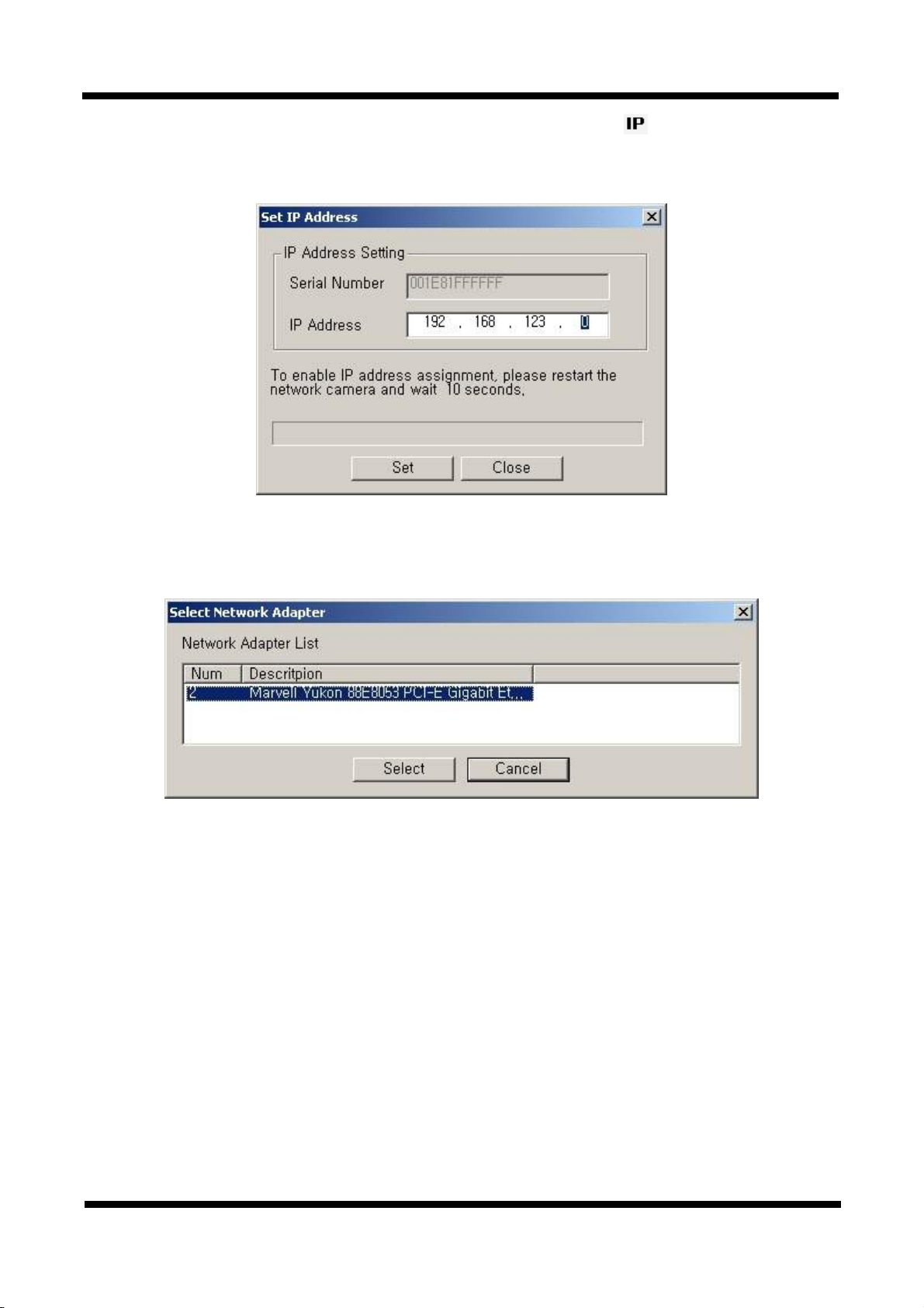
2. Select the device of which you wish to change the IP address and click
button to bring up the following box in Figure 3-3.
Figure 3-3. IP Address box
3. When you enter the IP address and click Set button, the box shown in Figure 3-4 will appear.
(Set IP Address)
Figure 3-4. Select Network Adapter Box
4. Select the adapter and click select button to change the IP address of the device.
13 / 18
Page 14
XNET Network Video Server Installation Manual
[
4. Using Web Viewer
Connecting to network devices can be done using internet web browser or “XNET-CMS” software. This
manual explains about using internet web browser only. For instructions on how to configure network
connection using XNET-CMS software, please refer to XNET-CMS Manual, which can be found in the
installation CD.
44..11.. LLooggggiinngg IInn
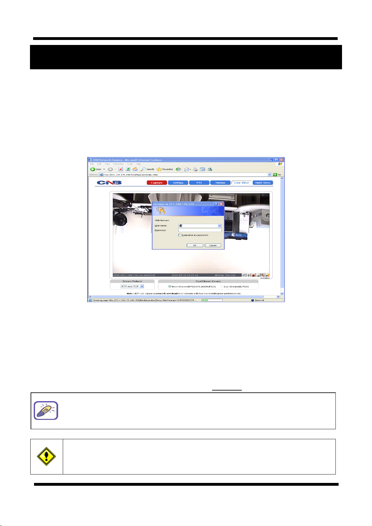
Enter the IP address of the device on the address bar of your web browser and press enter key. Then the
following webpage will appear:
Figure 4-1. Log-in Box
Enter the user name and password to bring up the web viewer page. The default id and password is
“root”, “ admin” respectively. If you want to use a different HTTP port number from the default value,
simply put a colon and port number at the end of the IP address. (For example, enter the following
address when changing the port to 8080: http://192.168.123.100:8080)
<Address format for accessing as an administrator>
(When using default IP address and port number)
(When IP address and port number changed)
For security, please change the administrator’s id and password from their default
values. Please save the changed ID and password in a place only accessible by an
administrator. Please refer to
If you forget the administrator’s password, “Factory Reset” is the only way to regain
access. However, since this will retrieve all default settings, the network settings
have to be configured again using the IP installer.
Web Viewer Manual] for detail.
http://192.168.123.100
http://IP address: new port number
14 / 18
Page 15
XNET Network Video Server Installation Manual
44..22.. WWeebb VViieewweerr PPaaggee
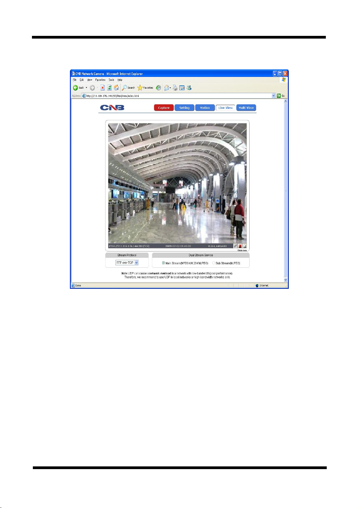
Web viewer page consists of Video monitor screen and menu option buttons.
Figure 4-2. Web Viewer Page
15 / 18
Page 16
XNET Network Video Server Installation Manual
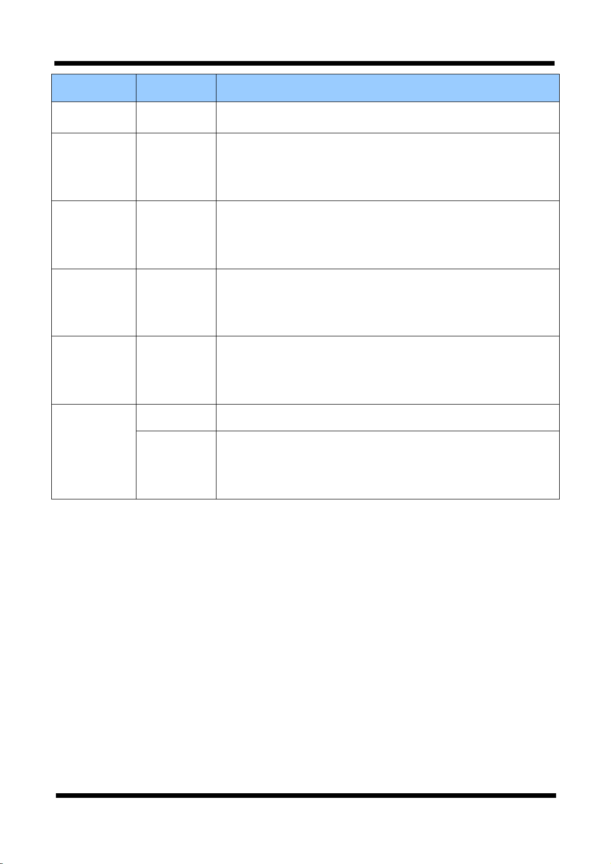
Item Sub Item Description
Capture -
Setting -
PTZ -
Motion -
Multi View -
Captures and saves the current image as a still picture.
The image is saved as jpeg file in the following folder: C:₩xNetCapture
Brings up Menu screen.
Setup page for each XNET feature can be opened from this Menu screen.
Please refer to [XNET Owner’s Manual] for detail.
Opens up PTZ page.
This page can set up control of PTZ movement.
Please refer to [XNET Owner’s Manual] for detail.
Opens up Motion Detection page.
You can add or delete areas for detecting motion in this page.
Please refer to [XNET Owner’s Manual] for detail.
Opens up Multi View page.
You can view videos from cameras that are programmed in Multi Video
Player setup page. Please refer to [XNET Owner’s Manual] for
detail.
Live View
Main Stream When this box is checked, Main Stream Video is displayed.
When this box is checked, Sub Stream Video is displayed.
Dual-Codec needs to be enabled in Video Setup Page in order for Sub
Sub Stream
Stream to be displayed.
Please refer to [XNET Owner’s Manual] for detail.
16 / 18
Page 17
XNET Network Video Server Installation Manual
5. Specifications
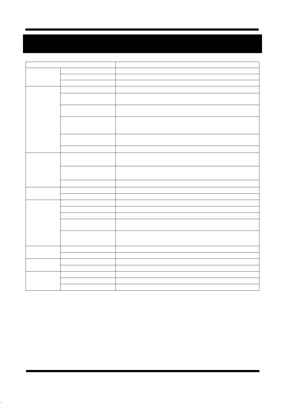
IJB2000 Specifications
Video Signal
Video / Audio
Network
Security
Alarm and Event
Management
Applications
Maintenance
Mechanical
Input Signal
Signal Select
Compatible Camera Model
Compression MJPEG / MPEG4 / H.264
Frame rate
Resolution
Video streaming
Image settings
Audio Two-way (full duplex / ADPCM, G.726)
Protocol
Supported DDNS
LAN Interface Ethernet 10/100 Base-T (RJ-45 Type)
Access level setup Multiple user access levels with password protection
Network Security IP Filtering
Image detection Motion detection (Select 3 Regions - each area)
Sensor detection Sensor In, Scheduling, Alarm out
After Event process JPEG Image upload over FTP server / SMTP (E-mail server)
Local storage
Pre / Post alarm
Browser Internet Explorer 6.0 over
Monitoring Application XNET NVR, CNB CMS and Utility (IP-Installer, etc), 3rd party SW
System Upgrade Firmware upgrade over HTTP
PTZ control (RS-485) PTZ Protocol Service (User define update)
Operating Temperature -10℃ ~ 50℃
Power DC 12V Max. 5 W
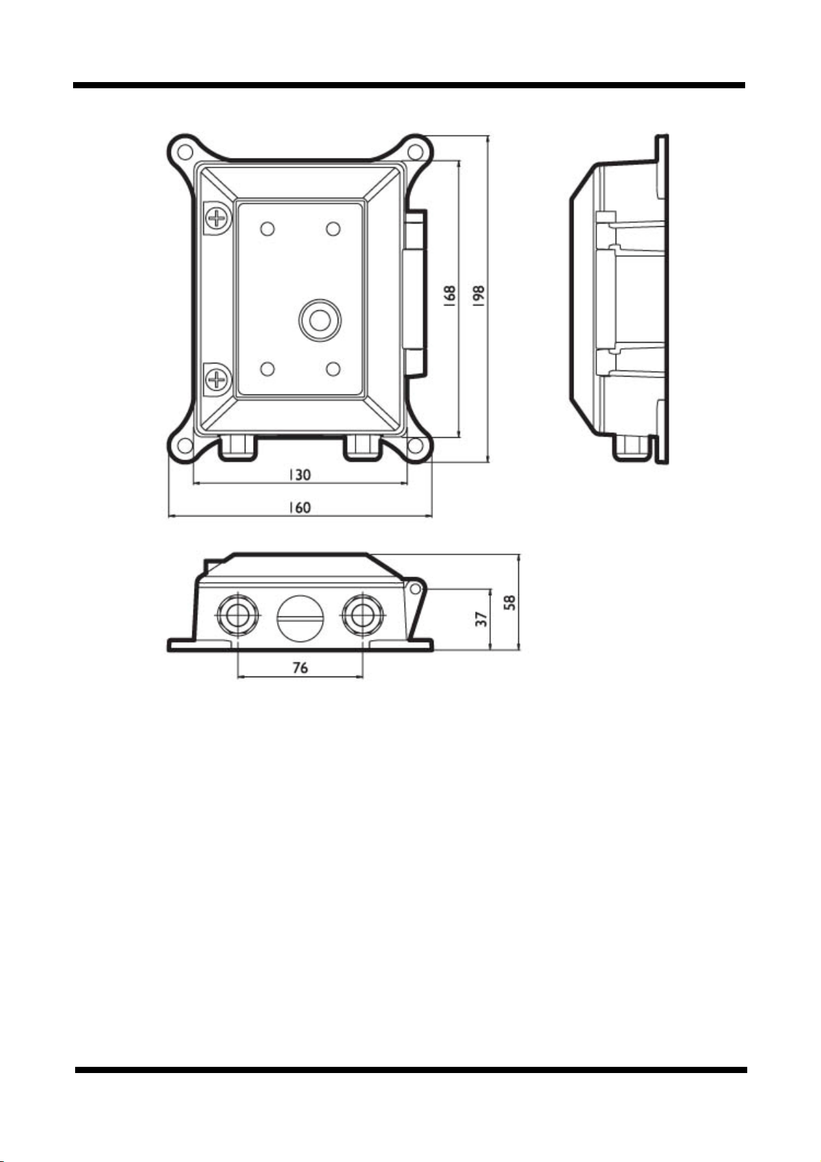
Dimensions 198(D) x 160(W) x 58(H)mm
1ch Input Composite by B3, B4, B5, B6 Series
NTSC/PAL (Manual)
B3 / B4 / B5 / B6 Series all models
Single Mode : Main(H.264@30fps) *D1
Dual Mode : Main(H.264/MPEG4, 30fps), Second(MPJEG) *D1
D1 (NTSC: 704 x 480 / PAL: 704 x 576)
CIF (NTSC : 352 x 240 / PAL: 352 x 288)
MJPEG / H.264(or MPEG4) Dual mode
Constant and variable bit rate in MPEG4 (128kbps ~ 3M bps)
Controllable frame rate and bandwidth
Compression level setting
Configurable Brightness, Sharpness, White Balance
Ipv4, HTTP, HTTPs, UDP, TCP, RTSP, RTP, SMTP, FTP, ICMP, DHCP, UPnP, Bonjour,
ARP, DNS, DynDNS, NTP, IGMP(Multicast) *) OnVif
1. CNB DDNS 2. DynDNS.org
3. Reference code with SDK
JPEG Image write to Internal memory
- Internal memory : Max 32MByte
Detail time-set : Max Pre alarm 5 sec / Post alarm 8 sec
Local storage (Internal memory : JPEG image)
17 / 18
Page 18
XNET Network Video Server Installation Manual
18 / 18
 Loading...