

Page 1
Ver. 1.0
XNET
(IGP1000F)
User Manual
Page 2

XNET User Manual
About this Manual
A compatibility and durability test ensures this product’s high performance.
This manual is for XNET Network product users only, and it describes operations related
to XNET Network products.
Please read this manual thoroughly paying attention to cautions and warnings before
using the product even if you have used similar products before.
Important Notices
The copyright of this manual is owned by CNB Technology Inc.
It is illegal to copy and distribute this manual without permission.
Damages caused by misuse and by use of parts not recommended
will not be applicable for support.
Contact the store or the manufacturer immediately if (you think)
there is any problem with the product.
Contact the store or the manufacturer before disassembling the
product for alteration or repair.
XNET is a trademark of CNB Technology Inc.
z This product complies for CE (Europe) and FCC (USA) regulations
for industrial/home-use electrical device.
2 / 53
Page 3

XNET User Manual
Index
1. System Administration .................................................................................................... 4
1.1. Logging On ............................................................................................................................. 4
1.1.1. Using Internet Explorer ............................................................................................................... 4
1.1.2. ID and Password ......................................................................................................................... 4
1.2. Configuring Camera ............................................................................................................... 6
1.3. Web Viewer (Index.html) ........................................................................................................ 8
1.4. Status Window ...................................................................................................................... 10
1.5. Configuring Users ................................................................................................................. 11
1.6. Setting Date &Time .............................................................................................................. 13
1.7. Configuring Multi-Viewer ...................................................................................................... 15
1.8. Configuring PTZ ................................................................................................................... 17
1.9. Maintaining Server Configurations ....................................................................................... 19
1.10. Generating Log Report ....................................................................................................... 21
1.11. Configuring Audio ............................................................................................................... 23
1.12. Configuring Video ............................................................................................................... 25
1.13. Configuring RTP/RTSP ...................................................................................................... 27
1.14. Configuring Camera Condition ........................................................................................... 29
1.15. Configuring the Network(TCP/IP) parameters .................................................................... 31
1.16. Configuring IP Filtering ....................................................................................................... 33
1.17. Configuring HTTP ............................................................................................................... 35
1.18. Configuring UPnP/DynDNS/Bonjour .................................................................................. 37
1.19. Configuring CMS ................................................................................................................ 39
1.20. Configuring Event Type ...................................................................................................... 40
1.21. Configuring Sensor/Alarm .................................................................................................. 42
1.22. SMTP Setup ....................................................................................................................... 44
1.23. Configuring FTP ................................................................................................................. 46
1.24. Configuring and operating Digital PTZ ............................................................................... 48
1.25. Configuring and operating PTZ .......................................................................................... 49
1.26. Configuring Motion Detection area ..................................................................................... 51
1.27. Configuring Multi View Option ............................................................................................ 53
3 / 53
Page 4

XNET User Manual
1. System Administration
11..11.. LLooggggiinngg OOnn
You can log on as an administrator using either Internet browser or ‘CMS’ software. (This manual will describe
about using Internet browser only.)
11..11..11.. UUssiinngg IInntteerrnneett EExxpplloorreerr
Type the IP Address of the XNET product in the address bar and press enter.
e.g.) : http://192.168.123.100
If the HTTP port has been changed from the default value, enter the new port as shown below:
IP Address of the XNET: Port No.
e.g.) : http://192.168.123.100:8080
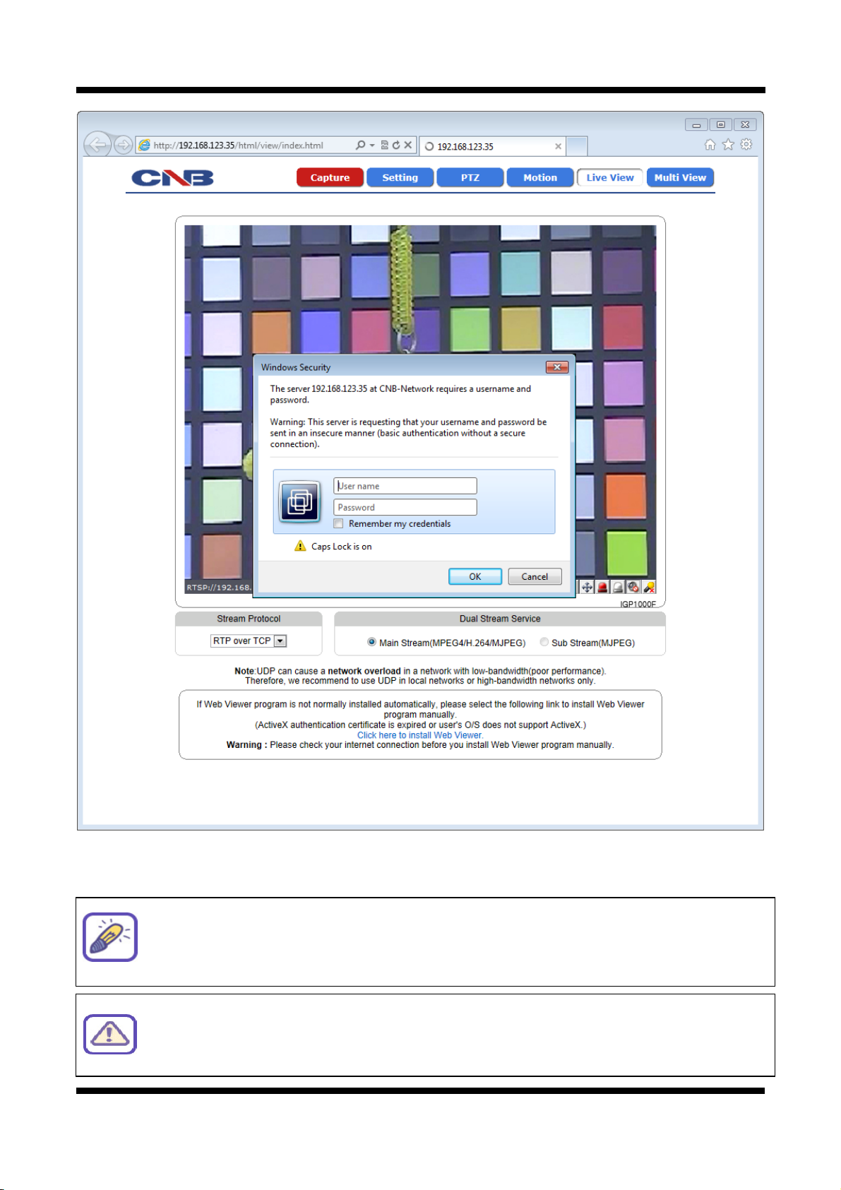
11..11..22.. IIDD aanndd PPaasssswwoorrdd
If you are logging in as an administrator, the Log-In box will appear as shown in figure 1-1. Basic Setup page
will appear when you enter id and password.
4 / 53
Page 5
XNET User Manual
g
Figure 1-1 Log-in window
The default user name and password is “root” and “admin” respectively.
For security purpose, it is recommended to change the administrator’s id and
password from their default values. Please be careful not to forget them or expose
them to others. Please refer to [1.5] for detail.
If you forget the administrator’s password, “Factory Reset” is the only way to regain
access. However, since this will retrieve all default settings, you need to configure the
network settin
s using IP installer software again.
5 / 53
Page 6
XNET User Manual
11..22.. CCoonnffiigguurriinngg CCaammeerraa
When you log in as an administrator, XNET’s Basic Setup page will appear as shown in Figure 1-2. Setup
pages for different features can be accessed from this page. Access to each feature are controlled by different
Figure 1-2 Basic Setup Page
6 / 53
Page 7

XNET User Manual
Basic Setup Page can be accessed from Operator group level and up. If you want to access Administrator
level page in this user level, you need to log in as Administrator. Please refer to the following table for
access authority:
● Accessible
▬ Not Accessible
Function
Access
Administrator Operator Viewer
Index Page ● ● ●
Multi-Index Page ● ● ●
PTZ Page ● ●
Motion Page ● ●
Users
Setup Page
Date&Time
Setup Page
Multi-Viewer
Setup Page
Maintain Server
Setup Page
System / Log
Setup Page
Audio
Setup Page
Video
Setup Page
Camera Condition
Setup Page
TCP / IP
Setup Page
IP Filtering
Setup Page
SMTP
Setup Page
FTP
Setup Page
HTTP
Setup Page
UPnP / DynDNS
Setup Page
RTP
Setup Page
CMS
Setup Page
●
● ●
●
●
●
● ●
● ●
● ●
●
●
●
●
●
●
●
●
▬ ▬
▬ ▬
▬ ▬
▬ ▬
▬ ▬
▬ ▬
▬ ▬
▬ ▬
▬ ▬
▬ ▬
▬ ▬
▬ ▬
▬
▬
▬
▬
▬
▬
Event Type
Setup Page
Sensor/Alarm
Setup Page
PTZ Configuration
Setup Page
● ●
● ●
● ●
▬
▬
▬
7 / 53
Page 8
XNET User Manual
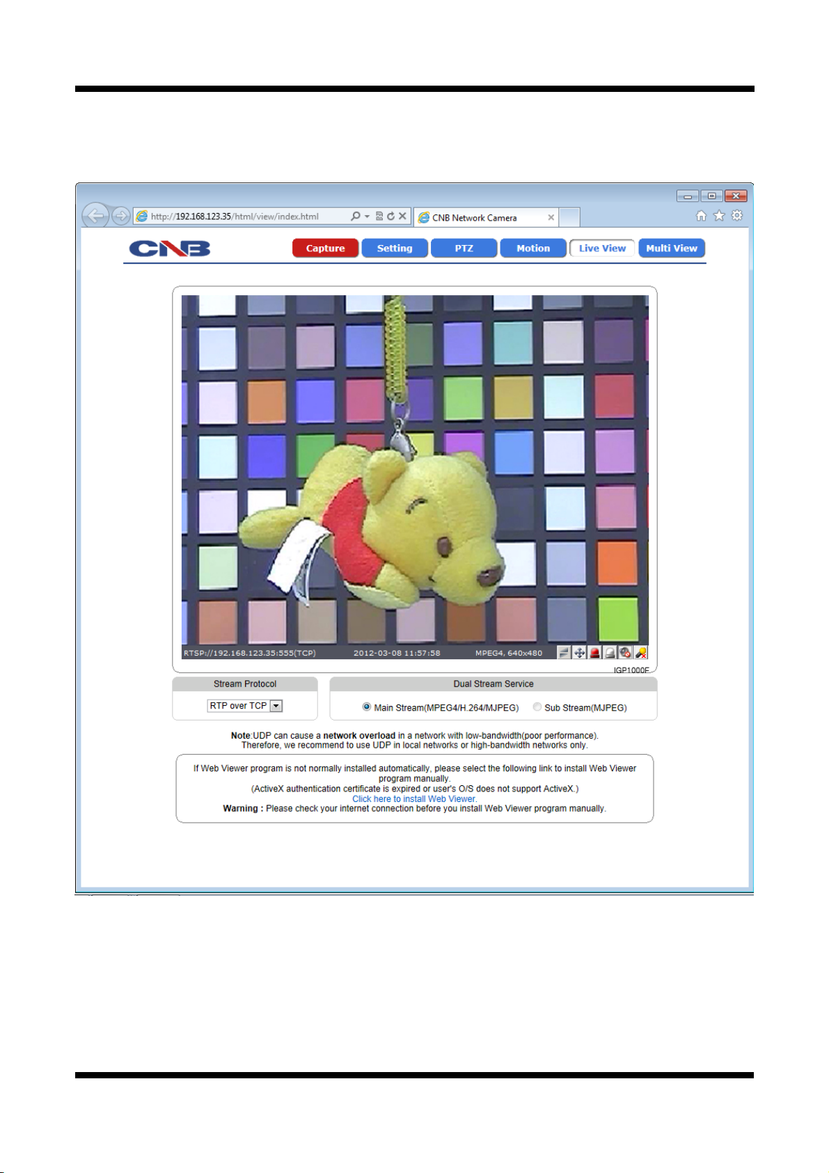
11..33.. WWeebb VViieewweerr ((IInnddeexx..hhttmmll))
When you access an XNET product, Web Viewer page will appear automatically. Viewer area displays the
video output from the camera, and menu bar contains taps that lead to each feature setting page.
Figure 1-3 Web Viewer Page
8 / 53
Page 9

XNET User Manual
ITEM
Capture -
Captures the still image and displays on a pop-up window.
[Save to] c:₩xNetCapture
Opens up Basic Setup Page.
Setting -
Setup page for each XNET feature can be opened from this Menu
screen.
(Please refer to 1.4 for detail)
Opens up PTZ page.
This page can set up digital PTZ of the network camera and control
PTZ -
of PTZ movement. (Please refer to 1.8 for detail)
Support Model : IGP1030 / INS2000 / IJB2000
Opens up Motion Detection page.
Motion -
You can add or delete areas for detecting motion in this page.
(Please refer to 1.27 for detail)
Opens up Index View page.
Live View -
Index View Page will display Video as well as setting up Stream
Protocol ( TCP / UDP ) and Codec (when using Dual Stream).
DESCRIPTION
Multi View -
Stream Protocol -
Main Stream
Dual Stream
Service
Sub Stream
Opens up Multi View page.
Multi View page will display up to 4 video signals set up in IGP1030’s
Multi Video Player Setup Page.
(Please refer to 1.7 for detail)
A Stream Protocol can be selected when selecting EditBox
(RTP over TCP/RTP over UDP)
When this box is checked, Main Stream Video is displayed.
(MPEG4/H.264/MJPEG)
When this box is checked, Sub Stream Video is displayed.
Dual-Codec needs to be enabled in Video Setup Page in order for
Sub Stream Video to be displayed. (MJPEG)
(Please refer to 1.12 for detail)
9 / 53
Page 10
XNET User Manual
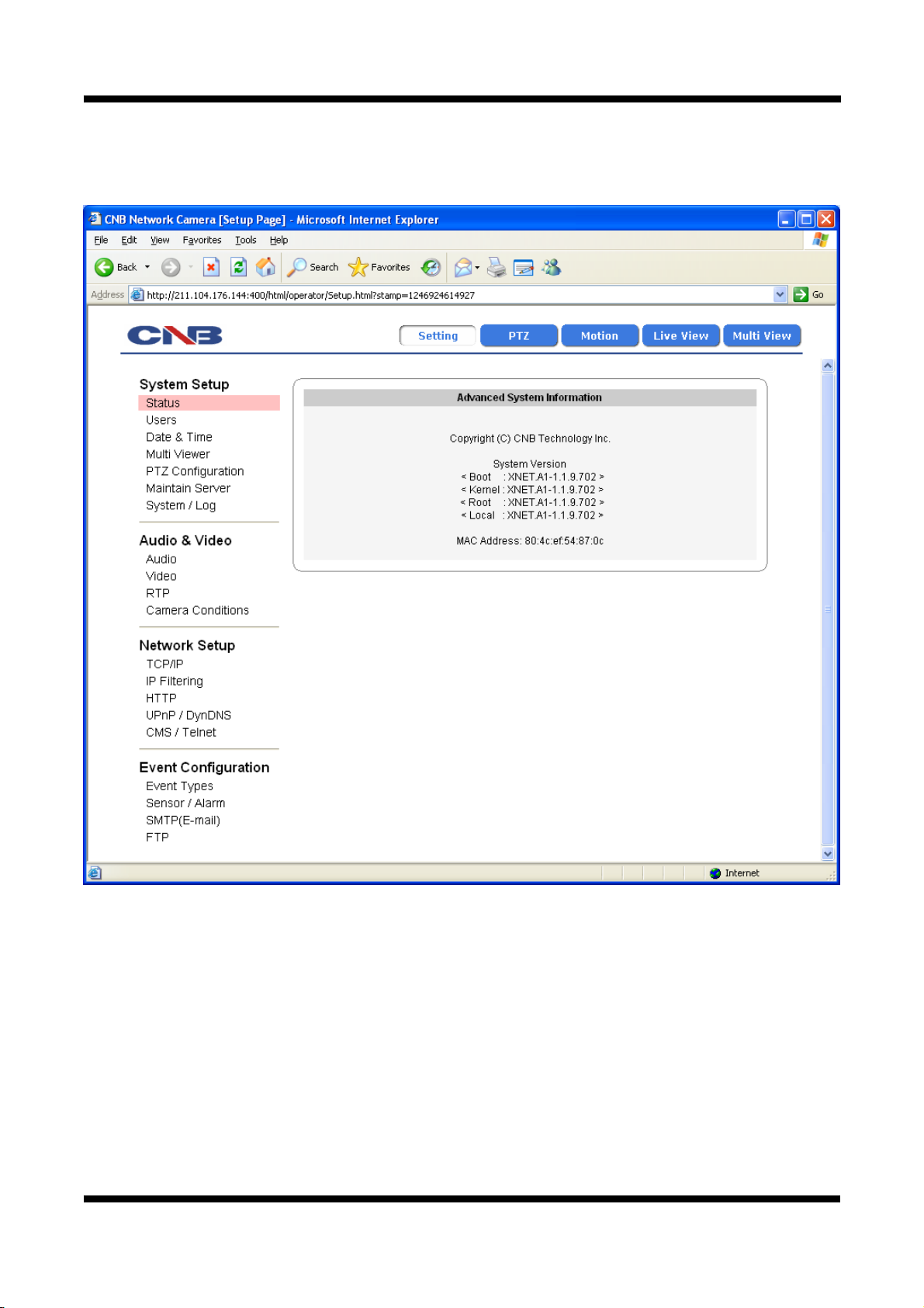
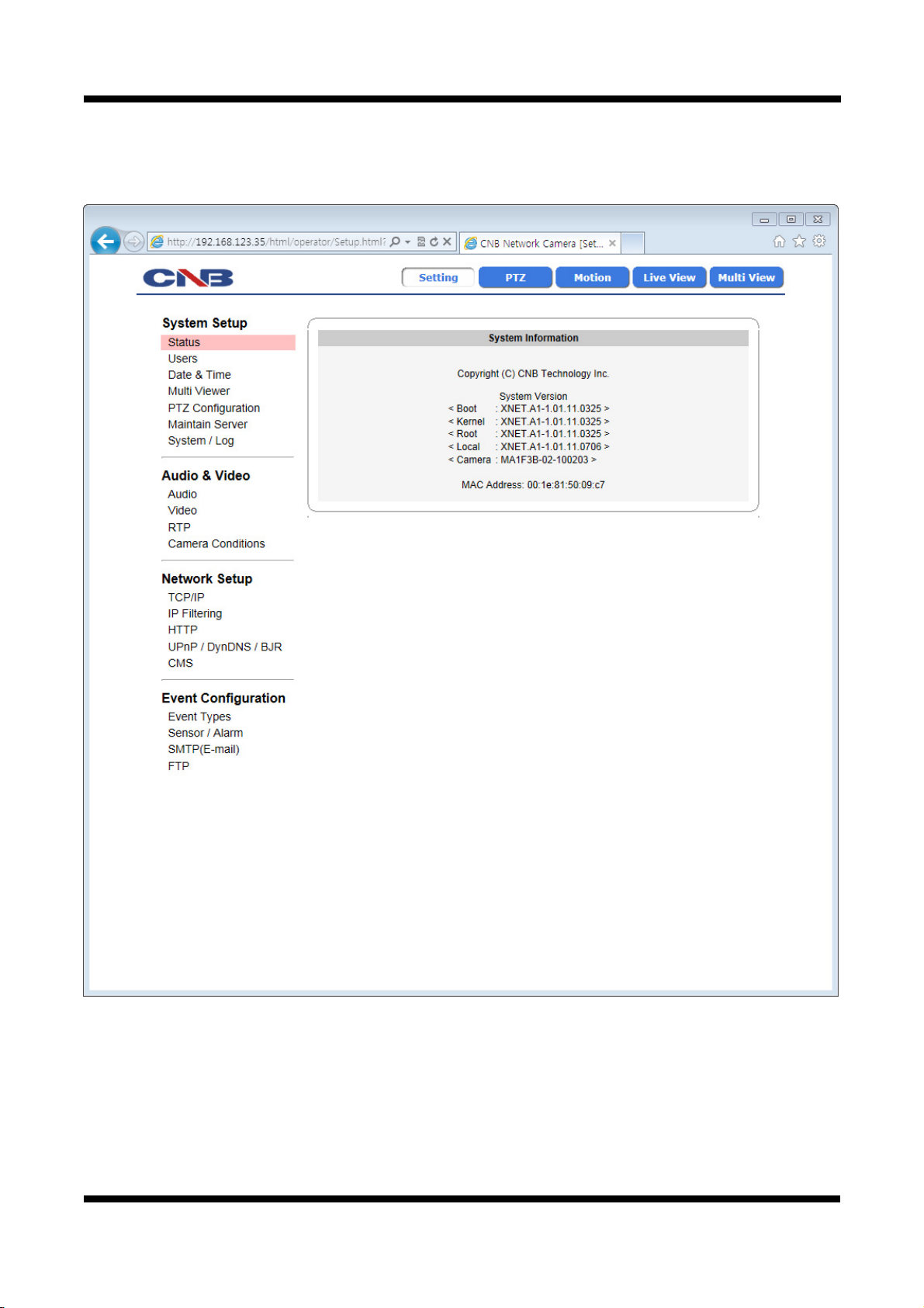
11..44.. SSttaattuuss WWiinnddooww
Status page displays XNET System’s Version and its Ethernet address.
Click [▷ Status] button to open the page shown in Figure 1-4.
Figure 1-4 Status Page (Internet Explorer 7.0)
10 / 53
Page 11
XNET User Manual
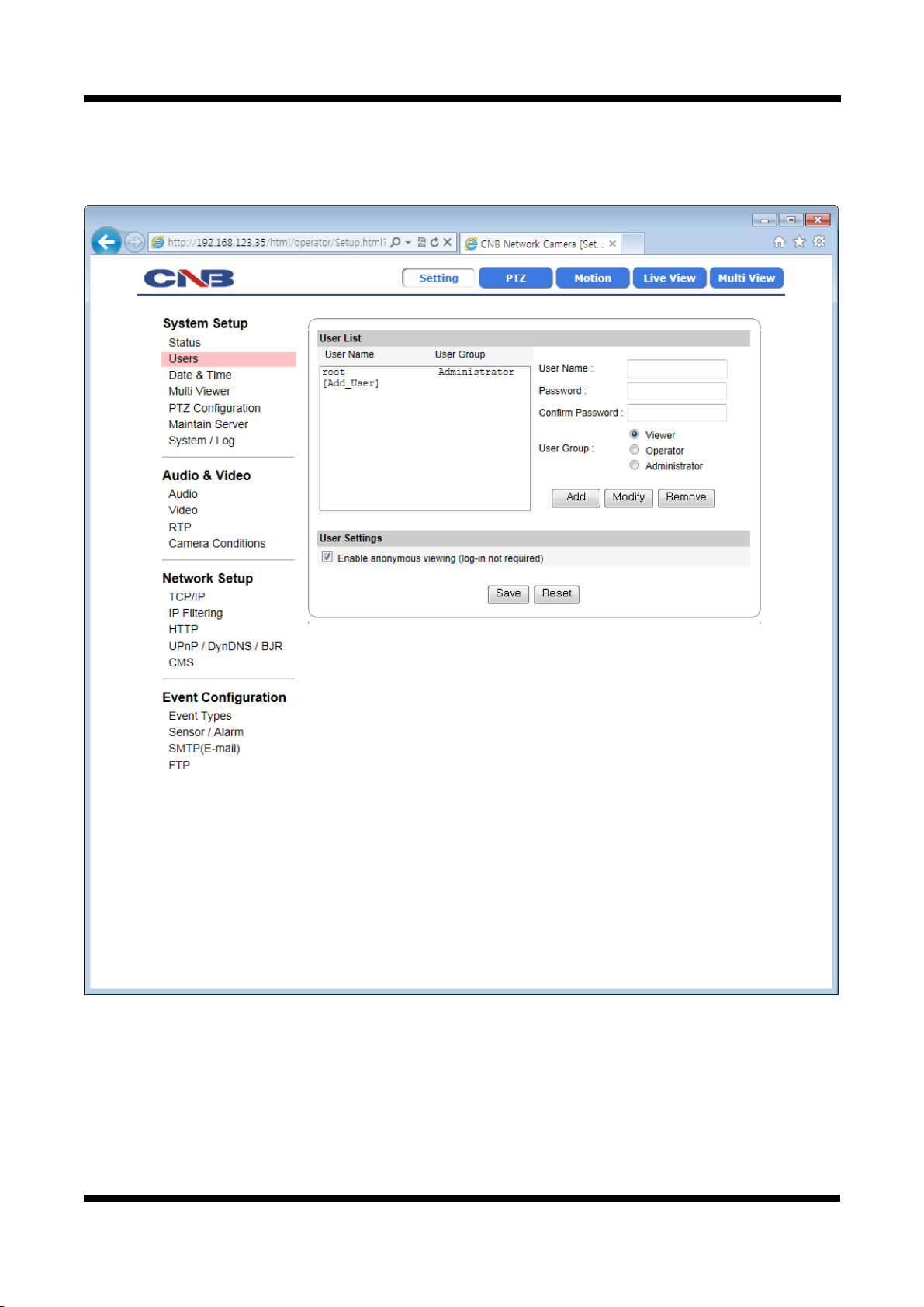
11..55.. CCoonnffiigguurriinngg UUsseerrss
This can give or limit authority to users for controlling Video and other features of XNET system.
Click [ ▷ Users] button to open the page shown in Figure 1-5.
Figure 1-5 Users Configuration Page
11 / 53
Page 12

XNET User Manual
ITEM
User List
Add -
Modify -
DESCRIPTION
Displays list of registered users.
"root" is the system’s administrator. "root" cannot be added or deleted.
Only the password for “root” can be changed.
This adds a new user.
Select “[Add_User]” tap in User List Box. To add a new user, enter
User name, Password, and User group then click Add button.
Updated User list can be viewed in User List Box.
- Up to 10 users can be added.
- Authority of different User Groups
Administrator : Full control of the XNET system.
Operator : Control over Viewer, Audio&Video Setup, and Event
Configuration.
Viewer : view camera’s video signal only.
Modifies information for each user.
Select a user in User Listbox, enter new Password/ User Group, and
click modify button to save the changes.
Updated detail can be viewed in User List Box.
Removes a user.
Remove -
Select a user in User Listbox and click remove button to remove.
Updated user list can be viewed in User List Box.
Enable
User Settings
anonymous
viewer
Turns Anonymous Viewer mode on or off.
When enabled, Web Viewer can be accessed without a log-in prompt.
login
Save -
Applies and saves the configurations
Reset - Recalls previously saved configurations.
12 / 53
Page 13
XNET User Manual
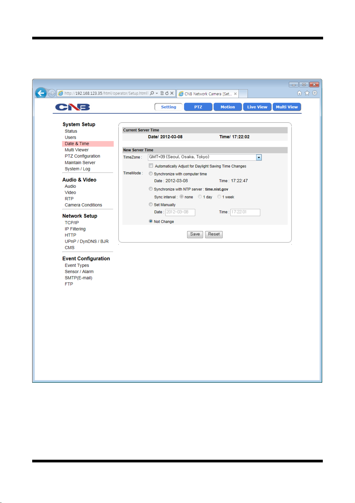
11..66.. SSeettttiinngg DDaattee &&TTiimmee
This page will change Date and Time of XNET system.
Click [ ▷ Date & Time] to open the page shown in Figure 1-6.
Figure 1-6 Date and Time Page
13 / 53
Page 14

XNET User Manual
ITEM
DESCRIPTION
Current Server Time - Displays time of XNET system.
Time Zone Selects Time Zone. <Default : GMT+09>
Enable
Daylight
Enables/ Disables Daylight Saving time.
Time
Sets Date and Time of the Server.
<Default : None>
New Server Time
[Synchronize with computer time]
- Synchronizes time and date of Client PC to Server.
Time Mode
[Synchronize with NTP server]
- Synchronizes server’s time and date to NTP Server.
(Enter NTP Server address in Network Setup Page)
[Set Manually]
- Set date and time of Server manually.
Save - Applies and saves the configurations
Reset - Recalls previously saved configurations.
14 / 53
Page 15
XNET User Manual
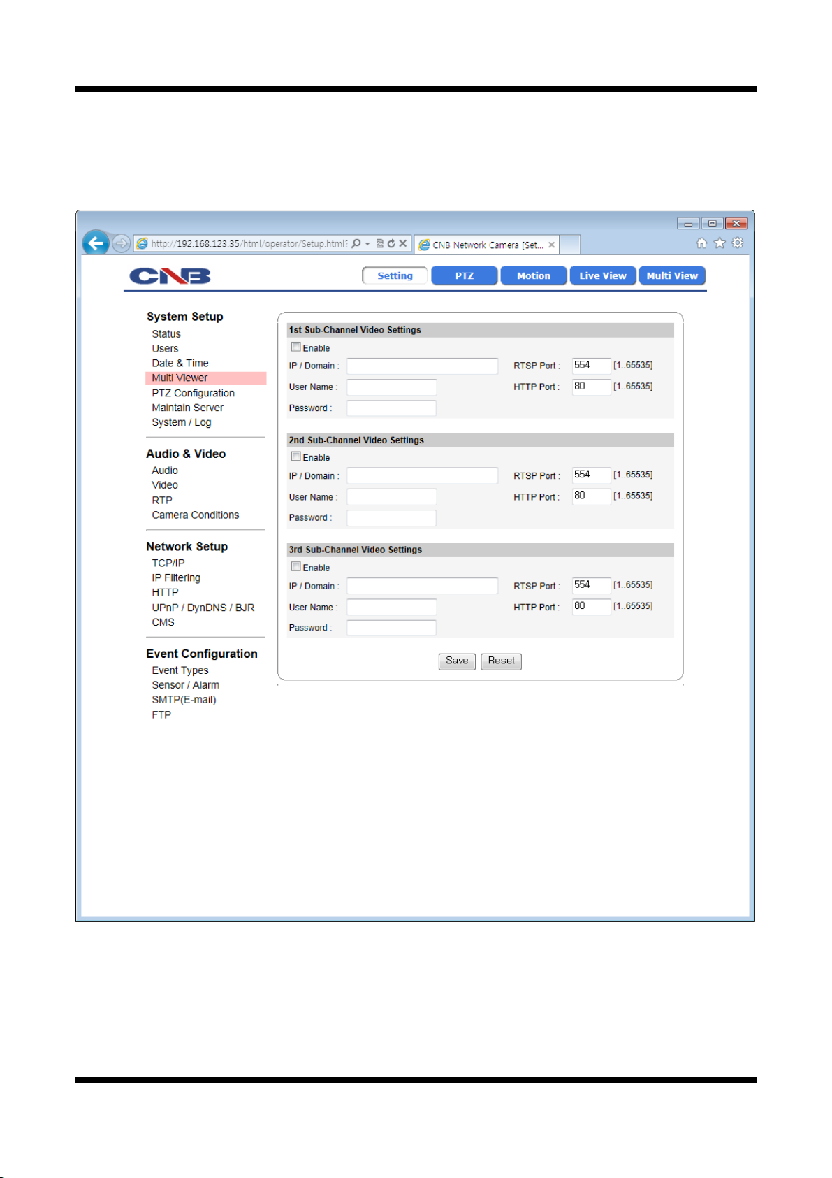
11..77.. CCoonnffiigguurriinngg MMuullttii--VViieewweerr
Up to 3 cameras connected to XNET’s network can be displayed as sub-cameras simultaneously in Multi-View
page.
Click [ ▷ Multi Viewer] to open the page shown in Figure 1-7.
Figure 1-7 Multi-Viewer Configuration Page
15 / 53
Page 16

XNET User Manual
ITEM
1st Sub-
Channel Video
Settings
2nd Sub-
Channel Video
Settings
3rd Sub-
Channel Video
Settings
DESCRIPTION
Enable 1st
Sub Channel
Video
Enables viewing of 1st sub Channel Video from the IP address
entered. This can only be enabled when IP Address, User Name, and
Password is properly entered.
<Default : Disable>
1st IP Address Enter 1st Channel’s IP Address
1st User name Enter 1st Channel’s User name
1st Password Enter 1st Channel’s Password.
Enables viewing of 2nd sub Channel Video from the IP address
entered. This can only be enabled when IP Address, User Name, and
Enable 2nd Sub
Channel Video
Password is properly entered.
<Default : Disable>
<Default : Disable>
2nd IP Address Enter 2nd Channel’s IP Address
2nd User name Enter 2nd Channel’s User Name
2nd Password Enter 2nd Channel’s Password
Enables viewing of 3rd sub Channel Video from the IP address
Enable 3rd
Sub Channel
Video
entered. This can only be enabled when IP Address, User Name,
and Password is properly entered.
<Default : Disable>
<Default : Disable>
3rd IP Address Enter 3rd Channel’s IP Address
3rd User name Enter 3rd Channel’s User Name
3rd Password Enter 3rd Channel’s Password
Save - Applies and Saves the configurations
Reset - Recalls previously saved configurations.
16 / 53
Page 17

XNET User Manual
11..88.. CCoonnffiigguurriinngg PPTTZZ
This configures XNET’s PTZ server information,
Click [ ▷ PTZ Configuration] to open the page shown in Figure 1-8.
Figure 1-8 PTZ Configuration page
17 / 53
Page 18

XNET User Manual
ITEM DESCRIPTION
PTZ Protocol
Upload
-
Uploads a Protocol to be used by the PTZ.
The uploaded file can be viewed in PTZ Protocol List.
Configures PTZ Protocol.
Set
PTZ Protocol
List
Del
Select Protocol File from PTZ Protocol List and click Set button to
activate the protocol.
Deletes PTZ Protocol File.
Select Protocol File from PTZ Protocol List and click Del button to
delete the selected protocol.
Camera ID Establishes Camera ID of the PTZ.
PTZ Setup
Pan Speed Establishes Pan Speed of the PTZ.
Tilt Speed Establishes tilt speed of the PTZ.
Save - Applies and saves changes.
Reset - Recalls previously saved configurations.
18 / 53
Page 19

XNET User Manual
11..99.. MMaaiinnttaaiinniinngg SSeerrvveerr CCoonnffiigguurraattiioonnss
This page configures system parameters such as system restart, factory default settings, system upgrade,
saving configurations, saving images, and other additional features.
Click [ ▷ Maintain Server] to open the page shown in Figure 1-9.
Figure 1-9 Server Maintenance Page
19 / 53
Page 20

XNET User Manual
ITEM DESCRIPTION
Restart Restarts the system. It takes about 45 seconds.
Maintain
Server
Image/Camera
Initialization
System
Upgrade
BackUp Backup
Reset Image Deletes all Alarm Images from the internal Flash Memory.
Reset Camera Initializes the Camera’s Condition parameters.
Restore
Default
Reset Log Deletes all Log Messages.
Upgrade
Resets all parameters except for TCP/IP settings.
This restore will be followed by a 45 seconds system reset.
Resets all parameters to Facory Default setting.
This will be followed by a 45 seconds system restart.
Use this to upgrade the system.
Select location of Upgrage file in Client PC and click Upgrade button.
This will be followed by one-minute system restart.
(Note) Please do not disconnect power and LAN cable from the XNET
while the upgrade is in process. It might cause a system error.
Upgrade File can be downloaded from http://www.cnbtec.com
This saves current configurations in Client PC.
Back up file can be restored to other XNET cameras.
This will be followed by a 45 seconds system reset.
This loads up settings from a saved Backup file.
Click restore button after selecting backup files in Client PC. Optional
check boxes can be used to select settings to be excluded from the
restore process.
- except TCP/IP box: Exlcude TCP/IP settings.
Restore Restore
Save Image Save Image
- except Users box: Exclude Users settings.
- except IP Filter box: Exclude IP Filter settings.
- except Camera Condition box
: Exclude Camera Condition settings.
This will be followed by a one-minute system reset.
Saves alarm images in the Internal Memory to Client PC. Click
SaveImage button to pop up FTP Connection page. XNET’s FTP
server can be accessed by logging in as "root" with its password.
20 / 53
Page 21

XNET User Manual
11..1100.. GGeenneerraattiinngg LLoogg RReeppoorrtt
Log report contains detailed information about XNET’s image, setup, and error.
Click [ ▷ Log Report] button to open the page shown in Figure 1-10.
Figure 1-10 Log Report Page
21 / 53
Page 22

XNET User Manual
System
Settings
Log Report
ITEM
DESCRIPTION
System
Overview
Displays current configurations for XNet option pages.
Loads up Log Message file stored in the xNet product.
Load List
Log Message file can be sorted with date and index.
Click Load List button to view message list in the Listbox.
Logs View Select a file from the Log List and click Logs view button to view.
Logs Del Select a f ile from the Log List and click Delete button to delete.
Save Logs
Select a file from the Log List and click Save Logs button to save the
file to PC.
22 / 53
Page 23

XNET User Manual
11..1111.. CCoonnffiigguurriinngg AAuuddiioo
Xnet’s Audio features can be configured in this page.
Click [ ▷ Audio] button to open the page shown in Figure 1-11.
Figure 1-11 Audio configuration Page
23 / 53
Page 24

XNET User Manual
ITEM DESCRIPTION
Audio
Enable
Audio
Input
Enable audio
Source
Enables or Disables Audio feature
<Default : Disable>
Select audio input source between Microphone and line.
<Default : Microphone>
Microphone input can be used when users send their voice over XNET
system.
Line input takes the input from an audio device to send over XNET.
Audio sent to XNET can be played at a Client’s PC or an audio device.
Encoding
Selects audio input Encoding method. <Default : G726>
G726 and PCM can be selected.
Save - Applies and saves changes.
Reset - Recalls previously saved configurations.
24 / 53
Page 25

XNET User Manual
11..1122.. CCoonnffiigguurriinngg VViiddeeoo
XNET’s Video features can be configured in this page.
Click [ ▷ Video] button to open the page shown in Figure 1-12.
Figure 1-12 Video Configuration Page
25 / 53
Page 26

XNET User Manual
Main Stream
Frame Rate
Control
ITEM
Resolution
Dual-Codec
Frame rate
RTCP Callback
Codec
Enable
Control
DESCRIPTION
Select a resolution of the video image.
Selectable resolutions differ by models like the following:
IGP1030 : CIF | VGA | XGA | SXGA <Default : VGA>
IDP4000/IVP4000 : CIF | VGA <Default : VGA>
IDP4030/IVP4030 : CIF | VGA | XGA | SXGA <Default : VGA>
INS2000/IJB2000 : CIF | D1 <Default : D1>
Selects Video Codec. XGA/SXGA selected in IGP1030/IDP4030
/IVP4030 will operate as MJPEG, but other cameras can choose
among MJPEG, MPEG4, and H.264.
Turns Sub Stream feature on or off. <Default : Disable>
Sub Stream output is in MJPEG with maximum 15 frame per second.
When configuring, select Main Stream or Sub-Stream in the Index
page.
“Enable Dual-Codec checkbox” is enabled when Codec is set up as
MPEG4 or H.264.
Selects Frame rate of Video output.
IGP1030/IDP4030/IVP4030 : 1~24 Frame
IDP4000/IVP4000/INS2000/IJB2000 : 1~30 Frame
If this checkbox is selected, the value of the ‘Frame rate' above is
automatically adjusted in case overload occurs by sharing lack
bandwidth with bit transmission(the ‘Rate bit’ value on the ‘MPEG4 &
H.264 Appearance’ item).
Actual transfer rate may be lower than the selected
Frame rate above if this checkbox is selected.
MJPEG
Appearance
Quality Select MJPEG’s video quality between 10 and 100.
Selects bit rate for MPEG4 or H.264 video signal between 128kbps and
3Mbps.
MPEG4 &
H.264
Appearance
Bit rate
It is recommended to select this bitrate in consider of
the chosen number of the 'Maximum numbers of users
to connect' item on the RTP setting page because the
value resulted from multiplying this bitrate by that
number should not exceed 10.
Sub Stream Resolution Select resolution of sub stream video among CIF | VGA | D1.
Frame Rate
Control
MJPEG
Appearance
Frame rate
Quality Select sub stream video quality between 10 and 100.
Select Frame rate of sub stream video between 1 ans 15 frames per
second.
Save - Applies and saves changes.
Reset - Recalls previously saved configurations.
26 / 53
Page 27

XNET User Manual
11..1133.. CCoonnffiigguurriinngg RRTTPP//RRTTSSPP
This is related to XNET’s DDNS server information.
Click [ ▷ RTP/RTSP] to open the page shown in Figure 1-13.
Figure 1-13 RTP/RTSP Page
27 / 53
Page 28

XNET User Manual
ITEM DESCRIPTION
Enter RTSP Port of the Main Stream between 1 and 65535.
The default is 554.
Enter RTSP Port of the Sub Stream between 1 and 65535. The
default is 665.
Enter RTP Start Port between 1024 and 65534.
The default is 2000.
Enter RTP End Port between 1124 and 65535.
The default is 3000.
Enter the maximum allowable number of users connected to the
Stream between 1 and 10.
It is recommended to select this number in consider of
the chosen bitrate of the 'Bit rate' item on the Video
setting page because the value resulted from
RTSP
Configuration
RTP
Configuration
RTSP Port
Multiple-RTSP
Port
RTP Start Port
RTP End Port
Maximum
number of users
to connect
multiplying this number by that bitrate should not
exceed 10.
Save - Applies and saves changes.
Reset - Recalls previously saved configurations.
28 / 53
Page 29

XNET User Manual
11..1144.. CCoonnffiigguurriinngg CCaammeerraa CCoonnddiittiioonn
This is related to camera features of the XNET products.
Click Reset Camera Figure button in System Setup Menu₩Main Server₩ to initialize the Camera during its
operation.
Click [ ▷ Camera Condition] button to open the page shown in Figure 1-14.
Figure 1-14 Camera Conditions Page
29 / 53
Page 30

XNET User Manual
ITEM DESCRIPTION
Video Output
Format
White Balance
Video Format
Enable Video
Output
Selects Video format at Video Out terminal between
NTSC and PAL.<Default : Disable>
Turns the Video Out feature on or off.
<Note: IGP1030, IxP4030 outputs video in VGA level or less. >
Configures Video’s White Balance.
White Balance means balancing color temperature by adjusting Red
White Balance
and Blue level.
Auto mode will adjust White Balance automatically, while manual
mode will adjust white balance level according to manually configured
Red and Blue level.
Select Video’s Red level between brightness of 0 and 255.
Red Control
This can only be enabled when White Balance is configured as Manual
mode.
Select Video’s Blue level between brightness of 0 and 255.
Blue Control
This can only be enabled when White Balance is configured as Manual
mode.
Push Push will adjust White Balance automatically in manual mode
Read Displays current configurations for Red and Blue level.
Brightness Select Brightness of Video between 5 and 255.
Saturation Select Color Saturation of Video between 0 and 7.
Video Setting
Gain &
Shutter
Condition
Sharpness Select Sharpness of Video between contrast 0 and 7.
DC-IRIS Lens
Back Light
Compensation
Select lens type for IGP1030. IGP1030 accepts 2 types of lenses
(DC-IRIS/MANUAL).
Turns Back Light Compensation on or off.
When enabled, the images will not be saturated even when too much
light comes into the Lens.
Color/Mono Selects between Color/Mono of the Video.
Day/Night Selects between Auto/Day/Night for IR LED.
Configures Exposure of Video.
Exposure means to control brightness of video by adjusting Gain
Exposure
value.
In auto mode, Exposure will automatically be adjusted to proper level
according to its selected Indoor or Outdoor type. In Manual mode,
Exposure will be adjusted to the gain value entered.
Gain Control
Select Gain level of Video between
0 – 7 only in Manual Exposure mode.
Configures Camera’s Shutter Speed.
High Shutter Speed can capture a quick movement accurately, but
Video gets noisy while it tries to maintain brightness level properly.
Shutter Speed
Control
Low Shutter Speed reduces Video Noise, but it will not catch quick
movement very well. In Manual mode, shutter speed will be
configured value. In Auto mode, shutter speed will be changed
automatically from highest value to configured value.
In Auto mode, we recommend configuring the lowest value.
Save - Applies and Saves the configurations.
Reset - Recalls previously saved configurations.
30 / 53
Page 31

XNET User Manual
11..1155.. CCoonnffiigguurriinngg tthhee NNeettwwoorrkk((TTCCPP//IIPP)) ppaarraammeetteerrss
This configures XNET’s network related parameters.
Click [ ▷ TCP/IP] button to open the page shown in Figure 1-15.
Figure 1-15 Network Setup Page
31 / 53
Page 32

XNET User Manual
ITEM DESCRIPTION
Enable DHCP
Turns DHCP on or off.
Check DHCP checkbox to get an IP address automatically from the
network using DHCP protocol. Obtained IP address can be viewed by
IP Installer.
(Note) If the network does not use DHCP server, the product will wait
for server’s response for two minutes and restart with its previous IP
address.
IPv4 Address
Configuration
DNS
Configuration
NTP
Configuration
Host name
Configuration
Enter an IP address.
IP address
Configure IP address after checking IP address range configuration of
the router where the XNET product is connected.
Enter Subnet mask.
Subnet mask
Use this when you want to access only from the same subnet by
masking out upper portion of the IP address.
Use 255.255.255.255 when you want to connect from one PC only.
Default router Enter the address of Default router.
Domain name Enter Domain name.
Primary
DNS Server
Secondary DNS
Server
Network
address
User
the host name
Enter primary DNS address.
Enter secondary DNS address.
Enter address of NTP (Network Time Protocol Server.)
NTP server is used when “Synchronize to NTP Server” is selected in
Date&Time page.
Enter Host name
Ethernet
Address
Ethernet
address
Enter Ethernet Address.
Save - Applies and saves changes.
Reset - Recalls previously saved configurations.
32 / 53
Page 33

XNET User Manual
11..1166.. CCoonnffiigguurriinngg IIPP FFiilltteerriinngg
This configures IP Filters for XNET product.
Click [ ▷ IP Filtering] button to open the page shown in Figure 1-16.
Figure 1-16 IP Filtering Page
33 / 53
Page 34

XNET User Manual
ITEM DESCRIPTION
Filter IP
Addresses
Add -
Remove -
- Displays list of currently established IP Filters.
Adds an IP address to filter out.
Enter the IP Address to block and click add button to add it to IP
Filtering listbox.
The updated list can be viewed in IP Address Listbox.
- Up to 20 IP addresses can be added.
Removes an IP address from IP Filtering listbox.
Select the IP address to remove and click Remove button to remove it
from the list.
The updated list can be viewed in IP Address Listbox.
IP Filter
Enable
Enable
IP
Filtering
Turns the IP Filter on or off.
When turned on, XNET product will not be accessed from the IP
addresses in IP Filtering Listbox.
Save - Applies and saves changes.
Reset - Recalls previously saved configurations.
34 / 53
Page 35

XNET User Manual
11..1177.. CCoonnffiigguurriinngg HHTTTTPP
This configures HTTP port to access XNET’s webpage.
Click [ ▷ HTTP] button to open the page shown in Figure 1-17.
Figure 1-17 HTTP Page
35 / 53
Page 36

XNET User Manual
ITEM
DESCRIPTION
Enter HTTP Port to access the webpage.
HTTP
HTTP
port
Default port is 80, and any other port number has to be entered at
the end of the ip address when accessing. (e.g. When using HTTP
Port 8080, enter http://192.168.123.100:8080)
Save - Applies and saves changes.
Reset - Recalls previously saved configurations.
36 / 53
Page 37

XNET User Manual
11..1188.. CCoonnffiigguurriinngg UUPPnnPP//DDyynnDDNNSS//BBoonnjjoouurr
UPnP is a protocol for IP installer software. You can enable or disable this UPnP, and you can also use a
Friendly Name.
DynDNS configures XNET’s DDNS server information.
Click [ ▷ UPnP/DynDNS] to open the page shown in Figure 1-18.
Figure 1-18 UPnP/DynDNS Page
37 / 53
Page 38

XNET User Manual
ITEM
UpnP
Setting
Enable UPnP
Enables or disables UPnP.
When enabled, you can use IP Installer’s XNET Auto Search feature.
Friendly Name Enter UPnP’s Friendly Name.
Enables or disables DynDNS.
Enable DynDNS
When enabled, you can automatically obtain a domain from DDNS
server by simply registering the XNET product.
Enables or disables DynDNS Anonymous feature. When enabled,
DDNS service is used without going through authentication at
Autoipset.com DDNS server.
DynDNS
Setting
Enable
Anonymous
Alias Host Name Enter a Host Name for the DynDNS server.
User Name Enter a user Name for the DynDNS server.
Password Enter a password for the DynDNS server.
Bonjour
Setting
Enable Bonjour
Enables or disables Bonjour.
When enabled, you can use IP Installer’s XNET Auto Search feature.
Server Name Enter Bonjour’s Server Name.
Save - Applies and saves changes.
DESCRIPTION
Reset - Recalls previously saved configurations.
38 / 53
Page 39

XNET User Manual
11..1199.. CCoonnffiigguurriinngg CCMMSS
This configures XNET’s CMS Server information.
Click [ ▷ CMS] to open the page shown in Figure 1-19.
Figure 1-19 CMS Page
ITEM
CMS CMS port
Save - Applies and saves changes.
Reset - Recalls previously saved configurations.
Enter CMS port number for communication with CMS between 1 and
65535. The default is 5000.
DESCRIPTION
39 / 53
Page 40

XNET User Manual
11..2200.. CCoonnffiigguurriinngg EEvveenntt TTyyppee
This is related to XNET’s DDNS Server information.
Click [ ▷ Event Types] to view page shown in Figure 1-20.
Figure 1-20 Event Types Page
40 / 53
Page 41

XNET User Manual
ITEM
Event Enable Enable Event
Sensor Enables or disables the Alarm sensor.
Event Mode
Motion
Detection
Capture Frame
Pre-Alarm
Event Setting
Post-Alarm
Event Schedules
Event
Schedules
DESCRIPTION
Enables or disables event processing. <Default : Disable>
<Note for IGP1030 users>
When this is enabled in the SXGA Mode, the transmitted fame rate is
reduced by up to 10 fps.
When this is enabled in the XGA Mode, the transmitted fame rate is
reduced by up to 6 fps.
Enables or disables Motion Detection.
When processing an event, this establishes the number of images to
be saved per second. It can be selected between 1 and 3.
When processing an event, this establishes saving images before the
occurance of the event.
It can be between 1 and 5 seconds before the event, and the number
of the images to be saved gets determined by the Capture Frame rate.
When processing an event, this establishes saving images after the
occurance of the event.
It can be between 1 and 8 seconds after the event, and the number of
the images to be saved gets determined by the Capture Frame rate.
Enables or disables scheduled event monitoring.
When Always is selected while Event (Alarm) is activated, the unit will
monitor event (Alarm.) all the time.
During Time is selected while Event (Alarm) is activated, the unit will
monitor event (Alarm.) during the time period specified.
Event Schedules
Setting
Specifiy schedule for Event (Alarm) monitoring. Event (Alarm) is
monitored according to the schedule specified here.
This allows Alarm images to be uploaded to an FTP server when
Upload image to
FTP
processing an event. The client PC has to run FTP server to receive the
images, and the information of the FTP server has to be accurately
entered and saved at the FTP Cofiguration page.
Event
Output
Alarm Output
Port
This sends out Alarm signal to its output port during event processing.
This allows Alarm images to be sent out by an e-mail when processing
Send Image to
Email
an event. Only one image file at the moment of the event gets sent
out. The e-mail address has to be accurately entered and saved at
SMTP configuration page.
This allows Alarm images to be saved in the internal memory. Saved
image can get transferred to the client’s PC by using save image
button at system configuration page.
This allows Alarm images to be saved in the external memory (SD
Card). SD card has to be properly installed and recognized for this
feature.
Select
Storage
Save Image to
Internal Memory
Save Image to
SD Memory
Save - Applies and saves changes.
Reset - Recalls previously saved configurations.
41 / 53
Page 42

XNET User Manual
11..2211.. CCoonnffiigguurriinngg SSeennssoorr//AAllaarrmm
This is related to XNET’s DDNS server information.
Click [ ▷ Sensor / Alarm] to open the page shown in Figure 1-21.
Figure 1-21 Sensor / Alarm Page
42 / 53
Page 43

XNET User Manual
DESCRIPTION
Sensor
Setting
Alarm
Setting
ITEM
Signal Type
Out Interval
Selects the signal type for Alarm Input Port between Normally Close
and Normally Open.
Configures interval between repeating Alarm Out signals between
1 and 3 seconds.
Save - Applies and saves changes.
Reset - Recalls previously saved configurations.
43 / 53
Page 44

XNET User Manual
11..2222.. SSMMTTPP SSeettuupp
This configures mailing out method of Alarm Images once ‘event’ occurred in the XNET system.
Click [ ▷ SMTP] button to open the page shown in Figure 1-22.
Figure 1-22 SMTP Page
44 / 53
Page 45

XNET User Manual
ITEM DESCRIPTION
Enable
Internal SMTP
Server
Turns Internal SMTP Server on or off.
When this box is checked, Alarm Image gets mailed out through an
internal mail server. Mail Authentication cannot be used in this mode.
When this box is unchecked, Alarm Image gets mailed out through an
external mail server. Mail Authentication, port, user, password, mail
address, etc. needs to be configured.
SMTP
Settings
Enable
SMTP
Authorization
SMTP Server
Name
Enables or disables the use of SMTP authorization when using external
mail server.
Enter the name of external mail server.
SMTP Port Enter the port number for the external mail server.
User name Enter the user name of the external mail server.
Password Enter the password of the external mail server user.
E-mail
Address
Setting
Email
Address
Enter the e-mail address of the external mail server user.
Save - Applies and saves changes.
Reset - Recalls previously saved configurations.
45 / 53
Page 46

XNET User Manual
11..2233.. CCoonnffiigguurriinngg FFTTPP
This configures how the Alarm Images get sent out using FTP once ‘event’ occurred in the XNET system.
Click [ ▷ FTP] button to open the page shown in Figure 1-23.
Figure 1-23 FTP Page
46 / 53
Page 47

XNET User Manual
ITEM DESCRIPTION
FTP
Server
FTP
Name
FTP
Port
Enter the address of the FTP server to send Alarm Images to in the
event processing.
The client PC at that IP address has to run the FTP server in order to
receive the Alarm Images.
Enter the port number for the FTP server to send Alarm Images to in
the event processing.
Enter the user name of the FTP server to send Alarm Images to in
the event processing.
Enter the password of the FTP server to send Alarm Images to in the
event processing.
Login
Information
User Name
Password
Save - Applies and saves changes.
Reset - Recalls previously saved configurations.
47 / 53
Page 48

XNET User Manual
11..2244.. CCoonnffiigguurriinngg aanndd ooppeerraattiinngg DDiiggiittaall PPTTZZ
This controls XNET IGP1030’s Digital PTZ.
Click PTZ button in Operator mode to open the page shown in Figure 1-24.
Digital
PTZ
Action
Bar
ITEM
Direction Key
Figure 1-24 Digital PTZ page
DESCRIPTION
This moves the viewable area within the active CCD region.
From the center, it can be moved two click positions in the the
positive/negative x/y direction.
48 / 53
Page 49

XNET User Manual
11..2255.. CCoonnffiigguurriinngg aanndd ooppeerraattiinngg PPTTZZ
This controls XNET’s (IGP1030, INS2000 and IJB2000) PTZ movement.
Click PTZ button in Operator mode to open the page shown in Figure 1-25.
Figure 1-25 PTZ Page
49 / 53
Page 50

XNET User Manual
PTZ
Action
Bar
ITEM
DESCRIPTION
Direction Key Moves the view in the x and y direction.
Wide Zooms Out
Tele Zooms In
Far Focuses Out
Near Focuses in
Push AF Automatically adjust the focus.
Set Preset Saves the current position to the values in the Preset Edit box.
Move Preset Moves the PTZ to the defined Preset position.
50 / 53
Page 51

XNET User Manual
11..2266.. CCoonnffiigguurriinngg MMoottiioonn DDeetteeccttiioonn aarreeaa
This defines areas that detect motion, and up to three different areas can be defined in each channel.
Click Motion button in Operator mode to open the page shown in Figure 1-26.
Figure 1-26 Motion Detection Page
51 / 53
Page 52

XNET User Manual
ITEM
DESCRIPTION
Displays currently defined Motion Detection area.
Area
When an area is selected from the list, its defined area gets displayed and
highlighted in viewer window. Up to 3 motion detection area can be defined.
Show selected area When this is checked, only the selected area gets displayed in viewer window.
Caption Enter designation for each area.
Sets sensitivity for detecting motions, “1” being the least sensitive and “10” being
Sensitivity
the most sensitive. The user needs to configure this according to their applications
and circumstances.
1. Enter a designation in the caption bar, and set sensitivity.
2. Click “Add” button.
3. A square with the designation you’ve just defined will appear in viwer
Defining Motion
Detection Area
window.
4. The size of the square can be adjusted by clicking and dragging its lower
right corner, and the position can be adjusted by dragging the square.
5. Click “Save” button once you are done definging the areas.
52 / 53
Page 53

XNET User Manual
11..2277.. CCoonnffiigguurriinngg MMuullttii VViieeww OOppttiioonn
This configures viewing of up to 4 different camera images simultaneously.
Click
The video from the XNET product gets displayed on top left, and the rest display video signals coming from
the IP addresses defined in the Multi-Viewer Setup page.
button in Administrator mode to open the page shown in Figure 1-27.
Figure 1-27 Multi-View Page
53 / 53
 Loading...