

Page 1
XNET Network Box Camera User’s Guide
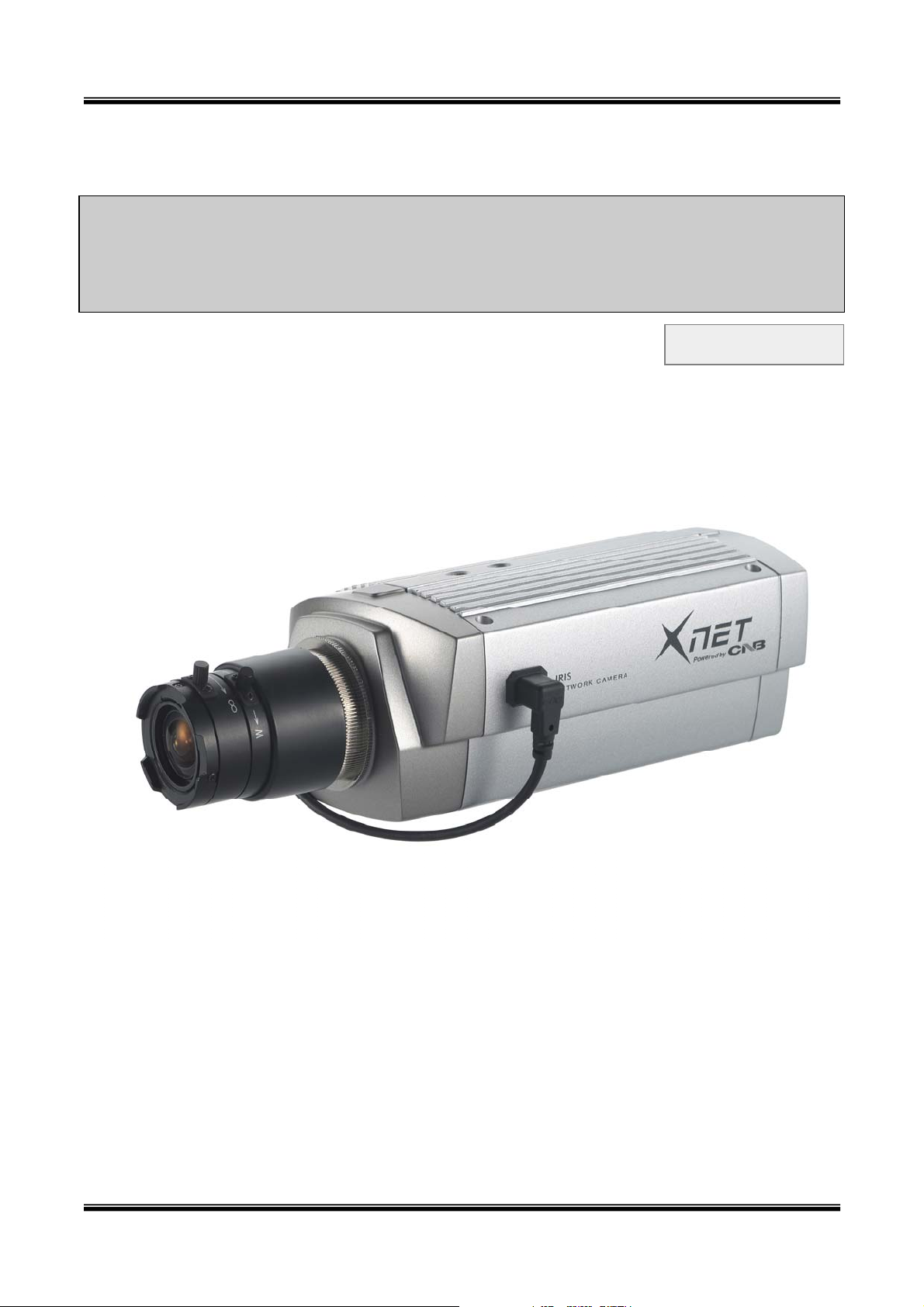
XNET Network Box Camera
User’s Guide
Ver. 1.0 (070918)
1 of 47
Page 2

XNET Network Box Camera User’s Guide
Directions
This product is designed for indoor use only. When using this camera at outdoors or in an
environment that exceeds the limited range, you must separately use a water-resistant case.
Be careful not to cause any physical damage by dropping or throwing the unit. Especially keep
the device out of reach from children.
Do not disassemble this camera. You will be excluded from After Service when disassembled.
Use only the power adapter provided with this product.
If you would like to use this camera for security, monitoring, please check the legal
regulations within the country.
Note
This equipment has been tested and found to comply with the limits for a Class A digital
device, pursuant to part 15 of the FCC Rules. These limits are designed to provide
reasonable protection against harmful interference in a residential installation. This
equipment generate, uses and can radiate radio frequency energy and, if not installed
and used in accordance with the instructions, may cause harmful interference to radio
communications. However, there is no guarantee that interference will not occur in a
particular installation. If this equipment does cause harmful interference to radio or
television reception, which can be determined by turning the equipment off and on, the
user is encouraged to try to correct the interference by one or more of the following
measures:
z Reorient or relocate the receiving antenna.
z Increase the separation between the equipment and receiver.
z Connect the equipment into and outlet on a circuit different from that to which
the receiver is connected
z Consult the dealer or an experienced radio/TV technician for help.
Caution
Any changes or modifications in construction of this device which are not explicitly
approved by the party responsible for compliance could void the user’s authority to
operate the equipment.
This appliance and its antenna must not be co-located or operating in conjunction with
any other antenna or transmitter. A minimum separation distance of 20 cm must be
maintained between the antenna and the person for this appliance to satisfy the RF
exposure requirements.
2 of 47
Page 3

XNET Network Box Camera User’s Guide
Table of Contents
1. Introduction.......................................................................................................................................... 4
1.1. Overview.................................................................................................................................. 4
1.2. Features of XNET/XNET-Wireless ...................................................................................... 4
1.3. Applications of XNET/XNET-Wireless................................................................................ 4
2. Product Description............................................................................................................................. 5
2.1. Contents................................................................................................................................... 5
2.2. Preview.............................................................................................................................. ....... 5
2.3. Physical Description............................................................... ............................................... 6
2.4. PC Requirements ................................................................................................................... 9
2.5 Quick Installation Guide........................................................................................................ 9
3. Connecting XNET/XNET-Wireless to the Network............................................................... ........... 12
3.1. Connecting to LAN............................................................................................................... 12
3.2. Connecting to xDSL/Cable Modem ............................................................... .................. 13
4. IP-Installer.............................................................................................................................. ............ 14
4.1. Main window of IP-Installer.............................................................................................. 14
5. Configuring XNET in Administrative Mode ...................................................................................... 15
5.1. Log On .................................................................................................................................... 15
5.2. Basic Setup............................................................................................................................ 16
5.3. Network Configuration ....................................................................................................... 19
5.4. Wireless Configuration(XNET-Wireless Only)............................................................... 22
5.5. CCD Adjustment ............................................................... ................................................... 24
5.6. User Admin & Time Setup................................................................................................. 26
5.7. Sensor & Capture Setup............................................................... ..................................... 29
5.8. Alarm Device Setup ............................................................................................................ 31
5.9. Motion Region Setup........................................................................................................... 32
5.10. PTZ Setup(Zoom is not applicable for XNET/XNET-Wireless)............................... 34
5.11. Encryption Set up.............................................................................................................. 36
5.12. Upgrade & Reset................................................................................................................ 38
5.13. Status Report ..................................................................................................................... 40
6. Tips for using XNET/XNET-Wireless................................................................................................. 41
6.1. ALARM-IN and ALARM-OUT .............................................................................................. 41
6.2. Trouble Shooting.................................................................................................................. 44
6.3. Web Viewer............................................................................................................................ 45
6.4. How to Upgrade the XNET/XNET-Wireless.................................................................... 47
3 of 47
Page 4

XNET Network Box Camera User’s Guide
1. Introduction
1.1. Overview
The XNET is a state-of-the-art network camera which transmits synchronized video and audio
data in real time with D1 resolution at full frame rate. This is possible through MPEG4 CODEC
technology, which provides high quality video with highly compressed data streams. This
products can be connected, controlled and monitored from a remote location through an IP
connection over internet or intranet. Unlike other CCTVs or DVRs, the XNET is easy to install
and user will experience cost and space savings in the install ation.
Based on Embedded Software Solution (Embedded Web Server, Embedded Streaming Server,
Network Protocol), the XNET ensures unprecedented performance and stability to be an ideal
network camera solution for system integration solutions.
The wired XNET series is offered with standard Ethernet interface while the wireless XNET series
is offered with embedded WiFi solution.
1.2. Features of XNET
y 1 nnel synchronized real time Video/Audio streaming cha
MPEG-4 video, ADPCM audio.
y B ectional audio communication
i-dir
Real time audio communication between the product and the client PC
y The viewer assisted recording and playback functions.
y 1 Alarm sensor input/1 relay output
y M n detection – Up to 3 motion detection zones
otio
y A ary shape motion detection zone
rbitr
otio
y M n detection can initiate video recording, which is sent to the user through F TP and/or E-
mail.
esol
y R ution
NTSC : 720x480, 352x240, 176x144.
PAL/SECAM : 720x576, 352x288, 176x144
y RS-485 interface for Pan/Tilt device connection
y R te administration control
emo
Entire operational parameter set up, Software upgrade
y Embedded WiFi interface (XNET-Wireless only) – IEEE 802.11b/g
y Proprietary PoE (Power over Ethernet) for convenience of installation and cost savings
1.3. Applications of XNET/XNET-Wireless
ecur
y S ity surveillance (buildings, stores, manufacturing facilities, parking lots, banks,
4 of 47
Page 5
XNET Network Box Camera User’s Guide
government facilities, military, etc.)
y R ime Internet broadcasting eal t
emo
y R te monitoring (hospitals, kindergartens, traffic, public areas, etc.)
eleco
y T nference (Bi-directional audio conference)
emo
y R te Learning
eath
y W er and environmental observation
2. Product Description
2.1. Contents
Open the package and check if you have the followings:
Components Description Remarks
XNET/XNET-Wireless XNET/XNET-Wireless Network Camera
Power adapter
AC power cable AC 250V, 10A~16A
Antenna XNET-Wireless only
CD-ROM Software & User’s Guide
Quick Reference Guide Quick installation guide Will be provided
Input : 100~250V 50-60Hz
Output : +12V, 3.33A
Standard Power
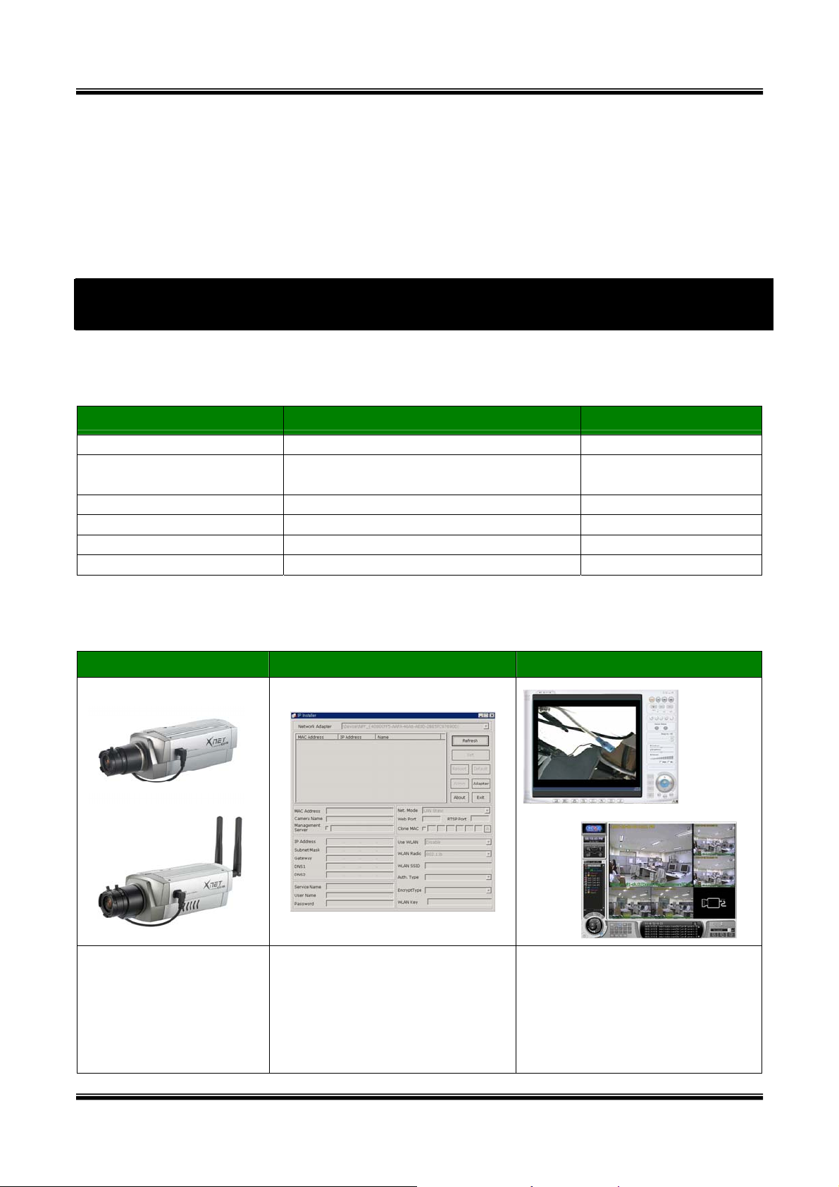
2.2. Preview
XNET/XNET-Wireless IP-Installer XNET-NVR
Wired LAN Type
Wireless LAN Type
PC software to view and record
the A/V streaming data
MPEG-4 Network
PC software to allocate an IP
transmitted from the XNET.
Camera
address to the XNET
There are two editions available
(NVR/XNVR).
5 of 47
Page 6
XNET Network Box Camera User’s Guide
2.3. Physical Description
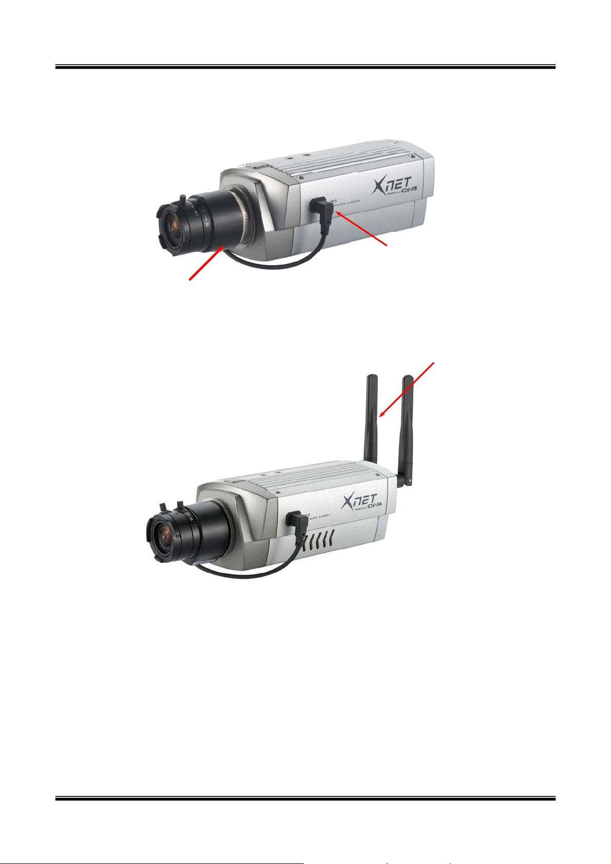
2.3.1. Side View
Lens
Figure 2-1. Side view of IG Series (Wired LAN)
Auto-Iris Control
Antenna
Figure 2-2. Side view of WG Series (Wireless LAN)
y L XNET/XNET-Wireless basically delivered without Lens assembly. Standard C or CS type
ens:
lens can be accommodated into XNET/XNET-Wireless. Either DC Iris lens or Non-DC Iris lens
can be used with XNET/XNET-Wireless.
uto-
y A Iris Control: Plug in the cable from standard DC-Iris lens.
nten
y A na: This antenna is used only f or the XNET-Wireless cameras(WG Series) to transmit
images via wireless network.
6 of 47
Page 7
XNET Network Box Camera User’s Guide
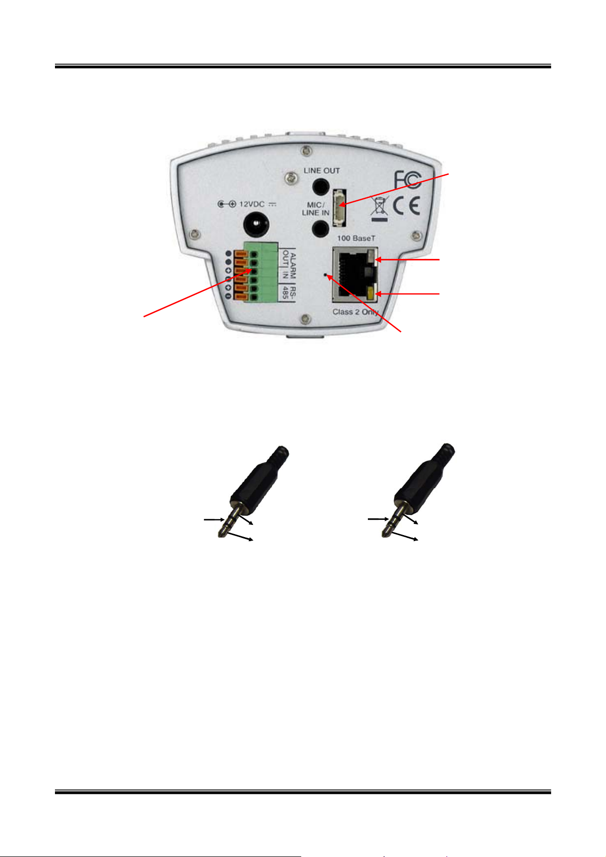
2.3.2. Rear panel
RS232C &
Analog Video Out
Status LED
Link LED
RS485 &
Reset Button
Alarm Input / Output
Figure 2-3. Rear Views of XNET/XNET-Wireless
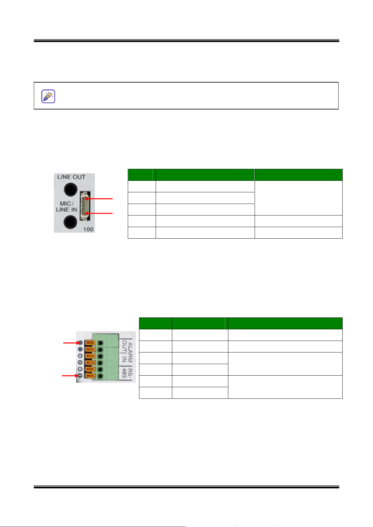
y MIC /LINE IN: Connect external audio source or microphone. Use a standard stereo
earphone jack for the connection
Not used
Not used
Not used
Ground
Ground
Audio In
Audio In
Not used
Ground
Ground
Audio out
Audio out
Figure 2-4. Pin assignment of the plug for MIC / LINE IN (left) and
LINE OUT (right)
y LINE OUT: Connect speakers with built in amplifier. Audio from remote site is output through
Line out in bi-directional audio mode. Use the standard stereo earphone jack for the
connection.
y Reset Button: Factory Default Switch
There is a switch provided for returning the network camera to factory default state. Press the
switch about 3 seconds through a tiny hole at the left of the 100BaseT connector using tools
with sharp tip for a few seconds while power is applied.
7 of 47
Page 8
XNET Network Box Camera User’s Guide
y 1 aseT: 100Mbps Ethernet connector (RJ-45) with proprietary PoE. 00B
- Status LED: Green color indicates that the camera is in normal operation mode, while red
color indicates that the camera is in abnormal condition.
When connecting a power source to the XNET, the status LED will be lit red for a
second and then it will change to green.
- Link LED: Continuous yellow light means that network cable is plugged in. It will flicker
when there is traffic.
S-2
y R 32C & Video-out: 3 Pins from the bottom of the connector are assigned for RS-232
port, while the remaining 2 pins are used for checking composite video output from the
camera. Please note that the bottom most pin is numbered as 1.
Pin Description Misc.
1 TxD of RS-232C
For debugging & factory
5
1
2 RxD of RS-232C
use only.
3 Ground of RS-232C
4 Video out from the camera For use in installation.
5 Ground for Video out. For use in installation
y 1 C: Power input of XNET/XNET-Wireless.
2VD
Do not apply power through this power input when power is applied through LAN cable using
proprietary PoE.
y RS-485 and ALARM IN/OUT: Used for connecting P/T device, sensor, and alarm devices to
XNET/XNET-Wireless. Pin assignments are as follows
Pin Description Misc.
1 RS-485 (-)
6
2 RS-485 (+)
3 Alarm In (-)
NC/NO selectable in admin mode.
4 Alarm In (+)
1
5 Alarm Out
See section “6.1. ALARM-IN
6 Alarm Out
and ALARM-OUT”
- RS-485: Used for connecting Pan/Tilt and Zoom devices having RS-485 interface standard.
- Alarm In: Connect external alarm sensors such as the infrared sensors, heat sensor,
magnetic sensors, etc. NC/NO selectable in the admin page.
- Alarm Out: It is used for connecting external alarm generators such as sirens, flashing light,
etc. When activated, relay output configures a closed circuit.
Please refer to Section 6.1 for more detailed description on the Alarm In/Out connections.
8 of 47
Page 9
XNET Network Box Camera User’s Guide
y A na Connector: Connector for connecting 3dBi antenna supplied with XNET-Wireless nten
.4. PC Requirements
2
AV streaming data receive
XNET-NVR program which is a viewing & recording program for a PC. Minimum requirement of
the PC is described below:
Item Minimum Recommended
CPU Pe 0 Pen ve ntium III 70 tium IV 1.2G abo
Main Memory 128 MB 256MB above
Op
Web browser Internet Explorer 5.0 Internet Explorer 5.0 above
Resolution 1,024*768 Higher than 1,024*768
Network 10 B et ase-T Ethern 100 Base-T Ethernet
* Supp : Windows 200
2.5 Quick Installation Guide
Brief information for rapid instal
you are recommended to refer to pertinent documentations provided with the product or refer
orted O/S 0 Professional
*
Windows XP Professional / W
d from XNET/XNET-Wireless can be decoded or stored in a PC running
Window r later Wind ter erating system s 2,000 o ows 2,000 or la
indows XP Home Edition
lation is provided in this section. For more detailed information
to our official website. (
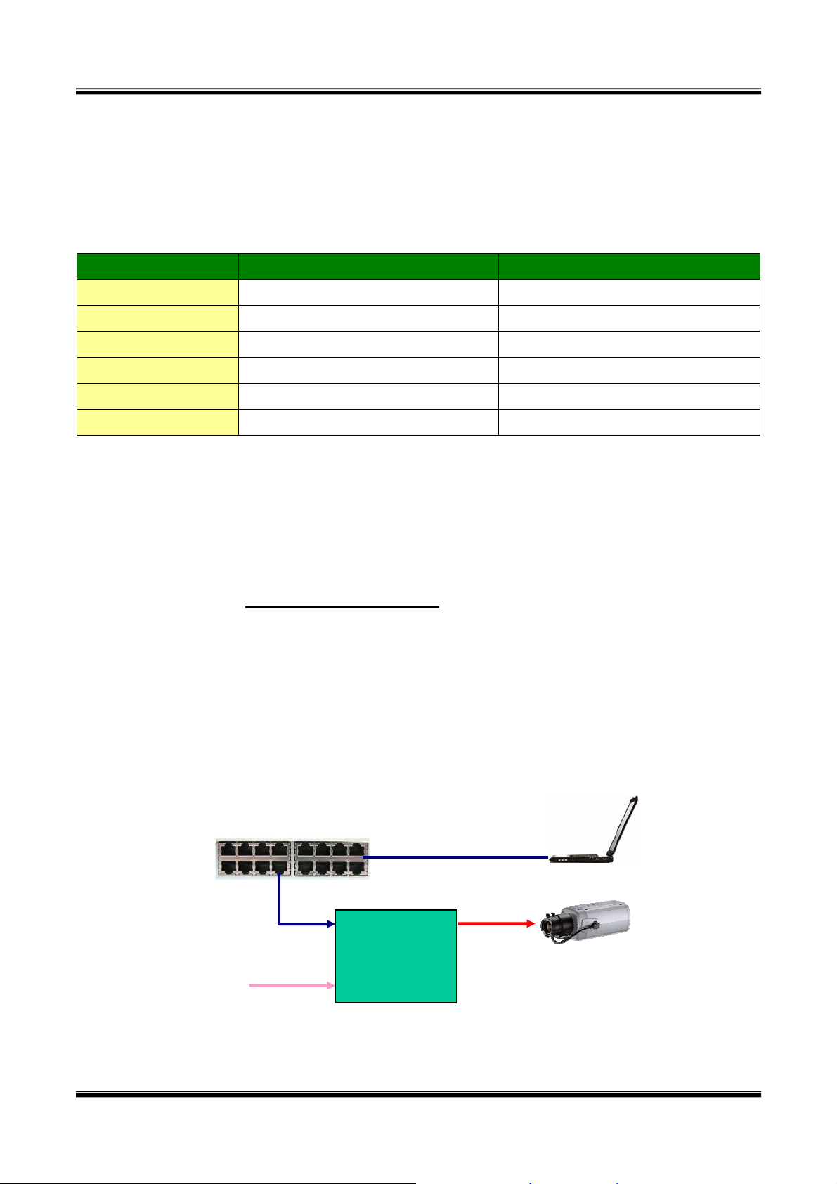
① Connect XNET/XNET-Wireless to the LAN by using one of the following method
i. If you have power adaptor with PoE, connect the network camera and PC as illustr
in Figure 2.5. Both power and network connection is made with a single LAN cable. The
propriety PoE (Power over Ethernet) adds convenience in installing the network camera
by providing both power and LAN connection using single LAN cabling.
http://www.cnbtec.com)
LAN Hub
PC
100BaseT
LAN
PoE Adaptor
AC In
Cam
XNET
ated
Figure 2-5. Connecting Network camera and PC using PoE Adaptor
9 of 47
Page 10
XNET Network Box Camera User’s Guide
n
10 of
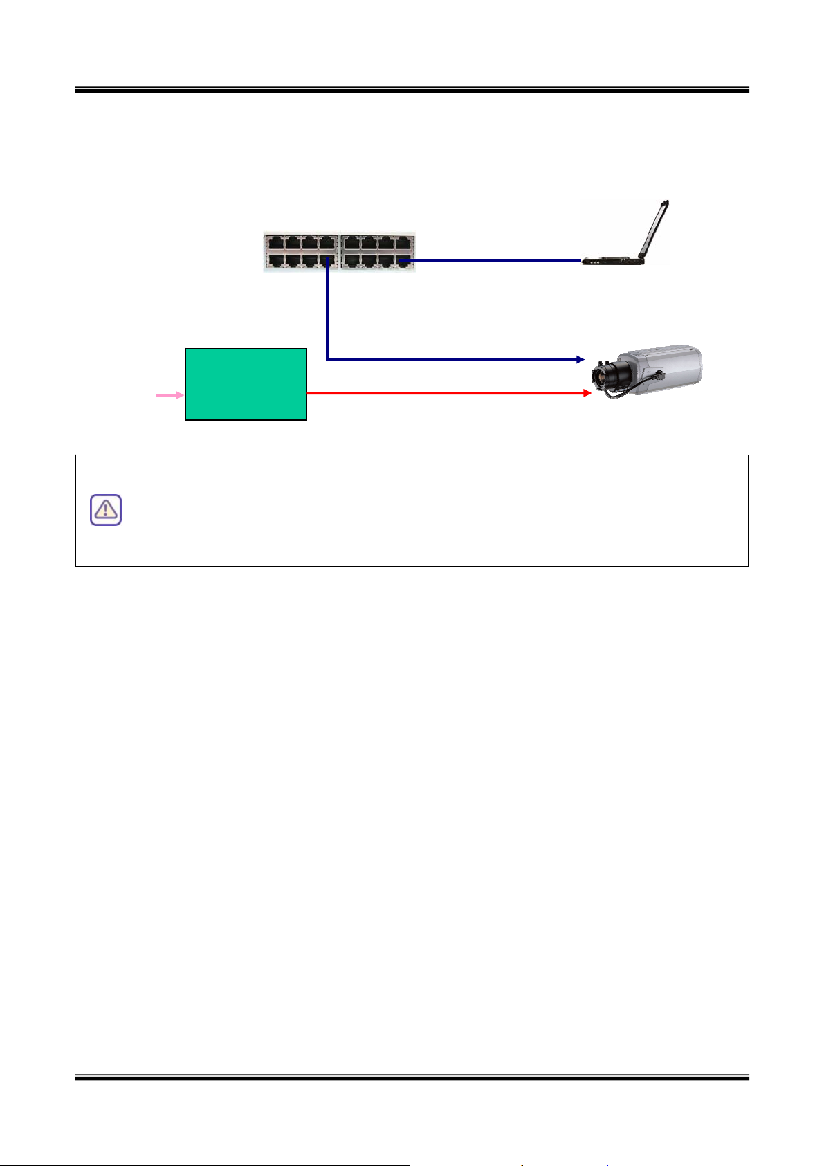
ii. If you have standard power connect the network camera and PC as illustrated in Figure
2.6.
LAN Hub
PC
100BaseT
AC Adaptor
DC I
AC In
XNET
Figure 2-6. Connecting Network camera and PC using AC Adaptor
The XNET Series does not support standard PoE. Do not connect the network
camera directly to a hub supporting standard PoE. We assume no
responsibility for the damages caused by use of standard PoE device with
this product.
② Install “IP installer” and “XNET-NVR” on your PC
Detailed information for installing these software can be found in [IP-Installer User’s
Guide] and [XNET-NVR User’s Guide] respectively.
③ Assign IP address to XNET/XNET-Wireless using IP installer
Identify the type of the network environment and set up IP address. Detailed process of
setting up IP address can be found in [IP-Installer User’s Guide]. If network type is xDSL or
Cable modem you need supplementary information provided by your ISP.
④ Connect to the XNET in Administrative Mode for initial parameter set-up
All parameters are set to factory default state when XNET/XNET-Wireless is delivered. You
are asked to configure the system for your environment in administration mode. Detailed
information of using administration mode can be found in [5. Configuring XNET/XNET-
Wireless in Administrative Mode]. Among the parameters, the parameters in the
following table should be set-up with proper values. Detailed information for the parameters
in Administrative Mode is found in [5. Configuring XNET/XNET-Wireless in
Administrative Mode]
[Note]: Set-up values are preserved even the power is turned off.
The table below shows the Administrator Mode’s parameters list.
Page 11

XNET Network Box Camera User’s Guide
P e ag Parameter Setup value Factory default value
Set the resolution of the video
Basic
Setup
User
Admin &
Time
Setup
Video Size
Max Upload Rate
Frame Rate
Video Rate
Administrator
password corresponding fields. Do not disclose
transmitted from XNET/XNET-
Wireless.
Set this value smaller than the
upload speed of your network.
The number of frames to be
transmitted per second.
Bandwidth assigned for video
transmitted from XNET/XNET-
Wireless.
For safety, you are recommended to
change these values from factory
default. For new connection, you Default value
these values to others and
memorize these values.
Make sure that you press Check
button to find out the number of
maximum possible simultaneous
users then set the number of
users smaller than or equal to
the number.
name & need to input changed values for Username : root
Password : dw2001
Current Ti
me Input correct time in this field.
Default value :
2001/1/1
Connect the input and output signals to XNET/XNET-Wireless
⑤
Connectors Function Signal description Number
LINE-
Connect microphone or outpu
t from audio
Audio in
In/MIC
devices.
Audio from remote site is available from
Line Out Audio out for speaker
this connector in bi-directional au
dio 1
mode. Connect speaker with amplifier.
Connecting Alarm
IR sensor, Motion Sensor, Smoke
Alarm In
Sensor
Detector…
Connecting Alarm
Alarm Out
Siren, Flashing Light, … 1
annunciating device
Remote P/T/Z device connection having
RS485 PT device control
RS485 interface.
1
1
1
1
1 00Base-T Network connection
network, LAN, ADSL or Cable modem.
12VDC Power connector The input power source is 12VDC 1
Connect XNET/XNET-Wireless to the
11 of 47
Page 12
XNET Network Box Camera User’s Guide
12 of
⑥
Remote video connection to XNET/XNET-Wireless
Run “X NVR” on your P e connecting T-Wireless it is needed
configure the connection infor ore detailed information of using
“XNET-NVR” c d in [X
⑦ Brightness adjustment
Adjust the brightness setting f rom
administra ac ode
username (default: roo ssword (default: dw2001)
NET- C. Befor to XNET/XNE to
mation on the XNET-NVR. M
an be foun
tor mode. When
t) and pa .
NET-NVR User’s Guide].
or optimized image quality f
cessing the administrator m
the CCD control menu in the
for the first time, enter the
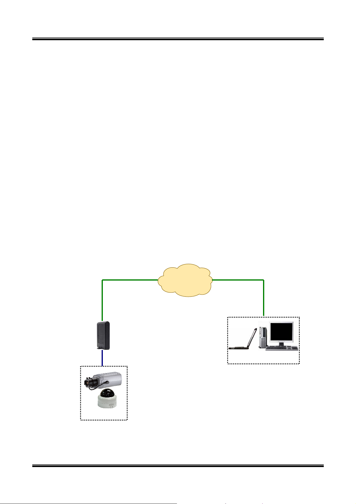
3. Connecting XNET/XNET-Wireless to the Network
XNET/XNET-Wireless supports . It also supports shared IP
environment where single IP ad devices. Refer to [IP-Installer
User’s Guide] set ET-Wireles
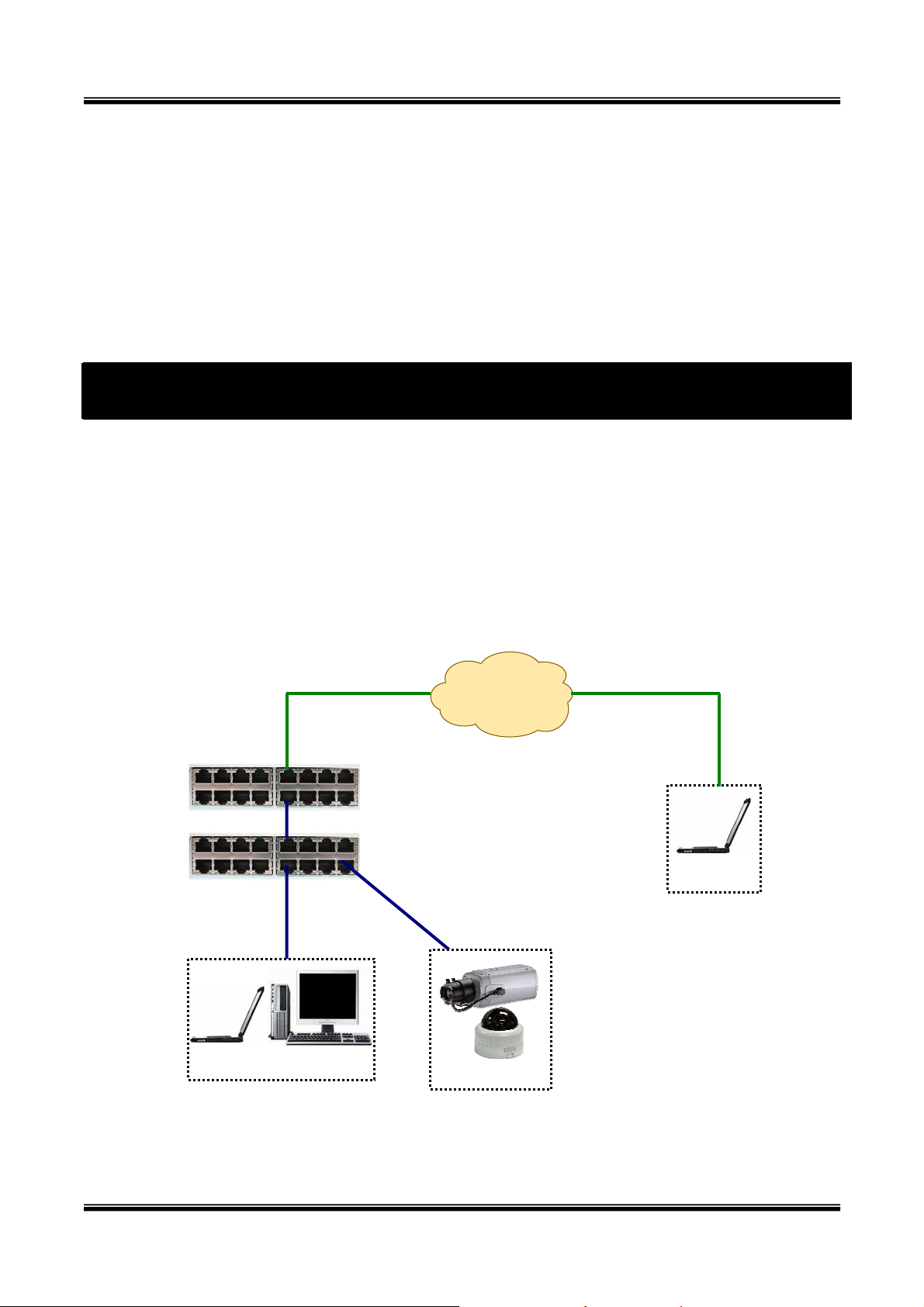
3. cting
1. Conne
In cas
for details of
to LAN
e of connecting the XNET is generally connected as in Figure
LAN, xDSL, and Cable modem
dress is shared by at least 2 IP
ting the IP address for XNET/XN
/XNET-Wireless to LAN, it
s.
3-1.
Router
Hub
Client PC
IP Network
(LAN/WAN)
XNET
Client PC
Figure 3-1. Conn
1) w through s ③ in Secti -
Follo
teps ① to on 2.5 to assign IP address to XNET/XNET
ecting the XNET to LAN
Page 13
XNET Network Box Camera User’s Guide
13 of
Wireless.
2) Install the viewer program (NVR or XNVR) and conn
3) Check if you can receive video data when connecting to XNET/XNET-Wireless using the
viewer program.
4) When one or more IP video products are connected
router) to a larger ne
the local area network, each device must have a unique RTSP (Real Time Stream
Protocol) and HTTP port number. You must also configure your IP sharing device for
“port forwarding”. This is to enable the IP sharing de
unique port number (RTSP and HTTP) to unique internal IP address (local IP address). If
you only plan to access multiple units from within a local area network, you do not n
to change the RTSP and HTTP port numbers, unless other IP sharing devices sit
between the client and the IP video products. For more detailed information regarding
the use of IP sharing device refer to the document [Use of Private IP network using
IP-sharing-device].
.2. Connecting to xDSL/Cable Modem
3
1) Follow through ste
twork (i.e. the internet), in order to access each unit f rom outside
ps ① to ③ in Section 2.5 to assign IP address and other network
ect it to desired LAN.
through a IP sharing device (i.e.
vice to forward packet data with
②
eed
in-
parameters to XNET/XNET-Wireless.
nstall XNET/XNET-Wireless and connect it to xDSL or Cable modem as in Figure 3-2.
2) I
IP Network
(LAN/WAN)
xDSL/
Cable
Modem
XNET
Client PC
Figu m
re 3-2. Connecting the XNET to ADSL Mode
Page 14
XNET Network Box Camera User’s Guide
When a static IP address is assigned to the xDSL or Cable modem, follow the same
way as assi
notification of the changed IP address to the user over e-mail when the IP addre
changed in dynamic IP environment, you have to assign the e-mail address when
user name and pass
When connecting XNET/XNET-Wireless to xDSL or Cable modem, usually a
straight LAN cable is required. But since some modems have crossover
connections, in this case, you should use a crossover LAN cable. Please contact
your service provider for detailed information.
gning a IP address for the case of LAN using IP-installer. To enable the
ss is
word are input using IP-installer.
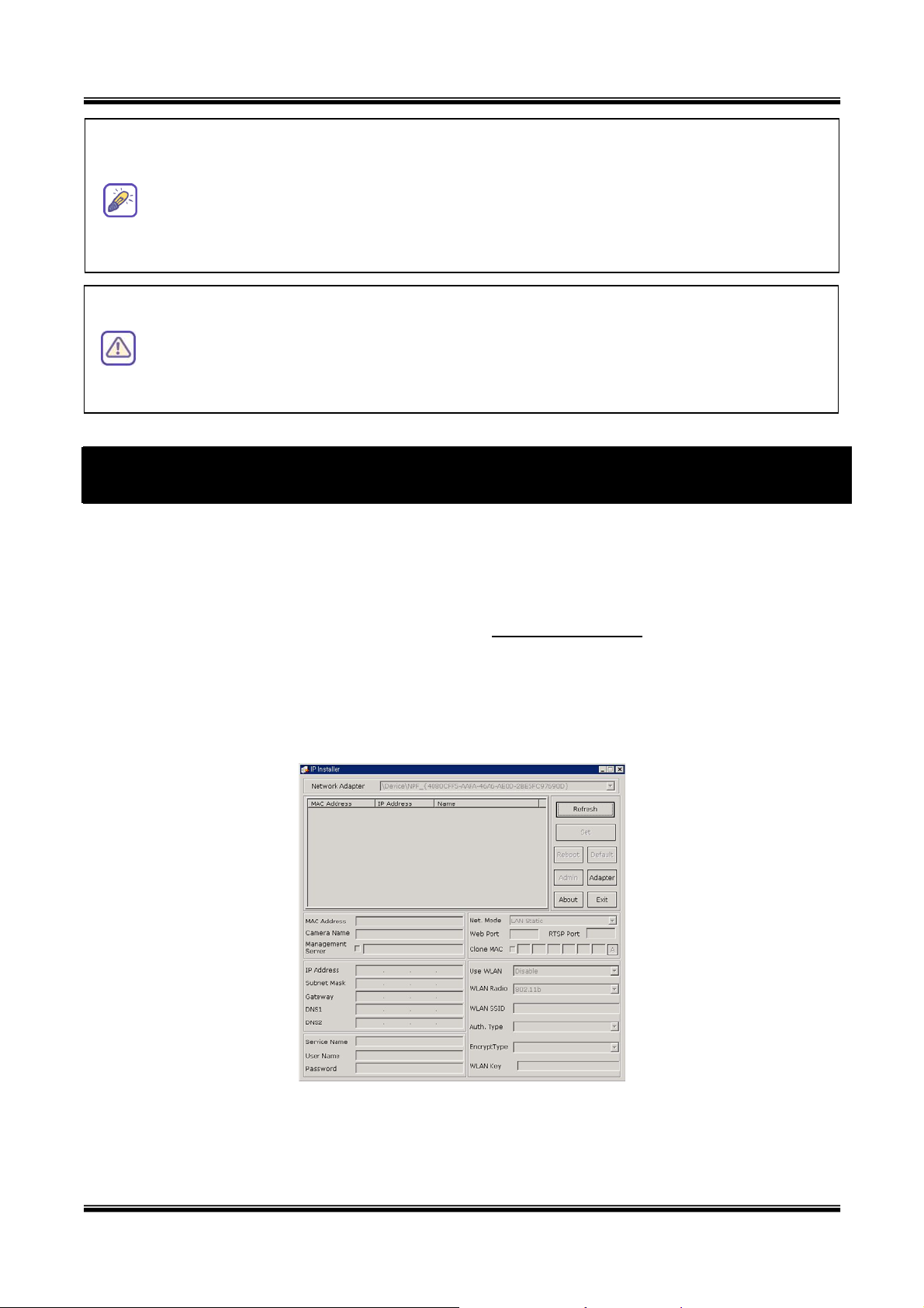
4. IP-Installer
XNET/X IP network parameters for connection to the network
(In rnet/Intranet). IP-Installer is a PC program for the initial net work configuration to IP video
products such as Network Camera or A/V S su
NET-Wireless needs
te
erver. IP-Installer is provided in a CD pplied with
XNET/X
Detaile running IP-installer can be found in [IPins
4.1. Main window of IP-Installer
NET-Wireless or it can be downloaded from “
d information of Installing and
taller user’s guide]
www.cnbtec.com”.
Figure 4-1. IP Installer
All the basic network parameters needed for the initial connection to IP video products can be
assigned by IP-Insta initial connection is
ller. Once the basic parameters are assigned and the
14 of
Page 15
XNET Network Box Camera User’s Guide
15 of
successfully made, you can connect to the administration page for more sophisticated control of
the network parameters and other operational parameters. Refer to Chapter 5 for more details
of the administration page.
5. Configuring XNET in Administrative Mode
5.1. Log On
There are two ways of connecting to XNET/XNET-Wireless administrative mode. One is through
Internet Explorer (IE) and the other is through “XNET-NVR” or “XNET-XNVR” program. But
this user’s guide will explain accessing by IE and “XNET-NVR” only. (Please refer to the XNVR
user’s guide in the supplied CD for using “XNET-XNVR”.)
5.1.1. Log on from Inter
The URL of the XNET
http://[Allocated IP address]/admin.htm
Example: http://172.16.64.133/admin.htm
net Explorer
administrative mode is as followings:
If you changed the HTTP port from default value you can login by typing in:
http://[XNET/XNET-Wireless IP address]:[HTTP port]/adm
Example: http://172.16.64.133:8080/admin.htm
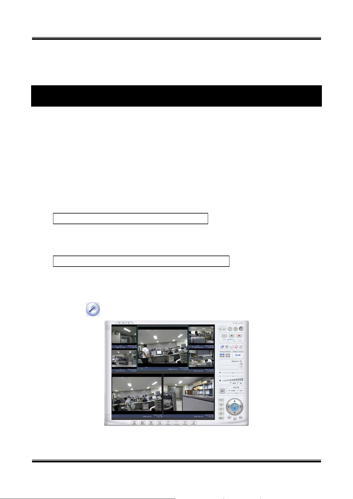
.1.2. Log on from “XNET-NVR”
5
Select video channel in the viewing window of “XNET-NVR”. Select
highlight
ed. Click
button on the right side of the display screen.
in.htm
ed video channel will be
Figure 5-1. Log on from “XNET-NVR”
to administrative mode
Page 16

XNET Network Box Camera User’s Guide
16 of
5.1.3. Input User Name and Password
After fallowing the method which explained in Section 5.1.1. or 5.1.2, the login screen will open.
Input the User Name and Pa
ssword in the login screen shown in Figure 5-2.
Figure 5-2. Login screen
The default setting for the User Nam
e and Password are ‘root’ and ‘dw2001’, respectively. Click on
“OK” button to enter into the Basic Setup page of Administrative Mode. If you have changed the
username and d of the Administrator, you must log on with the changed username and
passwor
password.
After login to t nd password for
security. Setup” for detailed
Please refer to section 5.6. “User Admin & Time
he administrative mode, change the user name a
information.
If you forget t is by resetting the
unit to factory he settings go back
to default. In meters again. Please refer
the user name and password, the only way to reset i
default through the reset button. It will make all t
this case, you have to setup the network para
to section 3.
Page 17

XNET Network Box Camera User’s Guide
17 of
5.2. Basic Setup
Setup the basic parameters of the XNET/XNET-W reless.
i
Field/Button
Sub Field
/Button
Language
System Name
Screen Capture
in Web Viewer
Figure 5-3. Basic Setup
Description
Select a language of your choice. English, Korean, Chinese,
Japanese, Spanish, Italian, Portuguese are available.
Logical name of the XNET. It is same as the one set-up by IPinstaller. You can reassign the system name.
Save a image file captured from the web viewer to the folder of
your choice. The file name format is as fallows
Capture_year_month_day_minute_second.bmp.
Page 18

XNET Network Box Camera User’s Guide
18 of
Audio Input
Selection
Select the type of input audio.
Select Line In for
Select Mic for using microphone.
Input Video This filed is set by the factory
Select a video size for transmission-
Video Size
Interpolation/
De-Interlace
Max. upload
rate
z NTSC(30 fps Max.): 720x480, 352x240, 176x144
z PAL/SECAM (25 fps Max.): 720x576, 352x288, 176x144
Select the imaging method when the video resolution is Full D1.
z Interpolation: Filtering not used. Provides clear images than
De-Interlace method, but a jaggy image will appear to the
moving object.
z De-Interlace: Using filtering. Proper to the moving objects,
but not clearer than Interpolation method.
Assign maximum bandwidth of the uplink for the network
connected to XNET/XNET-Wireless.
Assign number of video frames to be transmitted for each second.
using Line-out from audio devices.
Video Quality &
Bandwidth
Control
Frame rate
Video rate Assign bandwidth for transmitting video data.
Audio rate
Check
Possible Max
Users
Remained
Limited users
You can improve picture quality by lowering frame rate for the
same bandwidth.
Assign bandwidth for transmitting audio data. Audio data is not
transmitted if you select “NA”
After you finish set up of video and audio for all the channels, click
on this box to obtain the possible maximum number of users
(Possible Max Users) and remaining network bandwidth
(Remained) remaining when possible maximum users are
connected.
It shows the number of maxi
the network connection set-up.
It shows the network bandwidth remaining when Possible Max
Users are connected.
Useful network bandwidth varies according to the condition of the
network. This parameter is used to limit the number of the
simultaneous connections below the number shown in
mum simultaneous connections for
Possible
Max Users.
Save parameters are done.Save the set-up parameters when the set-up
Page 19

XNET Network Box Camera User’s Guide
19 of
5.3. Network Configuration
Setup the network para eters approp ment.
Many of the parameters in this page are er”.
m riately in accordance with your network environ
same as those set up by “IP-Install
Figure 5-
4. Network Configuration
Page 20

XNET Network Box Camera User’s Guide
20 of
Field/Button
IP Assign
Type
Sub Field
/Button
Static IP
Setup
PPPoE Setup
DHCP Setup
Description
The network types supported by the XNET/XNET-Wireless are
LAN(fixed IP), PPPoE, and DHCP(automatic IP allocation)
When the network environment is fixed IP, select ‘LAN’ in the
network type, and put the IP address, Subnet Mask,
Gateway, DNS1 and DNS2. Ask your network administrator
or ISP for the information. DNS2 is used when DNS1 does
not work.
When the network environment is PPPoE and IP address is
assigned automatically, select ‘PPPoE’ in the network type.
Next, fill in the ‘User Name’ and ‘Password’ fields with the
values assigned by the ISP.
When the network environment is “automatic IP allocation by
DHCP”, select ‘DHCP’ in the network type. For cable modem
connection, select this mode.
Refer to [IP-installer user’s guide] for “Host name and
Port Change
IP Filtering
domain for Cable Modem
Clone MAC Refer to [IP-installer user’s guide] for “Clone MAC”
Each port should have a number below 65,535.
The RTSP port is used for transmitting real time audio/video
RTSP
data from the network camera. Default is 554.
HTTP port is used for the connection to the admin page.
HTTP
Default is 80.
You can restrict the access to the administrator page from IP
addresses beyond certain IP address range.
Restrict
Check at this box to restrict administrative log on.
Administrator
Access
Base IP
Address
Input IP address of the PC which is intended to be used for
log on to administrative mode.
This is same as subnet mask
. It is used to allow
administrative log on only to the PCs located in the same
E-Mail Setup
Mask
Notify for IP
Change
subnet as the base IP address. If you want to allow only one
PC to access in administrative mode, set this value to
255.255.255.255.
If you check this, the IP address will be sent via E-mail
whenever the IP address changes. It is sent to the E-mail
Page 21

XNET Network Box Camera User’s Guide
21 of
address set by “Recv E-Mail Address”.
FTP Server
Setup
R
Address
Return E-Mail
Address
Using Built-in
SMTP Server
Using
External
SMTP Server
Enter E-mail address to receive information sent from your ecv E-Mail
network camera. This is same as E-mail field in IP-installer.
mail sent from the network camera
If you are using web mail services having no SMTP
check the radio button at the left of “Using Built-in SMT
server,
P
Server” and enter valid e-mail address to avoid spam
filtering on
the receiving e-mail server.
If you are using external mail server, fill in the fields with
proper parameters.
Setup IP address, Username
, Password and Directory of FTP
server to send data in case of alarm. Default FTP port
number is 21.
You can register the network
Server (DDNS Server) for name service to your netwo
camera to the Management
rk
camera.
Fill in this field with correct e-mail address to identify the
Management
Server
Save
Log on to
server
Check this box to enable log on to the management s
By log on to the management server your netw
erver.
ork camera
can use domain name instead of numeric IP address. This
feature is particularly useful when your netwo
rk camera is
using dynamic IP address. Input valid management server
(DDNS Server)
name for the service.
You must have an account on the management server
(
http://mgmt.ipdvrfree.com/) and register your IP video
devices under your account to use this feature.
Domain name of your network camera can be assigned when
you register your network camera to the management server
under your account.
Save the set-up parameters when the set-up parameters are
done.
Page 22

XNET Network Box Camera User’s Guide
22 of
5.4. Wireless Configuration (X
For the case of a er
LAN configuration pa . Cli
network cam
rameters
NET-Wireless Only)
a having built in wireless LAN it is needed to set up wireless
ck “Wireless Configuration”.
Field/Button
Wireless LAN
Setup
Figu
re 5-5 Wireless Configuration
Sub Field
Description
/Button
Select “ESS” to use wireless interface. If “Disable” is
WLAN Mode ireless LAN
selected, Ethernet interface is used instead of w
interface.
WLAN Radio Select the mode of Wireless Radio.
Enter the ID of th
e wireless LAN access point to be
SSID
connected when wireless LAN interface is selected.
Authentication Select the type of authentication.
Select
the mode of encryption. If encryption is not needed,
Encryption
select “OFF”
Key Set the value of encryption key or pre-shared key.
Power level Set the maximum transmission power level or wireless LAN.
Information
MAC Address Indicates MAC address of the wireless LAN. WLAN
Indicates the ID of the connected access point. In general
BSSID
Page 23

XNET Network Box Camera User’s Guide
23 of
the MAC address of the access point is shown.
Current
Channel
Signal
Strength
Link Quality Indicates the quality of Link level.
Tx Rate Indicates the speed of the latest transmission
Indicates the channel number of present connection.
Indicates the strength of the received signal.
Page 24

XNET Network Box Camera User’s Guide
24 of
5.5. CCD Adjustment
You can optimize the f inp into this
mode, click “CCD Ad t” in administrative page. You will find a screen shown in Figure 5-
quality o
justmen
ut video by adjusting the parameter of CCD. To ent er
6.
Figure 5-6. CCD Adjustment
Sub Field
Field/Button Description
/Button
Standard XNET is delivered without lens. Any lens having C
or CS mount type can be installed on XNET.
A C-CS adaptor is packaged with XNET for accommodating
CS type lens. Confirm whether your lens is Non DC IRIS or
DC IRIS lens before your selection and then click “SAVE” to
Lens
Selection
save your selection.
DC IRIS lens is a kind of auto IRIS lens. Opening of IRIS can
be adjusted by applying DC voltage. The opening of IRIS is
DC Iris
optimally adjusted by detecting the signal level from CCD.
This type should be selected when DC IRIS lens is mounted
on your XNET/XNET-Wireless.
ELC Select this mode, wh en using a fixed focal lens.
Page 25

XNET Network Box Camera User’s Guide
25 of
When the camera is acquiring video from object with bright
CCD Control
Backlight
Compensation
Auto Gain
Control
Flickerless
backlight, it is hard to identify the details of target object
since the object appears very dark. Apply backlight
compensation mode for this case. Default mode is backlight
compensation OFF.
If you set the value to ON, the gain is automatically adjusted
in accordance with the illumination condition.
In case of using NTSC type iCanViewV230 in 50Hz AC
regions or using PAL type XNET/XNET-Wireless in 60Hz AC
region, video output tends to flicker when XNET/XN
ETWireless is used under fluorescent lamps. This mode reduces
the flickering phenomena. If this mode is selected, electronic
shutter speed is set to 1/100 sec for NTSC camera while
set to 1/120 for PAL camera to synchronize the shut
it is
ter
speed to AC current. The default value is OFF.
<Note> : Make sure that you apply this mode only wh
using NTSC camera in PAL region or PAL camera in NT
en
SC
region.
Day and
Set the value to ON to enable the camera’s day & ni
feature set. Under very low light conditions, the camera
Night
automatically switches to “Night Mode/Black and Wh
(option)
Mode,” delivering daylight quality Black & White video.
Setting the value to ON, tells
Digital Slow
video refresh rate in order to compensate for ultra low light
Shot
conditions, improving th d sharpness of the
(option)
video.
Digital zoom
Set the value to ON to enable digital zoom.
(option)
Adjust the amount of light reaching CCD manually.
Brightness
Select the value between 1 and 32. For brighter video select
Control
higher number.
SAVE your selection. Click “SAVE” to save
ght
ite
the camera to sacrifice the
e brightness an
Page 26

XNET Network Box Camera User’s Guide
26 of
5.6. User Admin & Time Setup
You can change the ID and passw ord of users and also assign different attributes for each user.
Fig
ure 5-7. User Admin. & Time Setup
Sub Field
Field/Button Description
/Button
Administration
Administrator
Username
Administrator
Admin ID. Default ID is “root” User
Admin password. The default password is “dw2001”.
password
Page 27

XNET Network Box Camera User’s Guide
27 of
Administrator Enter the password once more to confirm the password.
Confirm
Password
Add User
Username
Add User
Password
Add User
Attribute
User List
Enter the user ID you want to add. Up to 100 users are
supported by XNET/XNET-Wireless.
Enter the user password.
You can set different system resource access capabilities for
each of the users. Attributes are Audio, Bi-directional Audio
and Pan/Tilt control. For example, if you want a specified
user to hear the audio from the XNET/XNET-Wireless, check
Audio in the check box.
You can list “user ids” and “ their attributes” here.
format : user id[A, BA, P] :
A – audio,
B – bi-directional audio,
P – ptz(Pan/Tilt), not used for this model.
You can delete specific user by clicking the DELETE button.
If you want to restrict viewing access to the XNET/XNET-
YES
SAVE
Authentication
for Viewing
If no, default
attribute
Time Setup C It shows you the current time of XNET/XNET-Wireless. urrent Time
Wireless, check at the box left to Yes and click on Save.
Users need to input ID and password to connect to
XNET/XNET-Wireless. The a pop up window as shown below..
Figure 5-8. User authentication pop up
If the username or password are incorrect, an error message
will be displayed
If you uncheck for the Authentication for Viewing, all users
can access the XNET/XNET-Wir
eless with the same attribute
set here. Checked attributes are enabled. Click “Save” to
save the attribute.
Page 28

XNET Network Box Camera User’s Guide
28 of
Synchronize
with an
Internet
Ti
me Server
S
Synchronize the time with the internet time server at
right. When the time server is out of the reach from
XNET/XNET-Wireless, you can assign time server by filling in
Specific Time Server field.
Synchronize the time with the time o
With this
Computer
Time
Set Manually Set the time manually. Fill in the fields with desired formats.
SAVE Save the set up parameters
If you lost Administrator
reset the settings to factory defa u lose your previous settings.
’s ID and password, the only means of recovery is to
ult, but then yo
the
f the PC. ynchronize
Page 29

XNET Network Box Camera User’s Guide
29 of
5.7. Sensor & Ca
This is the setup pag sor
user by FTP or E-ma nfig
pture Setup
e for sen
il upon co
Figure 5-9. Sensor & Capture Setup
s and video capture conditions. Captured video can be sent to
uration.
Sub Field
Field/Button Description
/Button
Select sensor type. There are two types of sensors which are
Sensor 1
Normal Open and Normal Close. Sensor Setup
Name Input logical name for the sensor.
It sets the condition of video transmission via FTP or E-mail.
The XNET/XNET-Wireless supports 2 types of conditions which
are mutually independent.
Video Capture
Condition
Sensor
Select
Motion
Check to enable Sensor initiated capture.
Check to enable motion detection initiated capture.
Detection
Select
Captured
Select a way of sending captured video. You can send
Video
captured video through FTP or E-mail, or both.
Page 30

XNET Network Box Camera User’s Guide
30 of
Transmission
Check to send captured video by e-mail.
E-mail is sent to the Recv E-mail address.
Refer to [
Section 5.3.]
By E-Mail
Captured video data for E-mail consists of intra frames only in
consideration of the limited storage space for E-mail account.
FTP data contains entire video frames.
Check to send captured video by FTP.
FTP is sent to the FTP Server. Refer to [Section 5.3.]
By FTP
If the FTP server is not properly assigned in “Network
Configuration” mode, XNET/XNET-Wireless ignores the
video transmission by FTP
SAVE Save the setup parameters.
To prevent the client mail server's storage capacity excess, the system send only
video data (iframe data) to the client in the E-Mail mode. But in the FTP mode,
system sends all the data including the audio data and the full frame of video data. If
you want to transmi
t all the data, select the FTP transmission mode.
When the FTP server or email address is invalid, the transmission process will be
ed
discard
Page 31

XNET Network Box Camera User’s Guide
31 of
5 Setup
.8. Alarm Device
Test the alarm output and descri
Figure 5-10. Alarm Output Setup
Sub Field
Field/
Button Description
/Button
be the condition of alarm annunciation.
Test alarm devices. Click on On/Off for testing.
Small box with white background indicates the status of the
Alarm Device
relay by On/Off.
Test
ON On the alarm output (close the relay contact)
OFF Off the alarm output (Open the relay contact)
Sound Test Used for audio/voice testing
Setup the condition of activating alarm device. Select sensor
or motion detection as the condition.
Logical name of the alarm device can be input into the box at
Name
the left.
Alarm Device
Check at the box at the left of to allow alarm generation upon
Active
Sensor
sensor input.
Condition
Check at the box at the left to allow alarm generation upon
Motion
Motion detection
Set the duration of Alarm annunciation.
Duration
10/30 sec, 1/2/5/10/30 min, 1 hour.
SAVE Save the setup parameters.
Page 32

XNET Network Box Camera User’s Guide
32 of
5.9. Motion Region Setup
Set the motion detection regions. Up to 3 regions can be defined.
ure 5-11
Fig . Motion Region Setup
Sub Field
Field/Button Description
/Button
Channel
Not applicable.
Selection
Channel
Set the sensitivity in motion detection for each ch annel. 1 is
Sensitivity
the most sensitive, and 10 is the least sensitive.
Page 33

XNET Network Box Camera User’s Guide
33 of
Set up to 3 the motion detection zone
Enable each zone by checking the box at the left of each
Region.
To set the region:
Motion Region
Setup
SAVE Save the setup parameters.
Region 1, 2,
Click on START and click on a box overlaid on the video
Click on END and click on a box overlaid on the video.
or 3
The defined motion detection zone will be indicated with
corresponding colors.
Legend of the color:
Region 1: red, Region 2: green, Region3: blue.
START Enable selection of rectangular zone start.
END Enable selection of rectangular zone end.
Click on this button and click on desired rectangle to add or
SELECT
delete the rectangular region to the motion detection zone.
This value controls the sensitivity of each region.
Percentage
1 is the most sensitive and 100 is the least sensitive
RESET Clears the start & end point to (0,0) & (0,0)
Page 34

XNET Network Box Camera User’s Guide
34 of
5.10. PTZ Setup
Setup and test the PT(Pan/Tilt) de
vices.
Figure 5-12. PTZ Setup
Sub Field
Field/Button Description
/Button
Channel
Not applicable
Selection
Choose the PT model.
PTZ Model
Delete
Press this button to delete the setup of PT
Selection
Button
Your PT device needs an ID, input ID in this field.
PTZ Device ID
Click on SAVE to save the ID.
Note that zoom is not applicable for XNET
Page 35

XNET Network Box Camera User’s Guide
35 of
PTZ
Operation
Check
PTZ Position
Setup
Panning
Limitation
Panning
Limitation
RESET
Panning
Limitation
SET
Panning
Limitation
TEST
Preset
Position
You can check the various operation of the PT devices.
Left”/”Right”/”UP”/”DOWN”
y “
y ZIN(Zoom In), AUTOFOCUS, ZOUT(Zoom Out)
functions does not applicable to this product
You can set up the PTZ limitation & preset positions if the PT
device supports it.
Set the left/right limitation and test.
Select Left/Right position before setting.
Clear the panning limitation previously set .
The panning range will be the same as the PT device allows.
Set the present position as left or right panning limitation.
Test the panning limitation which was set previously.
Set the preset position and test.
Preset
Position
Preset &
Move
Preset
Position
Name Set
Preset
Position
Set me Set”.
<Note> : “PTZ tup” feature is applicable only for the PT devices that support it. Position Se
Select a preset position to move to. Movement to the preset
position will be made upon clicking on “MOVE”
As eset position. Enter into the field
sign logical name for the pr
and click on SET.
Set the present position as a preset position with position
number shown at the right of “Preset & Move” and name
shown at the right of “Na
Page 36

XNET Network Box Camera User’s Guide
36 of
5.11. Encryption Set up
Figure 5-13. Encryption Setup
For additional securi e vi
can set key codes a em data from the network camera.
You can selectively cryption for the video and audio data. For enabling the encryption,
check at the box at the left of
boxes at the left of nd
“Video” and “Audio” ch boxes
ty to th
nd use th
activate en
“Video” a
eck
deo and audio data transmitted from the network camera, you
for encrypting the
the “Enable data encryption” then check at the proper check
“Audio”. After the select ion, click on SAVE button beneath the
.
Sub Field
Field/Button Description
/Button
Check at this box to apply data encryption.
Enable Data
Encryption
Video Check to enable encryption on the video data.
If it is unchecked encryption is applied on neither video nor
audio data regardless of the selection below.
Audio Check to enable encryption on the audio data.
SAVE After the selection, click on SAVE button.
Page 37

XNET Network Box Camera User’s Guide
37 of
Key Value
GENERATE
SAVE
DOWNLOAD
INSTALL
You can use up to 20 different key codes for the encryption
of the data
To generate the key value click on “GENERATE” button. The
boxes for the Key values will be filled with new values.
Save Key value on the network camera: Click on SAVE
button beneath GENERATE button to save the key value
generated by the network camera.
Download Key value to your PC: The key values can be
downloaded and stored as a file to your PC for reference
when you make connection. When encryption is enabled,
the PC client program will ask for particular key value out
of the 20 available key values. The downloaded file name
format is key_value.rtf
Upload key value to the network camera: The key
value stored on your PC can be uploaded to your network
camera. This feature is useful when you manage multiple
network cameras having same key value sets. Select a file
having key values then click on “INSTALL” button to upload
the key values.
Page 38

XNET Network Box Camera User’s Guide
38 of
5.12. Upgrade & Reset
You can upgrade the XNET/XNET-Wirel P network.
ess via the I
Figure 5-14. Upgrade & Reset
For each of the upgrade of the system component, upgrade code should be downloaded from
cnbtec’s home page before the system upgrade is performed.
(Refer to [6.4. How to Upgrade Your XNET/XNET-Wireless System]
Sub Field
Field/Button Description
/Button
Automatic upgrade is a feature that enables network
camera to upgrade to newly released system software by
Automatic
automatically connecting to upgrade server. Click on check
Upgrade
button to find the availability of upgrade firmware.
Note that automatic upgrade is not supported for this
product.
Upgrade the system manually. Manual
Upgrade
Upgrade the system software installed in the network
camera via the network. System software needed for the
System S /W
upgrade can be downloaded from cnbtec’s home page.
Upgrade
Page 39

XNET Network Box Camera User’s Guide
39 of
Refer to [6.4. How To Upgrade Your XNET/XNETWireless System].
Upgrade the bootloader installed in the network camera via
Bootloader
Upgrade
Add PTZ File
Factory
Default
Setting
the network. Bootloader needed for the upgrade can be
downloaded from cnbtec’s home page.
Refer to [6.4. How To Upgrade Your XNET/XNET-
Wireless System].
Add a new PT driver software via the network. PT driver
can be downloaded from cnbtec’s home page.
Refer to [6.4. How To Upgrade Your XNET/XNET-
Wireless System].
Re-initialize the network camera to factory default state.
By checking on a Radio button “Except Network
Configuration”, you can preserve the parameters for the
network. Checking on “All”, will return all the parameters to
factory default state.
Once XNET/XNET-Wireless is re-initialized as factory
default state, it should be set-up again using IPInstaller.
Perform remote reset by clickin
g the “CONFIRM” button.
All previous connections will be disconnected upon
System Reset reset. XNET/XNET-Wireless does not resume the
connections and the use
rs must re-connect to the
server manually.
Page 40

XNET Network Box Camera User’s Guide
40 of
5.13. Status Report
It shows you system records since
the system started.
Fi Report
gure 5-15. Status
You can check the problems as well as the versions and event status of the whole system and
each module.
Page 41

XNET Network Box Camera User’s Guide
41 of
6. Tips for using XNET/XNET-Wireless
6.1. ALARM-IN and ALARM-OUT
ALARM connectors are used to connect various sensing and alerting devices. Examples of
sensing devices are infrared sensors, motion sensors, heat/smoke sensors, magnetic sensor, etc.
ALARM-OUT is used for connecting alerting device such as loud speaker, flashing light, etc.
Figure 6-1. ALARM-IN/ALARM-OUT Connector
6.1.1. ALARM-IN
Connect the two wires of the sensors to “Alarm In”. The sensor type can be set in Administrativ
mode. Output li
6-2 shows the input circuit of “Alarm In”.
nes providing on-off switching are connected between “+“ and “-” pins. Figure
e
Page 42

XNET Network Box Camera User’s Guide
42 of
Figure 6-2. ALARM-IN circuit
6.1.2. ALARM-OUT
A Relay output is prov /off devices such as
light control. Relay circui arm output or remote
on. The relay is capable of
ided for connecting alarm devices or for remote on
ts are normal open and circuits are closed upon al
switching AC/DC 30V,1A electrical signal.
Figure 6-3. ALARM-OUT circuit
Page 43

XNET Network Box Camera User’s Guide
43 of
6.1.3. Connection of Sens
6.1.3.1 Connection of Sens
or, Alarm Device
or
Photo Coupler
+12V
6.1.3.2. nnection of Relay
Co
GND
Sensor1+
Sensor1-
NO/NCType
Sensor
Device
Sensor
Power
Supply
Open CollectorType
Sensor
Device
Sensor
Power
Supply
Relay Switch Power Supply
1V~30VDC /AC,1A
Alarm
Out
Device
Power
Supply(30V
~)
Optional
Relay Switch
Alarm
Out
Device
Power
Supply
(1~30
VDC/AC,1A )
Relay
Relay1
-
+
Relay1
You can use the su imum load of 30V
pported relay output to directly drive a max
AC/DC at 1A. By connecting additionally relay circuitry (such as optional relay
switch), it can also drive heavier loads.
Page 44

XNET Network Box Camera User’s Guide
44 of
6.2. Trouble Shooting
6.2.1. After XNET/XNET-Wireless is successfully installed.
XNET/XNET-Wireless in viewing mode, neither channel name nor video is display
•
and eventually timeout message is shown up.
Ö Check the power and network connection of XNET/XNET-Wireless.
To check if the network is properly operating, open the browser and try to connect to any
server: Example) http://www.yahoo.com
or open the MS-DOS Prompt and type the following: Example) ping www.yahoo.com
Then press Enter. If you see the “Repl y from …” message it means that the network is
working properly.
To check if the XNET/XNET-Wireless is connected, open the MS-DOS Prompt and type the
following.
ping [the IP of the server]
Example) ping 192.168.1.112
If you see the “Reply from …” message, it means that the server is properly connected.
If you do not see a Re
ply message, check if the network cable and power cable are
properly connected.
6.2.2. the XNET/XNET-Wireless
• Video movement is slow.
After Successfully Connecting to
Ö In Basic Setup of Admin Mode, lower the “Quality”. High quality means more data. You
can also set the “Max. upload rate” to higher value. But this value must be l n
ower tha
the maximum upload speed of your network. For example, if the maximum uploading
bandwidth of the network is 400Kbps, set the total “Max. upload rate” as 384Kbps. If you
set it higher, the video image can be corrupted with artifacts.
Ask your network manager or ISP for maximum uploading bandwidth of the network.
• The image is dull and I see green, pink dots.
Ö This could be caused by performance limitation of the PC. Do not run too many programs
while running viewer program. The other reason could be missing data while
transmission from XNET/XNET-Wireless.
• Mosaic phenomenon.
Mosaic phenomenon occurs when not enough network bandw idth is available considerin g th e
resolution and frame rate of the video.
Example is 704x480 video with low Max. upload rate.
Users are recommended to adjust resolution and frame rates to lower values for lower
bandwidth network.
Page 45

XNET Network Box Camera User’s Guide
45 of
6.3. Web Viewer
XNET/XNET-Wireless is designed to be connected through internet explorer, too. For connection
to XNET/XNET-Wireless using internet explorer type in IP address or host address in the address
put field of the internet explorer.
in
Figure 6-4. Web Viewer of XNET/XNET-Wireless
Page 46

XNET Network Box Camera User’s Guide
46 of
z Control Panel of Web Viewer
Enable bidirectional audio. When bidirectional
audio is enabled, voice from your PC is delivered
to XNET/XNET-Wireless.
Capture and store the still image on your desk
top screen.
Connect to XNET/XNET-Wireless in administrative
mode of XNET/XNET-Wireless.
Rotate the screen by 180 degree.
Connect to XNET/XNET-Wireless.
Stop the connection.
Contrast, Brightness, and Volume adjustment..
Check the box to mute the audio.
Adjust the size of the screen. Normal (x1), Twice
(x2), Half (1/2), Full Screen (full)
On/off the relay by pressing the button
Shows the status of the sensor. Blue color means
that the sensor is in normal state, while red color
indicates alarm situation.
Number on the button indicates the number of
sensor.
Move the center of the camera in
up/down/left/right directions.
Not applicable for XNET/XNET-Wireless.
Page 47

XNET Network Box Camera User’s Guide
47 of
6.4. How to Upgrade the XNET/XNET-Wireless
Unless otherwise instructed, the
upgrade the system when upgr ware
(The automatic upgrade mode will supported
Followings are the procedure t apply he automatic upgrade
1) Save the upgrade system softw re to rade software can be downloaded
from cnbtec’s home page ided in
2) Log on to administrative mode and sele
3) Click "Browse..." to find th ou want to use for upgrade. This will open a "Choose
file" dialogue window. The f nsion
4) ound the file, Ope se the "Choose
When you've f click " n." This w ill select the file and clo
file" dia ndow.
5) LL" but message box will pop up. Click “OK ” button then it
Click the "INSTA ton. An alert
will start uploading the a
6) Upgrade completion appear after the system upgrade has been completed.
7) Reboot XNET/XNET- rm
8) After rebooting, lo administrative mode again and click the “Status
logue wi
message will
Wireless by perf
g on to the server in
owners of the XNET/XNET-Wireless are recommended to
aded firm is released using manual upgrade procedure.
soon later.)
o for t
a
or prov CD.
e files y
ile ex
te is “ief”.
file. This may
your PC. Upg
ct “Update & Reset” menu.
t ke some time.
o ing “System Reset”.
Report”.
9) Ch version number lease
eck the and re date of the XNET/XNET-Wireless.
You can download the XNET system s
CNBTEC’ omepage. http://ww .c
s h w
oftware from
nbtec.com
 Loading...