

Page 1
XNET Network Dome Camera User’s Guide
XNET Network Dome Camera
User’s Guide
Ver. 1.0 (070918)
1 of 44
Page 2

XNET Network Dome Camera User’s Guide
Directions
This product is designed for indoor use only. When using this camera at outdoors or in an
environment that exceeds the limited range, you must separately use a water-resistant case.
Be careful not to cause any physical damage by dropping or throwing the unit. Especially keep
the device out of reach from children.
Do not disassemble this camera. You will be excluded from After Service when disassembled.
Use only the power adapter provided with this product.
If you would like to use this camera for security, monitoring, please check the legal
regulations within the country.
Note
This equipment has been tested and found to comply with the limits for a Class A digital
device, pursuant to part 15 of the FCC Rules. These limits are designed to provide
reasonable protection against harmful interference in a residential installation. This
equipment generate, uses and can radiate radio frequency energy and, if not installed
and used in accordance with the instructions, may cause harmful interference to radio
communications. However, there is no guarantee that interference will not occur in a
particular installation. If this equipment does cause harmful interference to radio or
television reception, which can be determined by turning the equipment off and on, the
user is encouraged to try to correct the interference by one or more of the following
measures:
z Reorient or relocate the receiving antenna.
z Increase the separation between the equipment and receiver.
z Connect the equipment into and outlet on a circuit different from that to which
the receiver is connected
z Consult the dealer or an experienced radio/TV technician for help.
Caution
Any changes or modifications in construction of this device which are not explicitly
approved by the party responsible for compliance could void the user’s authority to
operate the equipment.
This appliance and its antenna must not be co-located or operating in conjunction with
any other antenna or transmitter. A minimum separation distance of 20 cm must be
maintained between the antenna and the person for this appliance to satisfy the RF
exposure requirements.
2 of 44
Page 3

XNET Network Dome Camera User’s Guide
Table of Contents
1. Introduction............................................................................................................................................ 4
1.1. Overview.......................................................................................................................... 4
1.2. XNET Features................................................................................................................. 4
1.3. XNET Applications........................................................................................................... 5
2. Product Description...............................................................................................................................5
2.1. Contents............................................................... ............................................................ 5
2.2. Preview............................................................... .............................................................. 5
2.3. Physical description........................................................................................................ 6
2.4. PC Requirements ..........................................................................................................10
2.5. Quick Installation Guide............................................................................................... 10
3. Connecting XNET to Network............................................................................................................. 13
3.1. Connecting to LAN........................................................................................................ 13
3.2. Connecting to an xDSL/Cable Modem ....................................................................... 14
4. IP-Installer.............................................................................................................................. .............. 15
4.1. Main window of IP-Installer......................................................................................... 15
5. Configuring XNET in Administrative Mode ........................................................................................ 15
5.1. Log On............................................................... ............................................................. 15
5.2. Basic Setup.................................................................................................................... 18
5.3. Network Configuration............................................................... .................................. 20
5.4. User Admin & Time Setup ........................................................................................... 23
5.5. Sensor & Capture Setup..............................................................................................26
5.6. Alarm Device Setup............................................................... ....................................... 28
5.7. Motion Region Setup....................................................................................................29
5.8. PTZ Setup(This is not related with XNET Network Dome Camera)....................... 31
5.9. Encryption Set up............................................................... .......................................... 33
5.10. Upgrade & Reset......................................................................................................... 35
5.11. Status Report.............................................................................................................. 37
6. Tips for Using XNET............................................................................................................................. 38
6.1. Sensor-IN and Relay-OUT ........................................................................................... 38
6.2. Trouble Shooting........................................................................................................... 41
6.3. Web Viewer.................................................................................................................... 42
6.4. How to Upgrade the XNET/XNET-Wireless............................................................... .44
3 of 44
Page 4

XNET Network Dome Camera User’s Guide
1. Introduction
1.1. Overview
The XNET is a state-of-the-art network camera which transmits synchronized video and audio
data in real time at D1 resolution and at full frame rates. Depending on which model you
purchased the XNET offered with a standard Ethernet interface.
Using MPEG4 CODEC technology, the XNET delivers high quality video via highly compressed
data streams. Using TCP/IP based connections from remote location, the XNET may be
monitored and/or controlled via the internet, or intranet. Unlike analog CCTV equipment, or
DVRs, the XNET is easy to install. Often one can often take advantage of existing network
infrastructure saving valuable installation labor and equipment costs. Based on CNBTEC’s
Embedded Software Solution (Embedded Web Server, Embedded Streaming Server & Network
Protocol), the XNET delivers unprecedented performance and stability. Weather your application
is basic, or scaling to the enterprise, CNBTEC Network Video Recording Applications (XNET-NVR)
offer highly reliable methods of managing your security video.
1.2. XNET Features
y 1 channel synchronized real time Video/Full Duplex Audio streaming
MPEG-4 video, ADPCM audio.
y Bi-directional audio communication
Real time audio communication between XNET and Client PC(s)
y The viewer assisted recording and playback functions.
y 1 Alarm sensor input/1 relay output
y Motion detection
- Up to 3 independent motion detection zones, featuring arbitrary shape configuration
- E-mail, or FTP Full Motion Video Clips on motion detection alarm
- Optional Motion Detection Only Based Recording
y Resolution
- NTSC: 720x480, 352x240, 176x144.
- PAL/SECAM: 720x576, 352x288, 176x144
y RS-485 interface for Pan/Tilt device connection
y Remote Administration and Control
- Entire operational parameter set up, Software upgrade
y Proprietary PoE(Power over Ethernet) for installation convenience.
4 of 44
Page 5
XNET Network Dome Camera User’s Guide
1.3. XNET Applications
y Security surveillance (Buildings, Stores, Manufacturing facilities, Parking lots, Banks,
Government facilities, Military, Etc.)
y Real-time internet broadcasting
y Remote monitoring (Hospitals, Kindergartens, Traffic, Public areas, Etc.)
y Teleconference (Bi-directional audio conference)
y Distance (Remote) Learning/Education
y Weather and environmental observation
2. Product Description
2.1. Contents
Each Camera ships with the following equipment:
Components Description Remarks
XNET Network Dome Camera Unit
Power adapter
AC power cable AC 250V, 10A~16A
RCA Video cable
CD-ROM Software & User’s Guide
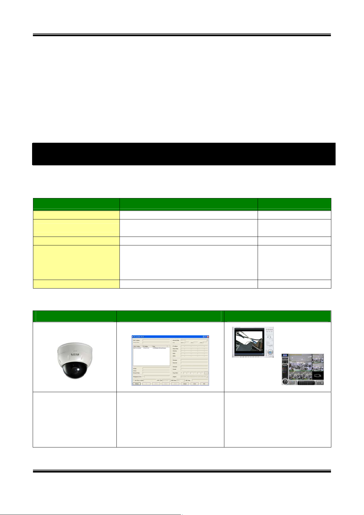
2.2. Preview
XNET IP-Installer XNET-NVR
Input: 100~250V 50-60Hz
Output: DC 12V, 3.33A
Cable for analog video output from
camera module inside of network
camera
Standard Power
Use your hand held
video monitor for
easy camera field
of view setup.
PC software to view and record
MPEG-4 Network Dome
Camera
5 of 44
PC software to assign an IP
address to the XNET
the A/V streaming data
transmitted from the XNET.
There are two editions available
(NVR/XNVR).
Page 6
XNET Network Dome Camera User’s Guide
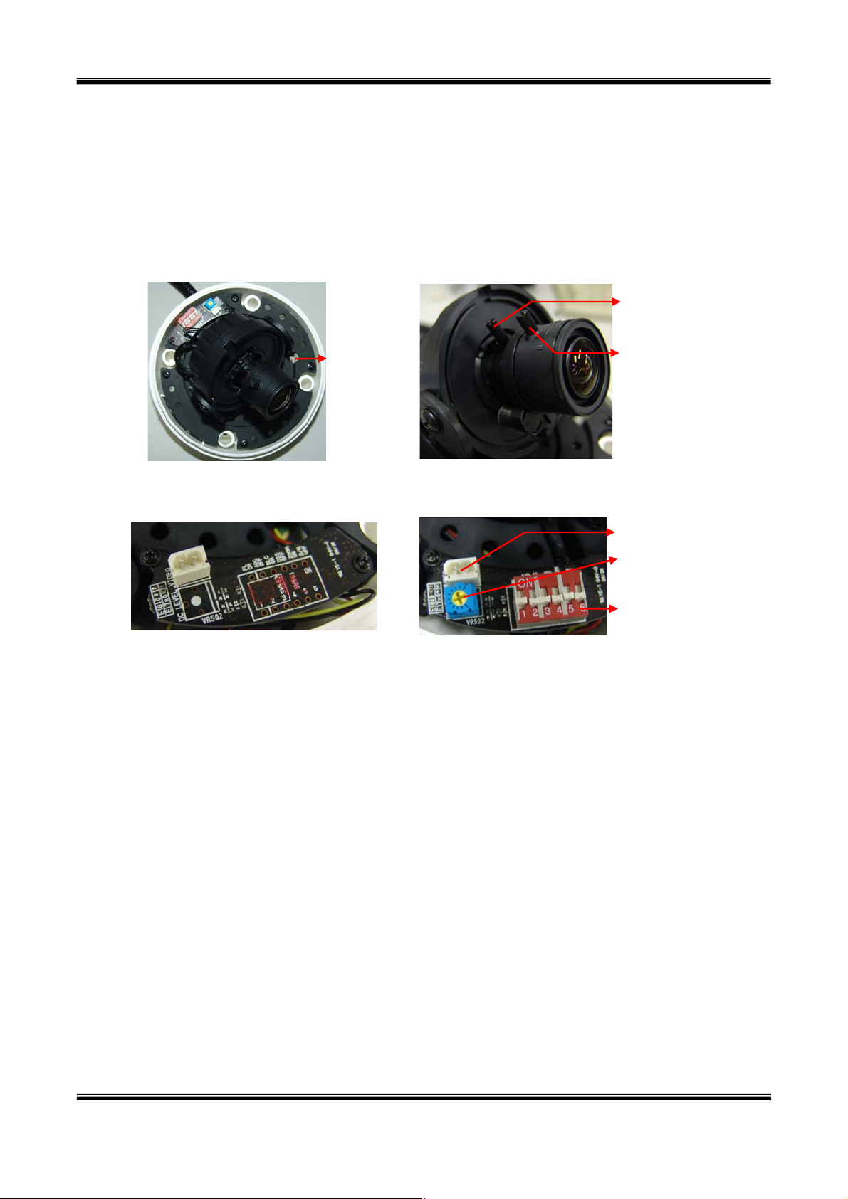
2.3. Physical description
2.3.1. Configuration DIP Switches
Depending on which model you purchased, the XNET network dome camera comes with one of
two optional modules (fixed focal type or vari-focal type).
Figure 2-1 illustrates exterior view and internal parts. Accommodating various camera site
requirements, the camera module can be configured to enable/disable various video features.
Zoom Control
a. Reset b. Control knobs for va ri-focal lens
C. Camera control Module for
fixed focal lens
Figure 2-1. External and inner views of XNET
Reset
Focus Control
Video out
DC Level
FL/AGC/BLC/
DSS/ZOOM/D&N
Switch
d. Camera control Module for
varifocal lens
y BLC (Back Light Compensation)
Under severe bright “back light” conditions, the target object w ill show dark, which hides
object detail. Set this switch to “ON” for compensation for this phenomenon. The target
object should appear with more detail after enabling this setting.
y AGC (Automatic Gain Control)
Set this switch to “ON” to enable this automatic video gain adjustment. Under
severe/excessive illumination conditions, the camera video may saturate. Enabling this
feature will automatically lower the video amplifier gain, improving video quality. This
setting also compensates for low light conditions. If the camera is subject to under
exposure, or overly dark illumination conditions, the camera will automatically increase
video amplifier gain, improving video quality.
6 of 44
Page 7
XNET Network Dome Camera User’s Guide
y FL or F/L (Fickerless)
Set this switch to “ON” to prevent flicker from the follow ing AC Power conditions:
- Using an NTSC camera in a region with 50 Hz AC power, or a PAL
camera in a region with 60 Hz AC power may cause a visible “video
flicker.”
This is outside of normal power conditions for the two aforementioned video standards.
Thus the improper 10 Hz differentiation is the cause of the “flicker.”
y D/N (Day & Night) - Available only for Day & Night camera module
Set this switch to “ON” to enable the camera’s day & night feature set. Under very low
light conditions, the camera automatically switches to “Nigh t Mode/Black an d White M ode,”
delivering daylight quality Black & White video.
y DSS (Digital Slow Shutter) - Available only for Day & Night camera module
Turning this switch “ON”, tells the camera to sacrifice the video refresh rate in order to
compensate for ultra low light conditions, improving th e brightness and sharpness of the
video.
y ZOOM (Digital Zoom) - Available only for Day & Night camera module
Set switch to “ON” to enable digital zoom.
y DC Level - Available only for Day & Night camera module
For adjusting output video DC levels.
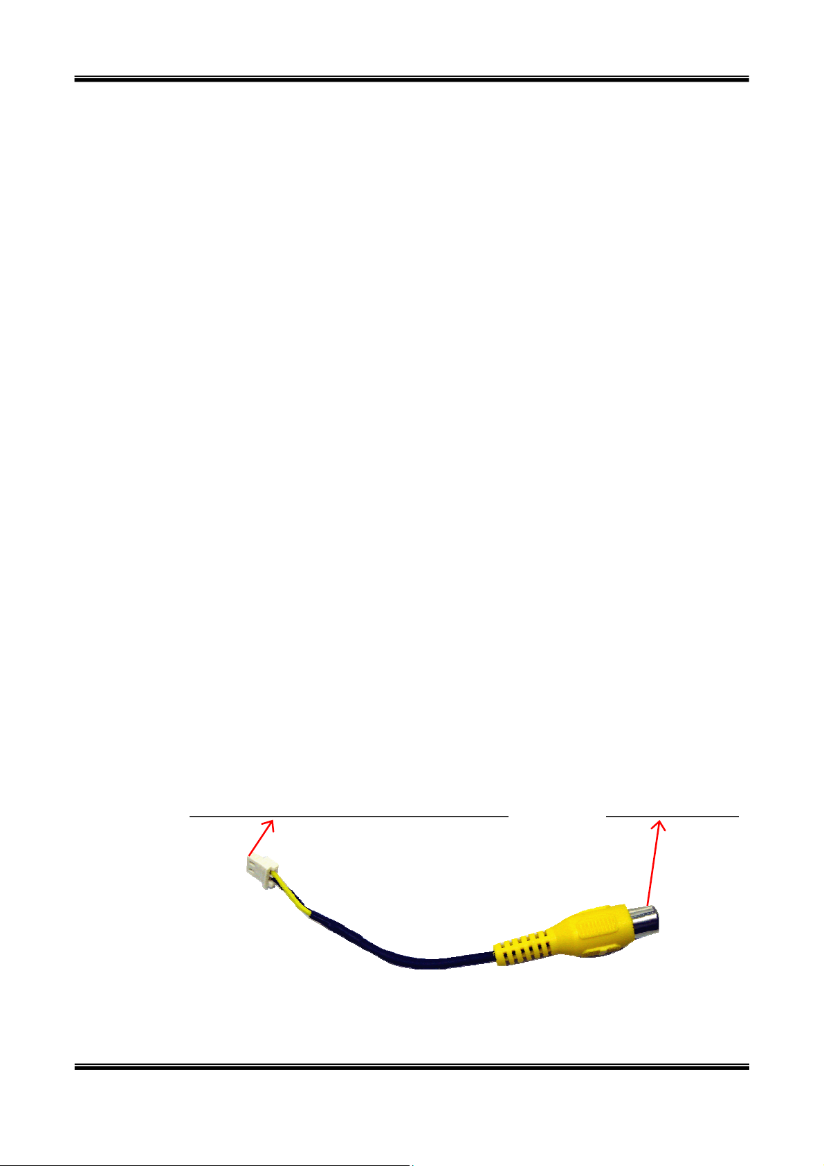
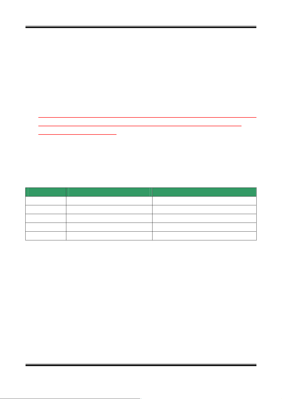
y Analog Video Output
Connect a handheld monitor to assist in adjust the viewing angle and focus right at the
camera.
A standard RCA video cable adapter is included with network camera.
To Analog Video Out of network camera To Analog Monitor
Figure 2-2. Analog Video Cable
7 of 44
Page 8
XNET Network Dome Camera User’s Guide
y Reset
There is a factory default switch provided for returning the network camera to factory
default state. Press the s witch using tools with sharp tip for a few seconds while power is
applied.
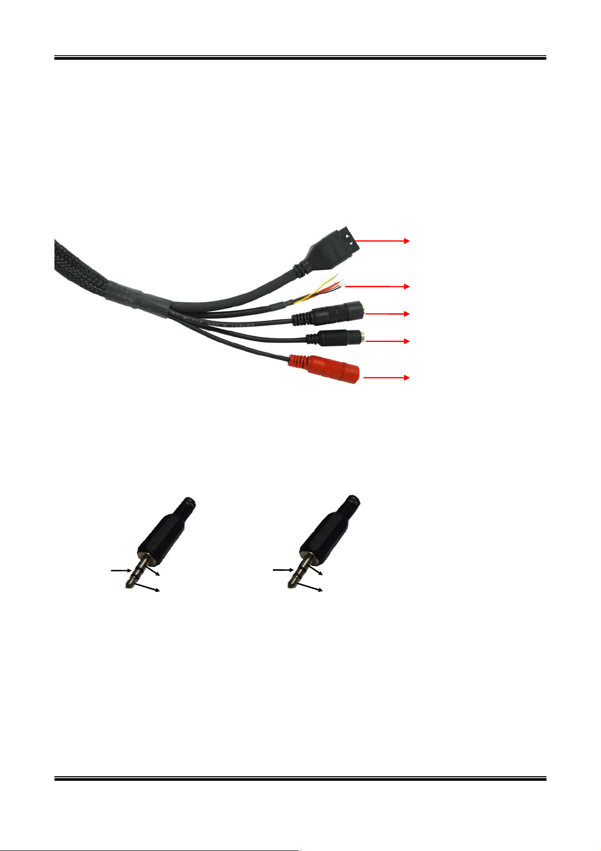
2.3.2. Bottom view and Cable Harness
100BaseT(RJ45)
Sensor In/Relay Out
Line Out
DC Power
MIC/Line In
Figure 2-3. XNET Cable
y MIC /LINE In
Connect external audio source or microphones here.
Use a standard stereo earphone jack for the connections.
Not used
Not used
Not used
Ground
Ground
Audio In
Audio In
Not used
Ground
Ground
Audio out
Audio out
Figure 2-4. Pin assignment of the plug for MIC/LINE In (left) and
LINE OUT (right)
y Line Out
Connect to speakers with built in amplifier, or PA system. Audio from the remote site is
output through Line out in bi-directional audio mode. Use a standard stereo jack for the
connection.
8 of 44
Page 9
XNET Network Dome Camera User’s Guide
y 100BaseT (RJ45)
100Mbps Ethernet connector (RJ-45) with proprietary PoE.
- Link LED: Continuous yellow light means that network cable is plugged in. It will
flicker when there is traffic.
- Status LED: Green color indicates that the camera is in normal operation mode,
while RED color indicates that the camera is in abnormal condition.
y DC Power
Power input o f XNET. DC 12V
<Warning>: Do not a pply power t hrough th e power input jack on the back of the
camera when power is supplied through a LAN cable using proprietary PoE.
This will damage the camera! CNBTEC assumes no responsibility for the damages
caused by applying power using both connectors.
y Sensor In/Relay Out
Used for connecting sensor, and alarm devices to XNET. Note that the each signal is
differentiated by color of cable.
Cable color Description Misc.
Red Sensor In (+) NC/NO selectable in admin mode.
Black Sensor In (-) NC/NO selectable in admin mode.
Orange Relay out Normal close
Brown Relay out Common
Yellow Relay out Normal open
Sensor Input : Connect external alarm sensors such as the infrared sensors, heat
sensor, magnetic sensors, etc. NC/NO selectable in the admin page.
Relay Output : It is used for connecting external alarm generators such as sirens,
flashing light, etc. When activated, relay output configures a closed circuit.
Please refer to Section 6.1 for more detailed description on the Sensor In and
Relay Out connections.
9 of 44
Page 10
XNET Network Dome Camera User’s Guide
2.4. PC Requirements
AV streaming data received from XNET can be decoded or stored in a PC running the XNETNVR program, which is a live monitoring and digital video recording PC compatible application.
Minimum PC requirements:
Minimum Recommended
CPU Pentium III 700 Pentium IV 1.2G above
Main Memory 128 MB 256MB above
Operating system
Web browser Internet Explorer 6.0 Internet Explorer 6.0
Resolution 1,024 X 768 Better than 1,024 X 768
Network 10 Base-T Ethernet 100 Base-T Ethernet
* Operating Systems supported : Windows 2000 Professional
*
Windows 2000 or XP Windows XP
Windows XP Professional / Windows XP Home Edition
2.5. Quick Installation Guide
This is a quick reference for experienced installers. For more detailed information please refer
to the installation manual and or the CNBTEC home page (
Download Center menu provides updates for Software, Firmware, and Manuals.
Registration is required.
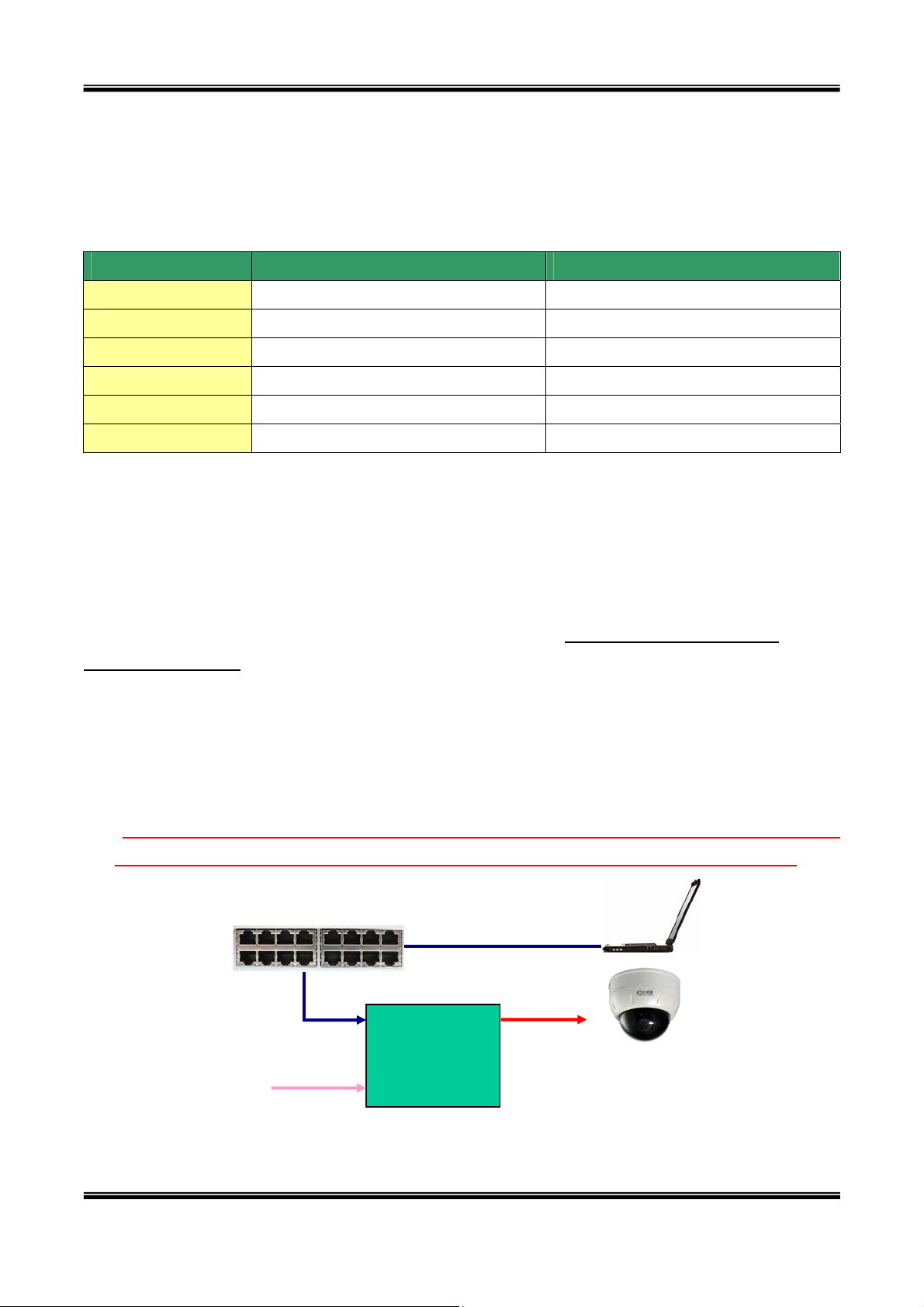
① Connect XNET to the LAN using one of the following methods
1) If you have PoE(Power Over Ethernet) Adaptor, connect the network camera and PC as
illustrated in Figure 2-5. The power and network connection are made using a single LAN
cable.
Note: CNBTEC cameras use proprietary PoE technology. Using a third party PoE
product with CNBTEC cameras will damage the camera and void the warranty.
http://www.cnbtec.com). The
LAN Hub
PC
100BaseT
LAN
PoE Adaptor
AC In
Figure 2-5. Connecting Network camera and PC using PoE Adaptor
10 of 44
Cam
XNET
Page 11
XNET Network Dome Camera User’s Guide
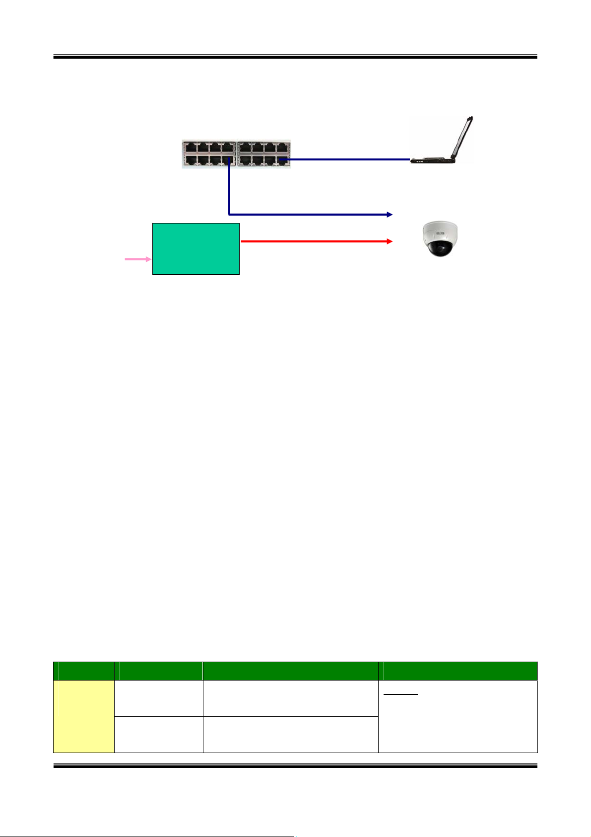
n
2) If you have standard power connect the network camera and PC as illustrated in
Figure 2-6.
LAN Hub
PC
100BaseT
DC I
AC Adaptor
AC In
XNET
Figure 2-6. Connecting Network camera and PC without using PoE
<Caution>: CNBTEC does not support standard PoE. Do not connect the
network camera directly to a hub supporting standard PoE.
② Apply power to XNET
③ Install “IP installer” and “XNET-NVR” on your PC.
Detailed information for installing these programs can be found in [IP-Installer User’s
Guide] and [XNET-NVR User’s Guide], respectively.
④ Assign IP address to XNET using IP installer.
Identify the type of the network environment and set up IP address. Detailed process of
setting up IP address can be found in [IP-Installer User’s Guide]. If network type is
xDSL or Cable modem you need supplementary information provided by your ISP.
⑤ Connect to XNET in Administrator Mode for initial parameter set-up.
The factory default state affords the ability to connect and configure the device in low
bandwidth environments. To configure the system for your environment use the
administration mode. Find detailed information for using administration mode in section 5:
Configuring XNET in Administrative Mode. The following set-up table briefly defines
setup parameters. For detailed information see: Section 5, Configuring XNET in
Administrative Mode]
[Note]: Set-up values are preserved even when the power is turned off.
Page Parameter Setup value Factory default value
Basic
Video Size
Setup
Max Upload
Rate
Sets transmit video resolution,
XNET.
Set this value smaller than the
uplink speed of your network.
NOTE: In order to “Save”
the values the user must
press the Check Button to
calculate the maximum
11 of 44
Page 12

XNET Network Dome Camera User’s Guide
Frame Rate
Video Rate
User
Administrator
Admin &
name &
Time
password
Setup
User
Admin &
Current Time
Time
Setup
⑥ Connecting input and output signals to the XNET.
Connectors Function Signal des c ription Number
Mic/LINE-In Audio in
The number of frames to be
transmitted per second.
Bandwidth assigned for video
transmitted from XNET.
For security reasons, CNBTEC
recommends changing these
values from the factory default.
Input correct time in this field.
Connect microphone or output from audio
devices.
number of simultaneous
users. Set the value smaller
than, or equal to calculated
Max value displayed
Default value
User name : root
Password : dw2001
Default value :
2001/1/1
1
Audio from remote site is available from
Line Out
Audio out for
speaker
Alarm Sensor Contact sensor, or Other Aux. Sensor 1
Sensor In
Alarm annunciating
/Relay Out
device, Aux Relay
100Base-T Network connection
DC Power Input DC Power to network camera 1
⑦ Remote video connection to XNET
Before attempting to connect and view video from the XNET, install XNET-NVR to
the PC. This will automatically install the ActiveX component needed for a direct
connection with IE Explorer. For more detailed information on using “XNET-NVR” see the
XNET-NVR User Guide.
this connector in bi-directional audio
mode. Connect an amplified speaker, or
PA device.
Siren, Flashing Light, Relay for Access
control device…
Connect XNET to the network, LAN, ADSL
or Cable modem.
1
1
1
12 of 44
Page 13
XNET Network Dome Camera User’s Guide
3. Connecting XNET to Network
XNET supports LAN, xDSL, and Cable modem. It also supports shared IP environments where
a single IP address is shared by two or more IP devices. Refer to [IP-Installer User’s Guide]
for details of setting the IP address for XNET.
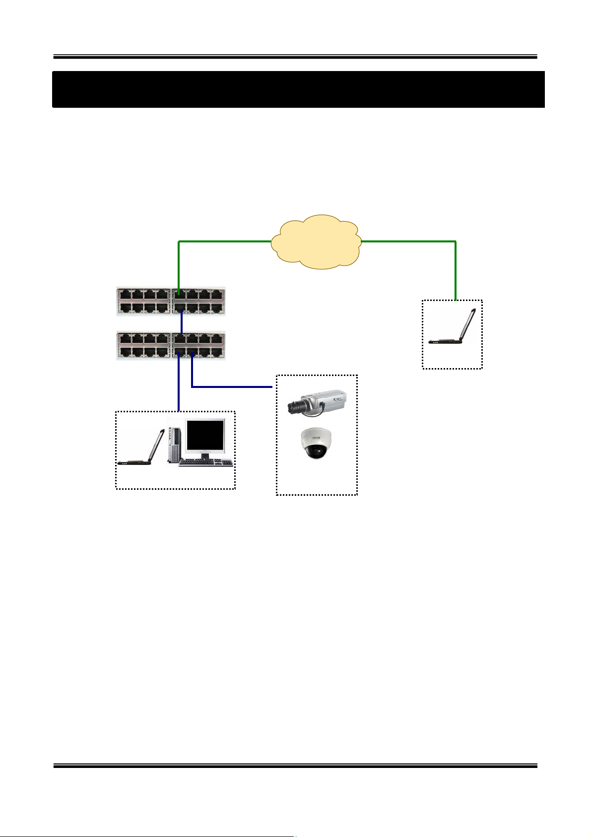
3.1. Connecting to LAN
IP Network
(LAN/WAN)
Router
Hub
Client PC
Figure 3-1. Connecting the XNET to LAN
1. Follow steps 1 through 4 in Section 2.5 to assign an IP address to the XNET.
2. Install XNET and connect to LAN.
XNET
Client PC
3. Test the ability to receive video data when connecting to XNET using XNET-NVR.
4. In order to access each unit from outside the local area network, each device must have a
unique RTSP (Real Time Stream Protocol) and HTTP port number. For example, when one or
more IP video products are connected through a IP sharing device (i.e. router) and then to a
larger network (i.e. the internet). The network administrator must also configure your IP
sharing device for “port forwarding”. This enables the IP sharing device to forward packet data
with unique port number (RTSP and HTTP) to the unique internal IP address (local IP address).
If you only plan to access multiple units from within a local area network, you do not need to
change the RTSP and HTTP port numbers, unless other IP sharing devices sit in-between the
client and the IP video products. For more detailed information regarding the use of IP sharing
13 of 44
Page 14
XNET Network Dome Camera User’s Guide
device, refer to the support document [Use of Private IP network using IP-sharing-
device] found on the Download Section of the CNBTEC web site.
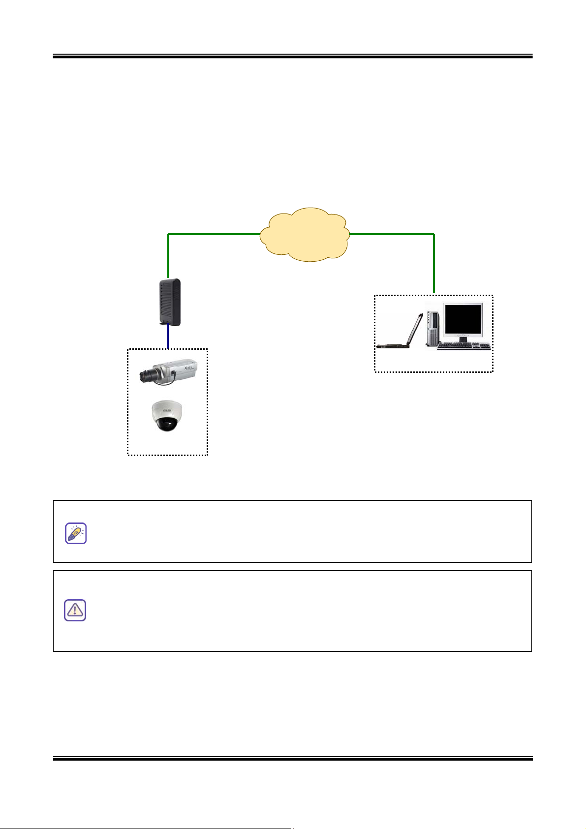
3.2. Connecting to an xDSL/Cable Modem
1. Follow through steps 1 through 4 in Section 2.5 to assign IP address and other network
parameters to XNET.
2. Install XNET and connect it to xDSL or Cable modem as in Figure 3-2.
IP Network
(LAN/WAN)
②
xDSL/
Cable
Modem
XNET
Figure 3-2. Connecting the XNET to ADSL/Cable Modem
When a static IP address is assigned to the xDSL or Cable modem, using IP-installer,
invoke the same method as “assigning an IP address on a LAN.” To enable email
notification of IP address changes assign a “send to” e-mail address using IP-installer.
Client PC
When connecting XNET/XNET-Wireless to xDSL or Cable modem, usually a
straight LAN cable is required. But since some modems have crossover
connections, in this case, you should use a crossover LAN cable. Please contact
your service provider for detailed information.
14 of 44
Page 15

XNET Network Dome Camera User’s Guide
4. IP-Installer
XNET/XNET-Wireless needs IP network parameters for connection to the network
(Internet/Intranet). IP-Installer is a PC program for the initial network configuration to IP video
products such as Network Camera or A/V Server. IP-Installer is provided in a CD supplied with
XNET/XNET-Wireless or it can be downloaded from “
Detailed information of Installing and running IP-installer can be found in [IPinstaller user’s guide]
4.1. Main window of IP-Installer
www.cnbtec.com”.
Figure 4-1. IP Installer
All the basic network parameters needed for the initial connection to IP video products can be
assigned by IP-Installer. Once the basic parameters are assigned and the initial connection is
successfully made, you can connect to the administration page for more sophisticated control of
the network parameters and other operational parameters. Refer to Chapter 5 for more details
of the administration page.
5. Configuring XNET in Administrative Mode
5.1. Log On
There are two ways of connecting to XNET/XNET-Wireless administrative mode. One is through
Internet Explorer (IE) and the other is through “XNET-NVR” or “XNET-XNVR” program. But
this user’s guide will explain accessing by IE and “XNET-NVR” only. (Please refer to the XNVR
user’s guide in the supplied CD for using “XNET-XNVR”.)
15 of 44
Page 16

XNET Network Dome Camera User’s Guide
5.1.1. Log on from Internet Explorer
The URL of the XNET administrative mode is as followings:
http://[Allocated IP address]/admin.htm
Example: http://172.16.64.133/admin.htm
If you changed the HTTP port from default value you can login by typing in:
http://[XNET/XNET-Wireless IP address]:[HTTP port]/admin.htm
Example: http://172.16.64.133:8080/admin.htm
5.1.2. Log on from “XNET-NVR”
Select video channel in the viewing window of “XNET-NVR”. Selected video channel will be
highlighted. Click
Figure 5-1. Log on to administrative mode from “XNET-NVR”
5.1.3. Input User Name and Password
After fallowing the method which explained in Section 5.1.1. or 5.1.2, the login screen will open.
button on the right side of the display screen.
Input the User Name and Password in the login screen shown in Figure 5-2.
16 of 44
Page 17

XNET Network Dome Camera User’s Guide
Figure 5-2. Login screen
The default setting for the User Name and Password are ‘root’ and ‘dw2001’, respectively. Click on
“OK” button to enter into the Basic Setup page of Administrative Mode. If you have changed the
username and password of the Administrator, you must log on with the changed username and
password.
After login to the administrative mode, change the user name and password for
security. Please refer to section 5.6. “User Admin & Time Setup” for detailed
information.
If you forget the user name and password, the only way to reset it is by resetting the
unit to factory default through the reset button. It will make all the set tings go back
to default. In this case, you have to setup the network parameters again. Please refer
to section 3.
17 of 44
Page 18

XNET Network Dome Camera User’s Guide
5.2. Basic Setup
Setup the basic parameters of the XNET/XNET-Wireless.
Figure 5-3. Basic Setup
Field/Button
Language
System Name
Screen Capture
in Web Viewer
Sub Field
/Button
Description
Select a language of your choice. English, Korean, Chinese,
Japanese, Spanish, Italian, Portuguese are available.
Logical name of the XNET. It is same as the one set-up by IPinstaller. You can reassign the system name.
Save a image file captured from the web viewer to the folder of
your choice. The file name format is as fallows
Capture_year_month_day_minute_second.bmp.
18 of 44
Page 19

XNET Network Dome Camera User’s Guide
Audio Input
Selection
Select the type of input audio.
Input Video This filed is set by the factory
Select a video size for transmission-
Video Size
Select the imaging method when the video resolution is Full D1.
Interpolation/
De-Interlace
Max. upload
rate
Assign maximum bandwidth of the uplink for the network
connected to XNET/XNET-Wireless.
Assign number of video frames to be transmitted for each second.
Select Line In for using Line-out from audio devices.
Select Mic for using microphone.
z NTSC(30 fps Max.): 720x480, 352x240, 176x144
z PAL/SECAM (25 fps Max.): 720x576, 352x288, 176x144
z Interpolation: Filtering not used. Provides clear images than
De-Interlace method, but a jaggy image will appear to the
moving object.
z De-Interlace: Using filtering. Proper to the moving objects,
but not clearer than Interpolation method.
Video Quality &
Bandwidth
Control
Frame rate
Video rate Assign bandwidth for transmitting video data.
Audio rate
Check
Possible Max
Users
Remained
Limited users
You can improve picture quality by lowering frame rate for the
same bandwidth.
Assign bandwidth for transmitting audio data. Audio data is not
transmitted if you select “NA”
After you finish set up of video and audio for all the channels, click
on this box to obtain the possible maximum number of users
(Possible Max Users) and remaining network bandwidth
(Remained) remaining when possible maximum users are
connected.
It shows the number of maximum simultaneous connections for
the network connection set-up.
It shows the network bandwidth remaining when Possible Max
Users are connected.
Useful network bandwidth varies according to the condition of the
network. This parameter is used to limit the number of the
simultaneous connections below the number shown in Possible
Max Users.
Save Save the set-up parameters when the set-up parameters are done.
19 of 44
Page 20

XNET Network Dome Camera User’s Guide
5.3. Network Configuration
Setup the network parameters appropriately in accordance with your network environment.
Many of the parameters in this page are same as those set up by “IP-Installer”.
Figure 5-4. Network Configuration
20 of 44
Page 21

XNET Network Dome Camera User’s Guide
Field/Button
IP Assign
Type
Sub Field
/Button
Static IP
Setup
PPPoE Setup
DHCP Setup
Description
The network types supported by the XNET/XNET-Wireless are
LAN(fixed IP), PPPoE, and DHCP(automatic IP allocation)
When the network environment is fixed IP, select ‘LAN’ in the
network type, and put the IP address, Subnet Mask,
Gateway, DNS1 and DNS2. Ask your network administrator
or ISP for the information. DNS2 is used when DNS1 does
not work.
When the network environment is PPPoE and IP address is
assigned automatically, select ‘PPPoE’ in the network type.
Next, fill in the ‘User Name’ and ‘Password’ fields with the
values assigned by the ISP.
When the network environment is “automatic IP allocation by
DHCP”, select ‘DHCP’ in the network type. For cable modem
connection, select this mode.
Refer to [IP-installer user’s guide] for “Host name and
Port Change
IP Filtering
domain for Cable Modem
Clone MAC Refer to [IP-installer user’s guide] for “Clone MAC”
Each port should have a number below 65,535.
RTSP
HTTP
Restrict
Administrator
Access
Base IP
Address
The RTSP port is used for transmitting real time audio/video
data from the network camera. Default is 554.
HTTP port is used for the connection to the admin page.
Default is 80.
You can restrict the access to the administrator page from IP
addresses beyond certain IP address range.
Check at this box to restrict administrative log on.
Input IP address of the PC which is intended to be used for
log on to administrative mode.
This is same as subnet mask. It is used to allow
administrative log on only to the PCs located in the same
Mask
E-Mail Setup
Notify for IP
Change
21 of 44
subnet as the base IP address. If you want to allow only one
PC to access in administrative mode, set this value to
255.255.255.255.
If you check this, the IP address will be sent via E-mail
whenever the IP address changes. It is sent to the E-mail
Page 22

XNET Network Dome Camera User’s Guide
address set by “Recv E-Mail Address”.
FTP Server
Setup
Recv E-Mail
Address
Return E-Mail
Address
Using Built-in
SMTP Server
Using
External
SMTP Server
Enter E-mail address to receive information sent from your
network camera. This is same as E-mail field in IP-installer.
Fill in this field with correct e-mail address to identify the
mail sent from the network camera
If you are using web mail services having no SMTP server,
check the radio button at the left of “Using Built-in SMTP
Server” and enter valid e-mail address to avoid spam
filtering on the receiving e-mail server.
If you are using external mail server, fill in the fields with
proper parameters.
Setup IP address, Username, Password and Directory of FTP
server to send data in case of alarm. Default FTP port
number is 21.
You can register the network camera to the Management
Server (DDNS Server) for name service to your network
camera.
Management
Server
Save
Log on to
server
Check this box to enable log on to the management server.
By log on to the management server your network camera
can use domain name instead of numeric IP address. This
feature is particularly useful when your network camera is
using dynamic IP address. Input valid management server
(DDNS Server) name for the service.
You must have an account on the management server
(
http://mgmt.ipdvrfree.com/) and register your IP video
devices under your account to use this feature.
Domain name of your network camera can be assigned when
you register your network camera to the management server
under your account.
Save the set-up parameters when the set-up parameters are
done.
22 of 44
Page 23

XNET Network Dome Camera User’s Guide
5.4. User Admin & Time Setup
You can change the ID and password of users and also assign different attributes for each user.
Figure 5-5. User Admin. & Time Setup
Field/Button
Administration
23 of 44
Sub Field
/Button
Administrator
Username
Administrator
password
Description
Admin ID. Default ID is “root” User
Admin password. The default password is “dw2001”.
Page 24

XNET Network Dome Camera User’s Guide
Administrator
Confirm
Password
Add User
Username
Add User
Password
Add User
Attribute
User List
Enter the password once more to confirm the password.
Enter the user ID you want to add. Up to 100 users are
supported by XNET/XNET-Wireless.
Enter the user password.
You can set different system resource access capabilities for
each of the users. Attributes are Audio, Bi-directional Audio
and Pan/Tilt control. For example, if you want a specified
user to hear the audio from the XNET/XNET-Wireless, check
Audio in the check box.
You can list “user ids” and “ their attributes” here.
format : user id[A, BA, P] :
A – audio,
B – bi-directional audio,
P – ptz(Pan/Tilt), not used for this model.
Authentication
for Viewing
YES
SAVE
If no, default
attribute
You can delete specific user by clicking the DELETE button.
If you want to restrict viewing access to the XNET/XNETWireless, check at the box left to Yes and click on Save.
Users need to input ID and password to connect to
XNET/XNET-Wireless. The a pop up window as shown below..
Figure 5-6. User authentication pop up
If the username or password are incorrect, an error message
will be displayed
If you uncheck for the Authentication for Viewing, all users
can access the XNET/XNET-Wireless with the same attribute
set here. Checked attributes are enabled. Click “Save” to
save the attribute.
Time Setup Current Time It shows you the current time of XNET/XNET-Wireless.
24 of 44
Page 25

XNET Network Dome Camera User’s Guide
Synchronize
with an
Internet
Time Server
Synchronize
With this
Computer
Time
Set Manually Set the time manually. Fill in the fields with desired formats.
SAVE Save the set up parameters
If you lost Administrator’s ID and password, the only means of recovery is to
reset the settings to factory default, but then you lose your previous settings.
Synchronize the time with the internet time server at the
right. When the time server is out of the reach from
XNET/XNET-Wireless, you can assign time server by filling in
Specific Time Server field.
Synchronize the time with the time of the PC.
25 of 44
Page 26

XNET Network Dome Camera User’s Guide
5.5. Sensor & Capture Setup
This is the setup page for sensors and video capture conditions. Captured video can be sent to
user by FTP or E-mail upon configuration.
Field/Button
Video Capture
Condition
Figure 5-7. Sensor & Capture Setup
Sub Field
/Button
Sensor 1
Name Input logical name for the sensor.
Sensor
Select
Motion
Detection
Select
Select sensor type. There are two types of sensors which are
Normal Open and Normal Close. Sensor Setup
It sets the condition of video transmission via FTP or E-mail.
The XNET/XNET-Wireless supports 2 types of conditions which
are mutually independent.
Check to enable Sensor initiated capture.
Check to enable motion detection initiated capture.
Description
Captured
Video
26 of 44
Select a way of sending captured video. You can send
captured video through FTP or E-mail, or both.
Page 27

XNET Network Dome Camera User’s Guide
Transmission
By E-Mail
By FTP
SAVE Save the setup parameters.
To prevent the client mail server's storage capacity excess, the system send only
video data (iframe data) to the client in the E-Mail mode. But in the FTP mode,
system sends all the data including the audio data and the full frame of video data. If
you want to transmit all the data, select the FTP transmission mode.
Check to send captured video by e-mail.
E-mail is sent to the Recv E-mail address.
Refer to [Section 5.3.]
Captured video data for E-mail consists of intra frames only in
consideration of the limited storage space for E-mail account.
FTP data contains entire video frames.
Check to send captured video by FTP.
FTP is sent to the FTP Server. Refer to [Section 5.3.]
If the FTP server is not properly assigned in “Network
Configuration” mode, XNET/XNET-Wireless ignores the
video transmission by FTP
When the FTP server or email address is invalid, the transmission process will be
discarded
27 of 44
Page 28

XNET Network Dome Camera User’s Guide
5.6. Alarm Device Setup
Test the alarm output and describe the condition of alarm annunciation.
Figure 5-8. Alarm Output Setup
Field/Button
Alarm Device
Test
Sound Test Used for audio/voice testing
Alarm Device
Active
Condition
Sub Field
/Button
Test alarm devices. Click on On/Off for testing.
ON On the alarm output (close the relay contact)
OFF Off the alarm output (Open the relay contact)
Name
Sensor
Motion
Small box with white background indicates the status of the
relay by On/Off.
Setup the condition of activating alarm device. Select sensor
or motion detection as the condition.
Logical name of the alarm device can be input into the box at
the left.
Check at the box at the left of to allow alarm generation upon
sensor input.
Check at the box at the left to allow alarm generation upon
Motion detection
Description
Duration
Set the duration of Alarm annunciation.
10/30 sec, 1/2/5/10/30 min, 1 hour.
SAVE Save the setup parameters.
28 of 44
Page 29

XNET Network Dome Camera User’s Guide
5.7. Motion Region Setup
Set the motion detection regions. Up to 3 regions can be defined.
Figure 5-9. Motion Region Setup
Field/Button
Channel
Selection
Channel
Sensitivity
29 of 44
Sub Field
Description
/Button
Not applicable.
Set the sensitivity in motion detection for each ch annel. 1 is
the most sensitive, and 10 is the least sensitive.
Page 30

XNET Network Dome Camera User’s Guide
Set up to 3 the motion detection zone
Enable each zone by checking the box at the left of each
Region.
To set the region:
Motion Region
Setup
SAVE Save the setup parameters.
Region 1, 2,
Click on START and click on a box overlaid on the video
Click on END and click on a box overlaid on the video.
or 3
The defined motion detection zone will be indicated with
corresponding colors.
Legend of the color:
Region 1: red, Region 2: green, Region3: blue.
START Enable selection of rectangular zone start.
END Enable selection of rectangular zone end.
Click on this button and click on desired rectangle to add or
SELECT
delete the rectangular region to the motion detection zone.
This value controls the sensitivity of each region.
Percentage
1 is the most sensitive and 100 is the least sensitive
RESET Clears the start & end point to (0,0) & (0,0)
30 of 44
Page 31

XNET Network Dome Camera User’s Guide
5.8. PTZ Setup (This is not related with XNET Network Dome Camera)
Setup and test the PT(Pan/Tilt) devices.
Sub Field
Field/Button
/Button
Channel
Selection
PTZ Model
Delete
Selection
PTZ Device ID
Figure 5-10. PTZ Setup
Description
Not applicable
Choose the PT model.
Press this button to delete the setup of PT
Button
Your PT device needs an ID, input ID in this field.
Click on SAVE to save the ID.
31 of 44
Page 32

XNET Network Dome Camera User’s Guide
Note that zoom is not applicable for XNET
PTZ
Operation
Check
PTZ Position
Setup
Panning
Limitation
Panning
Limitation
RESET
Panning
Limitation
SET
Panning
Limitation
TEST
Preset
Position
You can check the various operation of the PT devices.
z “Left”/”Right”/”UP”/”DOWN”
z ZIN(Zoom In), AUTOFOCUS, ZOUT(Zoom Out)
functions does not applicable to this product
You can set up the PTZ limitation & preset positions if the PT
device supports it.
Set the left/right limitation and test.
Select Left/Right position before setting.
Clear the panning limitation previously set .
The panning range will be the same as the PT device allows.
Set the present position as left or right panning limitation.
Test the panning limitation which was set previously.
Set the preset position and test.
Preset
Position
Preset &
Move
Preset
Position
Name Set
Preset
Position
Set
<Note> : “PTZ Position Setup” feature is applicable only for the PT devices that support it.
Select a preset position to move to. Movement to the preset
position will be made upon clicking on “MOVE”
Assign logical name for the preset position. Enter into the field
and click on SET.
Set the present position as a preset position with position
number shown at the right of “Preset & Move” and name
shown at the right of “Name Set”.
32 of 44
Page 33

XNET Network Dome Camera User’s Guide
5.9. Encryption Set up
Figure 5-13. Encryption Setup
For additional security to the video and audio data transmitted from the network camera, you
can set key codes and use them for encrypting the data from the network camera.
You can selectively activate encryption for the video and audio data. For enabling the encryption,
check at the box at the left of the “Enable data encryption” then check at the proper check
boxes at the left of “Video” and “Audio”. After t he selection, click on SAVE button beneath the
“Video” and “Audio” check boxes.
Field/Button
Enable Data
Encryption
Sub Field
/Button
Check at this box to apply data encryption.
Video Check to enable encryption on the video data.
If it is unchecked encryption is applied on neither video nor
audio data regardless of the selection below.
Description
Audio Check to enable encryption on the audio data.
SAVE After the selection, click on SAVE button.
33 of 44
Page 34

XNET Network Dome Camera User’s Guide
Key Value
GENERATE
SAVE
DOWNLOAD
INSTALL
You can use up to 20 different key codes for the encryption
of the data
To generate the key value click on “GENERATE” button. The
boxes for the Key values will be filled with new values.
Save Key value on the network camera: Click on SAVE
button beneath GENERATE button to save the key value
generated by the network camera.
Download Key value to your PC: The key values can be
downloaded and stored as a file to your PC for reference
when you make connection. When encryption is enabled,
the PC client program will ask for particular key value out
of the 20 available key values. The downloaded file name
format is key_value.rtf
Upload key value to the network camera: The key
value stored on your PC can be uploaded to your network
camera. This feature is useful when you manage multiple
network cameras having same key value sets. Select a file
having key values then click on “INSTALL” button to upload
the key values.
34 of 44
Page 35

XNET Network Dome Camera User’s Guide
5.10. Upgrade & Reset
You can upgrade the XNET/XNET-Wireless via the IP network.
Figure 5-14. Upgrade & Reset
For each of the upgrade of the system component, upgrade code should be downloaded from
cnbtec’s home page before the system upgrade is performed.
(Refer to [6.4.
Field/Button
Automatic
Upgrade
How to Upgrade Your XNET/XNET-Wireless System]
Sub Field
Description
/Button
Automatic upgrade is a feature that enables network
camera to upgrade to newly released system software by
automatically connecting to upgrade server. Click on check
button to find the availability of upgrade firmware.
Note that automatic upgrade is not supported for this
product.
Upgrade the system manually. Manual
Upgrade
System S /W
Upgrade
35 of 44
Upgrade the system software installed in the network
camera via the network. System software needed for the
upgrade can be downloaded from cnbtec’s home page.
Page 36

XNET Network Dome Camera User’s Guide
Refer to [6.4. How To Upgrade Your XNET/XNET-
Bootloader
Upgrade
Add PTZ File
Factory
Default
Setting
Wireless System]
Upgrade the bootloader installed in the network camera via
the network. Bootloader needed for the upgrade can be
downloaded from cnbtec’s home page.
Refer to [6.4.
Wireless System]
Add a new PT driver software via the network. PT driver
can be downloaded from cnbtec’s home page.
Refer to [6.4. How To Upgrade Your XNET/XNET-
Wireless System]
Re-initialize the network camera to factory default state.
By checking on a Radio button “Except Network
Configuration”, you can preserve the parameters for the
network. Checking on “All”, will return all the parameters to
factory default state.
Once XNET/XNET-Wireless is re-initialized as factory
default state, it should be set-up again using IP-
.
How To Upgrade Your XNET/XNET-
.
.
System Reset
Installer.
Perform remote reset by clicking the “CONFIRM” button.
All previous connections will be disconnected upon
reset. XNET/XNET-Wireless does not resume the
connections and the users must re-connect to the
server manually.
36 of 44
Page 37

XNET Network Dome Camera User’s Guide
5.11. Status Report
It shows you system records since the system started.
You can check the problems as well as the versions and event status of the whole system and
each module.
Figure 5-15. Status Report
37 of 44
Page 38

XNET Network Dome Camera User’s Guide
6. Tips for Using XNET
6.1. Sensor-IN and Relay-OUT
Use the Sensor-In and Relay-Out Cable to connect various sensing and alerting devices.
Examples of sensing devices are infrared sensors, motion sensors, heat/smoke sensors,
magnetic contact sensors, etc. Use the *Relay-Out connector for connecting device such as
loud speakers, flashing lights, or access control devices. * Make sure to follow the
recommended current limitations for this relay (AC/DC 30V @ 1 amp). An auxiliary relay may
be needed.
Cable color Description Misc.
Red Sensor In (-) NC/NO selectable in admin mode.
Black Sensor In (+) NC/NO selectable in admin mode.
Orange Relay out Normal close
Brown Relay out Common
Yellow Relay out Normal open
Figure 6-1. ALARM-IN/ALARM-OUT Cable
6.1.1. ALARM-IN
Connect the two wires of the sensors to “Alarm In”. The sensor type can be set in Administrative
mode. Output lines providing on-off switch ing are connected between “+“ and “-” pins. Figure
6-2 shows the input circuit of “Alarm In”.
Figure 6-2. ALARM-IN circuit
38 of 44
Page 39

XNET Network Dome Camera User’s Guide
6.1.2. ALARM-OUT
A Relay output is provided for connecting alarm devices or for remote on/off devices such as
light control. Relay circuits are normal open and circuits are closed upon alarm output or remote
on. The relay is capable of switching AC/DC 30V,1A electrical signal.
Figure 6-3. ALARM-OUT circuit
39 of 44
Page 40

XNET Network Dome Camera User’s Guide
6.1.3. Connection of Sensor, Alarm Device
6.1.3.1 Connection of Sensor
Photo Coupler
+12V
6.1.3.2. Connection of Relay
GND
Relay Switch Power Supply
Sensor1+
Sensor1-
1V~30VDC /AC,1A
NO/NCType
Sensor
Device
Sensor
Power
Supply
Open CollectorType
Sensor
Device
Sensor
Power
Supply
Alarm
Out
Device
Power
Supply
(30V
~)
Optional
Relay Switch
Alarm
Out
Device
Power
Supply
(1~30
VDC/AC,1A )
Relay
Relay1
-
+
Relay1
You can use the supported relay output to directly drive a maximum load of 30V
AC/DC at 1A. By connecting additionally relay circuitry (such as optional relay
switch), it can also drive heavier loads.
40 of 44
Page 41

XNET Network Dome Camera User’s Guide
6.2. Trouble Shooting
6.2.1. After XNET/XNET-Wireless is successfully installed.
•
XNET/XNET-Wireless in viewing mode, neither channel name nor video is display
and eventually timeout message is shown up.
Ö Check the power and network connection of XNET/XNET-Wireless.
To check if the network is properly operating, open the browser and try to connect to any
server: Example)
or open the MS-DOS Prompt and type the following: Example) ping
Then press Enter. If you see the “Repl y from …” message it means that the network is
working properly.
To check if the XNET/XNET-Wireless is connected, open the MS-DOS Prompt and type the
following.
ping [the IP of the server]
Example) ping 192.168.1.112
If you see the “Reply from …” message, it means that the server is properly connected.
If you do not see a Reply message, check if the network cable and power cable are
properly connected.
6.2.2. After Successfully Connecting to the XNET/XNET-Wireless
•
Video movement is slow.
Ö In Basic Setup of Admin Mode, lower the “Quality”. High quality means more data. You
can also set the “Max. upload rate” to higher value. But this value must be lower than
the maximum upload speed of your network. For example, if the maximum uploading
http://www.yahoo.com
www.yahoo.com
bandwidth of the network is 400Kbps, set the total “Max. upload rate” as 384Kbps. If you
set it higher, the video image can be corrupted with artifacts.
Ask your network manager or ISP for maximum uploading bandwidth of the network.
•
The image is dull and I see green, pink dots.
Ö This could be caused by performance limitation of the PC. Do not run too many programs
while running viewer program. The other reason could be missing data while
transmission from XNET/XNET-Wireless.
•
Mosaic phenomenon.
Mosaic phenomenon occurs when not enough network bandw idth is available considerin g th e
resolution and frame rate of the video.
Example is 704x480 video with low Max. upload rate.
Users are recommended to adjust resolution and frame rates to lower values for lower
bandwidth network.
41 of 44
Page 42

XNET Network Dome Camera User’s Guide
6.3. Web Viewer
XNET/XNET-Wireless is designed to be connected through internet explorer, too. For connection
to XNET/XNET-Wireless using internet explorer type in IP address or host address in the address
input field of the internet explorer.
Figure 6-4. Web Viewer of XNET/XNET-Wireless
42 of 44
Page 43

XNET Network Dome Camera User’s Guide
z Control Panel of Web Viewer
Enable bidirectional audio. When bidirectional
audio is enabled, voice from your PC is delivered
to XNET/XNET-Wireless.
Capture and store the still image on your desk
top screen.
Connect to XNET/XNET-Wireless in administrative
mode of XNET/XNET-Wireless.
Rotate the screen by 180 degree.
Connect to XNET/XNET-Wireless.
Stop the connection.
Contrast, Brightness, and Volume adjustment..
Check the box to mute the audio.
Adjust the size of the screen. Normal (x1), Twice
(x2), Half (1/2), Full Screen (full)
On/off the relay by pressing the button
Shows the status of the sensor. Blue color means
that the sensor is in normal state, while red color
indicates alarm situation.
Number on the button indicates the number of
sensor.
Move the center of the camera in
up/down/left/right directions.
Not applicable for XNET/XNET-Wireless.
43 of 44
Page 44

XNET Network Dome Camera User’s Guide
6.4. How to Upgrade the XNET/XNET-Wireless
Unless otherwise instructed, the owners of the XNET/XNET-Wireless are recommended to
upgrade the system when upgraded firmware is released using manual upgrade procedure.
(The automatic upgrade mode will supported soon later.)
Followings are the procedure to apply for the automatic upgrade
1) Save the upgrade system software to your PC. Upgrade software can be downloaded
from cnbtec’s home page or provided in CD.
2) Log on to administrative mode and select “Update & Reset” menu.
3) Click "Browse..." to find the files you want to use for upgrade. This will open a "Choose
file" dialogue window. The file extension is “ief”.
4) When you've found the file, click "Open." This will select the file and close th e "Choose
file" dialogue window.
5) Click the "INSTALL" button. An alert message box will pop up. Click “OK” button then it
will start uploading the file. This may take some time.
6) Upgrade completion message will appear after the system upgrade has been completed.
7) Reboot XNET/XNET-Wireless by performing “System Reset”.
8) After rebooting, log on to the server in administrative mode again and click the “Status
Report”.
9) Check the version number and release date of the XNET/XNET-Wireless.
You can download the XNET system software from
CNBTEC’s homepage. http://www.cnbtec.com
44 of 44
 Loading...