

Page 1

USER GUIDE
4 Channel Digital Video Recorder
This document contains preliminary information and subject to change without notice.
Page 2
2
SAFETY PRECAUTIONS
This symbol is intended to alert the user to the presence of important
operation and maintenance (servicing) instructions in the literature
accompanying the appliance.
This symbol is intended to alert the user to the presence of
unprotected “dangerous voltage” within the product’s enclosure that
may be strong enough to cause a risk of electric shock persons.
DKS
EXPLANATION OF SYMBOLS
CAUTION
THIS PRODUCT HAS MULTIPLE-RATED VOLTAGES (100V AND 240V).
SEE INSTALLATION INSTRUCTIONS BEFORE CONNECTING TO THE POWER SUPPLY
THIS PRODUCT USES A LITHIUM BATTERY.
THERE IS A RISK OF EXPLOSION IF THE BATTERY ON THE MAIN BOARD IS REPLACED BY AN INCORRECT TYPE. DISPOSE
OF USED BATTERIES ACCORDING TO INSTRUCTIONS.
THIS EQUIPMENT AND ALL COMMUNICATION WIRINGS ARE INTENDED FOR INDOOR USE.
TO REDUCE THE RISK OF FIRE ELECTRIC SHOCK, DO NOT EXPOSE THE UNIT TO RAIN OR MOISTURE.
Page 3

3
WARNING
The product should be installed by a trained professional. The DVR should be powered off when connecting
camera, audio, or sensor cables.
The manufacturer is not responsible for any damages caused by improper use of the product or failure to
follow instructions for the product.
The manufacturer is not responsible for any problems caused by or resulting from the user physically
opening the DVR for examination or attempting to fix the unit. The manufacturer may not be held liable for
any issues with the unit if the warranty seal is removed.
Page 4
4
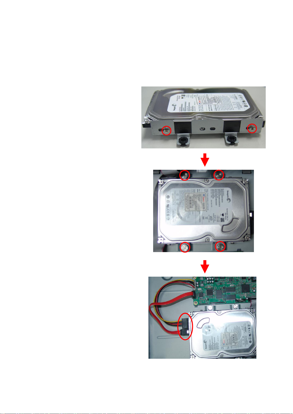
HDD INSTALLATION
Screw the HDD brackets to
the HDD and insert rubber rings.
Fix the HDD to the chassis.
Firmly insert SATA data cable and
power cable to the HDD.
Page 5
5
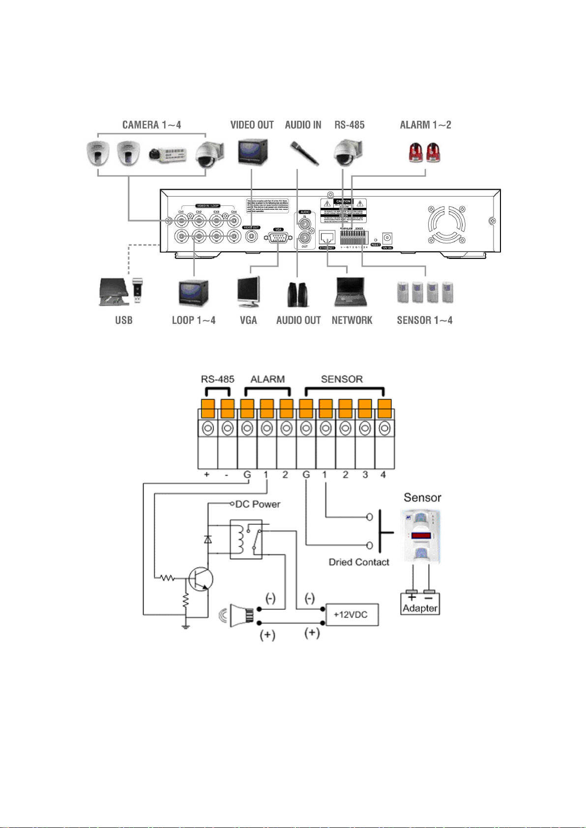
SYSTEM SCHEMETIC
Wiring Camera Control port and Sensor input / Alarm output
SENSOR INPUT: 5V TTL input. Connect two signal lines of sensor to the desired sensor number. (You can
set the type-NC or NO- of sensor at “Setup” mode).
ALARM OUTPUT: 5V TTL output. Connect two output lines of alarm to the desired alarm number (G and
1~2) after you set the circuit diagram like above
Page 6

6
TABLE OF CONTENTS
1. Introduction ..................................................................................................................................................... 9
1-1. The System .......................................................................................................................................... 9
1-2. General Features ................................................................................................................................. 9
1-3. Package Contents .............................................................................................................................. 10
2. Basic Operation ............................................................................................................................................ 11
2-1. Front Panel ......................................................................................................................................... 11
2-2. Rear Panel ......................................................................................................................................... 12
2-3. Start the System ................................................................................................................................. 13
2-4. Menu Bar ............................................................................................................................................ 13
2-5. Display Icons ...................................................................................................................................... 13
2-6. User or Admin Login ........................................................................................................................... 14
2-7. The Main Menu .................................................................................................................................. 14
2-8. Contextual Menu ................................................................................................................................ 14
3. DVR Configuration ........................................................................................................................................ 15
3-1. System ............................................................................................................................................... 15
3-1-1. MENU > SYSTEM > Information ............................................................................................. 15
3-1-2. MENU > SYSTEM > Data & Time ........................................................................................... 16
3-1-3. MENU > SYSTEM > Password ............................................................................................... 16
3-1-4. MENU > SYSTEM > Storage ................................................................................................... 17
3-1-5. MENU > SYSTEM > System Log ............................................................................................ 17
3-1-6. BACKUP .................................................................................................................................. 18
3-1-7. Clip Maker ................................................................................................................................ 19
3-2. Device ................................................................................................................................................ 20
3-2-1. MENU > DEVICE > Camera .................................................................................................... 20
3-2-2. MENU > DEVICE > PTZ .......................................................................................................... 20
3-2-3. MENU > DEVICE > Sensor & Motion ...................................................................................... 22
3-2-4. MENU > DEVICE > Alarm & Buzzer ........................................................................................ 22
3-3. Record ................................................................................................................................................ 23
3-3-1. MENU > RECORD > Record Setting ...................................................................................... 23
3-3-2. MENU > RECORD > Schedule ............................................................................................... 24
3-3-3. MENU > RECORD > Event ..................................................................................................... 25
3-4. Display ................................................................................................................................................ 26
3-4-1. MENU > DISPLAY > OSD ....................................................................................................... 26
3-4-2. MENU > DISPLAY > Monitor ................................................................................................... 26
3-5. Network .............................................................................................................................................. 27
Page 7

7
3-5-1. MENU > NETWORK > Address............................................................................................... 27
3-5-2. MENU > NETWORK > DDNS ................................................................................................. 28
4. Playback ....................................................................................................................................................... 29
4-1. Display ................................................................................................................................................ 29
4-2. Search Options................................................................................................................................... 29
4-2-1. Go to Time ............................................................................................................................... 29
4-2-2. Calendar Search ...................................................................................................................... 30
4-2-3. Event Search ........................................................................................................................... 30
4-2-4. Playback Control ...................................................................................................................... 31
5. Web Viewer .................................................................................................................................................. 32
5-1. Login ................................................................................................................................................... 32
5-2. Live ..................................................................................................................................................... 32
5-3. Playback ............................................................................................................................................. 33
5-3-1. Calendar Search ...................................................................................................................... 34
5-3-2. EVENT Search ........................................................................................................................ 34
6. HDxViewer .................................................................................................................................................... 35
6-1. Quick Start .......................................................................................................................................... 35
6-1-1. Live .......................................................................................................................................... 35
6-1-2. Search ...................................................................................................................................... 38
6-1-3. Setup ........................................................................................................................................ 39
6-2. Server list indication ........................................................................................................................... 41
6-3. Program shutdown, volume, PTZ control, server connection & disconnection ................................. 41
6-4. Screen division, full screen and switching ......................................................................................... 41
6-5. LCD window and log .......................................................................................................................... 42
6-6. Single channel player, network recording and preset ........................................................................ 42
6-7. Authentication ..................................................................................................................................... 43
6-8. Screen capture ................................................................................................................................... 43
6-9. Server list ........................................................................................................................................... 44
6-9-1. Server connection .................................................................................................................... 45
6-9-2. Server disconnection ............................................................................................................... 46
6-9-3. Connect all servers .................................................................................................................. 46
6-9-4. Watching video ........................................................................................................................ 47
6-9-5. Not watching video .................................................................................................................. 47
6-10. Server list use................................................................................................................................... 47
6-11. Single channel player ....................................................................................................................... 48
6-12. Preset ............................................................................................................................................... 48
Page 8

8
6-13. Setup ................................................................................................................................................ 48
6-13-1. Local setup............................................................................................................................. 49
6-13-2. Remote setup ........................................................................................................................ 49
6-14. Search .............................................................................................................................................. 49
6-15. Backup Viewer ................................................................................................................................. 50
6-16. Local Viewer ..................................................................................................................................... 51
APPENDIX ........................................................................................................................................................ 53
A-1. DDNS(Dynamic Domain Name Server) ............................................................................................ 53
A-1-1. Use DDNS service after signing up for autoipset.com ............................................................ 53
A-1-2.Use DDNS without signing up for autoipset.com ..................................................................... 56
A-2. Compatible HDD models ................................................................................................................... 57
A-3. Specifications ..................................................................................................................................... 58
Page 9

9
1. Introduction
1-1. The System
Thank you for purchasing the most reliable 4 channel DVR with high quality image. DVR provides better
compression than current other MPEG4 DVR and best image quality, smallest packet size, DVD quality video,
transmits video more efficiently over networks than any of previous technologies.
The DVR guarantees the most reliable security system ever introduced in the market. The DVR brings you
the most reliable and fully featured surveillance technology you have ever experienced. The latest official
H.264 video compression standard will lead you the new technology in CCTV.
1-2. General Features
• Embedded Linux System to Guarantee Maximum Reliability
• H.264 Video Compression Standard
• Max.120 (NTSC) / 100(PAL) ips Recording
• Supports D1 / Half D1 / CIF Resolution
• Multi Operational System: Display, Recording, Playback, Networking, Backup
• Dedicated DB System for Stability
• Offers Lower Bit Rates and Better Picture Quality
• Easy One Touch Backup
• Backup, Upgrade, Setup via USB and Network
• Superior Image Quality of H.264 in Low Bandwidth
• Interactive Setup for Easy Remote Control
• 4 Cameras In / 1 Audio In
• Supports SATA HDD
Page 10

10
1-3. Package Contents
The following components are included in the DVR package:
DVR SET
1. NETWORK CLIENT S/W CD
2. REMOTE CONTROLLER & BATTERY
3. MANUAL
4. ADAPTOR & POWER CABLE
5. RUBBER RINGS & SCREWS FOR HDD INSTALLATION
6. IDE HDD CABLE
7. HDD BRACKETS
Page 11
11
2. Basic Operation
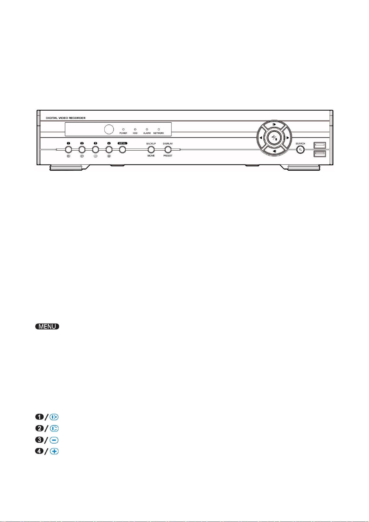
2-1. Front Panel
USB Port : USB ports on the front panel provides following functions:
i. Backup files using USB Flash Memory
ii. Control the system using an USB Mouse
iii. Save/Load the system settings using an USB Flash Memory.
LED Indication
Power LED: LED will be on when power is supplied to the system
HDD LED: LED will be on when data is being recorded or searched in HDD.
NETWORK LED: LED will be on when the system is being connected via network.
ALARM LED: LED will be on when the alarm is being activated.
Front panel buttons
: Press the „Menu‟ button to enter/exit the setup screen.
SEARCH: Press the „SEARCH‟ button to enter playback mode.
Playback menu will be popped up if you press „SEARCH‟ button again at playback mode.
BACKUP/MOVE: Press the „Backup/Move‟ button to enter backup menu. In addition, the button can be also
used to display menu for loading PTZ presets under PTZ mode.
DISPLAY/PRESET: Press the „Display/Preset‟ button to change display mode from Quad to Sequence or
Sequence to Quad. In addition the button can be also used to display menu for saving
PTZ preset under PTZ mode.
: Display Camera no.1 / Focus on near distance under PTZ mode.
: Display Camera no.2 / Focus on far distance under PTZ mode.
: Display Camera no.3 / Zoom Out under PTZ mode.
: Display Camera no.4 / Zoom In under PTZ mode.
Page 12
12
: Move forward by one frame under Pause. Use this button to move upward when you set the menu.
: Move backward by one frame under Pause. Use this button to move downward when you set the menu.
: Play the video backward. Press the button repeatedly to increase play speed up to 32 times faster than
usual (Sequence: 1, 2, 4, 8, 16, 32 times). Use this button to move left when you set the menu.
: Plays the video forward. Press the button repeatedly to increase play speed up to 32 times faster than
usual (Sequence: 1, 2, 4, 8, 16, 32 times). Use this button to move right when you set the menu.
: Press the button to complete the settings. Under playback mode, the button can be used to pause
the playback screen.
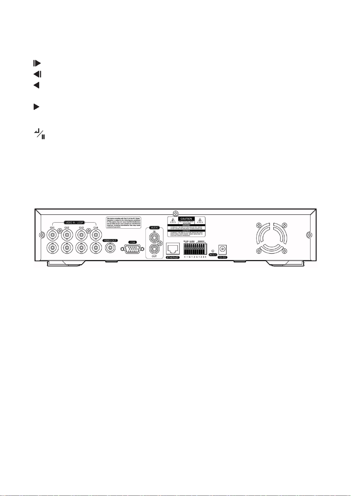
2-2. Rear Panel
The rear panel of the DVR comprises the following:
Video Input port: Four connectors for video input (NTSC/PAL).
Video Loop Through: Four connector for video loop out.
Video Out: Composite video output in NTSC/PAL format.
VGA Out : Connector for VGA monitor.
Audio In / Audio Out: RCA (line level).
Network : RJ-45 connector for LAN connection
Terminal Blocks
- RS-485: For control the PTZ cameras and external control keyboard.
- Alarm Out: This terminal blocks connect external alarms to the DVR. (5V TTL OUTPUT)
- Sensor In: This terminal connects external sensors to the DVR. (5V TTL INPUT)
Reset: This reset switch will return all the settings to the original factory settings.
DC Power Jack : Apply 12V DC using the DC adaptor supplied with equipment(DC12V / 3.33A)
Page 13
13
2-3. Start the System
To turn off the system, select SHUTDOWN under main menu (MENU >
SHUTDOWN) and unplug the power cord when the shutdown message appears.
icon indicates that pre-event-recording is set – not saving data at the HDD.
Once, event is detected, icon changes to , and it starts to record videos.
Connecting the power cord will turn on DVR. The system initialization will take approximately 10 to 20
seconds. Once the system is initialized, it will display quad screen, and begin to record video automatically.
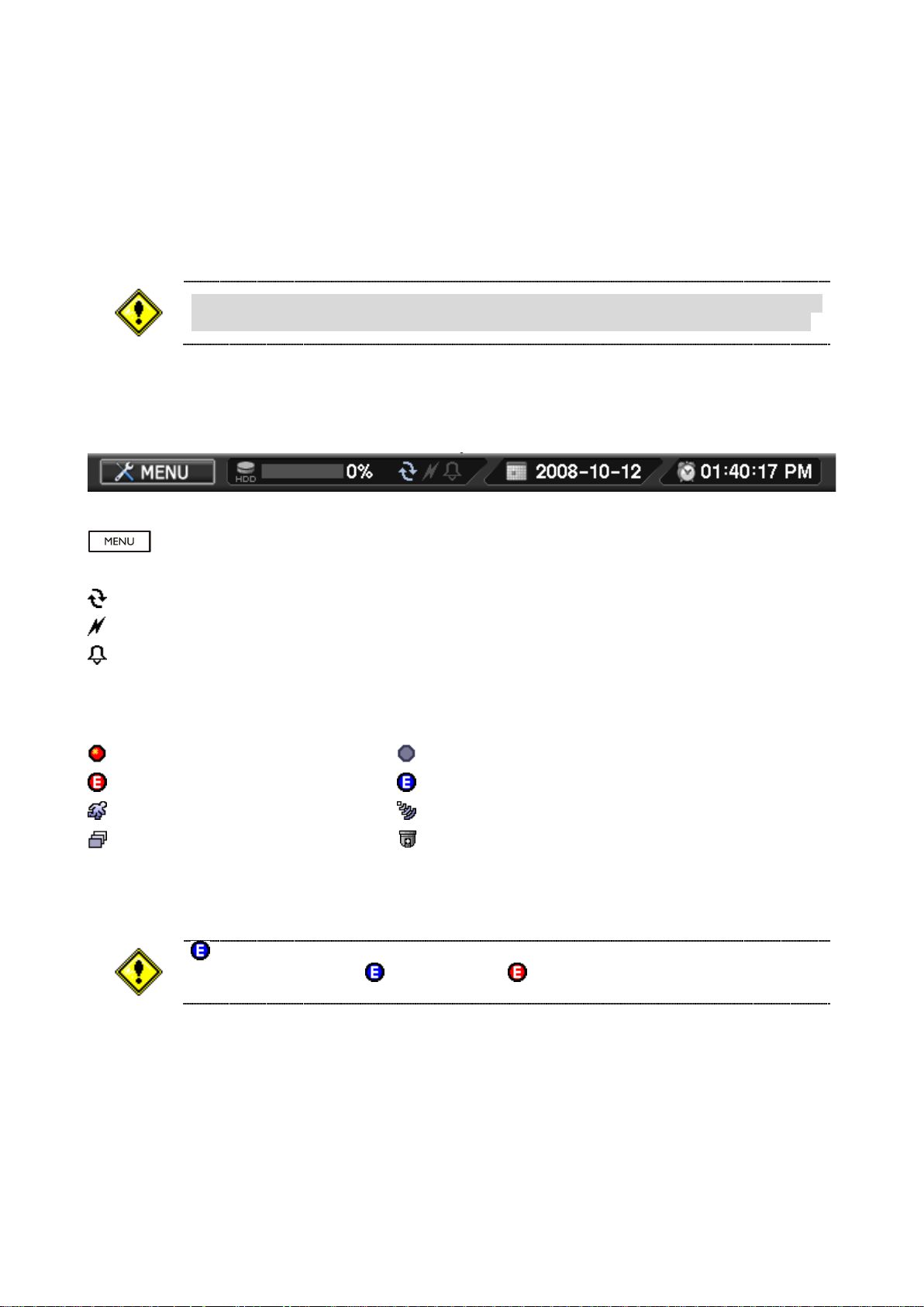
2-4. Menu Bar
The menu bar will appear on the bottom of the screen as shown below.
: Pressing the Menu will bring up the main menu list
“%”: Shows the % of HDD being used
: Turns on when the HDD is set to be overwritten.
: Turns on when the system is connected to the network
: Turns on when the Alarm is being activated
2-5. Display Icons
: Recording : No Recording
: Event Recording : Pre Event Recording
: Motion Detection : Sensor Detection
: Sequence : PTZ Camera
Page 14
14
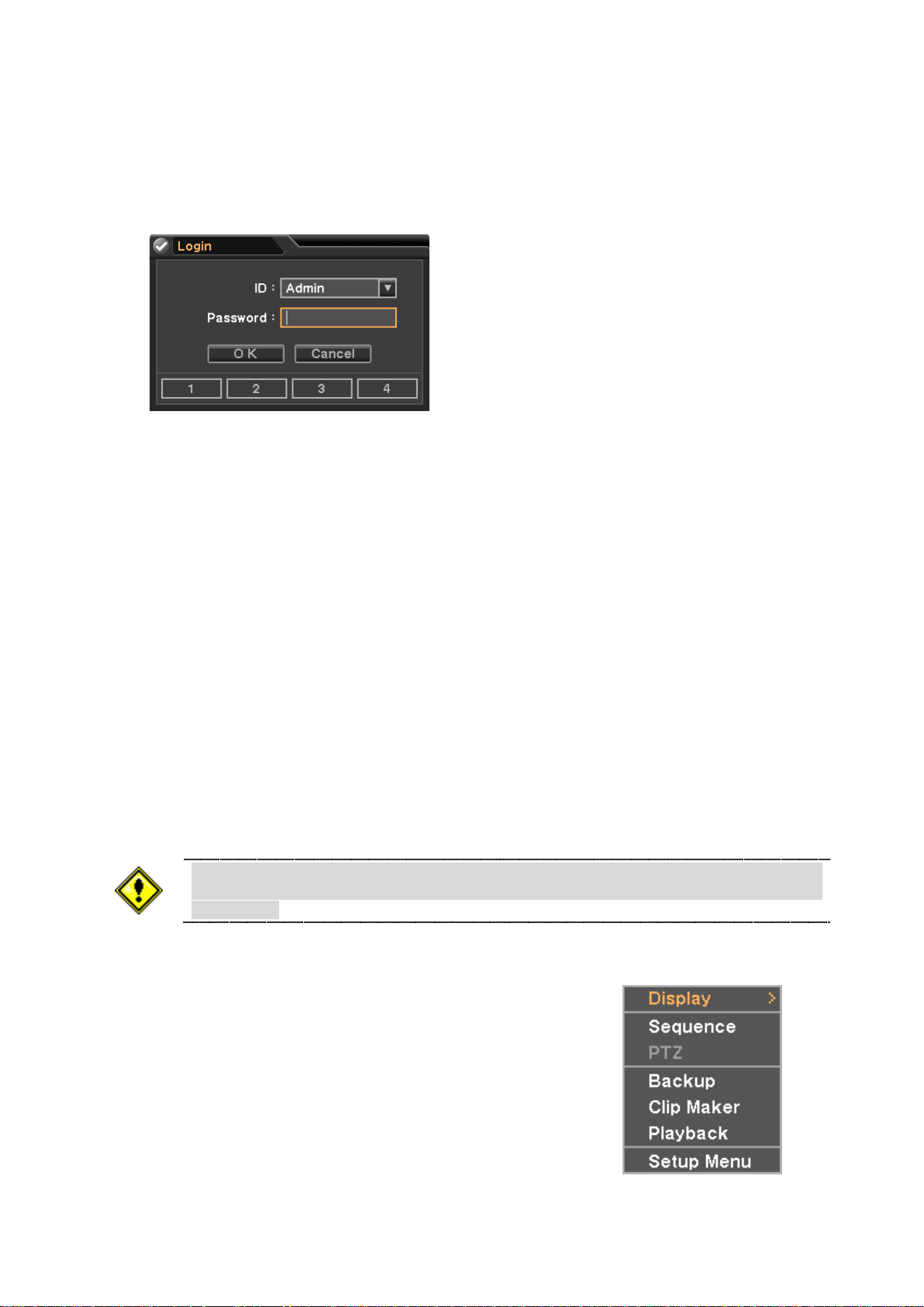
2-6. User or Admin Login
Please make sure the system log out is done when the system setting or
operation completed to prevent any unauthorized changes of system settings or
operations.
Press MENU to enter main menu screen. When Login screen appears, please enter ID (Admin or User) and
Password. Password can be set up to 8 numbers with the combination of numbers from 1 to 4. The factory
default password is „1111‟ so press OK to log in to the system. Password can be set under password set up
option (MENU > SYSTEM > Password). System will be automatically log out if it is not in-use for sometime.
This "Auto Logout Time" can be set under password set up option (MENU > SYSTEM > Password).
Admin: Admin has all authority to control DVR. (Default Password : 1111)
User: User does not have authority to access DVR menu. (Default Password : 1111)
2-7. The Main Menu
The Main Menu of DVR consists of SYSTEM, DEVICE, RECORD, DISPLAY and NETWORK. And each
menu consists of various sub menus that allow detail set up of the system. Use Mouse, Remote Controller or
Front Buttons to access to each menu.
2-8. Contextual Menu
Additional Contextual Menu screen appears by clicking right button
of the Mouse. Display option allows changing Camera on the monitor.
Select All to display all cameras on the monitor.
For other menu options on Contextual Menu please refer
to “3. DVR Configuration”.
Page 15
15
3. DVR Configuration
DO NOT remove USB Flash Memory or turn off the system during the upgrade.
Removing USB Flash Memory or Turning off the system during the upgrade may
cause system malfunctioning.
When DVR and cameras are turned on and off with one switch, DVR may cause
system errors if NTSC/PAL is set to AUTO.
Configuration import does not affect or changes system and network settings.
Network settings will also not be changed when selecting Default option.
3-1. System
Under system menu, System configuration options for general Information, Date &Time, Password, Storage,
System Log and Back Up can be selected.
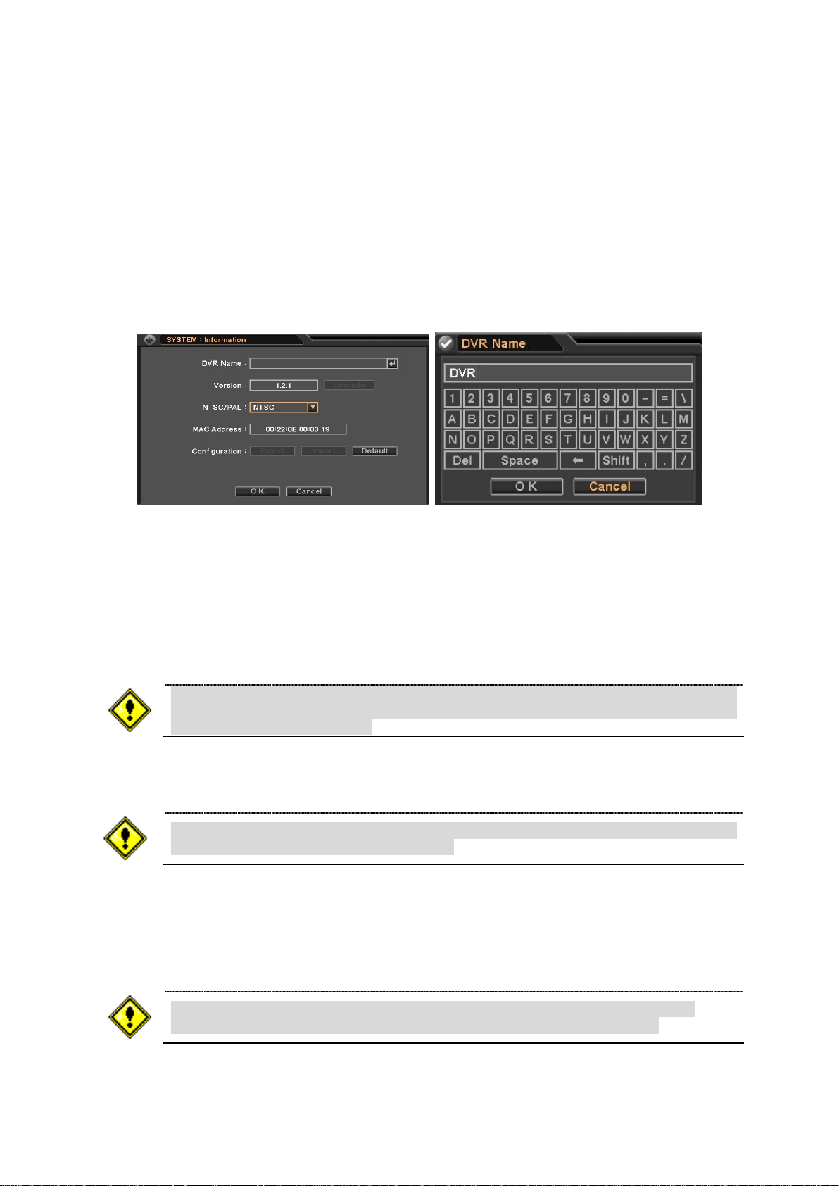
3-1-1. MENU > SYSTEM > Information
In the Information screen, DVR Name, System Version, Upgrade, Mac Address and Configuration options
can be selected.
DVR Name: Please select DVR Name and input DVR name using the virtual keyboard.
Version/Upgrade: In order to upgrade the system, save the upgrade file to USB Flash Memory and
connect it to DVR. If you press Upgrade button, upgrade process will start and it will take
approximately 5 minutes. DVR will reboot automatically when the upgrade is completed.
NTSC/PAL: Select Camera Signal System (NTSC / PAL / AUTO) which is connected to DVR.
Configuration : System settings can be saved and loaded using Configuration option
- Export: Save settings to USB Flash Memory
- Import: Load saved settings from USB Flash Memory
- Default: Load factory default settings
Page 16
16
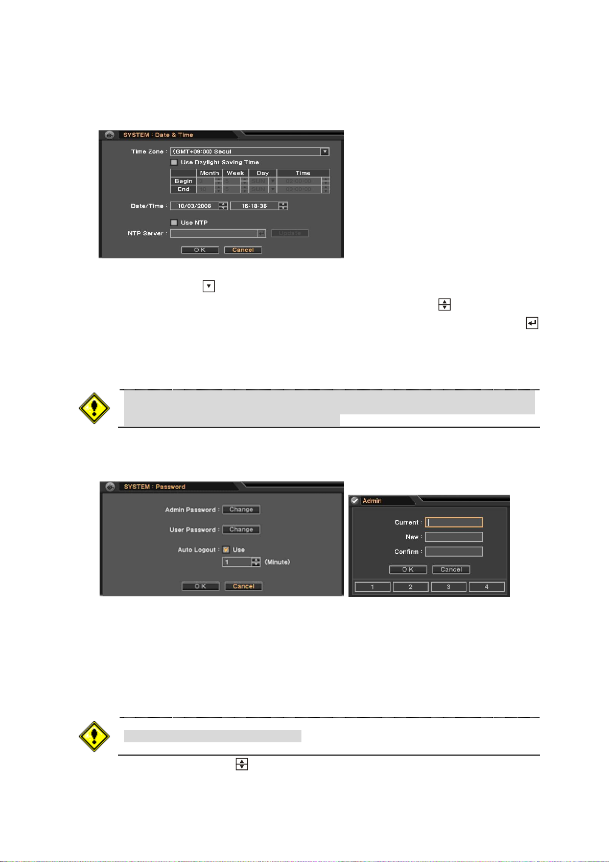
3-1-2. MENU > SYSTEM > Data & Time
NTP is not essential for DVR operation. Any type of Standard Time Server can be
used (e.g. time.windows.com). Time Synch might not be completed due to heavy
traffic or delays from the Time Synch server.
The Default password is set to „1111‟
In the Date & Time, Time Zone, Date, Time and NTP Server options can be selected.
Highlight and press Time Zone to select right Time Zone, and please check „Use Daylight Saving Time‟ if
it is applicable. Enter start and end date/time for local „Daylight Saving Time‟. Click button to set up Date
and Time. Select „Use NTP‟ to enter Time Servers to be synchronized with DVR. Highlight and press to
enter Time Server using the virtual keyboard. Press „Time Sync‟ to synchronize the DVR time with the
registered time server.
3-1-3. MENU > SYSTEM > Password
In the Password, Admin Password, User Password and Auto Logout options can be selected.
Press „Change‟ and Password set up screen will appear to set or change Admin/User Password.
Current : Enter current password
New : Enter new password
Confirm : Re-Enter new password for the confirmation
Set time interval for Auto Logout using button
Page 17
17
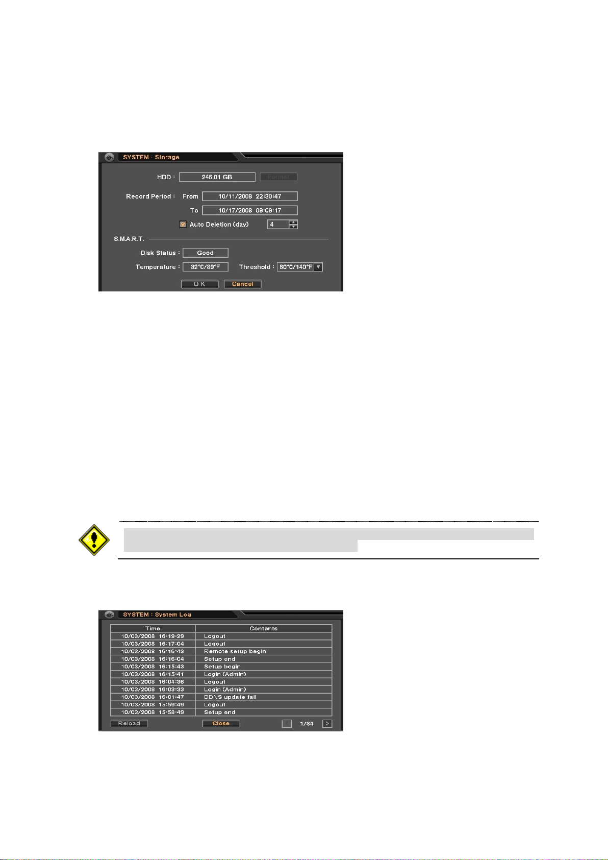
3-1-4. MENU > SYSTEM > Storage
If the HDD temperature exceeds the preset temperature under Threshold, the
system will active an alarm to notify the change.
In the Storage, HDD Format, Record Period and Smart options can be selected.
When installing the HDD for the first time, the HDD should be formatted first.
Highlight and press Format button to begin HDD format.
Record Period: displays the information on the period of recorded data.
Auto Deletion (day): Keep the recorded data for a selected day(s) from the time you set.
S.M.A.R.T option allows checking the status of installed HDD.
- Disk Status: Shows the HDD‟s condition
- Temperature: Show the HDD‟s current temperature
- Threshold : Allow to set acceptable max HDD temperature
3-1-5. MENU > SYSTEM > System Log
In the System Log, full list of system logs can be searched.
Press „Reload‟ button to refresh log list. USE < > button to search log list page by page.
Page 18
18
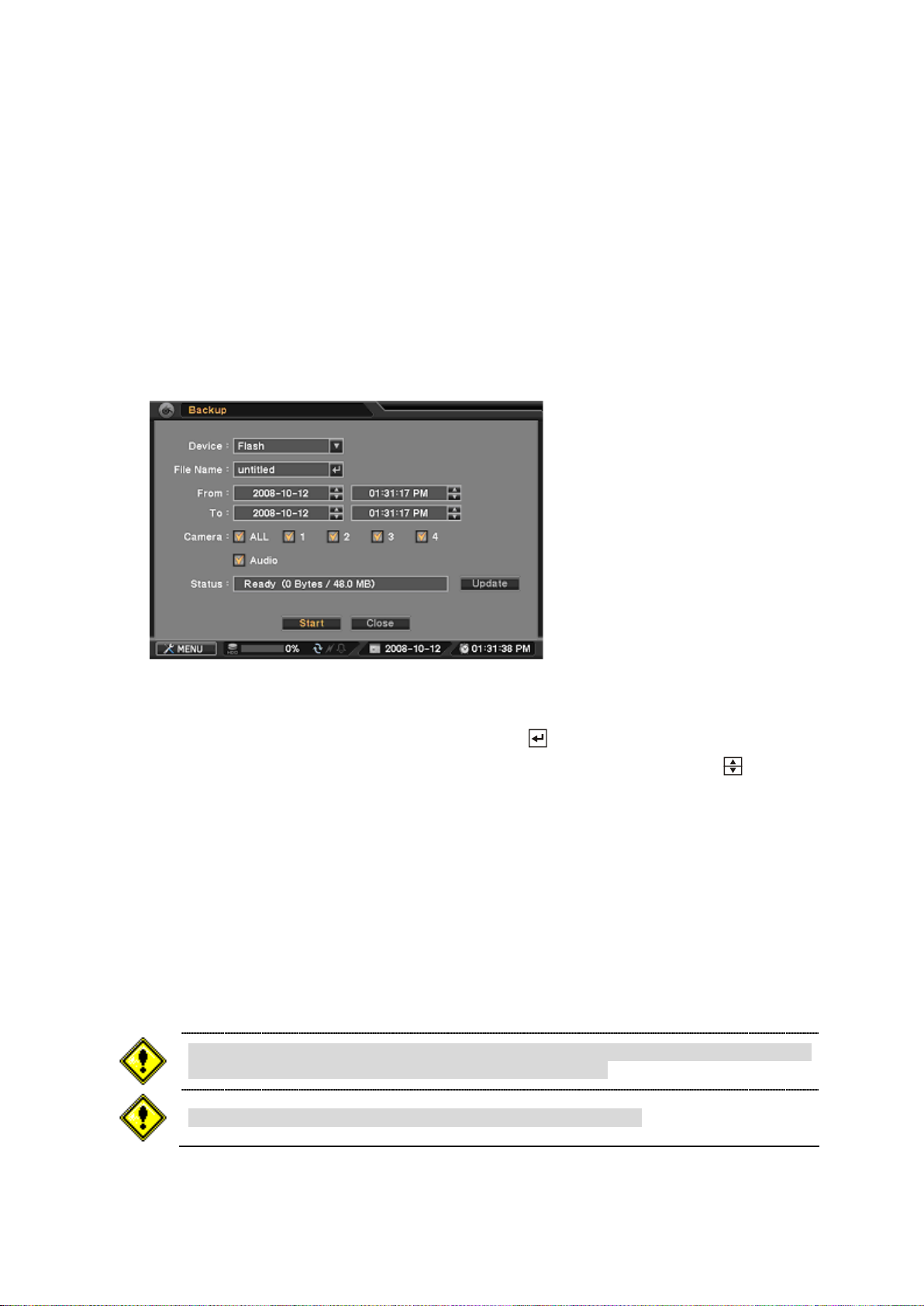
3-1-6. BACKUP
The backup process could be slowdown if the system is being monitored/playback
on the remote. The MAX capacity to back up data is 2GB.
Backup Viewer program is installed with HDxViewer program.
You can backup data that can be only played with Backup Viewer program.
Here is the direction to generate a backup file.
Please connect a flash memory drive to DVR system
Please press Backup button and select Backup, then you will see a screen like below.
(Using Mouse : Click the right button of mouse and select Backup at the menu)
If your device information does not show up at Status, please select Update button to renew your
device information.
Please input file name with virtual keyboard by clicking button.
Please select the time range of data that you want to backup at From and To using button.
Please check camera numbers that you want to backup data from.
Please check at Audio option if you have audio data with selected camera.
Please select Start button to begin backup process.
You can check backup process at Status.
It may take a long time to backup data depending on the file capacity
Now, FileName.strg file is created at your flash memory drive, so you can only play this file with Backup
Viewer Program.
Page 19

19
3-1-7. Clip Maker
The Clip Maker process could be slowdown if the system is being
monitored/playback on the remote.
You can also backup data as a clip that can be played with Quick Time Player, so you do not need Backup
Viewer program to play clip files.
Here is the direction to generate a clip file.
Please connect a flash memory drive to DVR system
Please press Backup button and select Clip Maker, then you will see a screen like below.
(Using Mouse : Click the right button of mouse and select Clip Maker at the menu)
If your device information does not show up at Status, please select Update button to renew your
device information.
Please input file name with virtual keyboard by clicking button.
Please select the time range of data that you want to backup at From and To using button.
Please check camera numbers that you want to backup data from.
Please check at Audio option if you have audio data with selected camera.
Please select Start button to begin backup process.
You can check backup process at Status.
It may take a long time to backup data depending on the file capacity
Now, FileName.m4v file is created at your flash memory drive, so you can play this file with Quick Time
Player
Page 20

20
3-2. Device
Even though it shows no video images on the monitor by setting Covert to on, it still
records the video images. It only blocks the video images from being monitored by
others.
Under Device menu, Device configuration options for Camera, PTZ, Sensor & Motion and Alarm & Buzzer
can be selected.
3-2-1. MENU > DEVICE > Camera
In the Camera, Use, Covert and Title options can be selected.
USE: Turn on or off connected cameras.
Covert: If Covert is on, no video images will be displayed on the monitor.
Title : Name each Camera using virtual keyboard by pressing
3-2-2. MENU > DEVICE > PTZ
In the PTZ, PTZ model, options such as Address, Baud Rate and Speed can be selected.
Baud Rate: Select appropriate Baud Rate from the list. Press to drop down the list.
Model: Select appropriate PTZ model from the list. Press button to drop down the PTZ list.
Address: Set PTZ address (0-255) using button.
Speed: Select PTZ speed from 1 to 10 using button.
Page 21

21
PTZ control – Basic
Please refer to PTZ camera manual for appropriate setting values for PTZ settings.
PTZ can only be controlled in single screen mode.
PTZ control extra functions are only available for PTZ camera that has specific protocols.
Select a channel connected with PTZ camera. Select PTZ from the contextual menu appears by clicking right
mouse button. In order to control PTZ with DVR control buttons, please select a channel connected with PTZ
camera and select button.
: Zoom Out : Zoom In
: Focus on near distance : Focus on far distance
: Save Presets : Load Presets
PTZ control – Extra
Select the menu button or click right button of the mouse at PTZ control screen in order to use PTZ control –
extra functions.
Auto Pan : On/Off Auto Panning
Tour : On/Off Touring
Pattern : On/Off pattern
Menu : On/Off or Set the menu of PTZ camera
Move to Origin : Bring PTZ to original position
Exit PTZ : Exit PTZ mode
Page 22

22
3-2-3. MENU > DEVICE > Sensor & Motion
In the Sensor & Motion, Sensor Type and Motion Detection options can be selected.
Sensor Type: Select Sensor Type using button. NC(Normally Closed), NO(Normally Opened)
The system provides Motion Detection function. Set Motion Detection using below option:
Use: Turn Motion Detection On or Off
Sensitivity: Set system‟s sensitivity of motion
View: Display selected Motion Area on the monitor
Area: Define the area where motion to be detected
Highlight and press „Setup‟ under area to set the area motion to be detected. Motion setup screen will
appear. The blocks indicate the area is defined for motion detection. Use mouse or enter/Channel (1~4)
buttons to select/unselect the blocks. Motion contextual menu will appear by clicking right mouse button.
Select Block: Select four blocks at a time
Clear Block: Unselect four blocks at a time
Select All: Select all blocks
Clear All: Unselect all blocks
3-2-4. MENU > DEVICE > Alarm & Buzzer
In the Alarm & Buzzer, Alarm Duration, Alarm Outs and Buzzer options can be selected.
DVR has two alarm outs which can be associated with all or selected event types.
Page 23

23
Set Alarm Duration time from 10 to 300 seconds using button.
Only camera channel #1 is recordable under D1 resolution.
Only camera channel #1 and# 2 are recordable under Half D1 resolution.
Audio will be recorded but it will not be synched with specific channels.
To record data all the times, even during Playback, DO NOT recommend selecting
Real-time Recording option. Max recording speed will be 60(50) ips but the system
will record during playback by unselecting Real-time Recording option.
Real-time Recording
None Real-time Recording
Max. Rec/Playback
120(100)ips
60(50)ips
Rec. during Playback
1 ips
60(50)ips
Select event type to be synch with Alarm out. The system has internal Buzzer can be synch with events.
Select event type to activate internal buzzer whenever the system detects events.
3-3. Record
Under Record menu, Record configuration options for Recording, Schedule, and Event can be selected.
3-3-1. MENU > RECORD > Record Setting
In the Record Setting, HDD Overwrite, Audio Record, Real-time Recording, Resolution, and Recording
Speed (ips) and Quality for Time/Event Recording options can be selected.
HDD Overwrite: Overwrite recorded data and continue recording when HDD is full.
Audio Record: Select Audio Record option to record audio with video images.
Real-time Recording: Selecting Real-time Recording will allow performing full recording/playback
speed of 120ips (100ips); however, the system will record 1ips during Playback.
Page 24

24
Resolution: Select recording resolution from CIF to D1.
Event settings will be applied only when there is an event otherwise the system is
recording by following the Time.
Set desired recording speed using button. Maximum recording speed can be changed depend on the
recording mode.
Quality: Select record image Quality from Low to Very High. Higher image quality means larger the
image size.
- Low: 1~2Kbytes / image (CIF, 30ips) - Standard: 2~3Kbytes / image (CIF, 30ips)
- High: 3~5Kbytes / image (CIF, 30ips) - Very High: 5~7Kbytes / image (CIF, 30ips)
3-3-2. MENU > RECORD > Schedule
In the Schedule, Day, From ~ To, Mode, Camera and Setting for detail recording options can be selected.
Day: Various days can be selected for recording by Day, Week (MON to FRI), Weekend (SAT to
SUN), Holiday (HOL) and All.
From ~ To: Set desired recording time using button. Time can be selected from 00:00 to 24:00.
Mode: Select recording mode by Time, Event, Time/Event (T/E) and No Record.
- Time: Continuous Record Mode
- Event: Record only when there is an event as preset
- Time & Event: Combination of Time and Event record mode.
Camera: Select cameras to be recorded.
Settings: Select desired settings of recording speed and image quality.
Page 25

25
If select Use Default Settings, the system will record at 15ips and Standard quality.
The system always follow recording settings under Recording Setting menu unless
specific time and recording options are set under Recording Schedule.
There are some Holidays falls on different days. Therefore, they have to be updated
every year.
Holiday: Press Holiday to set specific dates for Holiday setup. Set specific date by pressing Add
button. Change and delete dates using and X buttons.
3-3-3. MENU > RECORD > Event
In the Event, various event options of Pre-Event, Event REC Duration and Camera associations can be
selected.
Pre-Event (sec): Video Images occurred right before an Event can be recorded by setting Pre-
Event under Event Mode. Duration Pre-Event recording can be set using Pre-Event (sec) up to 30
seconds.
Event REC Duration (sec): Set recording duration for events up to 30 minutes.
All the events can be associated any cameras. Mark event types to be associated with each camera.
Page 26

26
3-4. Display
Color adjustment setup is only available at DVR - not for Web Client and HDxViewer,
and modified setting is also applied to recording videos.
Under Display menu, Display configuration options for OSD and Monitor can be selected.
3-4-1. MENU > DISPLAY > OSD
In the OSD, Data & Time display format, Language, Status Bar Hide can be selected.
Date Display Format: Select preferred Date Display Format from the list using button.
Time Display Format: Select preferred Time Display Format from the list using button.
Language: Select preferred Language from the list using button.
Status Bar: If you mark Auto Hide, the status bar disappears in 10 seconds while the system is not
in use.
3-4-2. MENU > DISPLAY > Monitor
In the Monitor, Sequence Duration (sec) and color control options can be selected.
Sequence Duration (sec): Set interval time for the camera sequence.
Setup: Press Setup button to adjust video color. Click or drag control box to adjust each color levels.
Page 27

27
3-5. Network
Default TCP port is 10101 but it can be set from 8000 to 12000 if it is necessary
After you modify port numbers, DVR will be automatically restarted.
Router or similar devices users need to open additional TCP ports for network
connection, such as Live, Playback, Setup, and Web.
ISP‟s(Internet Service Provider) DNS address should be inputted for using DDNS.
Under Network menu, Network configuration options for network Address and DDNS can be selected.
3-5-1. MENU > NETWORK > Address
In the Address, Information such as Type, IP address, Subnet Mask, Gateway Port and DNS can be set for
network connections.
Type: Select network type of Static or DHCP.
IP Address: Enter IP address using button.
Subnet Mask: Enter Subnet Mask using button.
Gateway: Enter Gateway using button.
Port: Select appropriate port number for external access to the system
- Remote Port (Default 10101): This port is required to be connected to DVR via HDxViewer.
- Web Port (Default 80): This port is required to be connected to DVR via Internet Explorer.
DNS: Enter DNS address using button. If user set DNS properly, user can connect to DVR
using hostname instead of DVR IP address when user set to use DDNS. .
Page 28

28
3-5-2. MENU > NETWORK > DDNS
For more specific information about DDNS and its registration and management at
autoipset.com, please see the appendix.
Dynamic DNS (DDNS) allows you to create a hostname that points to your dynamic IP or static IP address.
We also provide an update mechanism which makes the hostname work with your dynamic IP address of
DVR
In the DDNS, network options for DDNS can be selected.
Use DDNS : To decide whether using DDNS service or not
Hostname: Create a hostname that points to your dynamic IP or static IP address.
Use ID: To decide whether managing hostname through autoipset.com or not.
ID/Password: autoipset.com‟s ID and Password.
Update: Register or update the hostname at autoipset.com
Page 29

29
4. Playback
The system provides various playback menus to search recorded data.
Please click right mouse button on mouse or press playback button
on the front panel.
4-1. Display
Select display mode or camera from Display list or double click on a camera to bring up specific camera in
full screen mode. Highlight and press Hide Status Bar to keep the status bar disappear from the screen. If
you do not want to hear recorded audio, select Mute Audio.
4-2. Search Options
Please select most convenient search options from the contextual menu.
4-2-1. Go to Time
Select Go to Time to search recorded data by time/date. Set time/date using button. Go to Beginning and
End options are selectable to search the very first and last data recorded. Once desired settings are
completed, press OK to begin search, and press button to play.
Go to Beginning: Move to the very first recorded data.
Go to End: Move to the latest recorded data.
Page 30

30
4-2-2. Calendar Search
Calendar Search provides easy graphical search by displaying numbers (dates). Dates with recorded data
will be highlighted. Once you select the date, it will display record time table below.
The numbers on the top of the table shows the time frame in 24hours format, and titles on the left indicate
cameras numbers. The color bar shows the full information of recorded data on the selected date. Move the
indicator (line) to select specific recorded time of the selected date.
Once desired settings are completed, press OK to begin search, and press button to play.
4-2-3. Event Search
Event Search provides easy search by event list recorded. Select the date and type of event to find specific
data.
Page 31

31
All : System displays every events
Motion : System displays every events related to Motion
Sensor : System displays every events related to Sensor
Once find specific list of event, move up and down button to highlight the log and press button to
playback the data, and press button to play.
4-2-4. Playback Control
: Reverse Playback
: Go to the previous image
: Freeze or Stop current image
: Go to the next image
: Play the data at normal speed
To control the backward and forward playback speed, press on ◀ or ▶ repeatedly. Playback speed can
increase up to x32.
Page 32

32
5. Web Viewer
User can access to use DVR‟s Setup, Live Web Monitoring, Playback functions through Internet Explorer.
5-1. Login
User can access to the DVR‟s Remote Monitoring System if user inputs DVR‟s IP address or its registered
hostname at Internet Explorer‟s address bar.
Ex) Web port is 80(Default value) – http://hostname.autoipset.com or 211.104.176.143
Ex) Web port is not the default value – http://hostname.autoipset.com:Web port or
211.104.176.143:Web port Ex) http://hostname.autoipset.com:8080 or 211.104.176.143:8080
Port numbers can be checked at DVR MENU > Network > Address > Port
At the DVR‟s login page, User should input correct ID, Password, and Port Number in order to use Live or
Playback function.
ID : DVR‟s Administrator ID or User ID (Default ID: admin or user)
Password : DVR‟s Password for administrator or user (Default Password : “1111”)
Port Number : DVR‟s Port Number (Default Value : 10101)
*If you need more information about Port Number, please check the following manual section.
“3-5-1. MENU > Network > Address > Port “
Live : Live Web Monitoring
Playback : Search and Play the DVR‟s recorded data
5-2. Live
Users can access the Live Web Monitoring and DVR‟s configuration
Page 33

33
: One Channel View Mode.
: Change the display channel at One Channel View Mode.
: Quad View Mode.
: Full screen View Mode.
Setup: Changed the DVR configuration.(Only for administrator)
5-3. Playback
User can search and play the DVR‟s recorded data.
Playback Icon
: Backward High-Speed Play(X2, 4, 8, 16, 32) : Backward Play
: Forward High-Speed Play(X2, 4, 8, 16, 32) : Forward Play
: Jump to the beginning of data at the selected date : Backward Play by one frame
: Jump to the end of data at the selected date : Forward Play by one frame
: Pause
Page 34

34
5-3-1. Calendar Search
Web viewer may not display videos properly if user use low performance video
cards, especially on-board type.
User can select a specific time to search for the recorded data at the calendar.
As you see the picture, date marked as red color if there is recorded data
on the calendar. In addition, selected date marked as yellow color.
, : Change month / year
: Search data by inputting specific time.
: Refresh the DVR‟s recorded data information.
5-3-2. EVENT Search
User can search recorded events data through the Event Search function.
Event Search window will be come up if user clicks the Event Search button, then user should select the date
and click ok button. Now, you can select any event that you want to check on the Event list.
, : Change the Event List pages
: Event Search again with different date
Page 35

35
6. HDxViewer
HDxViewer can manage a number of DVR (maximum 16) as integrated through network.
HDxViewer can indicate video of DVR systems connected to network in 64 video channel screen at
maximum and utilize various functions such as setup, PTZ control, preset setup, search (remote/local), EMap.
① indicates current date, time, day of system where HDxViewer is installed.
② is used for search, screen capture, setup, E-Map
③ indicates list of servers registered on HDxViewer
④ is used for program shut down, server connection and disconnection, management, and PTZ control
⑤ is used for control of screen division
⑥ indicates logs detected in server and HDxViewer
⑦ is used for single channel player, network recording and adding, editing and switching of preset.
⑧ is minimizing button.
6-1. Quick Start
6-1-1. Live
User can do the Live Monitoring with HDxViewer.
1. Please install HDxViewer program on your computer, and then run the program by double clicking
HDxViewer icon on the desktop.
Page 36

36
2. Please select Server List menu like below.
3. Please select Add button and input user’s DVR server information at Server Management window.
Page 37

37
4. Please select Add button to save user’s DVR server information.
Please select the newly added Server on the list, then select Connect button.
Server Name: Please input server name that you want to use
Server Address: Please input DVR IP address or DDNS hostname
(You can check DVR IP address or DDNS host name at DVR menu-address or DDNS.)
Access Port: Please input DVR access port number. (Default port number: 10101)
User ID: Please input user ID that is the same as DVR login ID – Default : admin.
User Password: Please input DVR login password - Default : 1111.
5. Please select a camera number on server list like below to view live monitoring.
Page 38

38
6-1-2. Search
User can search and play the recorded videos with HDxViewer.
1. Please select search button after accessing to DVR.
2. Please select a DVR server to search at Select remote, then press OK button.
3. Please select the specific time, such as date, hour, and minute, to search like below.
Page 39

39
4. Please click Play button to view recorded videos.
5. Please select Live button to go back to live monitoring mode.
6-1-3. Setup
User can set DVR configuration remotely with HDxViewer.
1. Please select setup button after accessing to DVR.
Page 40

40
2. Please select a DVR server to setup at Select remote, then press OK button.
3. User can set DVR configuration with the same environment like DVR.
Please select X button to close setup window.
Page 41

41
6-2. Server list indication
Program shut down button.
If you click button, authentication window to close HDxViewer will run.
If you click any part on HDxViewer program including 'program shut down' with check on of
button of 'use log on/off' in system setup in HDxViewer setup, authentication window will run.
Connect button.
If you click button, it will try connection to the selected server in the server list.
Disconnect button.
If you click button, it will try disconnection to the selected server in the server list.
Server list management button.
If you click button, server management window will run.
PTZ control button.
If you click button, PTZ control window will run.
It indicates server name, IP address, camera and sensor registered in HDxViewer.
It indicates the status of servers (connection and event) and devices (cameras, sensors and alarms).
6-3. Program shutdown, volume, PTZ control, server connection & disconnection
6-4. Screen division, full screen and switching
You can enlarge a certain channel in full screen by double-click on that.
Page 42

42
6-5. LCD window and log
It indicates the storing, network, and HDD from the left.
It indicates the current status of network.
View event the button. If you click button, event log viewer will run.
Single channel player button
If you click button after selecting channel, a window to see single channel will run.
Network recording button
If you click button, it changes „activate status‟ icon and stores the video in the
system where HDxViewer is installed.
If you click 'go to preset' button after selecting preset, it is applied to the current
HDxViewer.
Go to preset button
If you click button, the current screen changes into preset screen.
Preset switching button
If you click button, it switches the preset consequently.
Edit preset button
If you click button, preset setup window will run.
Preset screen button
If you click button, preset addition window will run.
It in text form indicates the status of server connected with.
According to setup of server and HDxViewer, log exists or not.
6-6. Single channel player, network recording and preset
Page 43

43
6-7. Authentication
Will capture the still shot of current video and output (save or print out).
You must be authorized in authentication window to use HDxViewer.
You can run log on, log off, program shut down, program minimize, system off and system restart.
If program starts with check on in „log on/off‟ button in system setup in setup,
authentication window will run if any part of HDxViewer program including program shut down button is
clicked.
If ‟log on/off‟ button is checked, authentication window will run when „program
shut down‟ button is clicked.
① You can select commands such as log on, log off, program shut down and program minimize if you select
command in command list.
② With Select on ID list, you can select user ID. If 'show user list' is
checked off in log-on window in system setup of HDxViewer setup, you can input the ID manually with this ID
button.
③ Input password for user ID
④ If you click button, virtual keyboard will run.
⑤ If you click button, it will run the command in command list. If the ID selected through ID list were not-
existing ID or with incorrect password, command will not run.
⑥ If you click button, command will not run and authentication window will close.
6-8. Screen capture
Page 44

44
6-9. Server list
You can select menu by click of right button of mouse.
View connected DVR
If you click button, it indicates list of only connecting servers in server list.
View name / View address / View IP
If you click each button, the list can be in name, address and IP address.
The above is an example selected as name indication.
Connection / Disconnection
If you click each button, it will connect and disconnect to server.
According to the connecting status of server, it changes into:
Connection -> CCoonnnneeccttiioonn
Disconnection -> DDiissccoonnnneeccttiioonn
Menu is enabled or disabled
All connection / All disconnection
If you click each button, it will try to connect and disconnect to all servers registered in server list.
Start view camera / End view Camera
If you click each button, you can watch or not camera.
According to watching status, it changes into:
Page 45

45
Start view camera -> SSttaarrtt vviieeww ccaammeerraa
End view Camera -> EEnndd vviieeww CCaammeerraa
Menu is enabled or disabled.
Start recording / End recording
If you click each button, you can record video or not.
According to recording status, it changes into:
Start recording -> SSttaarrtt rreeccoorrddiinngg
End recording -> EEnndd rreeccoorrddiinngg
Menu is enabled or disabled.
Alarm on / Alarm off
If you click each button, you can activate alarm or dissolve.
According to alarm activating status, it changes into
Alarm on -> AAllaarrmm oonn
Alarm off -> AAllaarrmm ooffff
Menu is enabled or disabled
DVR system information
If you click button, server info window of the selected server will runs with indication of DVR information. (The
picture below shows the connected status, and may be different in disconnection status.)
6-9-1. Server connection
1) Click twice name of „not connected server‟
2) Completing connection changes icon ( ).
Page 46

46
6-9-2. Server disconnection
1) Click the connected server 2) Click the button to disconnect
3) Connection is cancelled and icon shape changes ( ).
6-9-3. Connect all servers
1) If menu is indicated by click on right button of mouse on server list, click 'All connection‟.
2) Icon of connected server is changed.
3) If you click 'disconnect all' button in menu, it will disconnect all servers.
Page 47

47
6-9-4. Watching video
1) If you double-click camera of connected server, you can watch video.
: Video is output in channel.
: Video is not being output in channel.
: Video is being recorded in the system where HDxViewer is installed.
6-9-5. Not watching video
1) If menu is indicated by click on right button of mouse on camera with video, click 'stop watching camera'
button. (or double-click camera icon in tree control)
2) Video of camera gets hidden and icon changes. ( )
* Watching video and its dissolution can be done through drag and drop.
6-10. Server list use
If you click button of server list, server list management window will run.
There are server name, IP address (of server), connecting method and server status information in server list
management window.
You can add server in the list or delete and bring server list from other system with HDxViewer.
Page 48

48
6-11. Single channel player
If you click 'single channel player button, single channel player window will run.
It offers saving full motion, still shot capture, PTZ control, live screen and full screen
6-12. Preset
If you click 'add preset' button, you can save the current screen status. (If clicked, add preset window will run
and add preset.)
If you click 'edit preset' button, preset setup window will run and can edit/add/delete.
If you click 'switching' button, presets are consequently switching and display videos.
6-13. Setup
If you click the setup button ( ), setup selection window will run.
You can select HDxViewer setup or server setup by click on 'setup selection' button (local or remote).
If you click 'remote selection' button, the currently connected server is selected.
You can start setup by click 'OK' or stop setup by 'cancel'.
Page 49

49
6-13-1. Local setup
If you click „setup‟ button, setup selection window will run.
HDxViewer setup window will run if server is not connected at all.
If you click 'OK' after clicking on 'local selection', HDxViewer setup window will run. Only system administrator
can do setup.
6-13-2. Remote setup
If you click the 'setup' button, setup window will run.
Without any server connected, HDxViewer setup window will run.
If you click 'OK‟ button after firstly clicking 'remote selection' and secondly
selecting server to setup by clicking 'server selection', remote setup window will run.
It is possible to set DVR configuration, such as system, device, record, display, and network in remote setup.
Only system administrator (admin) can run setup.
6-14. Search
If you click 'search' button, remote search will run.
You can select search in HDxViewer system or search in server by clicking 'remote search
selection'.
If you click „remote selection' button, you can select the currently connected server.
If you click „OK' button, search window will run.
If you click 'Cancel' button, you can stop searching.
Page 50

50
6-15. Backup Viewer
Using this button user can load backup data. If user succeeds to load a file, recorded date
for backup data will be marked at calendar like below.
This color indicates the date the backup data exists.
This color indicates the user selecting date.
If user selects the colored date on calendar, recorded camera numbers will
be marked like below.
The button to save image.
If you click button, current playback image is captured and still image window runs.
Backup data can be played with Backup Viewer program.
Please connect memory stick that holds backup data before running Backup Viewer Program.
.If user selects one of camera numbers, the beginning of recorded image will be shown at the main screen,
and the recorded time range will be marked at playback selection zone like below.
User can select a specific time to search at playback selection zone.
Page 51

51
6-16. Local Viewer
Using this button user can load backup data. If user succeeds to load a file,
recorded date for backup data will be marked at calendar like below.
This color indicates the date the backup data exists.
This color indicates the user selecting date.
If user selects the colored date on calendar, recorded camera numbers will
be marked like below.
Network recorded data from HDxViewer can be played with Local Viewer program.
Please select the network recorded server name after running Local Viewer Program.
.If user selects one of camera numbers, the beginning of recorded image will be shown at the main screen,
and the recorded time range will be marked at playback selection zone like below.
User can select a specific time to search at playback selection zone.
Page 52

52
The button to save image.
If you click button, current playback image is captured and still image window runs.
The button to save in AVI
It can save current video as a motion video file.
Usage: 1. Play video where user want to save from as AVI and click save AVI button.
2. User should play video until it reach the end of video where user want to save as
AVI.
3. Even though user increases play speed, AVI file is saved normally.
4. If user click stop button, saving to AVI process will be done.
The button to add print.
If you click button, add a current screen to the print list and run printing window..
The button to view print.
If you click button, printing window runs.
Enlarge or reduce images partly.
Page 53

53
APPENDIX
A-1. DDNS(Dynamic Domain Name Server)
Dynamic DNS (DDNS) allows you to create a hostname that points to your dynamic IP or static IP
address (IP Camera, DVR, and Web Server). We also provide an update mechanism which makes the
hostname work with your dynamic IP address of DVR. You can use DDNS service after signing up for
autoipset.com or without signing up process.
A-1-1. Use DDNS service after signing up for autoipset.com
1. Sign up for autoipset.com
Please run Internet Explorer program, and then please type http://www.autoipset.com at Internet
Explorer‟s address bar. You will see the web page for DDNS service like below.
Please click “Registration” in order to sign up for autoipset.com.
Page 54

54
Please fill up the blank with correct information, and then click submit button. You should check the
duplication of your user ID by clicking “Check ID” before submission.
2. Log in
Please log in with your ID and Password.
After you log in, you can see the list of your registered DVR like below at the product list.
Page 55

55
3. DDNS registration
Status
Specification
Elapsed time since last update is Less than 5 minutes
Elapsed time since last update is more than 5 minutes and less than 20 minutes
Elapsed time since last update is more than 20 minutes
No update history
Please select DDNS menu at your DVR with the following route.
DVR > MENU > NETWORK > DDNS
First, please input a hostname that you want to use, and then please select the check box for Use ID.
Next, please input ID and Password that you registered at autoipset.com, and then please click “Update”
button. Finally, if you see the message, “DDNS: Succeeded in updating”, then all the registration process is
done.
4. DDNS Management
5. Delete the registered DDNS
Please select the DVR DDNS that you want to delete, and then click “Delete” button.
Page 56

56
A-1-2.Use DDNS without signing up for autoipset.com
Please select DDNS menu at your DVR with the following route.
DVR > MENU > NETWORK > DDNS
Please input a hostname that you want to use, and then please click “Update” button. If you see the message,
“DDNS: Succeeded in updating”, then all the registration process is done.
Page 57

57
A-2. Compatible HDD models
3.5" HDD List
NO
PRODUCT
MANUFACTURE
MODEL
CAPACITY
REMARKS
1
HDF1212
SEAGATE
ST380815AS
80GB
OK
2
HDF1212
SEAGATE
ST3160815AS
160GB
OK
3
HDF1212
SEAGATE
ST3160310CS
160GB
OK
4
HDF1212
SEAGATE
ST3250310CS
250GB
OK
5
HDF1212
SEAGATE
ST3250310NS
250GB
OK
6
HDF1212
SEAGATE
ST3250318AS
250GB
OK
7
HDF1212
SEAGATE
ST3250312CS
250GB
OK
8
HDF1212
SEAGATE
ST3500320AS
500GB
OK
9
HDF1212
SEAGATE
ST3500410AS
500GB
OK
10
HDF1212
SEAGATE
ST3500321CS
500GB
OK
11
HDF1212
SEAGATE
ST3500418AS
500GB
OK
12
HDF1212
SEAGATE
ST31000340SV
1TB
OK
13
HDF1212
SEAGATE
ST31000322CS
1TB
OK
14
HDF1212
HITACHI
HDS721680PLA380
80GB
OK
15
HDF1212
HITACHI
HDT721016SLA380
160GB
OK
16
HDF1212
HITACHI
HDS721616PLA380
160GB
OK
17
HDF1212
HITACHI
HDP725025GLA380
250GB
OK
18
HDF1212
HITACHI
HDT721025SLA380
250GB
OK
19
HDF1212
HITACHI
HDP725050GLA360
500GB
OK
20
HDF1212
HITACHI
HDS721010KLA330
1TB
OK
21
HDF1212
HITACHI
HDT721010SLA360
1TB
OK
Page 58

58
A-3. Specifications
[Video]
Input
Composite
4CH, 1.0Vp-p, 75Ω, NTSC / PAL
Output
Main Monitor
Composite 1CH BNC, 1.0Vp-p, 75Ω, NTSC / PAL
1 CH VGA
Loopback Output
4CH BNC 1.0Vp-p, 75Ω
[Audio]
Input & Output
1CH Line input / 1CH Line output
Aduio Codec
ADPCM
[Recording]
Compression Format
H.264 Baseline Profile (MPEG4 Part10)
Compression Rate
4 Step Selectable
Frame Rate
Realtime mode
CIF : MAX. 120 / 100 fps
D1 : Channel 1 select only
(NTSC/PAL)
Triplex mode
CIF : MAX. 60 / 50 fps
Half D1 : Channel 1, 2 select only
Recording Mode
Time Continuous / Schedule / Motion / Sensor
Motion Detection
Each Channel Area selectable
[Display]
Display Rate
Real time display per camera
Multiscreen Display
1 / 4 / Auto Sequence
[Playback]
Playback Mode
Normal Playback, Various playback speed (forward and backward)
Search Mode
Archived data Search, Date/time, Calendar, Event
[Storage]
Internal HDD
Interface Type
1 SATA Internal HDD
Max HDD Capacity
Support 1000GB
File System
Own File System
[Network]
Remote Access Tool
ActiveX Base Web, HDxViewer Access
Dynamic IP support
With DDNS Server
Network Interface
10/100 bas-T Ethernet(RJ-45)
[Others]
Sensor Input
4CH (TTL, terminal block NO/NC Programmable)
Alarm Output
2CH (TTL, terminal block)
PTZ Camera Control
1 RS-485
Control Applications
Via Front Consol Control, USB Mouse, Remote Controller, TCP/IP
Backup
Clip copy to USB, Quick Time (M4V)
Power
12V DC
Dimensions(WxHxD)mm
351x276x71
 Loading...