

Page 1

BDx-Series
Installation Manual (Ver 2.06)
Page 2

BDx-Series Installation
This product is made by advanced technology and passed reliability and compatibility test.
Product quality can be guaranteed.
This is an installation guide for BDx-Series user.
This guide gives you BDx-Series’s external specification, name, PAN/TILT control, the way of
attaching peripheral devices and configuration of system program.
If you are first user of BDx-Series DVR, even though you are experienced with similar products
like this, we recommend you to read this manual carefully and follow the instructions inside
before using this product.
CAUTION
The copyright of this manual belongs to Manufacturer.
It is prohibited to copy this manual without permission.
We do not guarantee, if your system is damaged by your mis-using disapproval components
or mis-operation.
If you have any problems or questions with our product, please contact the dealer you
bought from or Manufacturer.
If you need to open the system for modification or repairing, it is recommended that you have
to request an engineer’s assistance by contacting the dealer you bought it from or
Manufacturer.
BDx-Series is a registered trademark of Manufacturer DVR system.
This product has certification for domestic and industrial use. Also, it has taken CE for
Europe, FCC for the U.S.
2
Page 3

BDx-Series Installation
Warning
This is a Class A product. In a domestic environment this product may cause radio
interference in which case the user may be required to take adequate measures.
This equipment has been tested and found to comply with the limits for a Class A digital
device, pursuant to Part 15 of the FCC Rules. These limits are designed to provide
reasonable protection against harmful interference when the equipment is operated in a
commercial environment. This equipment generates, uses and can radiate radio frequency
energy and, if not installed and used in accordance with the instruction manual, may cause
harmful interference to radio communications. Operation of this equipment in a residential
area is likely to cause harmful interference in which case the user will be required to correct
the interference at his own expense.
3
Page 4

BDx-Series Installation
1. Windows Setup....................................................................................................................6
1.1 System Requirements.................................................................................................6
1.2 Monitor Resolution.......................................................................................................6
1.3 Power Options & Display Properties............................................................................7
2. Hardware Installation............................................................................................................8
2.1 Hardware Configuration...............................................................................................8
2.1.1 Specifications....................................................................................................8
2.1.2 Check the contents............................................................................................8
Table of Contents
2.1.3 Layout..............................................................................................................11
2.1.4 Connecting the boards.....................................................................................16
2.2 Connecting Hardware................................................................................................18
2.2.1 Connecting Network........................................................................................18
2.2.2 Connecting camera PTZ..................................................................................18
2.2.3 Connecting Sensor Input.................................................................................20
2.2.4 Connecting Digital Output................................................................................20
2.2.5 Connecting Watch Dog....................................................................................21
2.2.6 Selection of audio input....................................................................................22
2.3 Installing Device Driver..............................................................................................24
2.3.1 BDF0303m / BDF0303 / BDS0606 / BDS1212 Driver.......................................24
2.3.2 BDE2424 / BDS2424 / Overlay Driver..............................................................30
3. Installing the Software........................................................................................................34
3.1 Installing the software................................................................................................34
3.2 Reinstalling the software............................................................................................36
3.2.1 Saving the Settings..........................................................................................36
3.2.2 Uninstalling the Software.................................................................................37
3.2.3 Reinstalling the Software.................................................................................37
3.2.4 Modifying Settings...........................................................................................38
3.3 Installing the Client Software......................................................................................39
3.3.1 Install Client Software......................................................................................39
3.3.2 Addition of DVR Server....................................................................................39
4. DDNS (Dynamic Domain Name Server).............................................................................40
4
Page 5

BDx-Series Installation
4.1 DDNS settings on your DVR......................................................................................40
4.1.1 Creating a Host Name.....................................................................................41
4.1.2 Advanced Hostname management..................................................................41
4.2 Access to DVR by Domain Name..............................................................................42
5. Network Configuration........................................................................................................44
5.1 DVR network setup....................................................................................................44
5.2 Connecting from Remote place..................................................................................45
5.2.1 Use of the network client software....................................................................45
5.2.2 Use of the Web Client......................................................................................47
5.3 Router Setup.............................................................................................................48
Appendix A. Advanced Host Name Management....................................................................49
1. Creating an ID and password on our free DDNS Service.............................................49
2. Host Name Registration...............................................................................................51
3. Host Name Management.............................................................................................53
4. DDNS settings on your DVR........................................................................................54
5
Page 6
BDx-Series Installation
1. Windows Setup
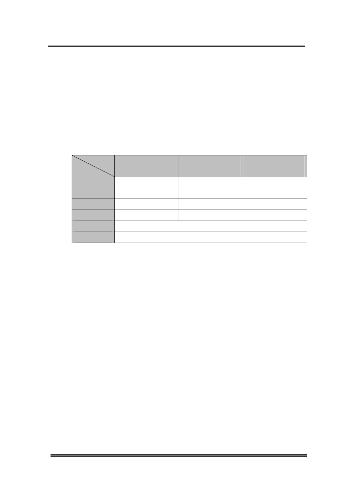
1.1 System Requirements
• Supported OS
Windows 2000, Windows XP
• System Requirements
Model
SPEC
CPU Cel 1.0 or higher Cel 2.0 or higher Pentium4 2.4G or
RAM 128MB or higher 256MB or higher 256MB or higher
Main Board Intel chipset board Intel chipset board Intel chipset board
Graphic ATI Radeon (video memory 32MB or higher)
DirectX DirectX 7.0a or higher
(We recommend you to update driver to the latest version because a old driver may
not properly run.)
BDF0303
BDS0606
BDS1212
BDS4812
BDE2424 / BDS2424
BDS4824
higher
1.2 Monitor Resolution
Select “Display Properties”.
All programs have been designed to be run at the screen resolution of 1024×768 or
higher.
If the monitor does not support this resolution or has not been configured, the program
may not properly run.
Select “Medium(16 bit)” or “Highest (32 bit)” in the Color quality field, and “1024 by 768” in
the Screen resolution area as shown below:
6
Page 7
BDx-Series Installation
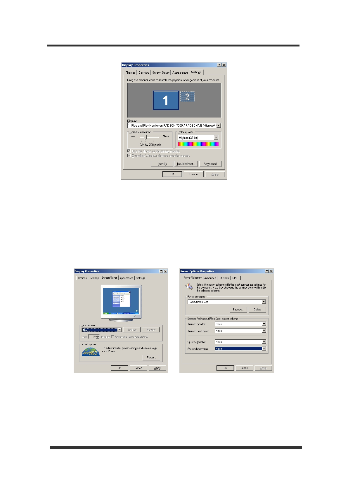
1.3 Power Options & Display Properties
Select “None” in the Screen saver field, and click “Power…” in the “Monitor power” area.
When the Power Options Properties window appears, select “Never” in the “Turn off
monitor” and the “Turnoff hard disks” fields.
If above settings are not made, program errors may occur.
7
Page 8

BDx-Series Installation
2. Hardware Installation
2.1 Hardware Configuration
2.1.1 Specifications
Video Inputs 4 4 4,8,16 4,8,16
Display speed
NTSC/PAL(fps)
Recording speed
NTSC/PAL(fps)
DI / O 8 / 4 4 / 4 8 / 4 16 / 8 8 / 4 16 / 8 8 / 4 16 / 8 16 / 8
RS422 / 485
H/W watch-dog
Audio(Audio BD
or sound device)
*It defends on computer sound device.(2 Line in or 1 Microphone in normal) (fps : frame per second)
BDF03
03m
6/
6
6/
6
1Line in
BDF03
03
30/
25
30/
25
BDS06
06
60/
50
60/
50
BDS12
12
120/
100
120/
100
BDE24
24
8 16 16 16 16
240/
200
240/
200
BDS24
24
240/
200
240/
200
BDS48
06
480/
400
60/
50
BDS48
12
480/
400
120/
100
√ √ √ √ √ √ √ √
√ √ √ √ √ √ √ √
*Sound
4Line in 8Line in
Device
*Sound
Device
*Sound
4Line in 8Line in
Device
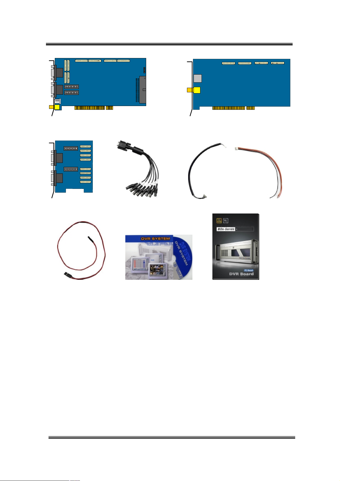
2.1.2 Check the contents
After removing package, make sure that the following contents.
BDS48
24
480/
400
240/
200
*Sound
Device
Please contact the dealer if any items are missing.
BDx-Series contents
( )- quantity
Video capture B/D
Overlay B/D
Video Input B/D
External Video cable
Internal Video cable
PTZ control cable
Watch-Dog cable
Software CD
Installation manual
BDF03
03m
BDF03
03
BDS06
06
BDS12
12
BDE24
24
BDS24
24
BDS48
06
BDS48
12
√ √ √ √ √ √ √ √ √
√ √ √
√ √ √
√(2) √(2) √ √(2) √(2) √(2) √(2)
√(2) √(4) √(4) √(4) √(8)
√ √ √ √ √ √ √ √
√ √ √ √ √ √ √ √
√ √ √ √ √ √ √ √ √
√ √ √ √ √ √ √ √
8
BDS48
24
Page 9
BDx-Series Installation
ON
1 2 3 4 5 6 7 8
ON
1 2 3 4 5 6 7 8
<Video Capture B/D> <Overlay B/D(Real time display)>
ON
1 2 3 4 5 6 7
8
ON
1 2 3 4 5 6 7
8
<Video Input board> <External Video cable> <Internal Video cable> <PTZ control cable>
<Watch-Dog cable> <Software CD> <Installation manual>
9
Page 10
BDx-Series Installation
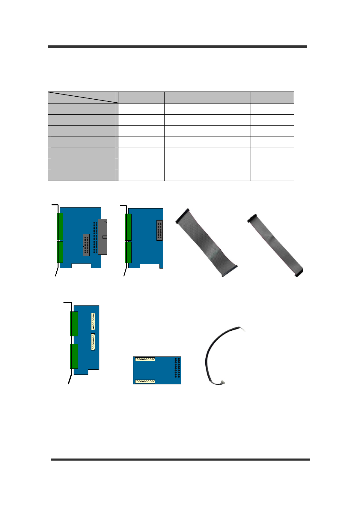
DVR Accessory contents
( )- quantity
DIO0804 DIO1608 AUDIO 4IN AUDIO 8IN
1st DIO Board
2nd DIO Board
40pin DIO cable
20pin DIO cable
Audio Input Board
Audio A/D Board
Internal audio cable
<1st DIO Board> <2nd DIO Board> <40pin DIO cable> <20pin DIO cable>
√ √
√
√ √
√
√ √
√ √
√ √(2)
<Audio Input Board> <Audio A/D Board> <Internal Audio cable>
10
Page 11
BDx-Series Installation
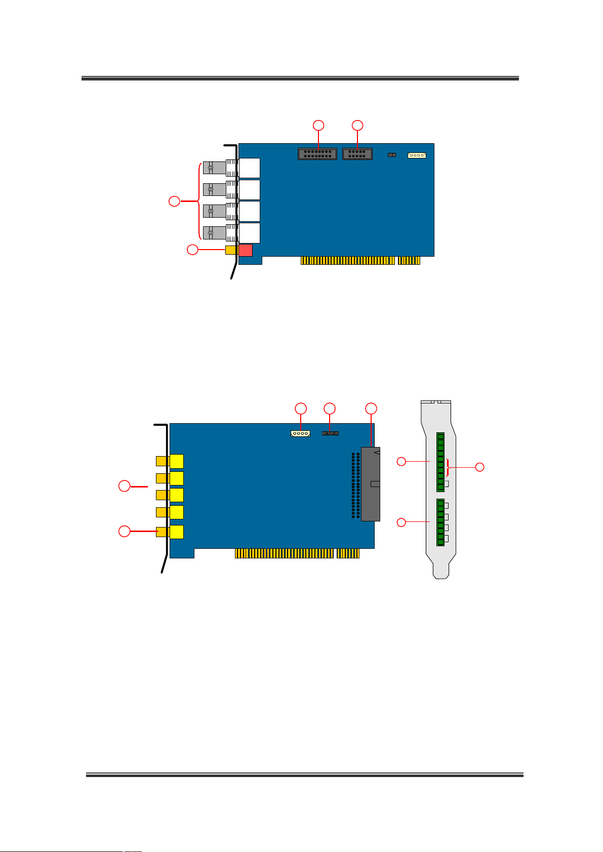
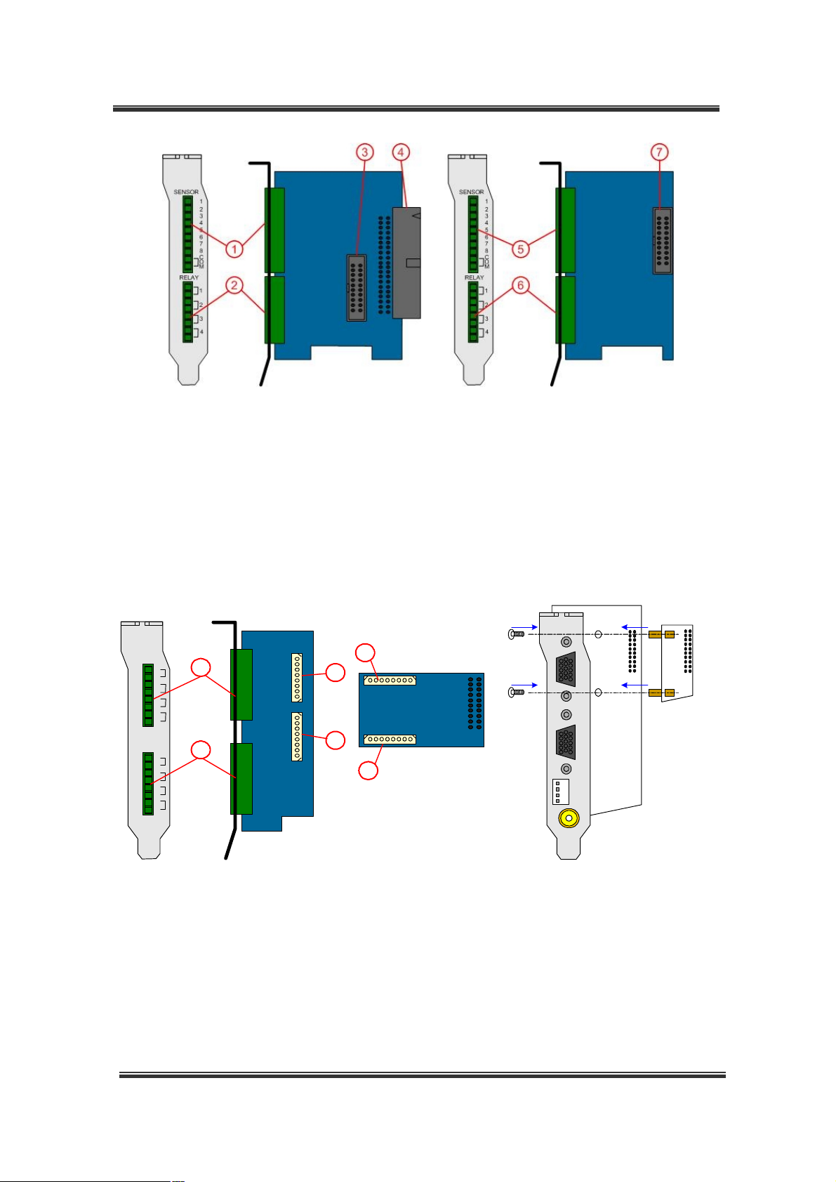
2.1.3 Layout
① Video Inputs : Camera In 1~ 4
② Audio Input : 1Ch audio line level in
3
1
2
4
<Capture B/D - BDF0303m>
③ DI Connector : DI(1~8) control port. Connecting to the DIO board (1~8)
④ DO Connector : DO(1~4) control port. Connecting to the DIO board (1~4).
3 4 5
SENSOR
1
2
3
4
RELAY
5
6
7
7
8
C
O
M
1
2
3
4
6
1
8
2
<Capture B/D - BDF0303> <DIO Board>
① Video Inputs : Camera In 1~ 4
② Thru pass Output : 1Ch Live display
③ RS422/RS485 port : Camera PTZ control
④ Watch-Dog Connector : Hardware Reset
⑤ DIO Connector : DIO control port. connecting to the DIO board
⑥ DI Connector : Sensor Input (1~4)
⑦ RS422/RS485 port : Camera PTZ control
⑧ DO Connector : Dry contact Output (1~4). Alarm control
11
Page 12
BDx-Series Installation
3 45 6
1
2
ON
1 2 3 4 5 6 7 8
ON
13
14
1 2 3 4 5 6 7 8
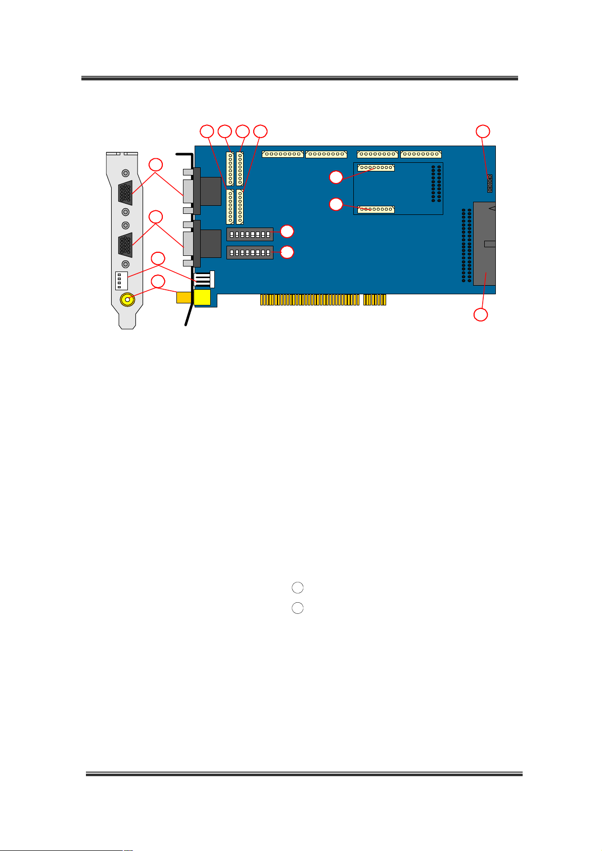
< Capture B/D – BDS0606 / BDS1212>
① Video Inputs (external connector):
15
17
18
11
12
16
⑪ Video termination switch: Camera In 1 ~ 8
Camera In 1 ~ 8
② Video Inputs (external connector):
Camera In 9 ~ 16
⑫ Video termination switch: Camera In 9 ~ 16
Termination resistor(75ohm)
Termination resistor(75ohm)
③ Video Inputs (internal connector): 1 ~ 4 ⑬ RS422/RS485 port : Camera PTZ control
④ Video Inputs (internal connector): 5 ~ 8 ⑭ Thru pass Output : 1Ch Live display
⑤ Video Inputs (internal connector): 9 ~ 12 ⑮ Watch-Dog Connector : Hardware Reset
⑥ Video Inputs (internal connector): 13 ~ 16 ⑯ DIO Connector : DIO control port. connecting to
the DIO board
17
Audio Inputs (optional) : Line level 1 ~ 4
18
Audio Inputs (optional) : Line level 5 ~ 8
12
Page 13
BDx-Series Installation
5
6
1 2
7 8
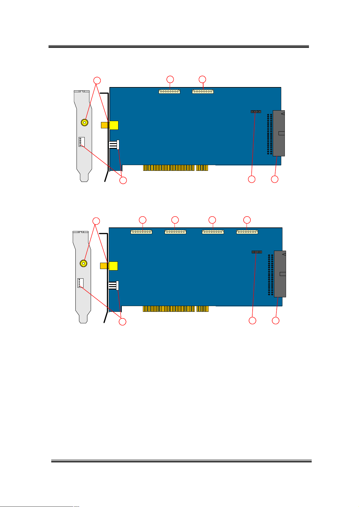
< Capture B/D – BDE2424>
5
1 2 3 4
6
7 8
< Capture B/D – BDS2424>
① Video Inputs (internal connector): 1 ~ 4
② Video Inputs (internal connector): 5 ~ 8
③ Video Inputs (internal connector): 9 ~ 12
④ Video Inputs (internal connector): 13 ~ 16
⑤ Thru pass Output : 1Ch Live display
⑥ RS422/RS485 port : Camera PTZ control
⑦ Watch-Dog Connector : Hardware Reset
⑧ DIO Connector : DIO control port. connecting to the DIO board
13
Page 14
BDx-Series Installation
14 3 2
6
5
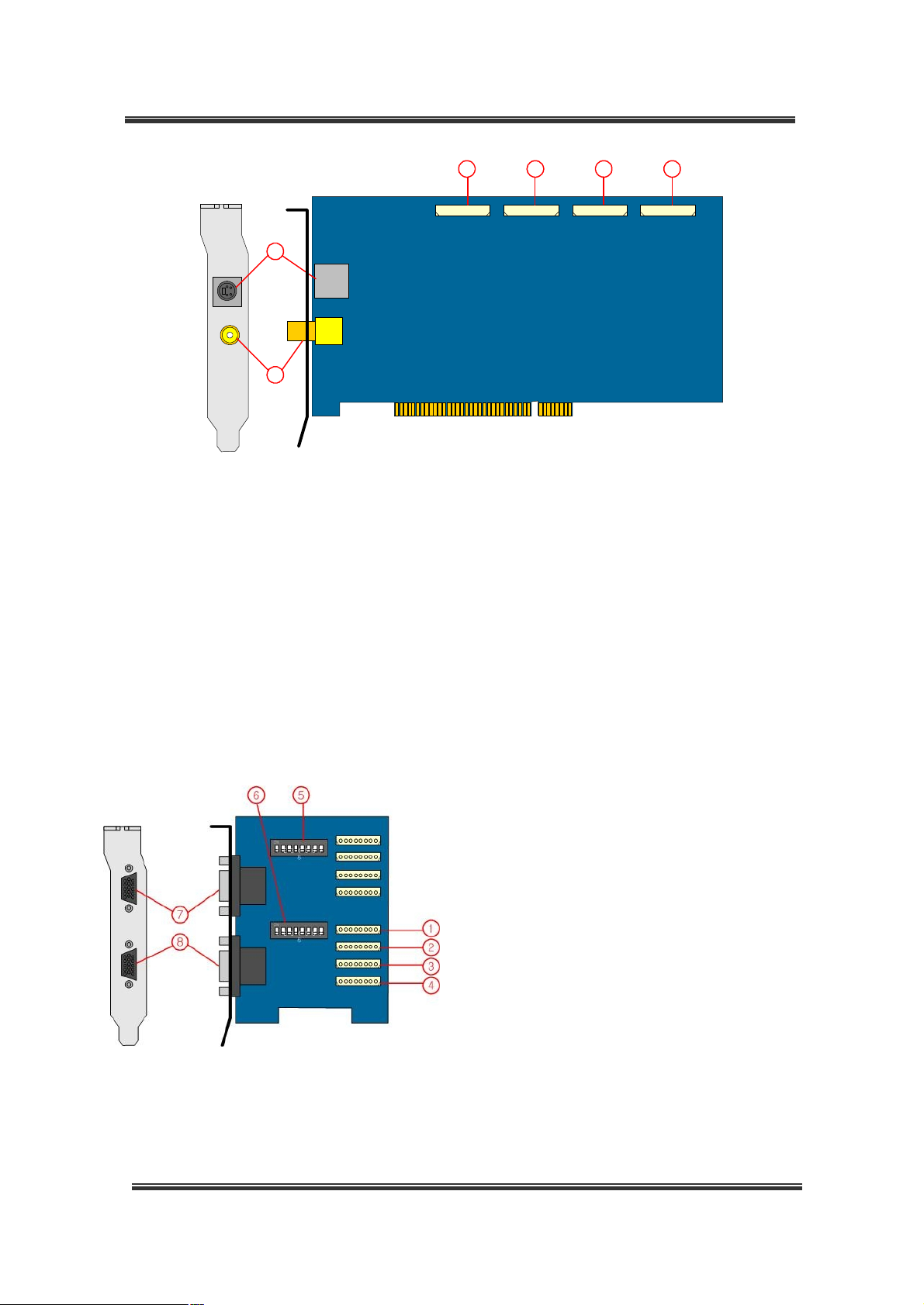
< Overlay B/D(Real time display) - OVL480>
Real time display board is component of BDS48xx.
① Video Inputs (internal connector): 1 ~ 4
② Video Inputs (internal connector): 5 ~ 8
③ Video Inputs (internal connector): 9 ~ 12
④ Video Inputs (internal connector): 13 ~ 16
⑤ Video Output : Multiple video output
⑥ S-Video Output : Multiple video output
① Video Inputs (internal connector): 1 ~ 4
② Video Inputs (internal connector): 5 ~ 8
③ Video Inputs (internal connector): 9 ~ 12
④ Video Inputs (internal connector): 13 ~ 16
⑤ Video termination switch: Camera In 1 ~ 8
⑥ Video termination switch: Camera In 9 ~16
Termination resistor(75ohm)
Termination resistor(75ohm)
⑦ Video Inputs(external connector): 1 ~ 8
⑧ Video Inputs(external connector): 9 ~ 16
<Video Input Board>
14
Page 15
BDx-Series Installation
<1st DIO Board> <2nd DIO Board>
① Sensor Input connector : Input 1 ~ 8 and common
② Alarm Output : Output 1 ~ 4. Dry contact output
③ DIO Connector : connecting to the 2nd DIO board
④ DIO Connector : DIO control port. connecting to the capture board
⑤ Sensor Input connector : Input 9 ~ 16 and common
⑥ Alarm Output : Output 5 ~ 8. Dry contact output
⑦ DIO Connector : connecting to the 1st DIO board
AUDIO
1
1
G
2
G
3
G
4
G
2
5
G
6
G
7
G
8
G
5
3
4
6
<AUDIO Input Board> <AUDIO A/D Board> <Connecting to Capture B/D>
① Audio Input Connector : Line level Input 1 ~ 4
② Audio Input Connector : Line level Input 5 ~ 8
③ Audio Input Connector(Internal) : connecting to the Audio A/D board, Audio 1~4
④ Audio Input Connector(Internal) : connecting to the Audio A/D board, Audio 5~8
⑤ Audio Input Connector(Internal) : connecting to the Audio Input board, Audio 1~4
⑥ Audio Input Connector(Internal) : connecting to the Audio Input board, Audio 5~8
15
Page 16
BDx-Series Installation
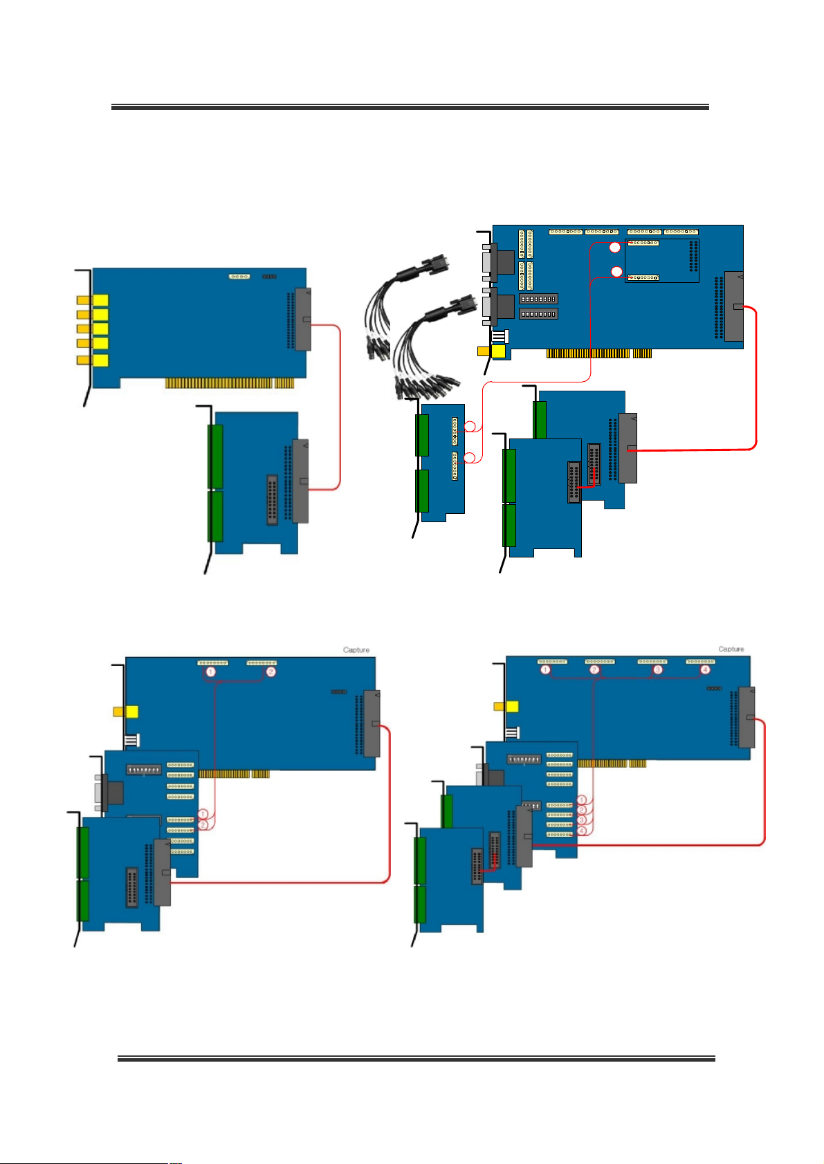
2.1.4 Connecting the boards
Video In
cables
Capture
1
2
ON
1 2 3 4 5 6 7 8
ON
1 2 3 4 5 6 7 8
1
2
Audio
Guide
DIO
Guide
<BDF0303> <BDS0606 / BDS1212>
<BDE2424> <BDS2424>
16
Page 17
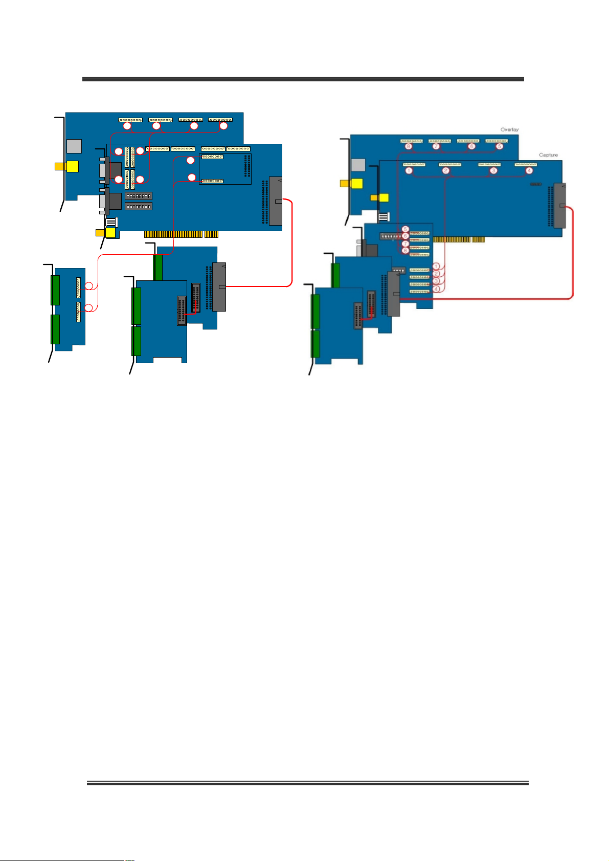
BDx-Series Installation
Overlay
4 3 2 1
Capture
2
1
4
3
ON
1 2 3 4 5 6 7 8
ON
1 2 3 4 5 6 7 8
5
6
5
6
<BDS4812 / BDS4806> <BDS4824>
17
Page 18

BDx-Series Installation
2.2 Connecting Hardware
2.2.1 Connecting Network
LAN/xDSL Port
Internet
Client PC
2.2.2 Connecting camera PTZ
4 3 2 1
<Connecting PTZ from DIO board (only for BDF0303)> <Connecting PTZ from BDF0303 board>
<RS422 / 485>
1. Rx + or TRx +
2. Rx - or TRx -
3. Tx +
4. Tx -
RS422 / 485 cable
1. Orange: RX+ / TRX+
2. Red : RX- / TRX-
3. Brown : TX+
4. Black : TX-
18
Page 19

BDx-Series Installation
ON
1 2 3 4 5 6 7 8
ON
1 2 3 4 5 6 7 8
1. Black : RX+ / TRX+
2. Brown : RX- / TRX-
3. Red : TX+
4. Orange : TX-
<Connecting PTZ from BDS0606 / BDS1212>
1. Black : RX+ / TRX+
2. Brown : RX- / TRX-
3. Red : TX+
4. Orange : TX-
<Connecting PTZ from BDE2424 / BDS2424>
RS422 / 485 cable
RS422 / 485 cable
<RS422 / 485>
1. Rx + or TRx +
2. Rx - or TRx -
3. Tx +
4. Tx -
<RS422 / 485>
1. Rx + or TRx +
2. Rx - or TRx -
3. Tx +
4. Tx -
Camera PTZ RS-422 Capture Board
TX+ RX+
TX- RX-
RX+ TX+
RX- TX-
Camera PTZ RS-485 Capture Board
TRX+ TRX+
TRX- TRX-
19
Page 20

BDx-Series Installation
2.2.3 Connecting Sensor Input
<DIO Board>
Connect one signal line of sensor (infrared rays sensor, heat perception sensor, magnetic
sensor) to the desired sensor number and then connect another line to the ‘COMMON’ port.
(You can set the type-NC or NO- of sensor at “Setup” mode -> “DIO”).
Use another Adapter for the all sort of sensor’s power supply.
2.2.4 Connecting Digital Output
<DIO Board>
Use this at 12V or less operating voltage and 300mA or less operating current.
When controlling lamp and AC operated equipment, control it using separate outside relay.
During normal operation the control output contact is maintained at “Open” status, and during
control output the output contact is changed to “Close(short)” status.
20
Page 21

BDx-Series Installation
2.2.5 Connecting Watch Dog
Watch-Dog
cable
Connect from
the computer
reset button
Connect to
the computer
reset pin
<Connecting watch-dog and computer reset pin for BDF0303>
ON
1 2 3 4 5 6 7 8
ON
1 2 3 4 5 6 7 8
Connect from the
computer reset button
Connect to the
computer reset pin
<Connecting watch-dog and computer reset pin for BDS1212(BDS0606)>
Connect from the
computer reset button
<Connecting watch-dog and computer reset pin for BDS2424(BDE2424)>
Connect to the computer reset pin using the watch dog cable.
21
Connect to the
computer reset pin
Page 22

BDx-Series Installation
2.2.6 Selection of audio input
a) Soundcard user
<Choose between ‘line-In’ and ‘Microphone’ for the audio source>
▪ Microphone user (1CH audio)
We recommend you to choose a microphone that have amplifier. Because few sound cards
have audio amplifier with a built-in their own board.
Run the DVR software and go to Setup -> Audio Tab . Select ‘Use Sound card Device’.
<Select Microphone> <Select a camera number>
In this case, camera1 image is recorded together with the audio inputted to channel1 of
sound devices.
▪ Line-In user (2CH audio)
Left channel of stereo line-in is Audio1 and Right channel is Audio2.
Run the DVR software and go to Setup -> Audio Tab . Select ‘Use Sound card Device’.
<Select Line-In> <Select a camera number>
In this case, camera1 image is recorded together with the audio inputted to channel1 of
sound devices. camera2 image is recorded together with the audio inputted to channel2 of
sound devices.
22
Page 23

BDx-Series Installation
▪ Configuration the settings for Sound Device
In case of using the sound card, the voice communication can be improved if setting of audio
equipment for the Windows’s system is as below.
[Sounds Tab] Scheme : No sound
[Volume Tab] Speaker settings / Advanced / Performance
. Hardware acceleration : Full, . Sample rate conversion quality : Good
[Audio Tab] Playback volume - Microphone and Line : Mute. Volume up to max
Recording volume - Select input Microphone or Line in.
- Microphone volume Advanced – check Boost check box
b) Audio Board User
Audio Board should be installed in order to use multi-channel audio.
(Audio Board is compatible with BDS0606, BDS1212, BDS4806 and BDS4812.)
Line In 1
GND
Line In 4
GND
Line In 5
GND
Line In 8
GND
AUDIO
G
G
G
G
G
1
2
3
4
G
5
6
G
7
8
G
<AUDIO INPUT Board>
Run the DVR software and go to Setup -> Audio Tab . Select ‘Multi Channel Device’.
In this case, camera1 image is recorded together with the audio inputted to channel1 of audio
board. Camera2 – Audio CH2 …. Camera8 is recorded with Audio CH8.
23
Page 24

BDx-Series Installation
2.3 Installing Device Driver
Install the board in the PC, and boot the PC. Then, the PC will automatically detect the board
(by PNP) and will be ready to install the driver. The user can easily install the driver file saved
in the installation diskette or HDD by designating the folder classified according to the OS type.
After the driver file is installed, the IRQ of the installed card must not conflict or be
shared with another card or equipment. However, if the IRQ of the installed card is
shared by another card or equipment, insert the card into a different PCI slot or manually
specify the IRQ through CMOS setup of the main board.
Operating systems supporting the driver include Windows98SE, Windows 2000, and
windows XP.
Manufacturer guarantees the compatibility only with ATI-series video cards, not other
video cards.
Install the driver as described below:
2.3.1 BDF0303m / BDF0303 / BDS0606 / BDS1212 Driver
2.3.1.1 Windows XP/2000
Turn off the PC, and insert the board in the PCI slot. Turn on the PC, and run the system.
Windows XP/2000 will automatically detect the new hardware device and recognize it as a
multimedia video controller.
Select “Install from a list or specific location (Advanced)”, and click "Next>".
24
Page 25

BDx-Series Installation
Insert the provided CD or a floppy diskette containing the driver, and click “Next>” to search for
the driver.
Click “Continue Anyway”.
Click “Finish”.
Windows XP / 2000 will automatically detect the new hardware devices.
Install the other “4(16)ch Video Slave Capture Device” drivers in the same way as described
above.
25
Page 26

BDx-Series Installation
In case of BDF0303m, once the drivers are successfully installed, the two new devices will be
added to Device Manager:
l “MINIDVR Video Capture Device”
l “MINIDSR Audio Capture Device”
In case of BDF0303, once the drivers are successfully installed, the two new devices will be
added to Device Manager:
l “4ch Video Capture Device”
l “4ch Slave Capture Device”
In case of BDS0606, once the drivers are successfully installed, the four new devices will be
added to Device Manager:
In case of BDS1212, once the drivers are successfully installed, the eight new devices will be
added to Device Manager:
l “16ch Slave Capture Device”
l “16ch Slave Capture Device”
l “16ch Slave Capture Device”
l “16ch Slave Capture Device”
l “16ch Video Capture Device”
l “16ch Video Capture Device”
l “16ch Video Capture Device”
l “16ch Video Capture Device”
When you installing the drivers, you may get error messages.
If errors occured, You can see mark on that drivers from Device Manager window. Reboot the
system then, they will be disappeared. They will not make any problem.
26
Page 27

BDx-Series Installation
2.3.1.2 Windows98
Turn off the PC, and install the board in the PCI slot.
Run the system by turning on the computer.
The OS will automatically start to search for PCI Multimedia Video Device.
Select “Search for the best driver for your device (Recommended)”, and click “Next>”.
27
Page 28

BDx-Series Installation
Select “Specify a location”. Insert the provided CD or a floppy diskette containing the driver.
Open the folder, and click “Next>” to search for the driver.
If the correct driver is found, the dialog will display “4(16)ch Video Capture Device”.
If you see this message, click “Next>”.
Click “Finish”.
Windows 98 will automatically detect the new hardware devices.
28
Page 29

BDx-Series Installation
Install the other “4(16)ch Video Slave Capture Device” drivers in the same way as described
above.
In case of BDF0303m, once the drivers are successfully installed, the two new devices will be
added to Device Manager:
l “MINIDVR Video Capture Device”
l “MINIDSR Audio Capture Device”
In case of BDF0303, once the drivers are successfully installed, the two new devices will be
added to Device Manager:
l “4ch Video Capture Device”
l “4ch Slave Capture Device”
In case of BDS0606, once the drivers are successfully installed, the four new devices will be
added to Device Manager:
In case of BDS1212, once the drivers are successfully installed, the eight new devices will be
added to Device Manager:
l “16ch Slave Capture Device”
l “16ch Slave Capture Device”
l “16ch Slave Capture Device”
l “16ch Slave Capture Device”
l “16ch Video Capture Device”
l “16ch Video Capture Device”
l “16ch Video Capture Device”
l “16ch Video Capture Device”
29
Page 30

BDx-Series Installation
2.3.2 BDE2424 / BDS2424 / Overlay Driver
2.3.2.1 Windows XP/2000
Windows XP/2000 will automatically detect the new hardware device and recognize it as a
multimedia video controller.
Select “Install from a list or specific location (Advanced)”, and click "Next>".
Insert the provided CD or a floppy diskette containing the driver, and click “Next>” to search for
the driver.
Click “Continue Anyway”.
30
Page 31

BDx-Series Installation
Click “Finish”.
Once the driver is successfully installed, the new device will be added to Device Manager:
l “16Ch / 240 fps Capture Board” (In case of BDS2424)
l “8Ch / 240 fps Capture Board” (In case of BDE2424)
l “Overlay Board” (In case of Overlay Board)
31
Page 32

BDx-Series Installation
2.3.2.2 Windows 98
Turn off the PC, and install the board in the PCI slot. Run the system by turning on the computer.
The OS will automatically start to search for PCI Multimedia Video Device.
Select “Search for the best driver for your device (Recommended)”, and click “Next>”.
Select “Specify a location”. Insert the provided CD or a floppy diskette containing the driver.
Open the folder, and click “Next>” to search for the driver.
32
Page 33

BDx-Series Installation
If the correct driver is found, the dialog will display “16(8)Ch / 240 fps Capture Board” or
“Overlay Board”.If you see this message, click “Next>”.
Click “Finish”.
Once the driver is successfully installed, the new device will be added to Device Manager:
l “16Ch / 240 fps Capture Board” (In case of BDS2424)
l “8Ch / 240 fps Capture Board” (In case of BDE2424)
l “Overlay Board” (In case of Overlay Board)
33
Page 34

BDx-Series Installation
3. Installing the Software
3.1 Installing the software
Open the provided CD, and locate the file in Windows Explorer.
To install the DVR program, run the “Setup.exe” file contained in the CD in Windows Explorer.
Click “Next>”.
Enable Extention Resolution : 352*240 / 720*240 / 720*480(NTSC), 352*288 / 720*288 /
720*576(PAL)
Select camera type (NTSC or PAL). Click “Next>”.
34
Page 35

BDx-Series Installation
When the setup process is completed, click “Finish”.
Once the DVR program is successfully installed, the system will be automatically rebooted, and
the following icon will be created on the Desktop:
You have to log in to use the program.
You can use the program by clicking LOG-IN Button after typing User ID and Password.
Default registered ID and Password :
Version 2.1.0.23 or higher software version : ID - admin , Password - 1111
Version 2.1.0.22 or lower software version: ID - Administrator , Password - 111
Click
35
Page 36

BDx-Series Installation
3.2 Reinstalling the software
3.2.1 Saving the Settings
Before installing a new-version of the software, the user needs to save the current settings of
the system. To install a new program while maintaining the existing settings, do the following:
If the DVR program is running, click the “LOG ON” button and exit the system by selecting “Exit
Program”. Run Windows Explorer, and go to C:\Program Files\DVRMain.
Locate and run the “BackupReg.exe” file.
Click “Open” in the Export Registry File area, and specify the location to save the settings.
Click Export to save the settings to a file with the current time as its file name.
When saving is completed, exit the software.
36
Page 37

BDx-Series Installation
3.2.2 Uninstalling the Software
To install the DVR program while the system is on, remove the existing program first. However,
if the program is running, click the “LOG ON” button and exit the system by selecting “Exit
Program”.
Select “Start" → "Settings" → "Control Panel”.
Select the “Add or Remove Programs”.
Select the DVR Program, and click Change/Remove.
Click “OK” to remove the existing program.
3.2.3 Reinstalling the Software
Refer the 3.1 Installing the software
37
Page 38

BDx-Series Installation
3.2.4 Modifying Settings
Launch Windows Explorer, and go to C:\Program Files\DVRMain.
Locate and run the “BackupReg.exe”.
Click “Open” in the Import Registry File area, and specify the location to save the settings.
Click the “Import” button to load the settings.
When importing is completed, the current setting will be replaced with the previous settings.
38
Page 39

BDx-Series Installation
3.3 Installing the Client Software
3.3.1 Install Client Software
Minimum Requirements
- Processor: Intel Pentium III 800MHz or higher
- Main Memory: 128MB or higher
- Video Card (32MB or higher): Recommended ATI series video card
- OS: Windows 98/ME/2000/XP
Run the client program, and the screen shown below will appear. Continue the process to
complete installing the program in the local computer. The default installation folder is
“C:\Program Files\DVRClient”.
If the client program has been already installed, a dialog box asking whether to remove the
existing program will be displayed. Click “OK” to remove the existing program. After the
existing program is completely removed, run the client program again.
Click “Finish” to finish the installation. Then, the following icon will be created on the Desktop.
3.3.2 Addition of DVR Server
Register DVR systems at Client software to connect the DVR system at remote place.
Refer 5.2 network configuration and connecting.
39
Page 40

BDx-Series Installation
4. DDNS (Dynamic Domain Name Server)
If you are using DYNAMIC addressing from your ISP (Internet Service Provider), you will need
to register with our DDNS service.
You do not need to register with our DDNS service if you were supplied a STATIC IP address
from your ISP. Please check with your ISP if you are unsure of how your IP address is
configured.
4.1 DDNS settings on your DVR
The DDNS settings must also be set on your DVR to use the DDNS service.
The set up process can be completed at the Network Tab which you can find at: DVR S/W ->
System Setup.
40
Page 41

BDx-Series Installation
4.1.1 Creating a Host Name
First, check box next to: “Use DDNS” to activate the related spaces. Enter the Host Name and
click the “Registration” button; You may use alpha and numerical characters as well as hyphens
for your Host Name. (i.e. [A~Z], [a~z], [0~9] or [-] for your host name and it is case sensitive).
You should see your host name as follows;
Registration will be complete once you click the “OK” and “Save” button.
4.1.2 Advanced Hostname management
You don’t have to use Hostname management, if you are normal user.
If you are using advanced Hostname management, you will need to register with our DDNS
service.
Please refer the Appendix A
41
Page 42

BDx-Series Installation
4.2 Access to DVR by Domain Name
If your DDNS service registration is successful, you can access your DVR through your web
browser or the provided CNB DVR Client S/W.
1) Access via the Client S/W
Open your Client S/W program and click the on the “link” button. A DVR Server Management
window will appear.
Enter your domain name in the “IP Address” field at the Server Connect window.
(Refer to your S/W manual for more detailed instructions.)
42
Page 43

BDx-Series Installation
2) Access by Web Browser
Enter the domain name into the Internet Explorer’s address bar.
For example, domain name : http://dvrname.ipdvrfree.com (when a web port is default value)
If a web port is 8080, type http://dvrname.ipdvrfree.com:8080
(Refer to your S/W manual for more detailed instructions.)
43
Page 44

BDx-Series Installation
5. Network Configuration
5.1 DVR network setup
Go to the DVR software -> Setup -> Network
This is an item to designate basic matters so that system may be connected to network.
▪ Public IP Subscriber
Check on ‘Support Web Viewer’. You can input other port number if default port number of
‘80’ is not workable. Contact your ISP for available ports for web server construction.
44
Page 45

BDx-Series Installation
▪ Private IP Subscriber
Private IP requires ‘Proxy Setting’ for web monitoring. Insert public IP address of IP sharer or
router that has public IP address.
You can insert domain name instead of IP address.
You have to setup Port forwarding or DMZ of each of the IP sharer or router.
BestCap DVR uses default port of 80, 7074, 7075, 7076, 7077, 49557, 49559 and
49560 for streaming. (Look up their user manual for details)
Web Server Port : You can input other port number if default port number of ‘80’ is not workable.
5.2 Connecting from Remote place
5.2.1 Use of the network client software
DVR servers should be registered on the client software due to connect.
Input a DVR information in the DVR server list window by clicking connection button.
45
Page 46

BDx-Series Installation
Click the “ADD” button after type Server name, Site code(100-001), Server IP address, User ID,
User password. And click the “SAVE” button to save the information.
Server name Input name in order to identify server.
Server
Input more detailed information on server.
description
Site code
Server
IP address
User ID
If this access code is different from the access code of the server to be
connected, access is rejected. (Default is 100-001)
This is an item where internet address of server is inputted. Input IP address
or domain name.
This is an item where user ID registered on server is inputted. If there does
not exist user ID inputted on the server for connection, access is rejected.
User password This is an item where password for the already inputted user ID is inputted.
You can change network TCP and UDP port number from “DETAIL SETUP”. But, recommended
to leave as default. (Refer to the software user manual.)
Clicking and selecting the server to be connected from list make change to status.
Click “CONNECT” button in order to connect selected servers in regular sequence.
46
Page 47

BDx-Series Installation
5.2.2 Use of the Web Client
Type IP address or domain name of DVR server into the Internet Explorer’s Address bar and
click “GO”.
([e.g.] http://211.000.000.0 or http://dvrname.ipdvrfree.com)
If you are using non default port number for the web server, then type the address as below:
([e.g.] Port 8000: http://211.0.0.0:8000 or http://dvrname.ipdvrfree.com:8000)
If this log in window does not appear, check Network Setup of your DVR and ‘Port
forwarding settings’ of IP sharer (Router). Disable firewall block to the DVR
software, DVR Mediaserver and Apatch. Change web server port if your local ISP
blocks port 80.
When the monitoring window does not appear, disable ‘Popup Stopper ’ in Tools of
Internet Explorer.
You can use the program by clicking LOG-IN Button after typing User ID, Password.
When you connect DVR for the first time, your client system download and install ActiveX. It
may take several minutes according to your network condition.
(Once Active X installed, the below Monitoring window appears directly from the next time.)
47
Page 48

BDx-Series Installation
5.3 Router Setup
If your DVR system network condition is using private IP in a Local network and you connect the
DVR out of the local network, you have to setup Port forwarding or DMZ of each of the IP sharer
or router.
DVR use port numbers as below.
Required port numbers for port forwarding
Function TCP/UDP
WEB TCP 80
Connecting TCP 7074
Audio TCP 7075
Video TCP 7076
Media TCP 7077
Audio1 UDP 49557
Audio2 UDP 49559
Alive UDP 49560
For detail configuration setup, refer the configuration manual for each router or IP sharer.
Port
48
Page 49

BDx-Series Installation
Appendix A. Advanced Host Name Management
If you are using DYNAMIC addressing from your ISP (Internet Service Provider), you will need
to register with our DDNS service.
We recommend that you first determine if you are using dynamic addressing and, if so, register
your DVR on our DDNS website.
You do not need to register with our DDNS service if you were supplied a STATIC IP address
from your ISP. Please check with your ISP if you are unsure of how your IP address is
configured.
To join our DDNS service, you will have to provide an ID and Password.
1. Creating an ID and password on our free DDNS Service
1. Access our DDNS Website by going to: http://www.IpdvrFree.com
2. Click on the “Member Join” button, on the lower right hand side of the webpage.
49
Page 50

BDx-Series Installation
3. Enter an ID (which must be more than 4 and less than 12 characters, alpha and or numerical).
Please check your ID with the “[check]” button to make sure the ID you choose is available.
Choose your Password (which also must be more than 4 and less than 12 characters, alpha
and or numerical). Confirm your (Password). Enter your Name and E-Mail address.
4. The registration will be complete once you click the “OK” button.
The DDNS Service Administer will send a confirmation e-mail to the Subscriber’s e-
mail address, so please enter your e-mail address correctly.
50
Page 51

BDx-Series Installation
2. Host Name Registration
1. Once your registration is complete, enter your User ID and Password on the main page.
Once you are logged on, you should see the following message:
“Welcome to DVR management server : guest”
2. After login, click the “Registration” button to go to the Server Registration page.
51
Page 52

BDx-Series Installation
3. At the Server Registration page, enter the “Serial Number” and “Registration No.” which is
attached to the rear of the unit.
4. Choose a “Host Name”. Remember: the ID and password you used to register with our
DDNS service is separate and not the same as your “Host Name”.
You may use alpha and numerical characters as well as hyphens for your host name. (i.e.
[A~Z], [a~z], [0~9] or [-] for your host name and it is case sensitive). Please check your host
name with the “[check]” button to make sure the host name you choose is available.
Registration will be complete once you click the “OK” button.
5. After your host name registration is complete, click the “List” button at the top of the page,
your host name should be appear on the list if your registration was successful.
52
Page 53

BDx-Series Installation
3. Host Name Management
You can register multiple host names at the DDNS Service website. You can also edit or
delete your host name here at anytime.
When you click your URL from the Domain Name LIST, you can access a specific DVR by your
web browser. The “Status” column shows the elapsed time since your last update.
Status Specification
Elapsed time since last update is Less than 5 minutes
Elapsed time since last update is more than 5 minutes and less then 20 minutes
Elapsed time since last update is more than 20 minutes
No update history
Modifying or Deleting your Domain name:
Check ① and click “[Info change]” to modify your Domain name information.
Check ① and click “[Delete]” to delete your Domain name.
When you click the URL(②), you can access your DVR by web browser. (If the DVR is turned
off or unchecked “Support Web Viewer” box which is one of DVR configuration menus, a “This
page cannot be displayed” message will appear.)
53
Page 54

BDx-Series Installation
4. DDNS settings on your DVR
The DDNS settings must also be set on your DVR to use the DDNS service.
The set up process can be completed at the Network Tab which you can find at: DVR S/W ->
System Setup.
First, check box next to: “Hostname management” to activate the related window.
Enter the Serial Number and Registration Number and click the “Test” button.
You should see your host name as follows;
Registration will be complete once you click the “OK” and “Save” button.
54
Page 55

BDx-Series Installation
You should see your registered host name in the Host Name space. If the space does not
display your host name, please follow the steps below.
1) Make sure your serial/registration numbers are correctly registered on the DDNS Service Website.
(http://www.ipdvrfree.com
2) Check your DVR connection to the internet.
If you did not properly register your product on the website, click the “Join” button to visit the DDNS
Service Website. Your web browser will be covered by the DVR S/W window so please close the window
or minimize it for the product registration.
Serial Number and Registration Number are necessary items for DDNS Service
activation. Please make sure you register it accurately. The authentication numbers
are provided on two tags, one will be attached to back of the unit and the other will be
attached to side of the package. Remove the tag from the package and attach to your
DVR system.
55
 Loading...