

Page 1
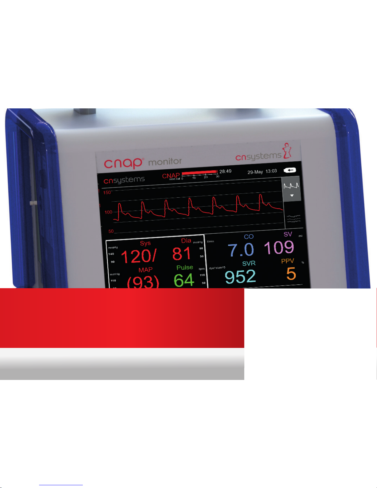
CNAP® MONITOR 500 “HD“
QUICK GUIDE
Version 07/2016 | V1.5.5 ENThis Quick Guide DOES NOT REPLACE the user manual!
Page 2
SET UP
MEASUREMENT
FAQs
CONTENT
NAVIGATION
FUNCTIONS:
FAST ACCESS
2
Page 3

Hemodynamic Parameters...................................................................................5
Measurement Select Measurement Mode / Start Measurement...................16
Started Measurement: Perfusion Index / Signal Quality.........17
Choose Patient Category / Enter Biometric Data....................18
Stop / Resume Measurement...................................................19
Set Up Checklist for fast Set Up.............................................................6
Power Up CNAP® Monitor.......................................................... 7
Prepare CNAP
®
Monitor for Measurement - Components................8
Prepare CNAP
®
Monitor for Measurement - Connections...................9
Connecting to a Patient Monitor.............................................10
Zeroing of CNAP® and patient monitor...................................11
Overview CNAP® Monitor Patient Set Up ...............................12
Choose correct CNAP
®
finger sensor size.................................13
Place CNAP
®
finger sensor and CNAP® Controller...................14
Place NBP Cuff ..........................................................................15
Navigation Navigation Frames....................................................................20
Function of Navigation Frames................................................21
3
Page 4
CONTENT
4
Main Keys and Status Indicators.............................................23
The “SETUP“ Key......................................................................25
Calibration Modes: Function / Benefits.................................. 26
Triggering A Manual NBP - Fast Access...................................27
When is it recommended to trigger a manual NBP?.............28
“Change Finger“ manually......................................................29
Functions Fast Access
FAQs: 1. How can I change alarm settings for current measurement?......31
2. How can I change alarm settings permanently?...........................32
3. Enabling hemodynamic parameters for a measurement?...........33
4. How can I improve measurement quality?....................................34
5. How can I adjust trend, signal and time settings?........................35
6. The battery?....................................................................................36
7. Service intervals for the CNAP® Monitor? ....................................37
8. What to do if CNAP® needs service ?............................................38
9. SERVICE HOTLINE ?.........................................................................39
10. Where can I get additional information?......................................40
11. How can I contact CNSystems directly? .........................................41
Page 5
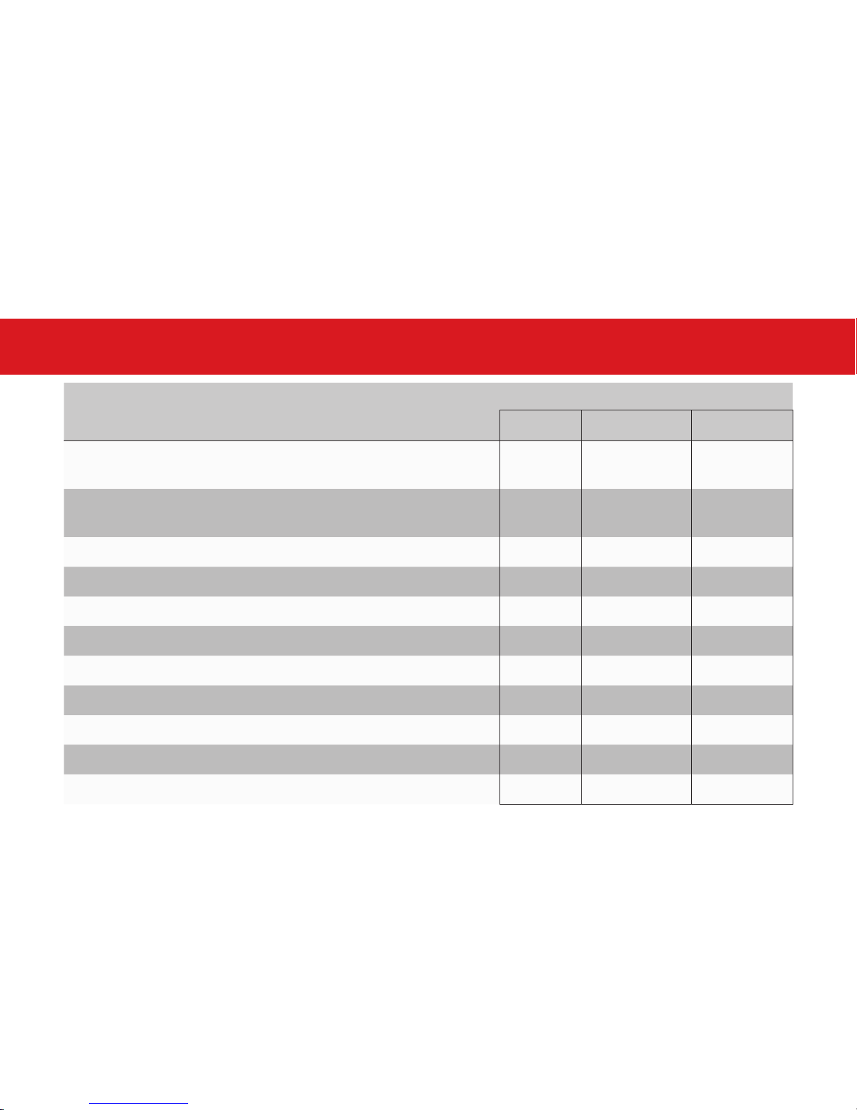
HEMODYNAMIC PARAMETERS
CNAP® Monitor Measurement Type
BP BP + PPV BP + HD
CNAP
®
continuous noninvasive arterial pressure, sys,
dia, mean
x x x
NBP
noninvasive oscillometric blood pressure
sys, dia
x x x
Pulse
pulse rate
x x x
PPV
pulse pressure variation
x x
SVV
stroke volume variation
x
CO
continuous noninvasive cardiac output
x
CI
cardiac index
x
SV
stroke volume
x
SVI
stroke volume index
x
SVR
systemic vascular resistance
x
SVRI
systemic vascular resistance index
x
5
Page 6

SET UP CHECKLIST
SET UP
6
CHECKLIST
STEP 1
STEP 3
STEP 4
STEP 5
STEP 6
STEP 7
STEP 2
Start the device and connect the CNAP® Controller Cable (orange connectors)
to CNAP® Monitor and CNAP® Controller (see also p.7,9)
Select the right NBP cuff size for the patient using the indicator on the inside of
the NBP cuff and connect the black hose to the CNAP® Monitor. (see p.15)
Fit the NBP cuff on the patient‘s upper arm. The NBP cuff can be placed
ipsilaterally or contralaterally to the CNAP® finger sensor. (see p.15)
Use the indicator on the CNAP
®
Controller to find the correct CNAP® finger
sensor size for the patient. (see p. 13)
Slide the finger sensor over two neighbouring fingers, and fix the CNAP
®
Controller on the forearm using the Velcro fixation cuff. (see p. 14)
Be sure that the CNAP
®
Controller is in the center of the forearm cuff so
that the patient can freely bend his / her wrist. (see p.14)
Start measurement by clicking “Start New Measurement“. Choose patient
category “Adult“ or “Pediatric“. (see p.16, 18)
During CNAP ® initialisation the patient needs to be in a stable position.
During general anesthesia start CNAP ® before or after the induction phase!
ATTENTION
!
Page 7
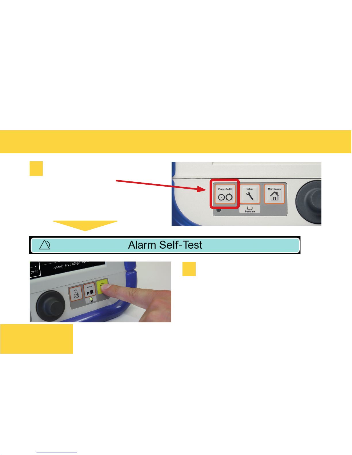
Press POWER ON / OFF
button
When alarm sounds,
confirm by pressing the
yellow alarm button.
POWER UP CNAP® MONITOR
1
2
7
SET UP
Page 8
PREPARE CNAP® MONITOR FOR MEASUREMENT
SET UP
8
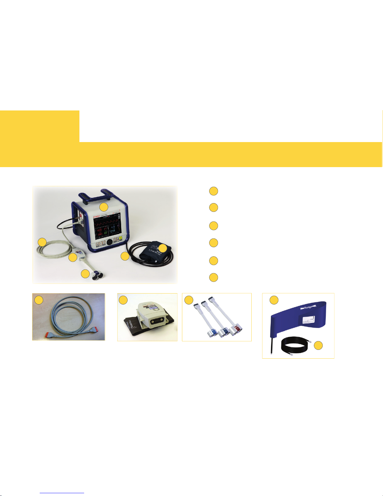
COMPONENTS
1
4
2
5
3
6
1
4
2
5
3
6
CNAP® Monitor
CNAP
®
Controller
CNAP
®
Finger sensor
NBP Cuff
NBP Air hose
CNAP
®
Controller Cable
3
6
5
2 4
Page 9
PREPARE CNAP
®
MONITOR FOR MEASUREMENT
SET UP
9
CONNECTIONS
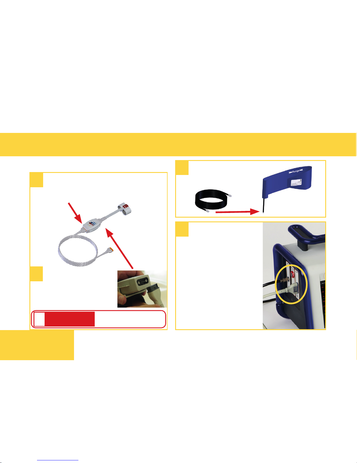
Connect the controller cable to
the orange connector of the
CNAP ® Controller.
1
2
Connect finger
sensor to black
connection of
CNAP ® Controller.
Connect NBP air
hose to NBP Cuff
3
4
Connect the
NBP air hose and the
CNAP ® Controller
cable to the CNAP ®
Monitor.
Plug in straight, not
tilted!
ATTENTION
!
Page 10
CONNECTING TO A PATIENT MONITOR
SET UP
10
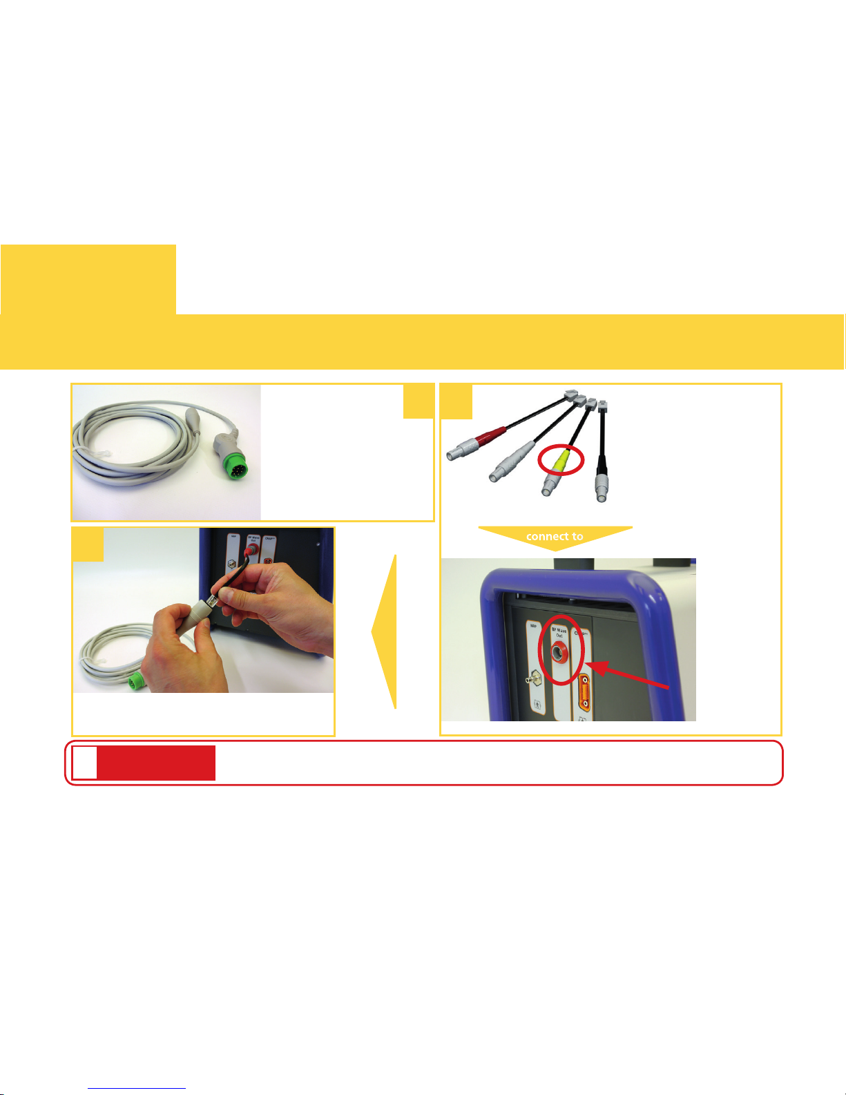
Connect Transducer cable and
patient monitor interface cable.
Prepare patient
3
1
Interface cable
Transducer Cable
Select right color from
list in user manual
(Chapter 4-5-2) and
connect it to the BP
wave out port on the
CNAP ® Monitor.
connect to
Zeroing neccessary! (see next page)
ATTENTION
!
BP Wave
Out port
monitor Interface Cable
and connect it to the
arterial port of your
patient monitor.
2
Page 11
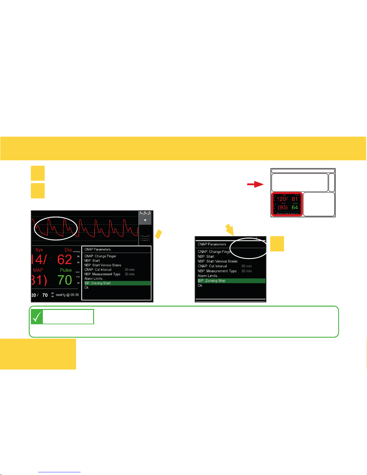
ZEROING OF CNAP® AND PATIENT MONITOR
Go to parameter frame on CNAP ® Monitor: *click*
*click*
*click*
1
2
Select IBP: Zeroing Start - *click*
*click*
Z
e
r
o
i
n
g
o
f
p
a
t
i
e
n
t
m
o
n
i
t
o
r
11
Stop Zeroing
on CNAP ®:
Select IBP:
Zeroing Stop
- *click*
3
then zero transducer on patient monitor
CNAP ® Zeroing is automatically active when the CNAP
®
Monitor is on and connected to the patient monitor but no
measurement has been started so far.
TIP
SET UP
Page 12
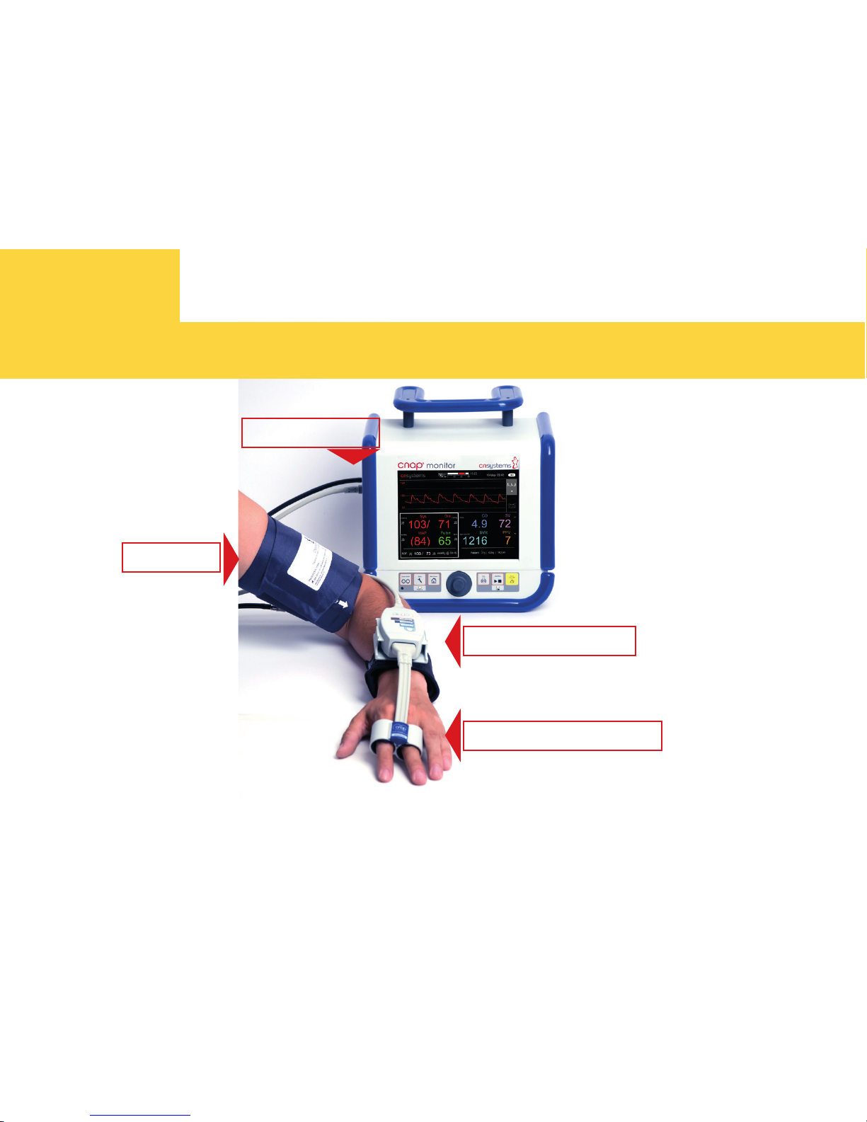
OVERVIEW: PATIENT SET UP
NBP Cuff
CNAP® Controller
Connections
CNAP® Finger sensor
SET UP
12
Page 13
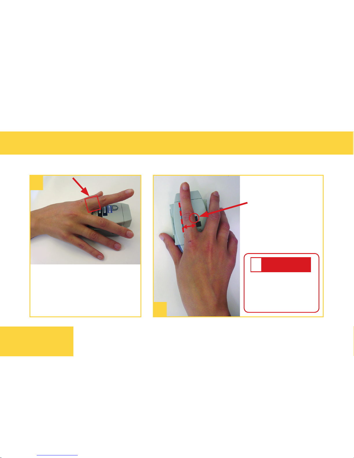
STEP 1. CHOOSE CORRECT CNAP
®
FINGER SENSOR SIZE
AVAILABLE SIZES: small, medium or large
Put proximal phalanx of
index finger on indicator
of CNAP ® Controller align
with the grey line on the
left.
Choose the sensor
size indicated
on the shortest
bar which is still
visible.
1
2
Always choose the
larger sensor if you
are in doubt about
the size!
ATTENTION
!
B
13
SET UP
2
1
Page 14
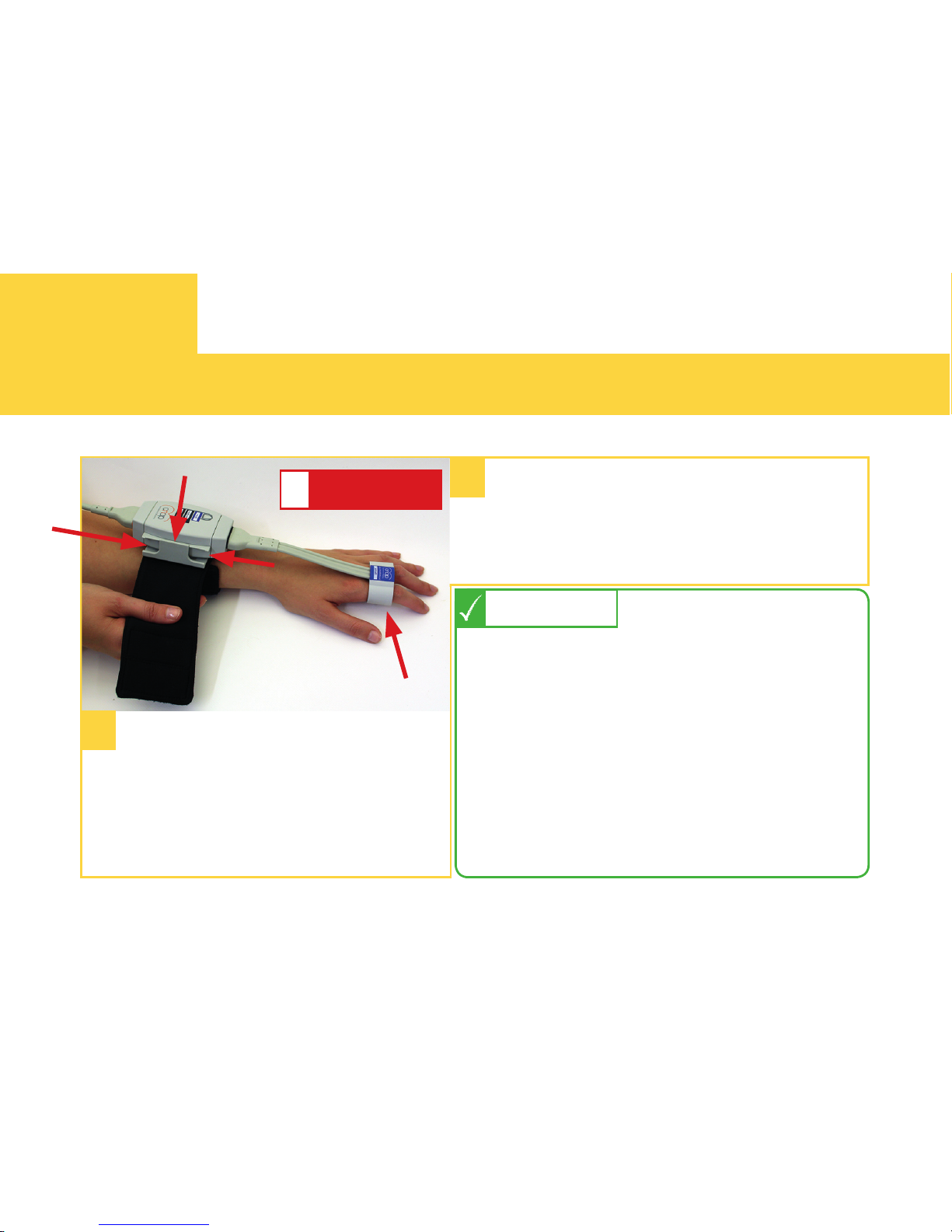
STEP 2. PLACE CNAP® FINGER SENSOR AND CNAP® CONTROLLER
14
SET UP
Make sure that the
CNAP ® Controller is placed in
central position of the slide
and fix the strap.
Slide the finger sensor over two
neighbouring fingers, make sure
that it is not placed on the finger
joints!
1
2
ATTENTION
!
slide back fully!
12 hours before lifetime expiration
of the finger sensor a message
appears. It automatically disappears
and does not affect measurements.
Please make sure to contact your
local distributor in time for a new
sensor.
NOTE
See also:
Operators Manual – chapter 16.1
Page 15
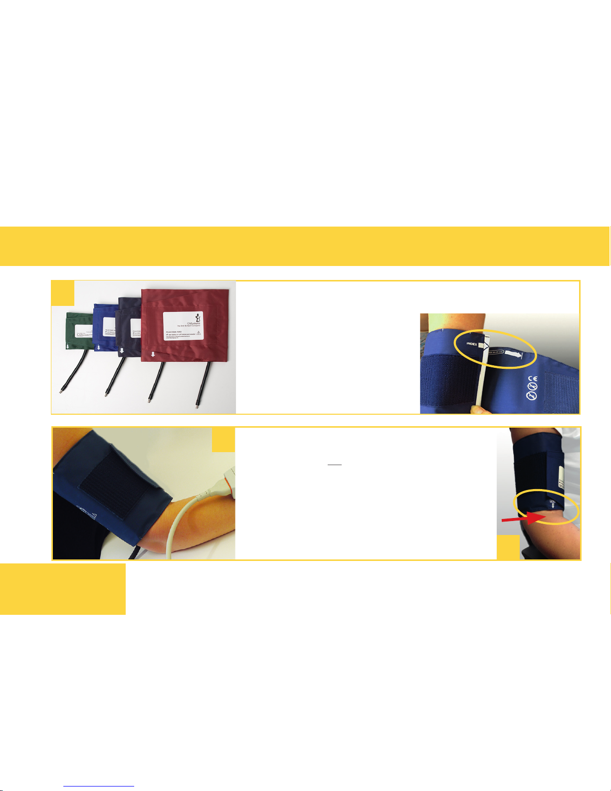
STEP 3. PLACE NBP CUFF
SET UP
Fasten NBP cuff on the upper arm
(ipsilaterally or contralaterally to
arm with fingersensor).
Align marker (white arrow) with
the brachial artery in the crook of
the arm.
Choose the right NBP cuff from 4 different sizes
2
1
15
by using the size indicator
on the inside of the cuff.
See also:
Operators Manual –
chapters 3.2.3 and 10.
3
Page 16
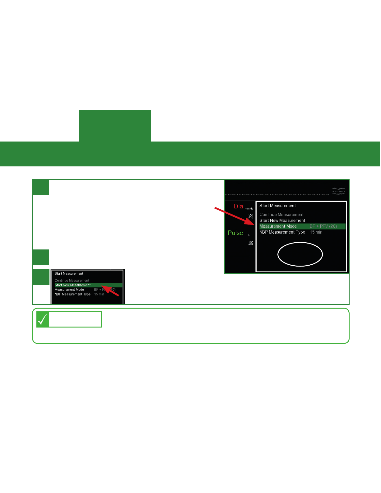
Once the patient set up is completed,
select the measurement mode in the
pop-up menu from three options:
> BP only
> BP + PPV
> BP + HD (full hemodynamics)
1
BP + PPV and BP + HD must be enabled to be selectable.
Contact your distributor for a licence key if you cannot
select these options.
NOTE
SELECT MEASUREMENT MODE / START MEASUREMENT
MEASUREMENT
Confirm by clicking the wheel.
*click*
16
2
3
To start the
measurement, select “Start New Measurement“ and
confirm with the click wheel.
Page 17
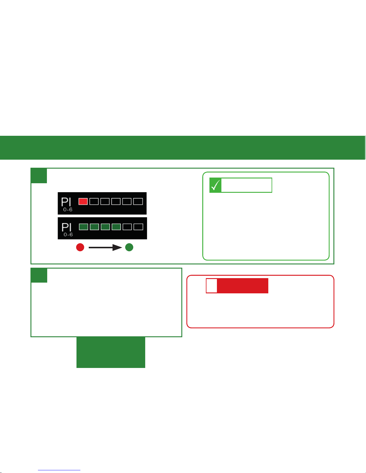
If perfusion is poor (=red), try
pushing the finger sensor to the
back of the finger, warming the
hand (use exam glove or towel),
changing finger sensor size, or
changing hands.
TIP
MEASUREMENT
STARTED MEASUREMENT
no signal good perfusion
17
Once measurement has started, finger
sensor checks perfusion index (PI):
1
2
At the same time menu window
opens for choosing patient category and for entering biometric
data (see next page).
Calibration to NBP reference
value also takes place.
•
Keep patient still, do not move
hand!
•
No changes in body posture!
ATTENTION
!
Page 18
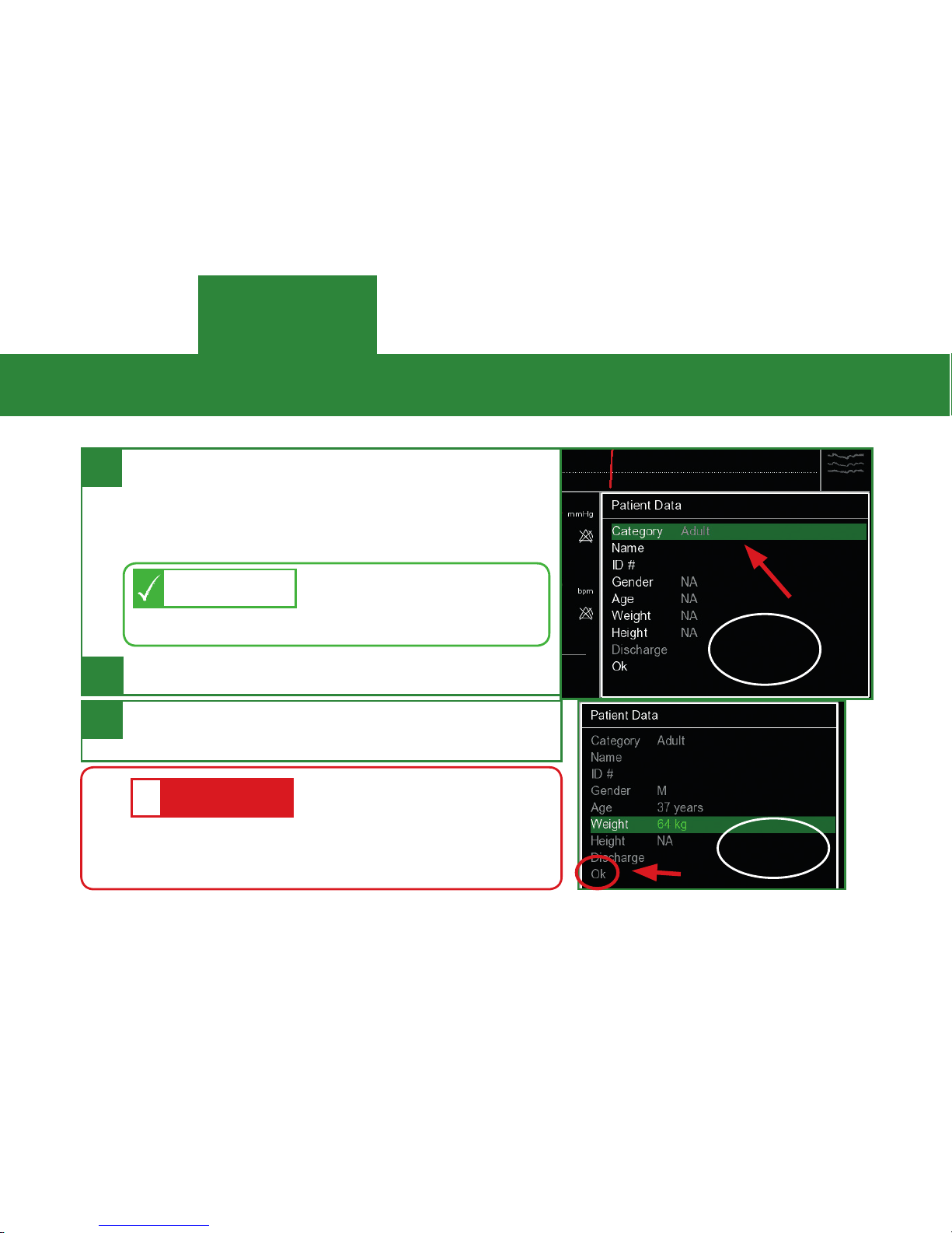
Choose patient category (Adult or Pediatric) in the pop-up menu and enter
biometric patient data (for full hemodynamics).
1
This is important as
alarm ranges and NBP
NOTE
inflation pressure are different!
CHOOSE PATIENT CATEGORY AND ENTER BIOMETRIC DATA
MEASUREMENT
Confirm with “ok“ by clicking the wheel.
Calculation of hemodynamic parameters
starts; display after a few seconds.
*click*
*click*
18
2
3
Before starting any
interventions, make sure
ATTENTION
!
that the calibration has been completed: numerical
values should not have gray background anymore!
Page 19
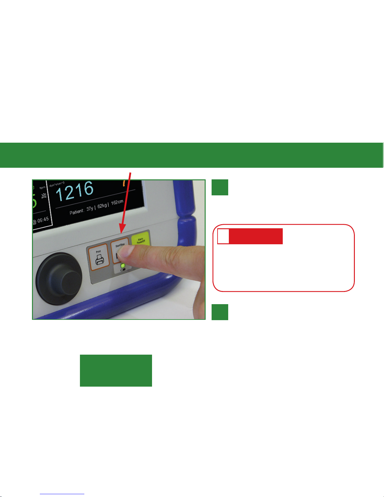
STOP / RESUME MEASUREMENT
Press the Start/Stop Button
to STOP measurement (e.g.
when finished or to readjust
set-up).
RESUME a measurement
with the Start/Stop Button
(e.g. after readjusting set-up,
patient transfer, etc.) Patient
data remain displayed!
Do not remove the
CNAP
®
finger sensor when
measurement is still in progress!
STOP MEASUREMENT FIRST!
ATTENTION
!
19
1
2
MEASUREMENT
Page 20
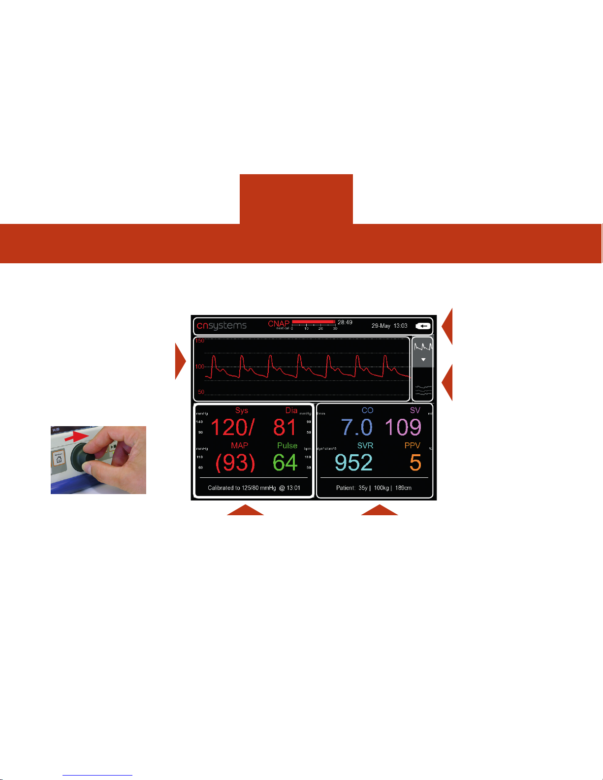
NAVIGATION FRAMES
Alarm frame
Signal and
Trend View
selector frame
Hemodynamic
frame
Signal & Trend
frame
Parameter frame
(= default)
clickwheel
*turn*
*click*
20
The monitor has a clickwheel and 5 different “frames“ on the screen to access all menus / functions.
NAVIGATION
Page 21
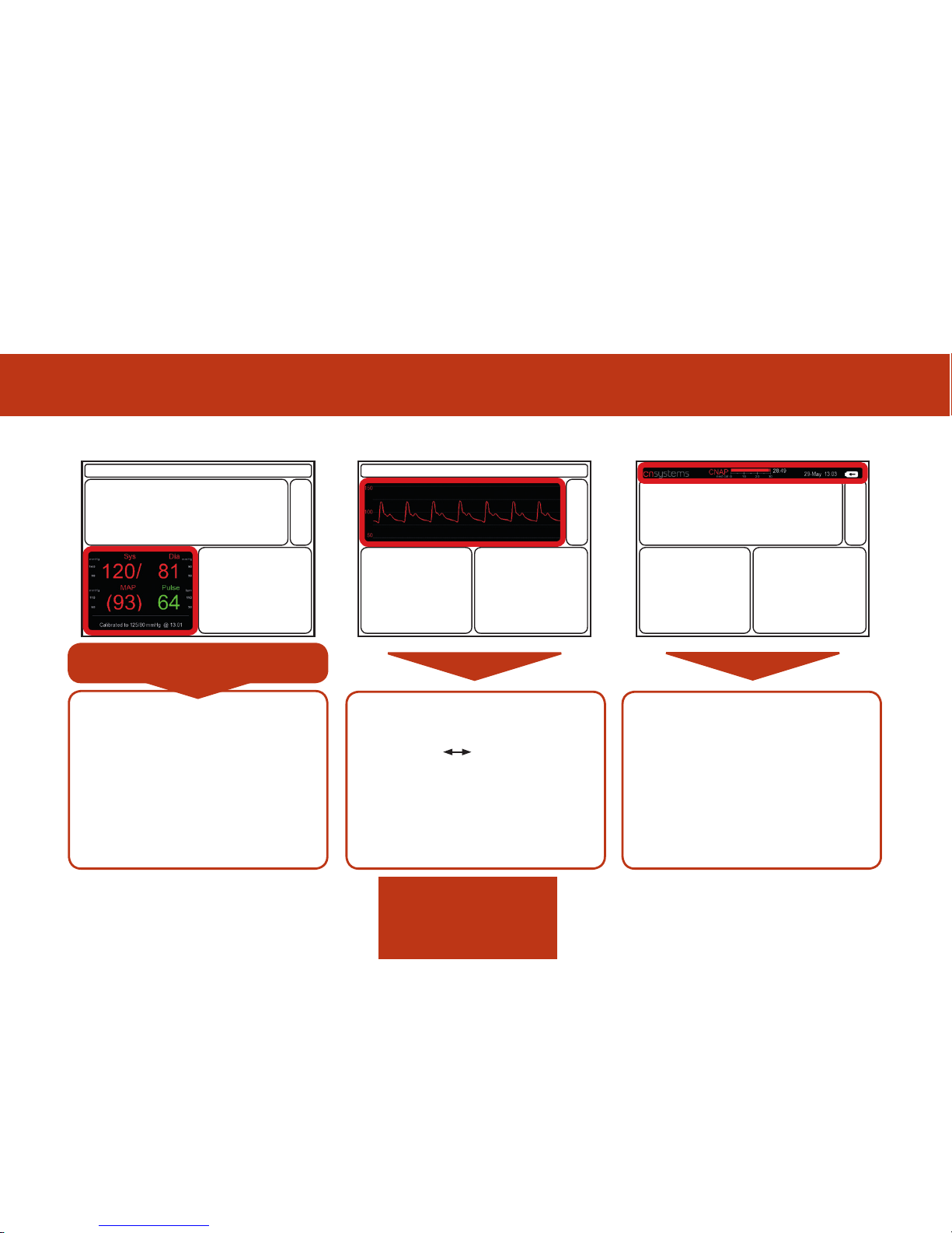
FUNCTION OF NAVIGATION FRAMES
> manual NBP triggering
> manual finger change
> finger change interval setting
> alarm settings
> zeroing of IBP port
> NBP measurement type
> intervention setting
> change of trend view
(graphic numeric)
> scaling of trend curve
> selection of trending
parameters (up to 2 additional)
> change of time range
> display of alarm and
status messages
> direct access to alarm
settings as long as alarm
message is visible
> display of battery status,
date, next finger change,
next NBP measurement
Signal & Trend frameParameter frame Alarm & Status frame
This is the default frame!
21
NAVIGATION
Page 22
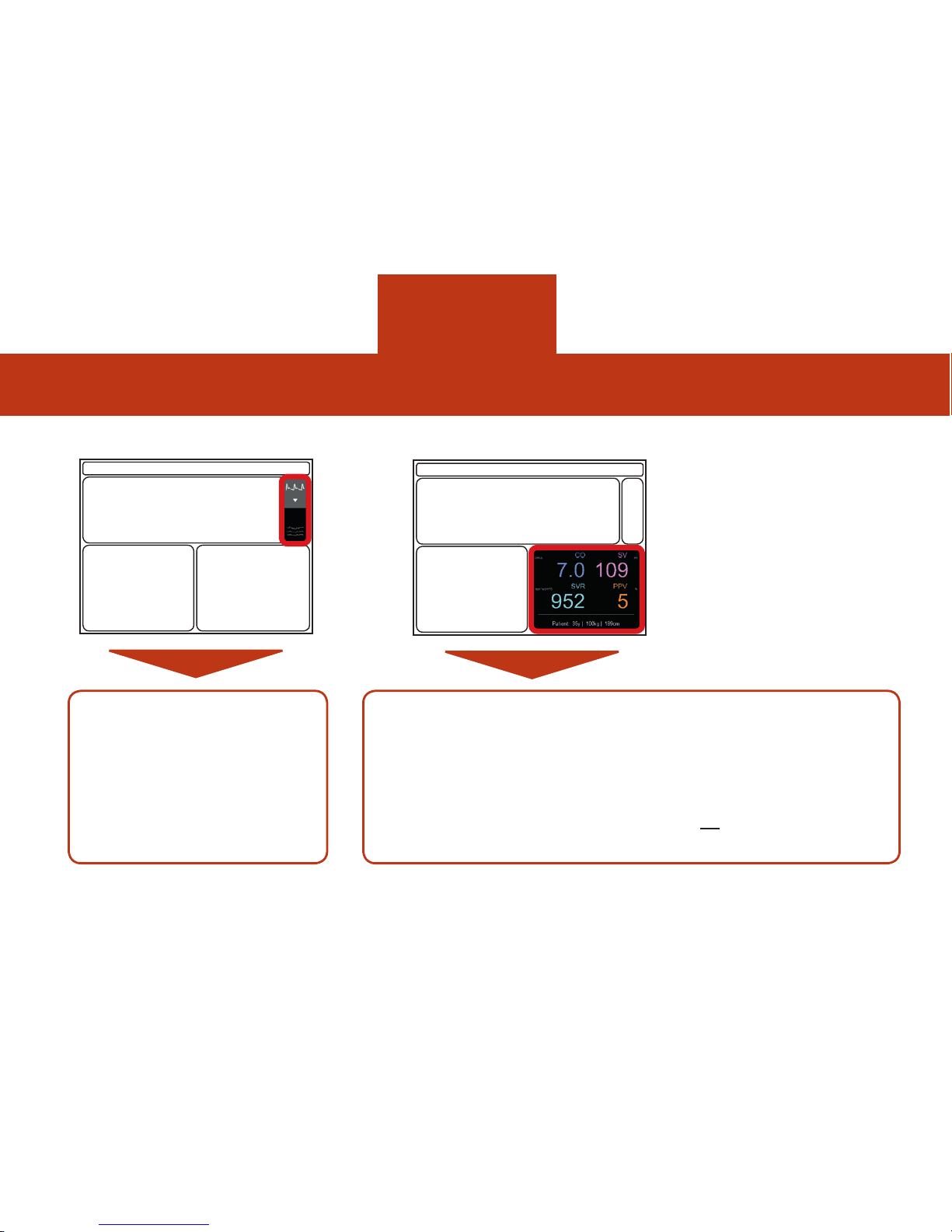
FUNCTION OF NAVIGATION FRAMES
22
NAVIGATION
> switch between signal
view and parameter trends
Hemodynamic frameSignal & Trend View Selector
> activating/ deactivating HD
> manual entry or change of
patient data
> discharging of patient (data of
current measurement are deleted for
measurement with new patient)
> changes between absolute
and indexed values
> manual entry of external
CO value for calibration
> selection Fluid Parameter
PPV or SVV
> manual entry of CVP
Page 23
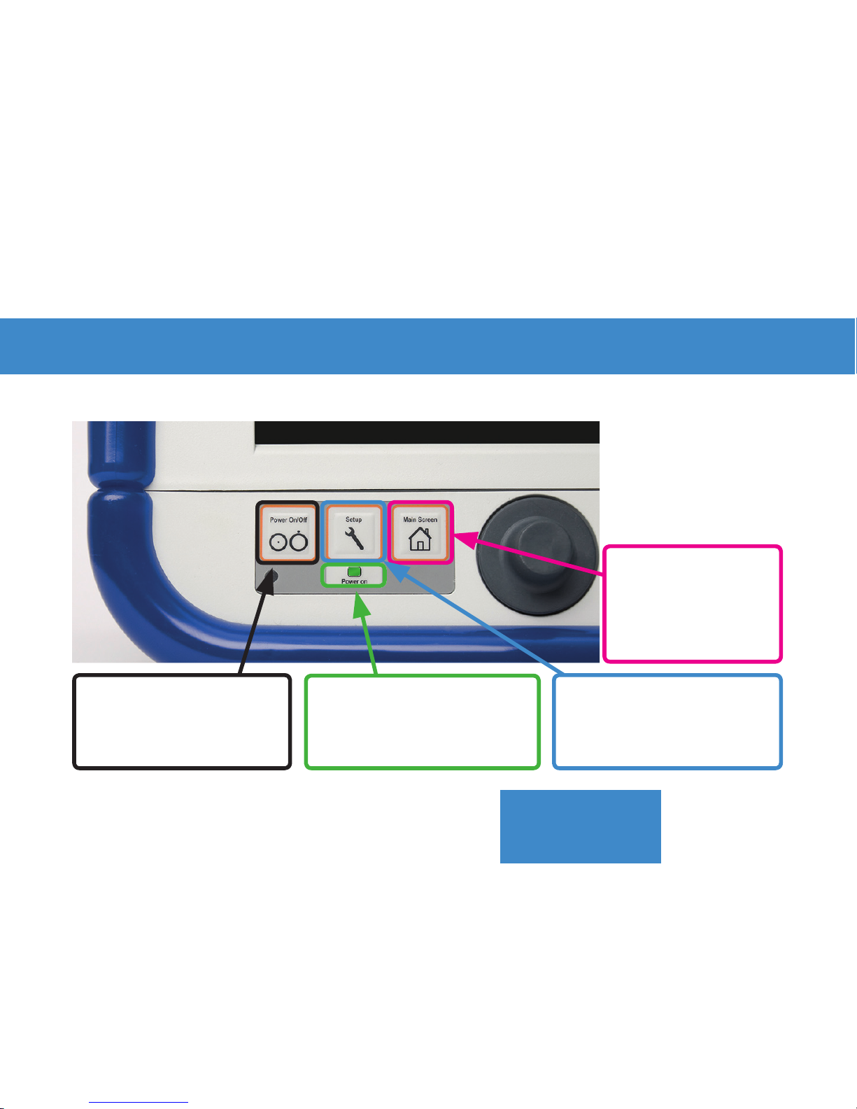
SETUP:
access to configuration
menu
MAIN KEYS FOR FAST ACCESS
FAST ACCESS KEYS and STATUS INDICATORS
POWER ON / OFF:
hold for 2 seconds to
power on/off.
MAIN SCREEN:
return to main
screen from any
submenu
power “on“ indicator:
>
green: switched on
>
orange: system error
23
FUNCTIONS
Page 24
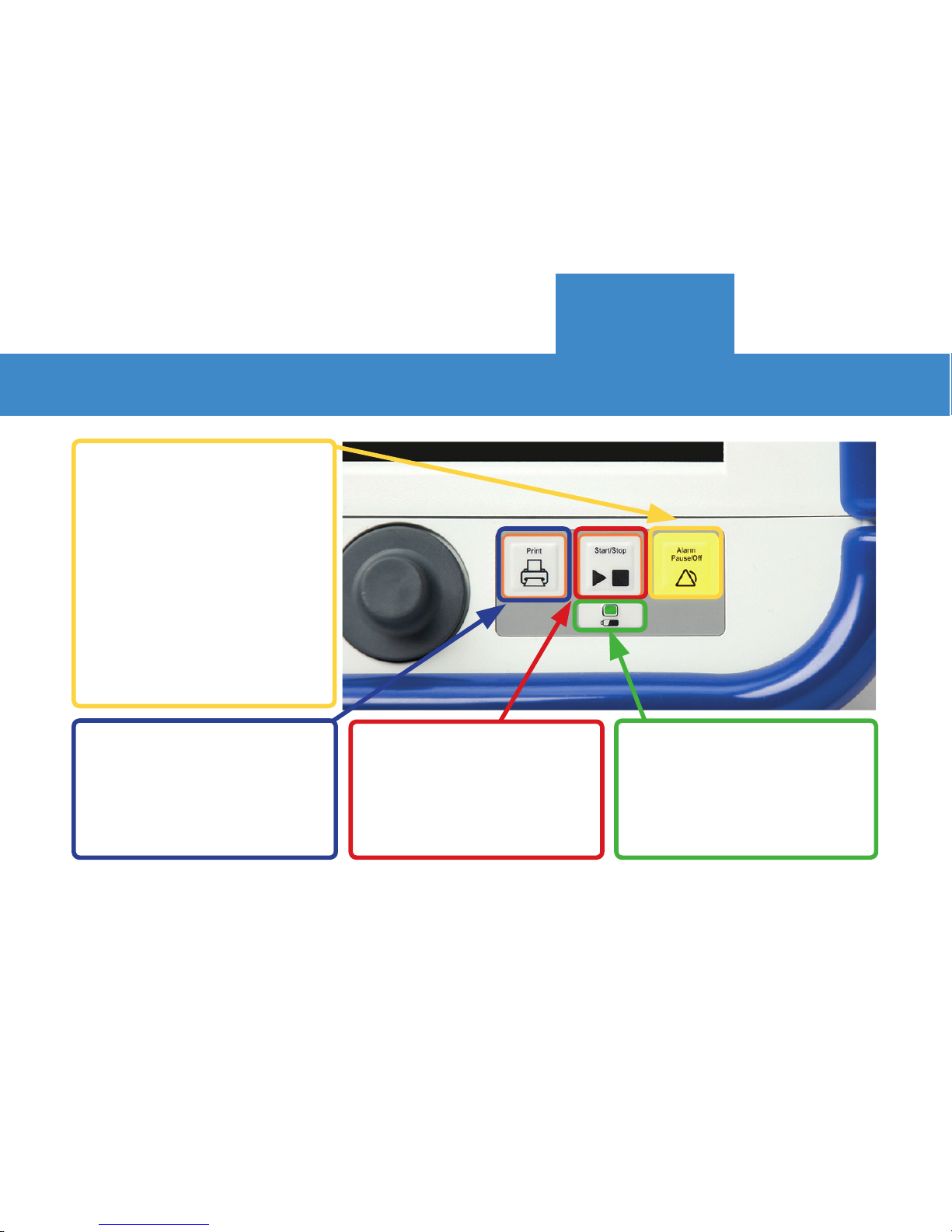
MAIN KEYS FOR FAST ACCESS
PRINTING START/ STOP:
>
press once: print blood
pressure curve
>
press and hold for one
second: print trend view
START/ STOP:
>
stop and resume
measurement
ALARM PAUSE/ OFF:
alarm functions control:
>
Press once: alarm
acknowledgement
>
Press twice: set alarm
to pause / off
>
Press three times:
re-activate alarm function
Battery charge status:
>
green = ok
>
orange = less than 25%
>
red = l
ess than15 minutes
left!
24
FUNCTIONS
Page 25
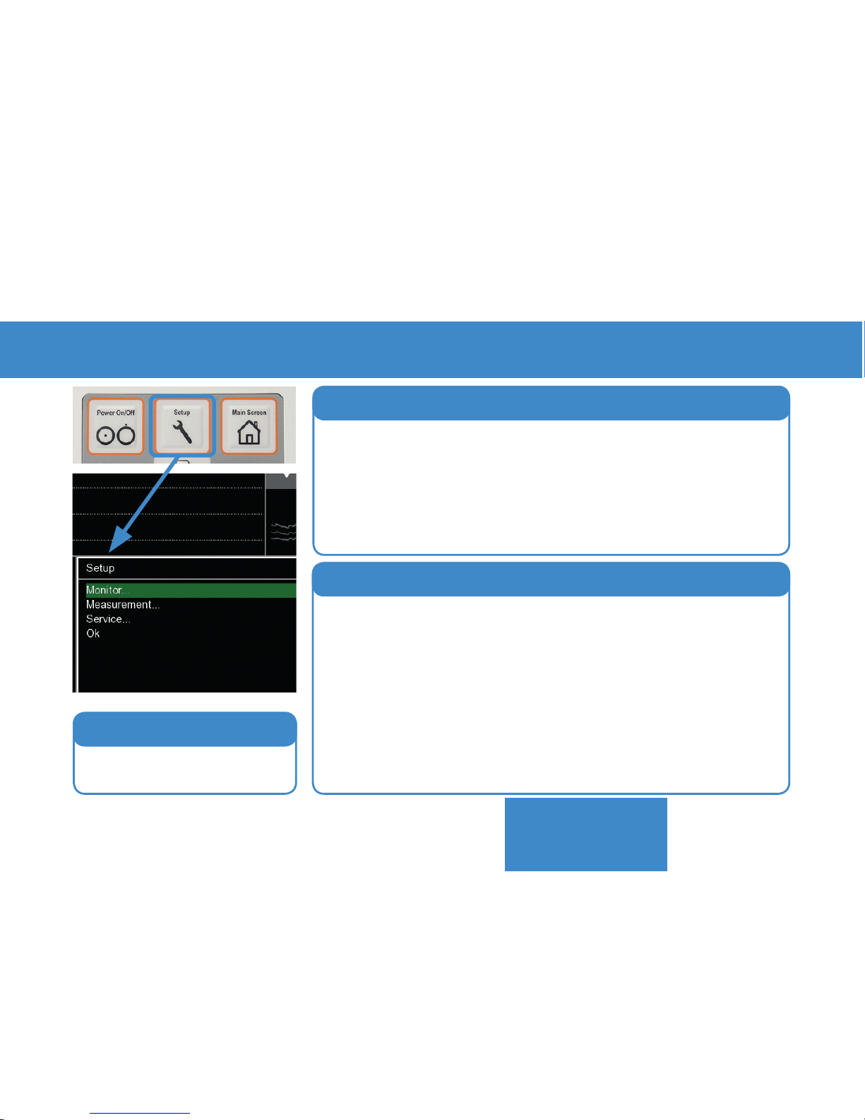
THE “SET UP“ KEY
For service purposes
only!
3. Service Settings
> NBP Mode: select calibration mode (see next page)
> NBP Interval
> CNAP Calibr. Interval
> Hemodynamic (on/off, change settings)
> Display Options: Interventions, Views, Scales,etc.
> Trend Parameters: select parameters to be displayed in the trend view
> Print options
> Parameter averaging
> Patient category
2. Measurement Settings
> Change Language / Time / Date
> En-/ disable device features:
PPV, HD, Record, Analog Out, enter licence keys, etc.
> Recording on/off (if activated)
> Switch between Metric / US customary units
> Access PPU measurement statistics
1. Monitor Settings
25
FUNCTIONS
Page 26
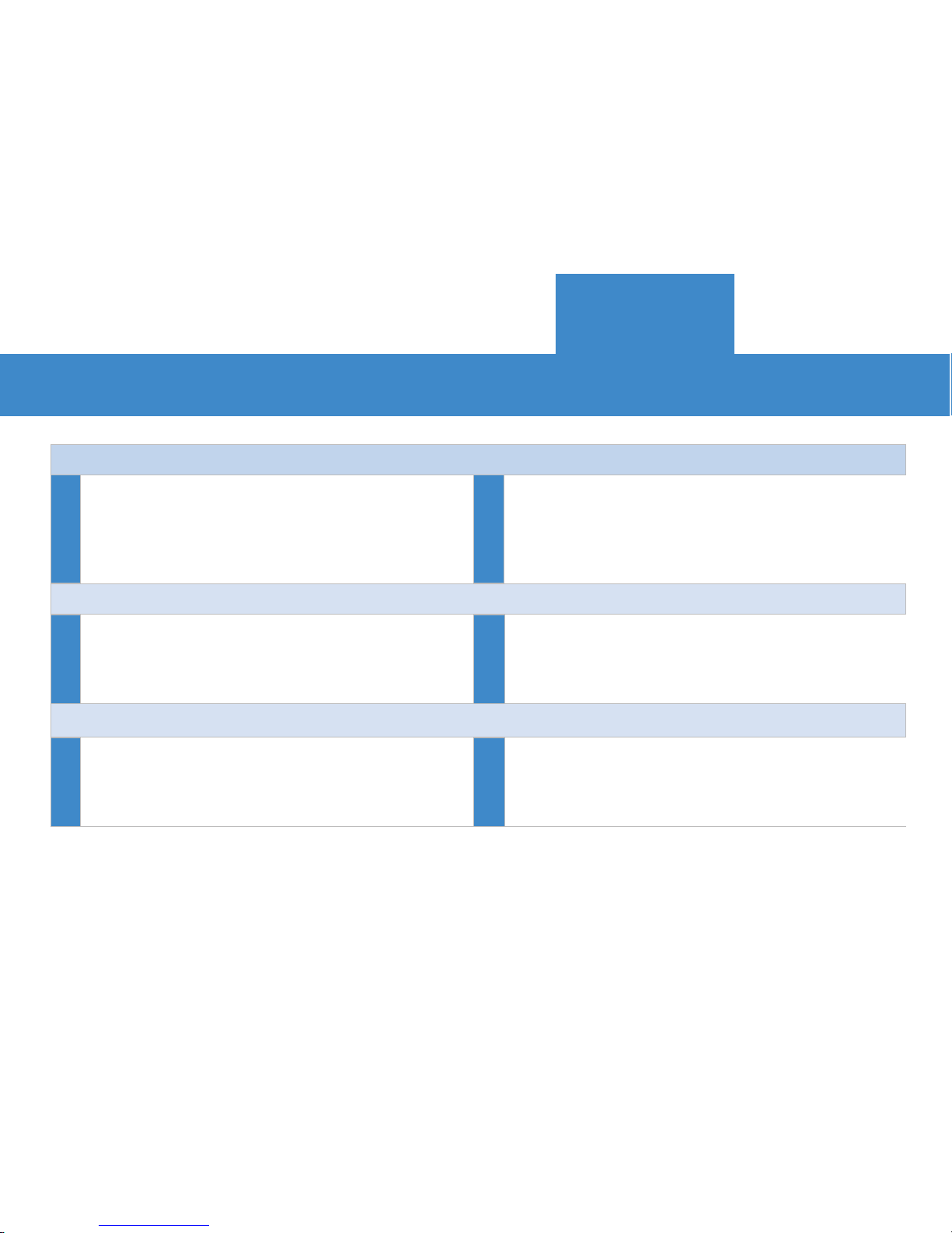
CALIBRATION MODES
26
AUTOMATIC NBP CALIBRATION: “INTERNAL“ (= DEFAULT)
Calibration to automatic NBP measurements triggered by the integrated NBP module in adjustable
intervals between 5-60 minutes. Can be stopped
any time by pressing Start/Stop Button.
This is the default mode delivering absolute values
automatically as long as no other blood pressure
reference value (NBP or IBP) is entered manually
(see also: external calibration mode).
MANUAL BP CALIBRATION: “EXTERNAL“
Calibration to a manually entered NBP , IBP
or height offset reference value from external
devices.
CNAP® can be operated without internal NBP
measurement calibrating to a manually entered
value for absolute BP information. Useful for special applications.
TRENDING MODE: “EMPIRIC CALIBATION“
Automatic calibration to a heart level value based
on an emipric database for bridging the short
time until CNAP® is calibrated to a measured or
externally entered NBP value.
Blood pressure curve is displayed only 10 secs after
start-up for a quick trending prior to calibration to
the directly measured reference value.
FunctionFunctionFunction
Benefit
BenefitBenefit
FUNCTIONS
Page 27
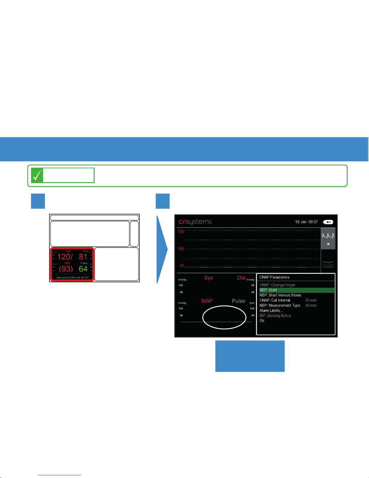
TRIGGERING A MANUAL NBP
Go to parameter frame:
*click*
1
2
Choose NBP: Start - *click*
27
Triggering a manual NBP is possible at ANY TIME in any mode!
NOTE
*click*
FUNCTIONS
Page 28
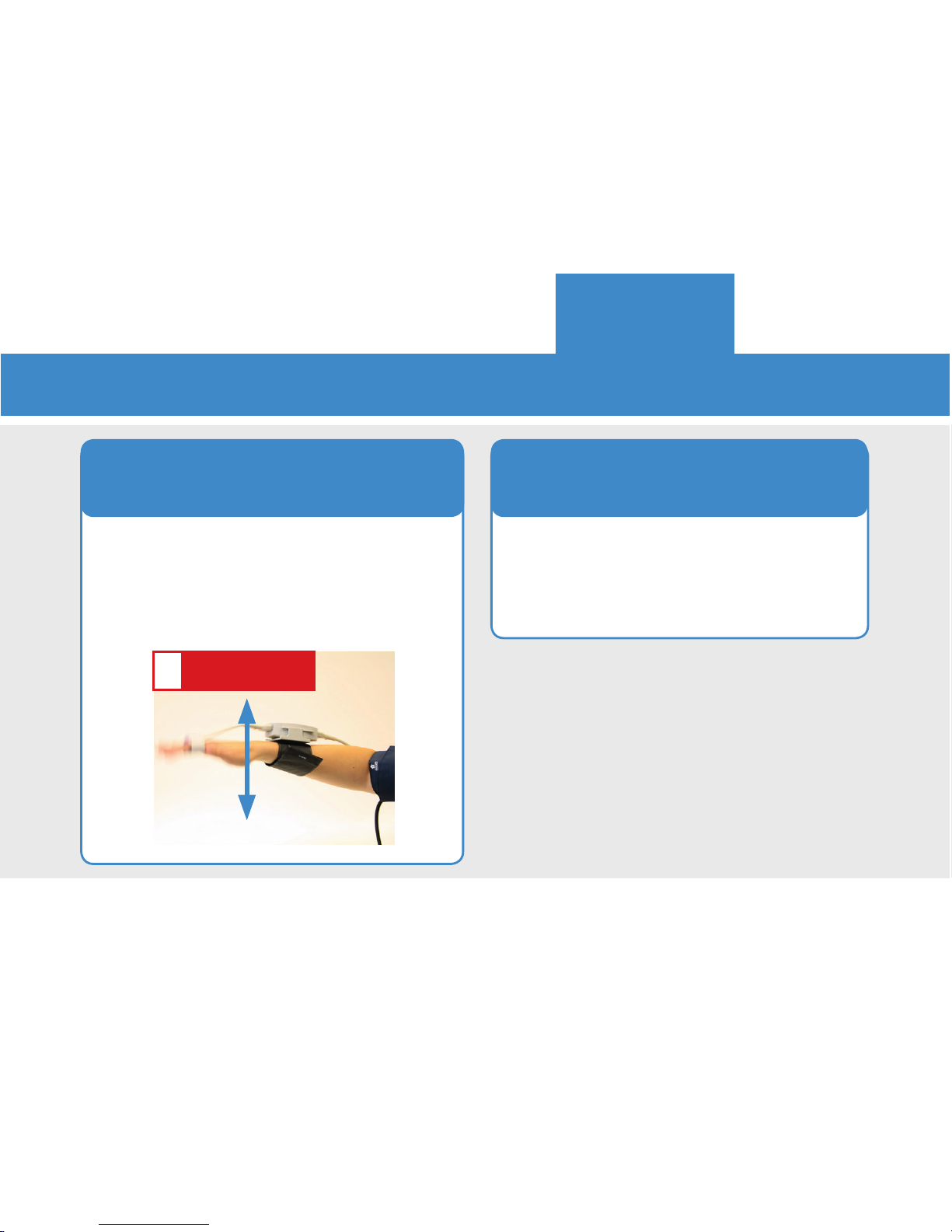
28
WHEN IS IT RECOMMENDED TO TRIGGER A MANUAL NBP ?
After an intervention or whenever
you feel that an update to the NBP
reading may be beneficial.
2. In situations that quickly
require updated calibration
Trigger a manual NBP after moving
or repositioning the patient or the
patient‘s hand or whenever hydrostratic change/ offset happens.
1. Upon hand movement
or patient repositioning
ATTENTION
!
FUNCTIONS
Page 29
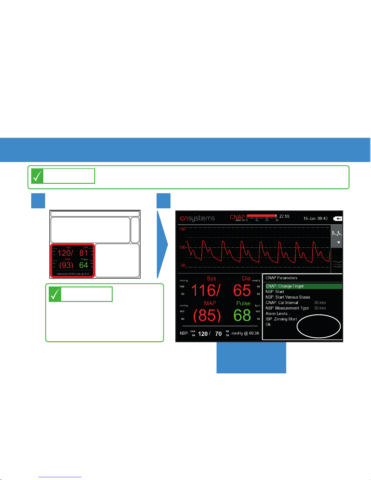
“CHANGE FINGER“ MANUALLY
Go to parameter frame:
*click*
1
2
Choose CNAP: Change Finger - *click*
29
Switching a measurement to the other finger is possible at
ANY TIME except during a NBP measurement!
NOTE
*click*
FAST ACCESS: Parameter frame
is the default frame. If not
changed, just click wheel 2
times to change finger!
TIP
FUNCTIONS
Page 30

FREQUENTLY ASKED QUESTIONS
FAQs
30
FAQs: 1. How can I change alarm settings for current measurement?......31
2. How can I change alarm settings permanently?...........................32
3. Enabling hemodynamic parameters for a measurement?...........33
4. How can I improve measurement quality?....................................34
5. How can I adjust trend, signal and time settings?........................35
6. The battery?....................................................................................36
7. Service intervals for the CNAP® Monitor? ....................................37
8. What to do if CNAP® needs service ?............................................38
9. SERVICE HOTLINE ?.........................................................................39
10. Where can I get additional information?......................................40
11. How can I contact CNSystems directly? .........................................41
Page 31
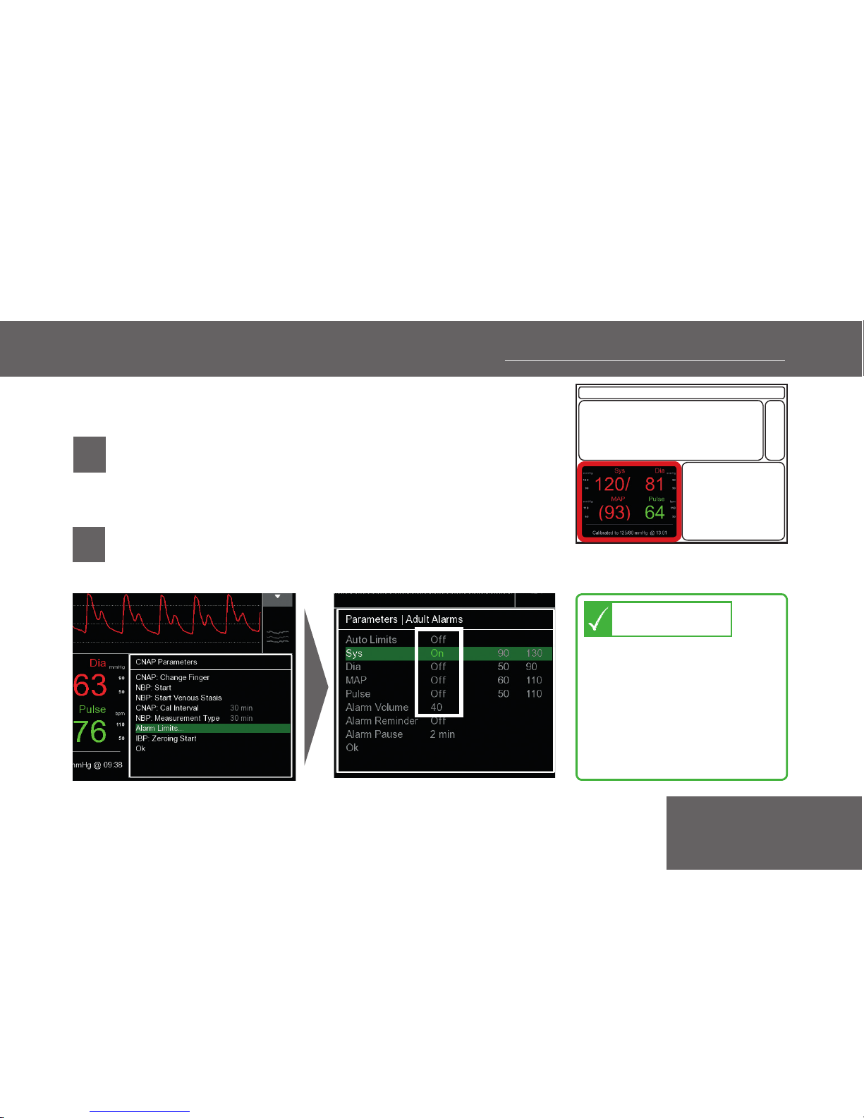
1. HOW TO CHANGE ALARM SETTINGS:
CURRENT MEASUREMENT
ALARMS OFF/ON AND CHANGE LIMITS
• Go to parameter frame with click-wheel
and *click*
• Select “Adult alarm limits“ and turn
values to
“Off“
or change limits
*click*
1
2
*click*
FAQs
31
Whenever a physiological alarm is active, the
settings can be directly
changed by clicking on
the alarm frame.
TIP
Page 32
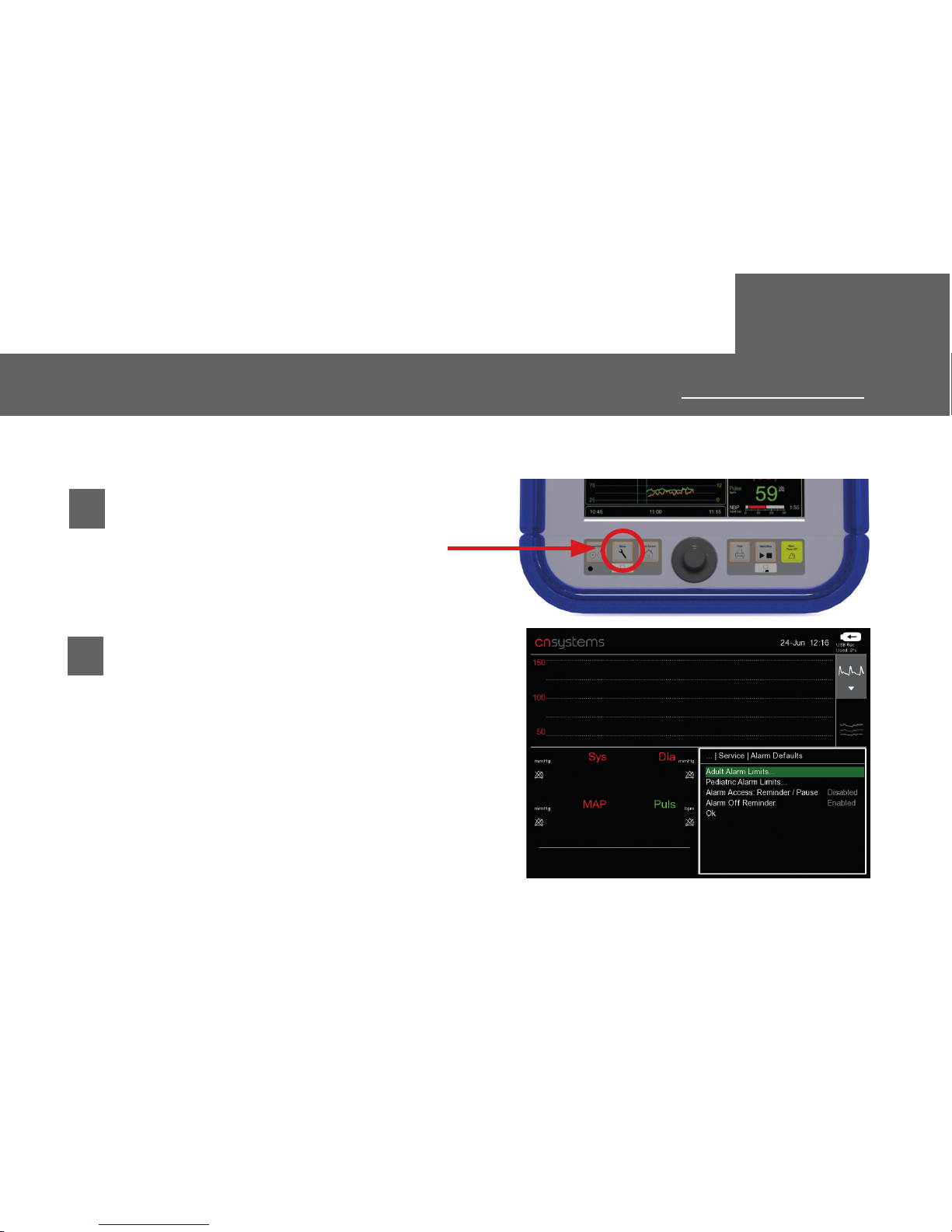
2. HOW TO CHANGE ALARM SETTINGS:
PERMANENTLY
ALARMS OFF/ON AND CHANGE LIMITS
• Press Setup key.
• Change the alarm default settings
in the submenu
Service | Alarm Defaults
(Password: 8737)
1
2
FAQs
32
Page 33
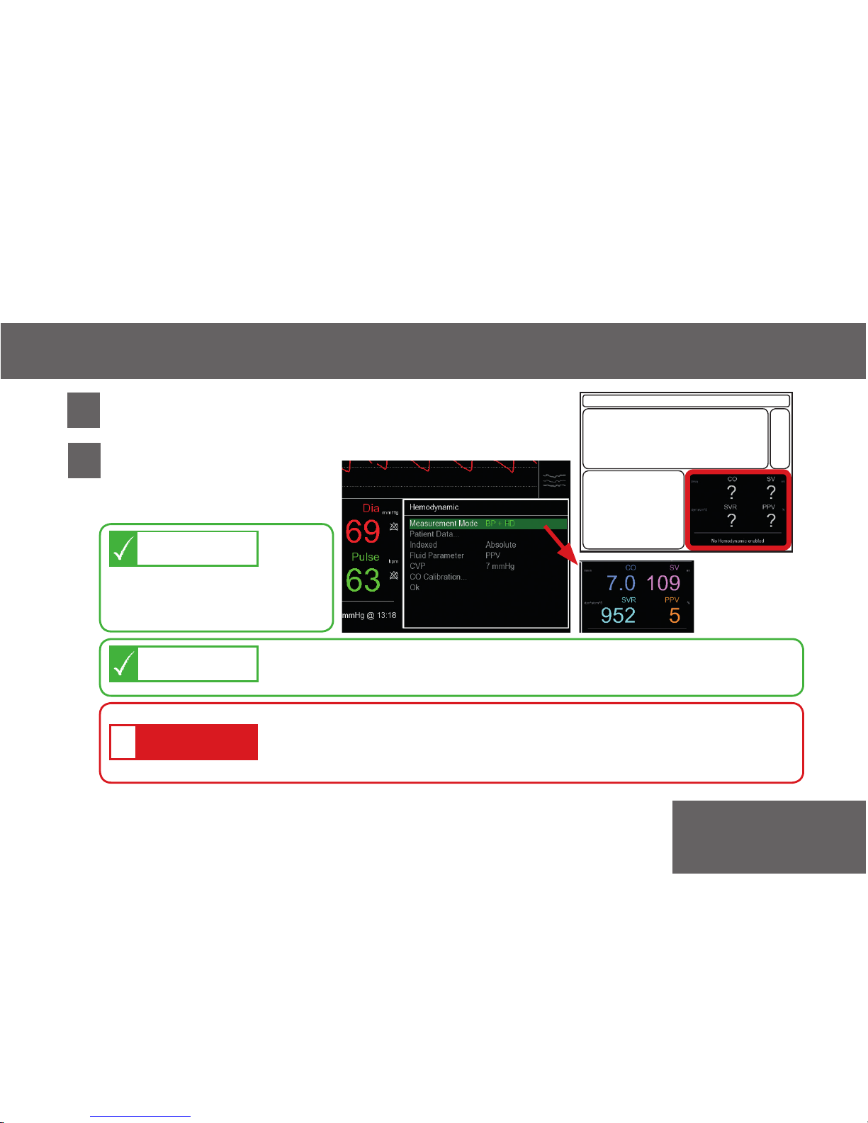
3. ENABLING HEMODYNAMIC PARAMETERS FOR A MEASUREMENT
FAQs
• If HD is not enabled, hemodynamic frame shows
question marks: select with click-wheel - *click*
1
*click*
Choose Measurement
Mode: “BP+HD“ and
confirm with“ok“.
2
If BP + HD is active,
BP + PPV is automatically
enabled.
NOTE
Hemodynamic parameters can also be set permanently in
Set Up | Measurement | Hemodynamic
TIP
Hemodynamic
parameters
visible now!
If it is not possible to enable the Hemodynamic
parameters, please request a license key from CNSystems
or your distributor.
ATTENTION
!
See also:
Operators Manual – chapters 4.4 and 12.2
33
Page 34
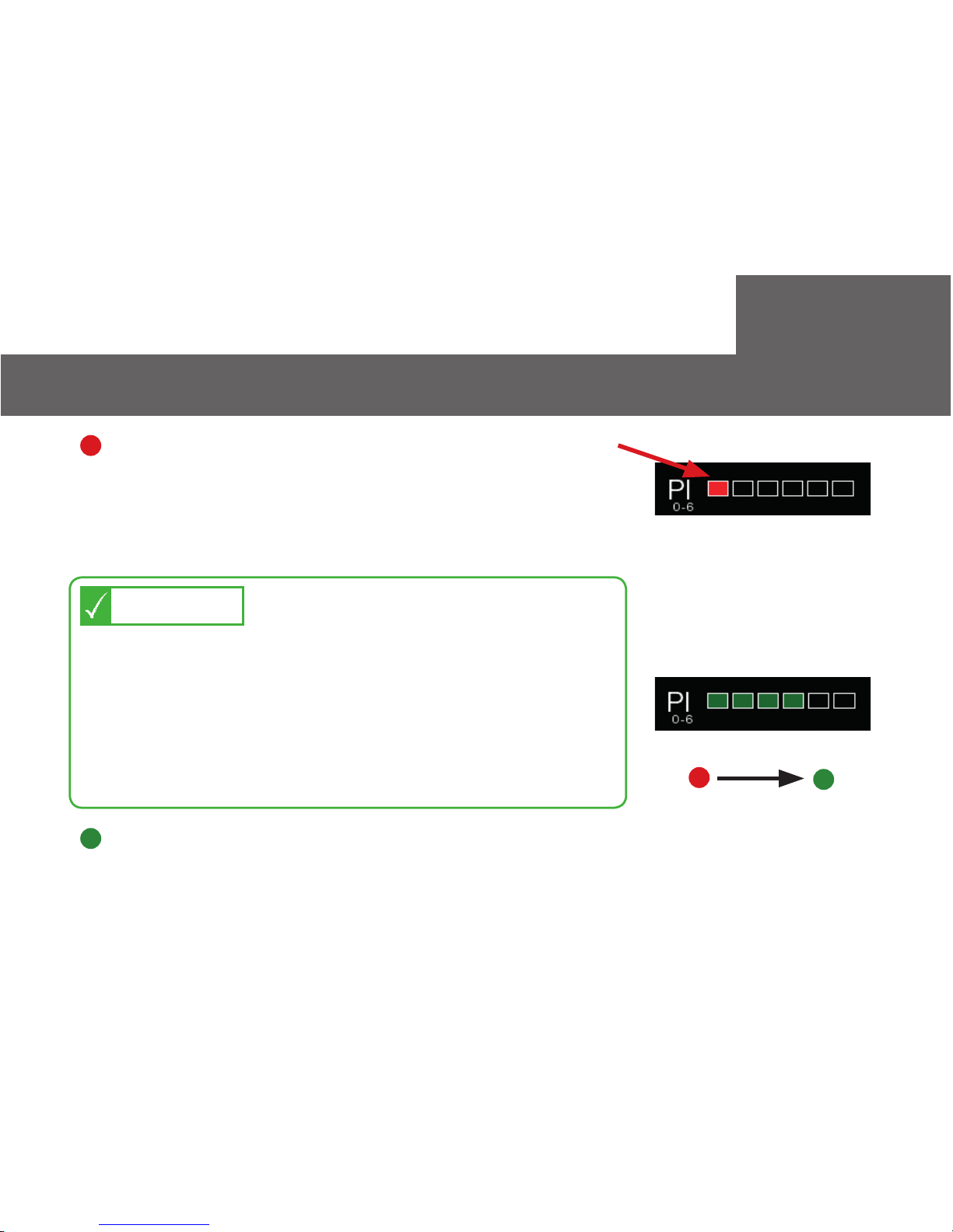
FAQs
4. HOW TO IMPROVE MEASUREMENT QUALITY
RED: no signal can be detected
GREEN: measurement starts automatically.
Reasons / limitations:
> poor peripheral perfusion (shock, severe
Raynaud‘s, hypothermia, vasoconstriction)
> edema
for improving signal quality:
>
Check position of CNAP ® finger sensor:
Do not place on finger joints!
>
Check if CNAP ® finger sensor size is correct
>
Warm up fingers to improve blood flow
(use disposable exam glove or towel)
>
Try to measure on the other hand
TIP
See also:
Operators Manual – chapter 3.7
no signal
good perfusion
34
Page 35
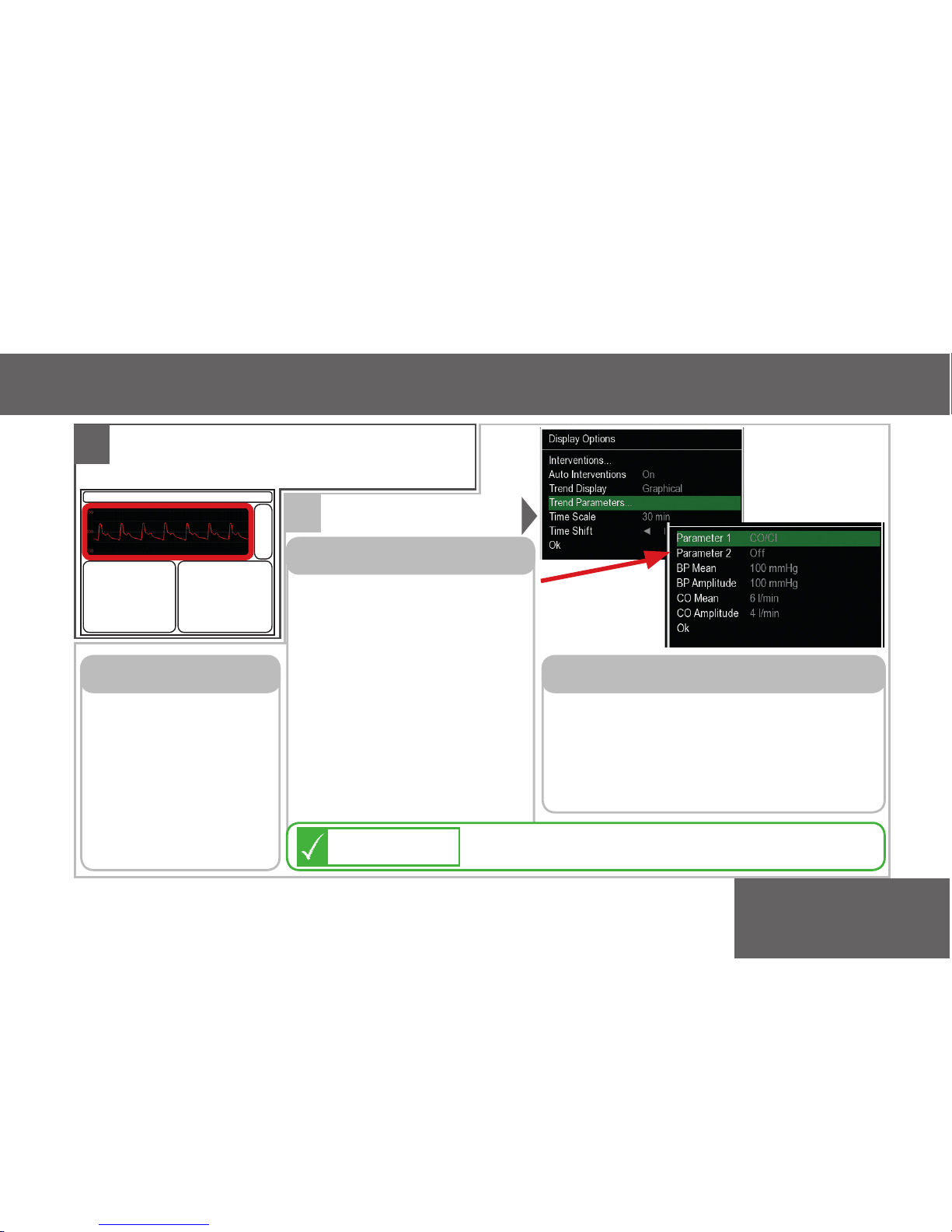
5. HOW TO ADJUST TREND SETTINGS, SIGNAL AND TIME SCALES
FAQs
2
*click*
Trend adjustments
NOTE
Trend
Menu:
For switching
> graphical,
> numerical,
> alarm history,
> Intervention
views.
TREND DISPLAY
> Adjust displayed time range
according to your needs.
> Trend navigation in time back
and forth with arrows.
TIME SCALE / TIME SHIFT
>
Parameter 1+2:
You can choose up to
2 additional para meters shown in Trend
view (SVV, PPV, CO, SV,
SVR).
> Adjust
“MEAN“
and
“AMPLITUDE“
of BP
and Pulse in case trends
are not visible within
scale range.
TREND PARAMETERS
35
Switching parameters here also causes
changes in the Hemodynamic frame!
NOTE
Go to Signal & Trend frame with
click-wheel and *click*
1
Page 36
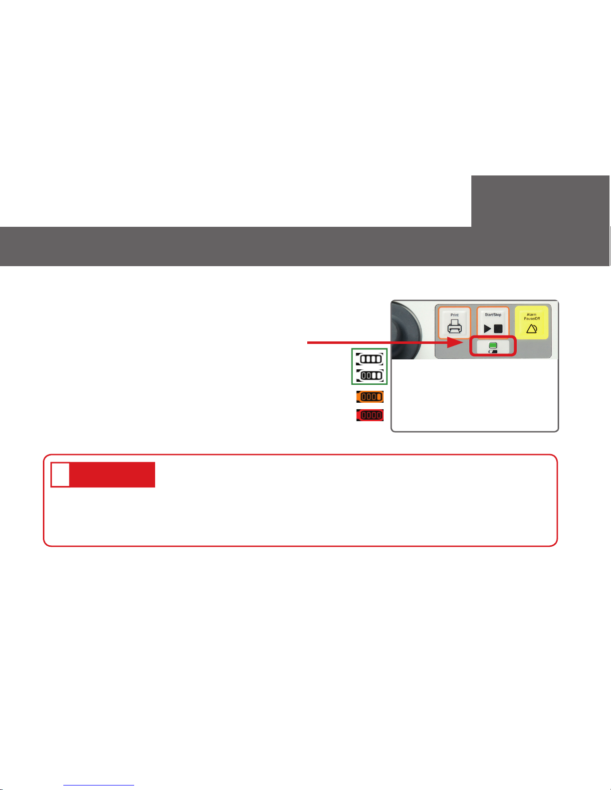
6. THE BATTERY
•
Never completely discharge the battery!
•
Immediately connect to power supply if battery charge
status is below 25%!
•
Send device to CNSystems for maintenance every 24 months.
• up to 120 minutes
• Battery charge status is indicated with
Battery-status-LED.
• Battery charge status is also shown in right
edge of alarm & status frame in steps of 25%.
HOW CAN I IMPROVE THE LIFECYCLE OF THE BATTERY?
HOW LONG CAN I MEASURE RUNNING ON BATTERY POWER?
ATTENTION
!
See also:
Operators Manual – chapter 3.3.2
FAQs
36
green = ok
orange = 25% left
red = 15 minutes left!
Page 37
EVERY 12 months
•
SAFETY CONTROL: is usually done according to medical directives.
Please contact your biomedical department.
See Service Manual for Users for more details.
EVERY 24 months
•
CALIBRATION/ METROLOGICAL CONTROL: must be done by CNSystems
or an authorized service partner.
•
MAINTENANCE: must be done by CNSystems or an authorized service
partner.
7. CNAP® MONITOR SERVICE INTERVALS
WHAT ARE THE DEFINED SERVICE INTERVALS?
See also:
Operators Manual – chapter 17.4
FAQs
37
Page 38
ATTENTION
!
8. WHAT TO DO IF CNAP® MONITOR NEEDS SERVICE
• For all service requests let us know
serial number and software version
(displayed on start-up screen).
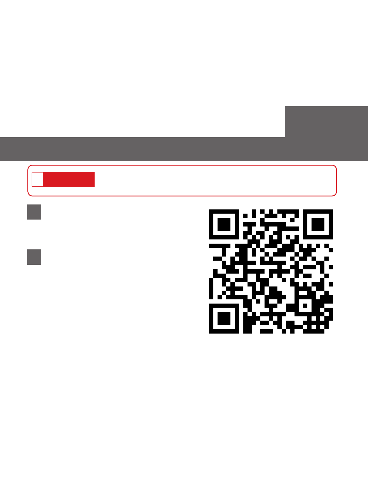
Online service order QR-Code:
Metrological control or repair work must be performed by
CNSystems or an authorized service partner!
Contact CNSystems via
Website: http://www.cnsystems.com/
support/service-order
Email: [email protected]
1
2
FAQs
38
Page 39
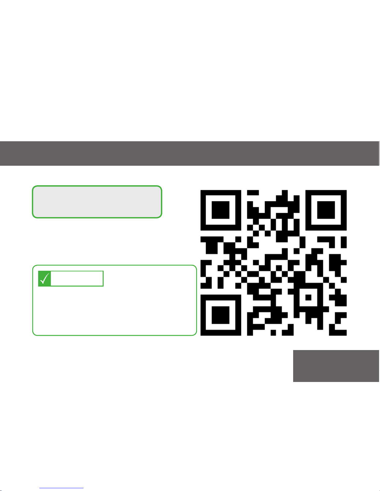
Service hotline QR-Code:
Service work is usually finished
within five working days.
Express-Service is possible on request!
NOTE
9. SERVICE HOTLINE
FAQs
39
SERVICE HOTLINE:
+43 316 723456 33
Page 40
10. WHERE TO GET ADDITIONAL INFORMATION
FAQs
CNAP® Monitor - Operators Manual
- Comes in hard copy with every CNAP
®
Monitor
- Available as PDF-file by CNSystems
Website - Applications
- http://www.cnsystems.com/applications
Downloads – Website
- http://www.cnsystems.com/support/downloads
Newsletter - Regular news about our products
- Register online:
http://www.cnsystems.com/news-events/newsletter
Website - Description of the technology
- http://www.cnsystems.com/innovation
CNSYSTEMS INFO LIBRARY
Still didn‘t find what
you are looking for?
Contact us directly!
http://www.cnsystems.com/
support/contact
40
Page 41
FAQs
11. HOW TO CONTACT CNSystems DIRECTLY
GENERAL REQUESTS
Contact form: http://www.cnsystems.com/support/contact
Email: [email protected]
Phone: +43 316 723456
Fax: +43 316 723456 2
REGISTER FOR OUR NEWSLETTER
Online: http://www.cnsystems.com/
news-events/newsletter
i
Newsletter registration
41
Page 42

42
Page 43

43
CNAP
®
Monitor 500 HD Quickguide
© CNSystems Medizintechnik AG, 2016
Version: 07/2016, V1.5.5 EN
Page 44
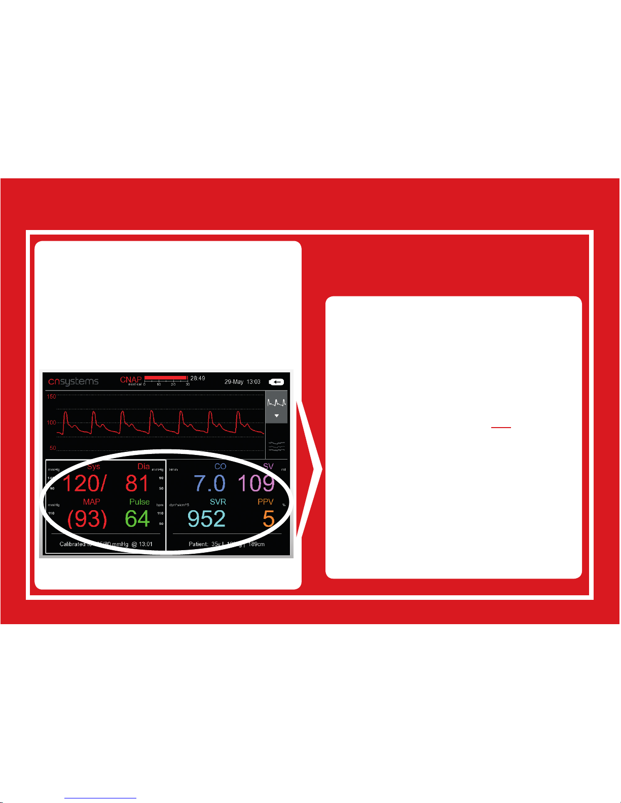
Backcover:
Currently using your
CNAP® Monitor
for blood pressure
monitoring only?
•
Full hemodynamics available
after 90 secs upon startup
•
Noninvasive HD for all low &
intermediate risk surgeries
•
as an addition to arterial line
•
Perfect match with all other
monitoring equipment
•
Improved accuracy through
calibration to manual CVP &
CO/CI
Upgrade to the full set of
hemodynamic parameters:
www.cnsystems.com
BP I PR I CO I SV I SVR I
PPV I SVV
with Software Upgrade V5.2:
 Loading...