

Page 1

Page 1
User Manual
for CN Boilers
Type
80 / 120
Machine no.
Date
CN Maskinfabrik A/S
Skovløkkevej 4, Tiset
6510 Gram, Denmark
Tel.: 74 82 19 19
Fax: 74 82 19 20 Version: April 2005
Page 2

Page 2
CONTENTS
Page 1. Front page
Page 2. Contents
Page 3. Function
Page 4. Dimensions
Page 5. Rating plate / Boiler with Cooling Spiral / Responsibilities / Safety
Page 5. Startup, Manual Stoking
Page 6. Installation and Assembly Guide
Page 7. Installation and Assembly Guide
Page 8. Installation and Assembly Guide
Page 9. Installation and Assembly Guide
Page 10. Maintenance, Cleaning and Frost Protection
Page 11. Technical Information. / Warranty Claims
Page 12. Check List, End User
Page 13. Check List, Supplier
Page 14. Check List, CN MASKINFABRIK A/S.
Page 15. Warranty Certificate, Customer Copy
Page16. 5 Year Warranty Certificate CN MASKINFABRIK A/S.
Page 17. Principle Diagram Overflow Valve / Cooling Spiral
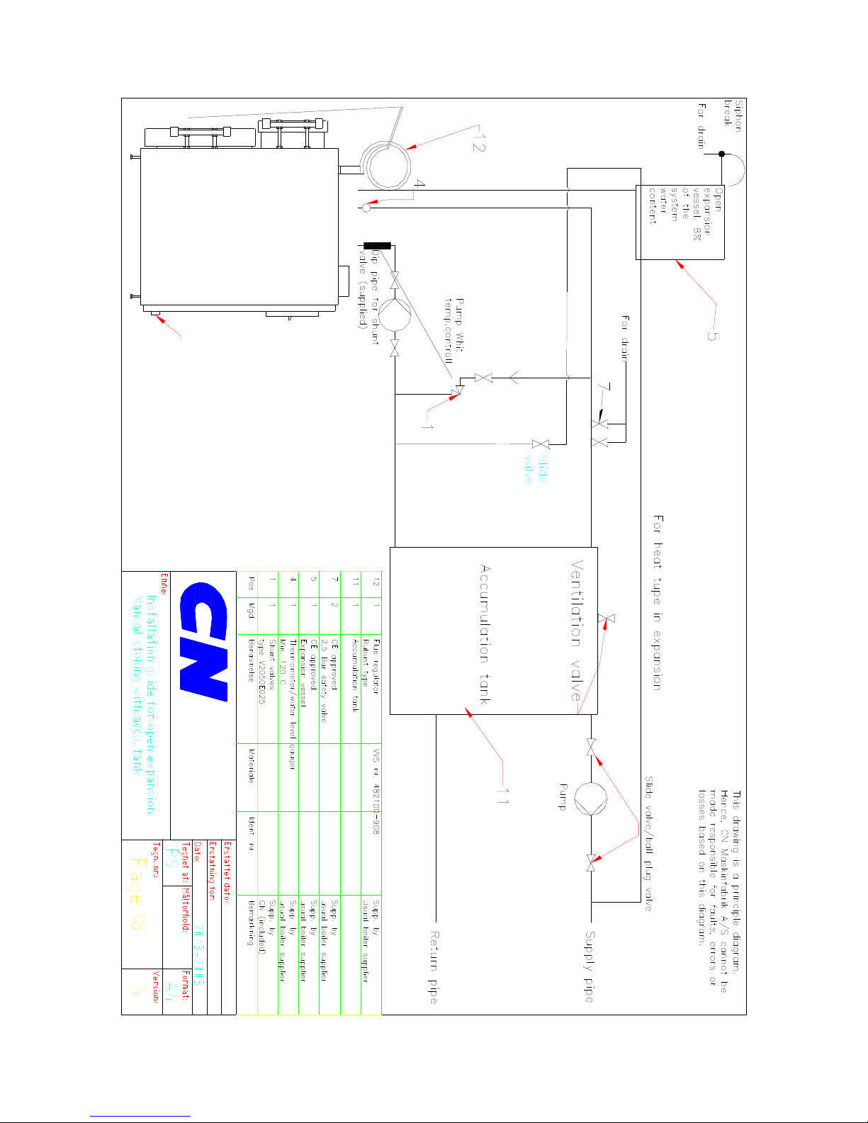
Page 18. Principle Diagram Open Expansion with Accumulation Tank.
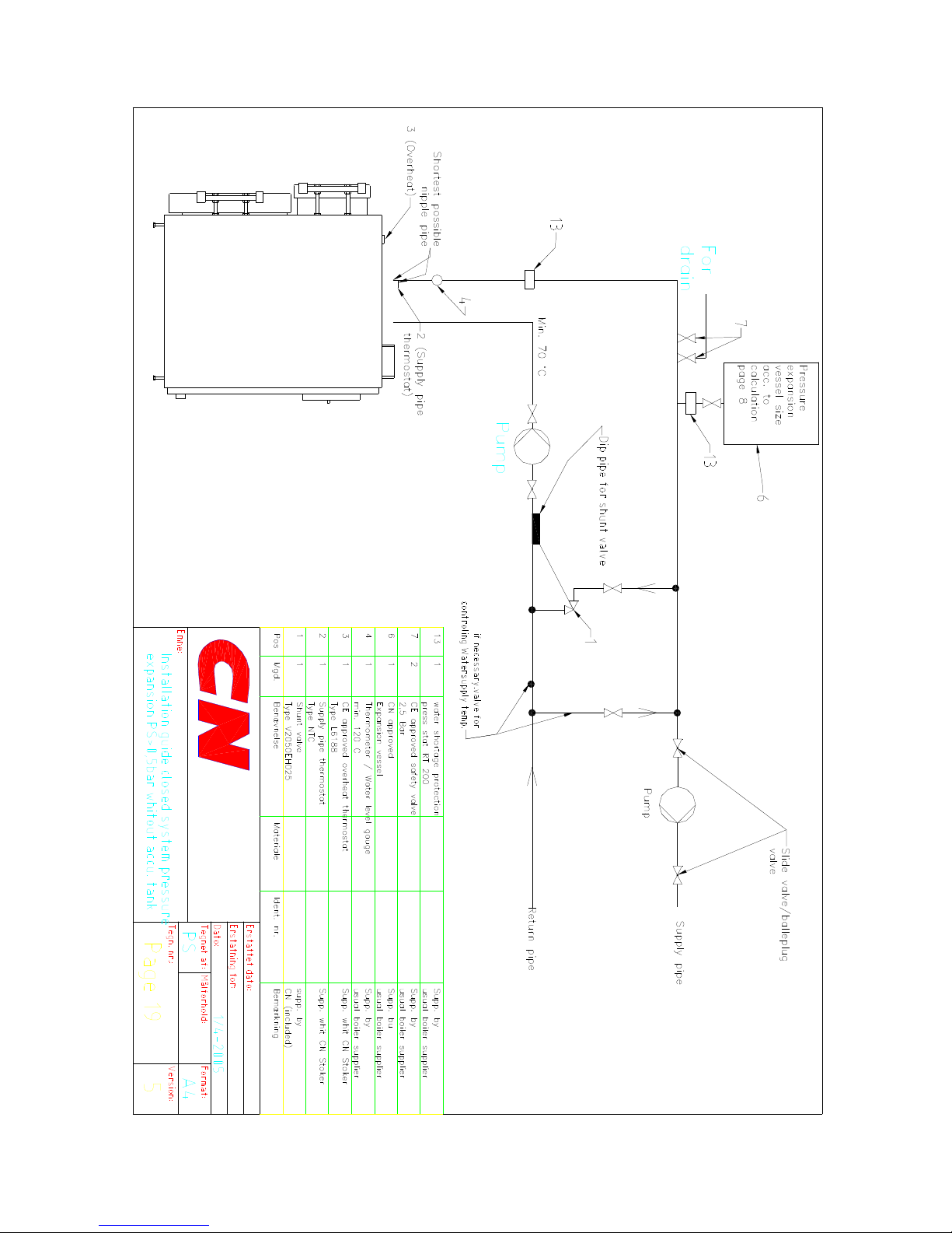
Page 19. Principle Diagram Pressure Expansion Without Accumulation Tank
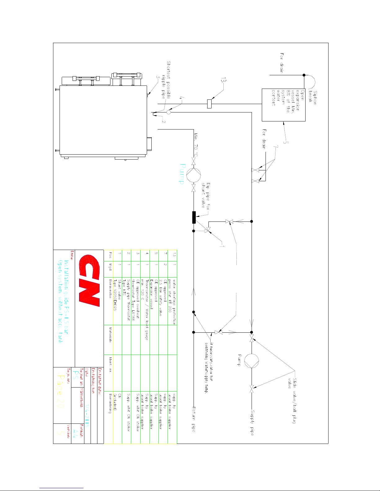
Page 20. Principle Diagram Open Expansion Without Accumulation Tank.
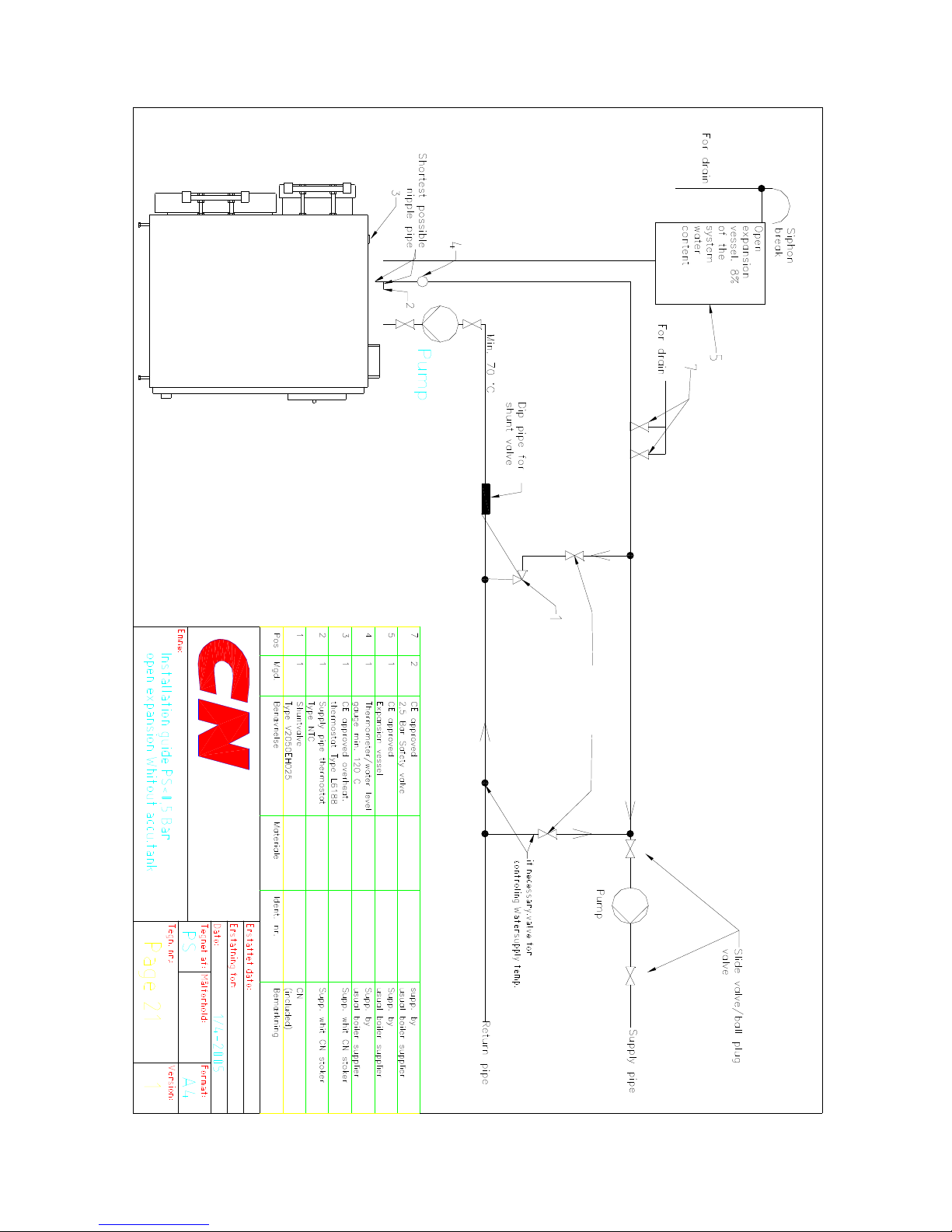
Page 21. Principle Diagram Open Expansion Without Accumulation Tank.
Accessories supplied with the boiler
1. Probe (dip pipe, valve, sensor)
2. Cleaning brush
3. Scraping tool
Page 3
Page 3
All CN boilers must be installed according to the Installation and Assembly
Guide below.
If the boiler is not installed in accordance with the installation instructions in the
user manual, it is the responsibility of the installation engineer to submit the
boiler unit to a construction test (module B1) or install the boiler unit in
accordance with a system of full quality assurance (module H) according to the
Pressure Equipment Directive 97/23/EEC. In both cases, an authorised body after
your own choice must be contacted.
Function
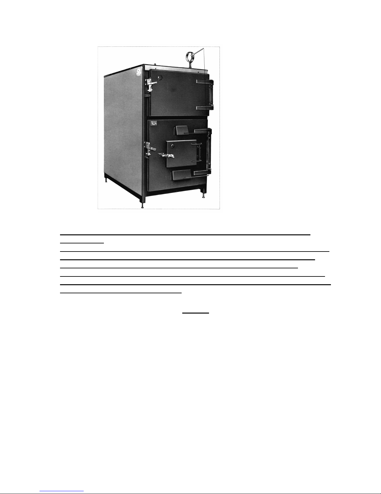
• The CN boiler is a triple-flue boiler constructed on the basis of many years’ experience and testing.
• The CN boiler is constructed with a large cylindrical fire chamber, specially developed for firing with
stoker, wood, wood chips, saw dust, peat, paper, coal or coke etc.
• The convection part of the CN boiler is placed on top of the fire box in the hottest part of the boiler,
which consists of many smoke gas sections surrounded by water.
• The construction and dimensions of the CN boiler thus create an efficient use of the smoke gas
before it reaches the smoke outlet
• The large doors of the CN boiler, which open both the fire chamber and the smoke ducts, make
cleaning the boiler very efficient and easy.
• Optimal, environmentally friendly and highly efficient burning of the wood requires correct ratio
between the combustion air and the smoke gasses from the fuel.
• The boiler is constructed with a large door to enable the burning of large objects.
• Acidifying substances such as plastic (PVC) must not be burned in the boiler, as they produce
hydrochloric acid fumes during combustion (HCL).
• Basifying substances must not be burned in the boiler, as they corrode the boiler during combustion.
•
It is important that the feeding of fuel is adjusted to allow the heat from the wood to be contained in
the heat reservoir at all times. The stoking should be adjusted so that the fuel has just been burned
when the heat reservoir reaches its maximum temperature.
• The boiler efficiency is larger when the boiler can deliver the heat without having to shut off the air
supply too much.
Page 4
Page 4
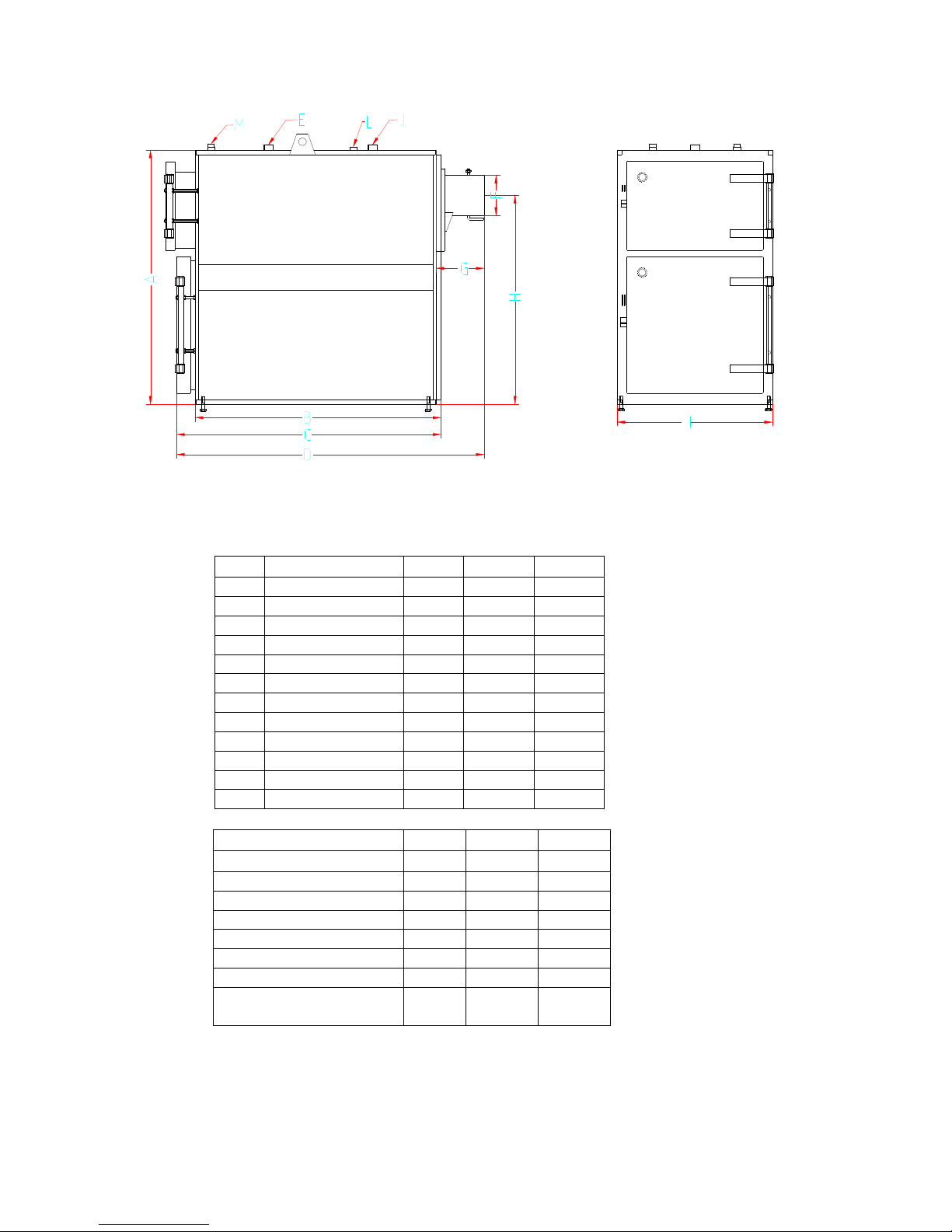
Key CN 80 CN 120
A mm 1700 1780
B mm 1540 1540
C mm 1800 1800
D mm 2130 2130
E Return pipe mm 2” 2”
F Smoke outlet mm 250 250
G mm 300 310
H mm 1400 1480
I mm 980 1180
J Supply / Return inches
2” 2”
L Expansion vessel inches
1” 1”
M Flue regulator inches
1” 1”
Yield wood
kW
65 100
Yield automatic stoking
kW
80 120
Heat surface m2 7.5 9.6
Volume fire chamber m2 0.75 1.07
Test pressure bar 4 4
Water content litre 490 560
Fire box diameter mm 815 970
Fire box depth mm 1450 1450
Smoke tube stub
diameter
mm 250 250
Page 5
Page 5
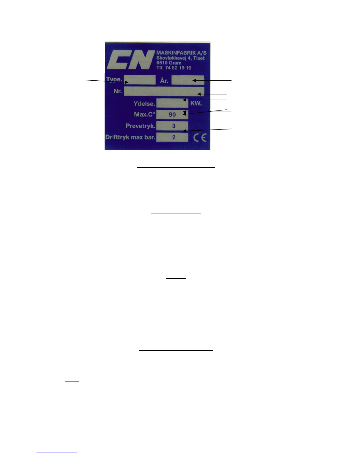
Boiler type Production year
Serial no.
Yield
Max. op. temperature
Test pressure
Oper. pressure
Boiler with cooling spiral
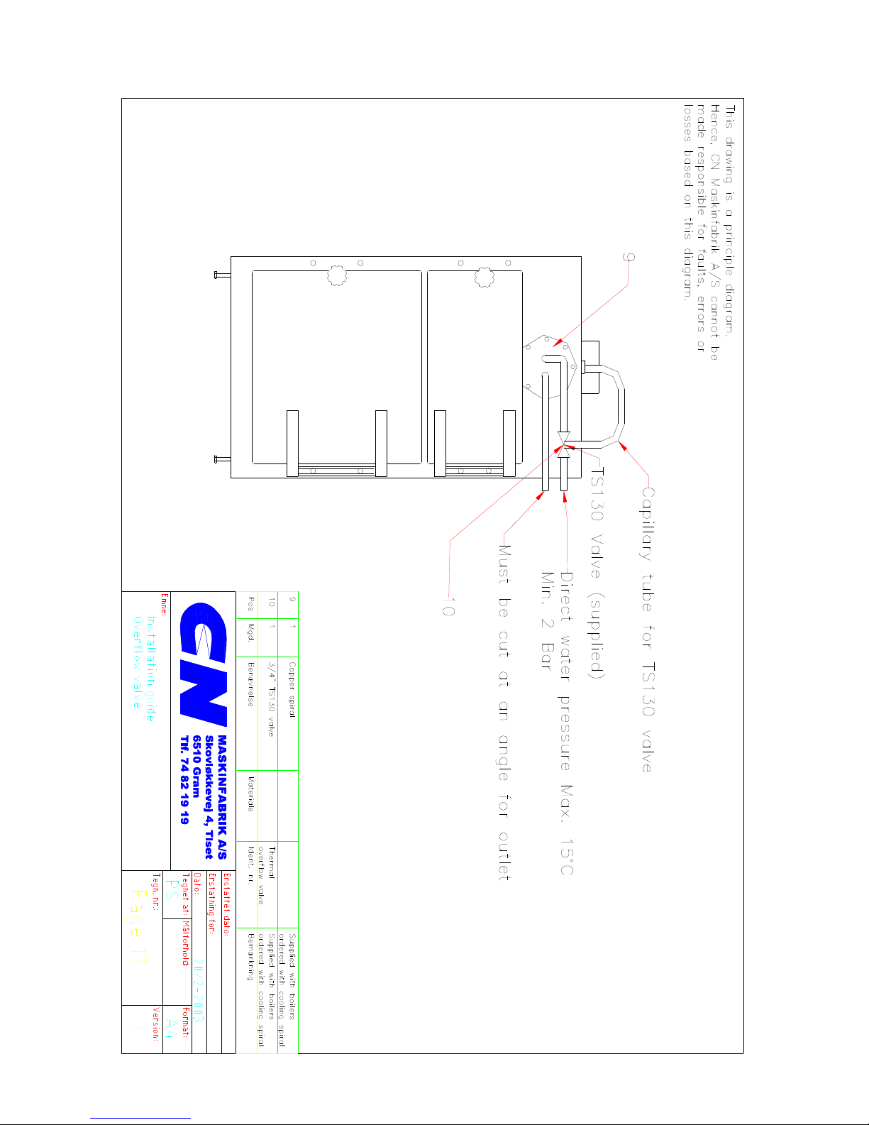
Boilers can be ordered with a cooling spiral, and this must be used for installation with pressure expansion,
and in open systems if the pressure in the boiler is above 0.5 bar over pressure.
The cooling spiral must only be used as a cooling spiral; it must not be used for heating up water for other
use. Therefore the cooling spiral must be left empty during operation. Water supply for cooling spiral
maximum 15 °C. Pressure for cooling spiral minimum 2 bar, maximum 10 bar.
Responsibilities
The user is responsible for the operation of the boiler and ensuring compliance with the operational
guidelines supplied by CN MASKINFABRIK A/S. Failure to comply with the guidelines may result in reduced
efficiency and increased negative effects on the environment, as the boiler will not achieve as clean emission
gasses as intended. Furthermore, incorrect operation can reduce the working life of the boiler.
Correct operation and installation are the best guarantees for a well-functioning boiler with a long life and a
good environment. The user needs to have the necessary willingness and correct attitude to burning wood,
as it does, after all, take a bit of work to ”yield the crops” of this environmentally friendly and financially
profitable type of heating
Safety
If any faults or failures are found, they must be repaired as soon as possible by a boiler engineer. Flue pipes,
ventilation ducts, air holes etc. must not be closed off or blocked. Flammable liquids or combustible
substances must not be placed in dangerous proximity to the boiler.
For systems with an operational pressure above 0.5 bar over pressure (closed system with pressure
expansion or open system where the height from the boiler to the highest water surface is more than 5
meter), the boiler must be equipped with a cooling spiral connected to a cold water supply.
Boilers equipped with a cooling spiral must not be used (should be switched off) if the water supply is out of
order, or the water supply to the boiler is shut off (e.g. on the main tap).
Startup, manual stoking
1. Fill the boiler with the required amount of combustible material.
2. Light the fuel from below.
3. Adjust the air supply hatches (only until the right air supply level is found) only during manual stoking
without stoker.
• Note. Be very careful when opening the door to the boiler during operation due to extreme heat
inside the boiler and smoke emission.
Stop: When the fuel material has been burned, the heat supply from the boiler stops.
Page 6

Page 6
Installation and Assembly Guide:
Norms and Directions
• It is the responsibility of the installation engineer that he has the necessary training and authorisation
to install the boiler. The size of the boiler should be based on the heating needs of the house rather
than the size of the fuel container.
The installation must fulfill the requirements described in the directions of the Health and Safety at
Work Act 1974, iincluding the following regulations: The Electricity at work Regs 1989, The Provision
and Use of Work Equipment Regs 1998, The Personal Protective Equipment Regs 1992,
The Fire Precautions (Workplace) (Amendments) Regs 1999, The construction Design and
Management Regs 1994. Current Institute of Electrical Engineers regulations. “The Pressure
Equipment Directive 97/23/EEC” and UK Building Regulations 2000 (as amended). See in particular
the following approved documents:
A: structure 2004 + amendments
B: fire safety 2000 edition + amendments
F: ventilation 2006 edition
J: combustion appliances and fuel storage systems 2002 edition
J: Guidance and supplementary information on the UK implementation of European standards for
chimneys and flues 2002 edition
L1A; L1B; L2A;L2B: Conservation of fuel and power 2006 edition.
M: Access to and use of buildings 2004 edition
P: Electrical Safety – Dwellings – 2006 edition
• If the boiler is used for burning straw, the installation must furthermore fulfill the requirements
described in the specific directions of The Health and Safety at Work Act 1974
• All smoke pipes must have an uphill gradient of minimum 1 %, and all joints must be tight. Never use
a smaller diameter smoke pipe as the boiler outlet pipe. Always use elbows with a bending and flap as
bent joints, as they provide the best flue. All smoke pipes must be insulated, also when the boiler
is used with stoker feeding.
• The combustion must not be carried out until the boiler is installed and fully connected.
• A probe must always be installed on the boiler, and the return pipe (pages 9/11) must always be
minimum 60° C during operation. See the assembly guide drawing.
• If the right physical conditions are present, the boiler may be installed on a base (approximately
400 mm high) to make the operation and removal of ashes easier.
Open or closed system
• CN boilers type 80 and type 120 are approved for installation as open or closed systems.
• When used as a closed system (with pressure expansion) and open system with a height above 5
meters, the boiler must be equipped with a cooling spiral and a thermal over temperature valve
(pages 7 & 8).
Safety valve requirements in closed systems
• With boilers > 60 kW every boiler must have at least 2 safety valves. The safety valves must be able
to, in combination at the chosen blow-off pressure, blow off at least 1.5 times the boiler heat yield in
the form of steam. They must, however, have a minimum internal diameter of 20 mm.
• The inlet and outlet hoses of the safety valves must be of sufficient dimensions for the capacity of the
safety valves not to be noticeably reduced. The inlet pipe must not contain blocking devices, pumps,
boiler mountings, restrictions or water sacks.
• All inlet and outlet hoses to and from safety valves must be run through pipes approved for 120 °C
and minimum 10 bar over pressure.
Page 7

Page 7
Safety hose open systems (open expansion)
• All the system boilers must have a connection to the atmosphere through a safety hose which cannot
be blocked.
• Safety hoses must depart from the top of the system boiler(s). They must run at an uphill gradient to
the open expansion vessel and from there run at a steady downhill gradient, at a suitable distance
from a drain and in such a way that the outlet of hot water does not result in a risk of injury. The outlet
point must be cut at an angle.
• At the highest point of the safety hose there must be an internal diameter of minimum 15 mm as a
siphon break.
• The vertical distance from the highest point of the system to the boiler must not exceed 10 meters.
• The total length of the safety hose must not exceed 20 meters.
• For boilers > 60 kW the safety hose must have a minimum internal diameter of 35.5 mm
• All pipes must be approved for 120 °C and minimum 10 bar over pressure.
For installation with operational pressure >0.5 bar and open expansion principle diagram pages
17 & 20 must be used
• If the operational pressure of the boiler exceeds 0.5 bar over pressure, the boiler unit (the installed
boiler including fittings and safety equipment) is covered by the Pressure Equipment Directive
97/23/EEC ”Installation of pressurised equipment”, which requires that the boiler unit must fulfil
certain essential safety requirements regarding the safety equipment of the boiler etc. The boiler
must be fitted with a cooling spiral
• Expansion vessel: The vessel must be installed in accordance with the directions of The Health and
Safety at Work Act 1974.
• The bottom of the expansion vessel should be installed only above pipes/radiator of the central
heating system and with an open expansion vessel. Block valves must under no circumstances be
placed between the boiler and the expansion vessel. There must under no circumstances be any
circulation in the expansion vessel.
The boiler must be installed with pos. nos. 1, 2, 3, 4, 5, 7, 9, 10, 13 (drawings pages 17 & 20)
Description Type / Requirements Draw. Pos no. Supplier
Shunt valve TA type TRV 300 1 CN (supplied)
Oper. thermostat BC components type NTC-2322 2 CN (supplied with stoker)
Overheat. thermostat Honeywell type L6188 3 CN (supplied with stoker)
Boiler thermometer 0-120 degrees 4 Installation engineer
Pressure gauge
(manometer)
0-3 maximum 5 bar, red mark at 2.5 bar 4 Installation engineer
Expansion vessel CE labeled, minimum 8 % of total system
water volume
5 Installation engineer
Safety valve
CE approved
2 pces., 2.5 bar, clearance minimum 20 mm
7
Installation engineer
Cooling spiral
CN80:
Wieland heat exchanger type WRK 13
9
CN (supplied)
Cooling spiral
CN120:
Wieland heat exchanger type WRK 13
9
Safety thermostat Honeywell type TS130, CE approved 10 CN
Water shortage protection RT 200 Pressostat 13 Installation engineer
Page 8

Page 8
For installation with operational pressure >0.5 bar and pressure expansion, principle diagram pages
17 & 19 must be used
• If the operational pressure of the vessel exceeds 0.5 bar over pressure, the boiler unit (the installed
boiler including fittings and safety equipment) is covered by the Pressure Equipment Directive
97/23/EEC ”Installation of pressurised equipment”, which requires that the boiler unit must fulfill
certain essential safety requirements regarding the safety equipment of the boiler etc. The boiler
must be fitted with a cooling spiral amongst other things
The boiler including fittings and safety equipment must be installed in accordance with the principle diagrams
on pages 17 and 19. The engineer must test the safety equipment in accordance with the section "Testing
the safety equipment" before the system is handed over to the user. The following fittings and safety
equipment etc. must, in accordance with the above-mentioned principle diagrams, be installed in the boiler
unit in order to be covered by the CN Maskinfabrik A/S Construction Test Certificate:
The boiler must be installed with pos. nos. 1, 2, 3, 4, 6, 7, 9, 10, 13 (drawings pages 17 & 19)
Description Type / Requirements Draw. Pos
nos.
Supplier
Shunt valve TA type TRV 300 1 CN (supplied)
Oper. thermostat BS components type NTC-2322 2 CN (supplied with stoker)
Overheating thermostat Honeywell type L6188 3 CN (supplied with stoker)
Boiler thermometer 0-120 degrees 4 Installation engineer
Pressure gauge
(manometer)
0-3 maximum 5 bar, red marks at 2.5 bar 4 Installation engineer
Pressure expansion
vessel
CE labeled minimum 4 % of total system
water volume (see table below)
6 Installation engineer
Safety valve
CE approved
2 pces., 2.5 bar, clearance minimum 20
mm
7
Installation engineer
Cooling spiral
CN 80:
CN120:
Wieland heat exchanger type WRK 13
Wieland heat exchanger type WRK 13
9
9
CN (supplied)
Safety thermostat Honeywell type TS130, CE approved 10 CN (supplied with stoker)
Water shortage protection RT 200 Pressostat 13 Installation engineer
NOTE:
• The system must have a membrane type expansion vessel with airbag. The expansion vessel must
have a durable and solidly fastened rating plate which clearly states Manufacturer, Volume in litres,
Test Pressure in bar and Initial Pressure in bar
• The expansion hose between the expansion vessel and the rest of the system must not be less than
25mm.
• Safety valve: The safety valve must be installed in accordance with the directions of The Health and
Safety at Work Act 1974.
• Expansion vessel: Expansion vessels: The vessel must be installed in accordance with the
directions of The Health and Safety at Work Act 1974.
•
Size of expansion vessel closed system:
Calculation of pressure expansion
Water expansion in % from 10 °C
Average temperature
°C
%
60 1.7
70 2.3
80 3.0
90 3.6
100 4,4
Page 9

Page 9
110 5,2
120 6,0
Expansion vessel efficiency Example of calculation (new systems)
in % after initial and operational pressure
Oper. pressure bar
In.
pres.
1.0 1.5 2.0 2.5
0.5
25 40 50 57
1.0
20 33 42
1.5
16 28
2.0
14
For boilers with open expansion and operational pressure < 0.5 bar, the principle diagram pages 18 &
21 must be used
If the operational pressure of the boiler is below 0.5 bar, the boiler must be installed in accordance with
the directions of The Health and Safety at Work Act 1974 about combustion hot water systems. Cooling
spiral is not required. The bottom of the expansion vessel should be installed above the highest
pipe/radiator of the central heating system and with an open expansion vessel. Block valves must under
no circumstances be placed between the boiler and the expansion vessel. There must under no
circumstances be any circulation in the expansion vessel.
Size of expansion vessel open system:
The expansion vessel must be at least 8 % of water content (boiler + reservoirs + pipes and radiators)
acc. to Btv32.
Boilers exclusively used for manual stoking must be installed with following pos. nos. 1, 4, 5, 11, 12
(draw. page 18)
Boilers used with stoker pos. nos. 1, 2, 3, 4, 5 (draw. page 21)
Description Type / Requirements Draw. Pos no. Supplier
Expansion vessel CE labeled, minimum 8 % of total system
water volume
5 Installation engineer
Oper. thermostat BS components type 2322 2 CN (supplied with stoker)
Overheat. thermostat Honeywell type L6188 3 CN (supplied with stoker)
Boiler thermometer 0-120 C° degrees 4 Installation engineer
Pressure gauge
(manometer)
0-3 maximum 5 bar, red mark at 2.5 bar 4 Installation engineer
Accumulation tank
Type approved in acc. with ”Declaration on
Installation of Pressurised Equipment”
11 Installation engineer
Shunt valve TA type TRV 300 1 CN (supplied)
Flue regulator 1” Robust 12 Installation engineer
Testing the safety equipment
.
The engineer must test the safety equipment before the unit is handed over to the user.
• The engineer must check that the operation thermostat is working.
• The engineer must also check the overheating protection.
This is done by removing the overheating thermostat from the dip pipe and placing it in boiling water.
The thermostat should now cut out and the system stop. Reset the thermostat once the temperature
has fallen, and place it back in the dip pipe.
• The engineer must also check that the safety valves open at max 2.5 bar.
• The engineer must test the operation of the thermal valve for the cooling spiral. The valve should
open at a sensor temperature of maximum 95 °C. Remove the sensor from the dip pipe and place it
in boiling water. Check that water now flows through the cooling spiral. Replace the sensor in the dip
pipe.
Maximum system temperature °C 90 °C
Water content heating system
Boiler (type 25) 180 L.
Installation 350 L.
530 L.
Water exp. (530x3,6/100) 19.08
Expansion vessel efficiency 57 %
Size expansion vessel
(19.08x100/57)=33.47=
34 L.
Page 10

Page 10
•
When installing Water shortage protection Type RT 200 Pressostat, the installation engineer must
adjust the pressostat so that it stops the system, when the operational pressure is below 0.5 bar over
pressure. Furthermore, the installation engineer must test that the pressostat physically stops the
system when the operational pressure < 0.5. This is done by filling the system to more than 0.5 bar
over pressure, starting the system and shut off the water supply until the system stops; this should
happen at 0.5 bar over pressure.
Maintenance and cleaning:
•
The closing mechanisms of the door and cleaning hatch are adjusted from the factory but must be
inspected for correct sealing after a month of use, when the gasket has ”settled”.
• If any irregularities are found in the safety valve(s), expansion vessel or automatics of the unit, the
owner/user must immediately have the equipment in question inspected and repaired by an
authorised engineer. The owner/user must ensure that any installed safety valves are not blocked by
scale etc. It is the responsibility of the owner/user that the boiler and any equipment is cleaned and
maintained according to:
•
Normal practice,
• The boiler flue system is cleaned by opening the top hatch of the boiler. The many flue pipes placed
at the top of the boiler should be cleaned every 3 days with the round cleaning brush/cleaning tool
supplied with the boiler. Push the brush all the way through; take care not to damage the bottom tile
in the smoke box. Pull the brush / cleaning tool back out; repeat several times for each pipe. After
cleaning, empty the smoke box at the back of the boiler. The boiler must always be switched off
during cleaning. Clean smoke pipes and smoke box result in more economical operation.
• The boiler combustion chamber should be cleaned every 24 hours (of use).
•
If the boiler is switched off for a long period (approximately 1 week), the boiler and flue pipes should
be cleaned thoroughly, as the residue combined with damp results in corrosion
.
• The pump(s) must be switched off whilst the system is filled up with water
• NOTE: Do not fill up an overheated boiler with water.
• Installation with pressure expansion: water filling until 1.5-2.0 bar.
• Installation with open expansion: water filling until the water runs out of the expansion vessel
overflow.
• Testing the safety valves: It is the responsibility of the user that the installed safety valves are
tested twice annually. This is done by pressing or turning the valve test device. By doing this you are
able to see and hear a bit of water being released and thereby confirm that the valve is operational.
Damages caused by a blocked safety valve are not covered by the warranty issued by CN
MASKINFABRIK A/S.
• Safety valves are installed in connection with the central heating unit (2.5 bar) and possibly in
connection with the hot water circuit (6 bar or 10 bar). Please ask your installation engineer if in doubt
about the location of the valves.
• After 300 hours’ operation, nuts and bolts must be tightened and doors adjusted!
Replacing the glass string in doors
• Open the door. Remove the old gasket, if necessary with a chisel or a screw driver. Clean the gasket
groove. Push the new gasket into the groove. Put the last end in place when this is about half done,
and then the rest. Bang the string lightly with a hammer if necessary.
Frost protection:
• During normal operation above freezing point there is no need for frost protection.
• The central heating unit can be protected with anti-freeze solution. Remember, however, that the hot
water container, if relevant, is not protected against frost.
• When stopping the unit at an ambient temperature below zero, the boiler must be emptied of water.
This is done by running a hose from the bottom tap of the boiler to a drain in the floor and opening
the tap.
Page 11

Page 11
Technical information CN80 / 120 boiler installed with 80/120 kW CN Stoker
• Smoke gas temperature 80 / 120 boiler at nominal yield with wood pellets: 142 /
134 °C
• Smoke gas temperature 80 / 120 boiler at 20 % yield with wood pellets: 78 / 83 °C
• Smoke gas mass flow 80 / 120 boiler at nominal yield: 140 / 229 kg/h
• Smoke gas mass flow 80 / 120 boiler at partial load 20 % yield: 54.8 / 88 kg/h
• Nominal yield 80 / 120 boiler in nearest whole kW with wood pellets: 82 / 117 kW
• Yield range 80 / 120 boiler 20 % -100 %:16.7-82 / 32-117kW
• Required flue 80 / 120 boiler 14 Pa
• Chimney must have an internal diameter of minimum 250mm and be of an
approved type.
• The boiler thermostat setting range is 55-85 °C
• Water content in 80 / 120 boiler: 490 / 560 L.
• Boiler classification: 3
• Set point for boiler thermostat: 65 °C
Warranty Claims
CN MASKINFABRIK A/S provides a 24 month warranty for the stoker unit following the
date of this user manual for the first user.
The warranty includes materials and manufacturing faults, but not wear on parts, damages
caused by failure to maintain the unit, incorrect use or overloading.
Claims will be compensated based on the price of the spare parts or repair, if this is
cheaper. Labour wages according to an hourly labour rate for normal working hours as
specified by CN MASKINFABRIK A/S.
The warranty does not cover transport, freight, consequential damages and operational
losses.
This warranty is not valid until CN MASKINFABRIK A/S has received the check list
on p. 14.
Page 12

Page 12
CHECK LIST
User manual received
I have received instructions in the use of the boiler,
including what fuel material may be fed to the boiler.
I have received instructions in the maintenance of the boiler
Boiler type :
Serial number:
Year :
I hereby declare that I have understood the received material.
Name : ____________________________________
Address : ____________________________________
Town and post code: ____________________________________
____________________________________
Signature
For:
End user
Page 13

Page 13
CHECK LIST
User manual received
I have received instructions in the use of the boiler,
including what fuel material may be fed to the boiler.
I have received instructions in the maintenance of the boiler
Boiler type :
Serial number:
Year :
I hereby declare that I have understood the received material.
Name: ____________________________________
Address: ____________________________________
Town and post code: ____________________________________
____________________________________
Signature
Please return to:
Supplier
Page 14

Page 14
CHECK LIST
User manual received
I have received instructions in the use of the boiler,
including what fuel material may be fed to the boiler.
I have received instructions in the maintenance of the boiler
Installation carried out by :_______________________________________________
__________________________________________
Signature
Please check below
The installation was carried out in accordance with the Installation and Assembly Guide in the user
manual and is thus covered by the CN MASKINFABRIK A/S Construction Test
Certificate______________
The installation engineer has subjected the boiler unit to a construction test (module B1) or
installed the boiler unit in accordance with a full quality assurance system (module H) in
accordance with the Pressure Equipment Directive 97/23/EEC
. _____________________
Boiler type :
Serial number:
Year :
I hereby declare that I have understood the received material.
Name: ____________________________________
Address: ____________________________________
Town and post code:__________________________________
____________________________________
Signature
Please return to: CN MASKINFABRIK A/S,
Skovløkkevej 4,
Tiset
6510 Gram,
Denmark
This warranty only comes into force when CN MASKINFABRIK A/S has received this page signed
Page 15

Page 15
by the customer and the installation engineer
Warranty Certificate
(Customer copy)
CN MASKINFABRIK A/S provides a 5 year warranty for penetrating corrosion of
the boiler if the following points are adhered to.
1.
The warranty certificate on page 14 is signed, returned and complied with
2.
All points of the user manual are complied with
3.
The unit is serviced minimum once a year by CN MASKINFABRIK A/S or a
company approved by CN MASKINFABRIK A/S.
4.
The check list on page 12 is returned to CN MASKINFABRIK A/S
5.
The boiler must a no time have been used for burning grain.
6.
The boiler must not be exposed to insufficient maintenance, incorrect use or
overloading.
7.
CN MASKINFABRIK A/S will repair any claims or approve the repair before it
is carried out according to the choice of CN.
The service includes the following:
• Gaskets inspected and checked.
• Doors inspected, tightened and adjusted.
• Boiler cleaned and inspected
• Installation inspected.
• Smoke pipe inspected and checked
• Any fire resistant materials inspected and checked
• Cleaning tools inspected and checked.
• The boiler must be cleaned prior to service
Serial number: ___________ Date:_______________
Signature: _______________________________
Page 16

Page 16
Warranty Certificate
CN MASKINFABRIK A/S provides a 5 year warranty for penetrating corrosion of
the boiler if the following points are adhered to.
1.
The warranty certificate on page 14 is signed, returned and complied with
2.
All points of the user manual are complied with
3.
The unit is serviced minimum once a year by CN MASKINFABRIK A/S or a
company approved by CN MASKINFABRIK A/S.
4.
The check list on page 12 is returned to CN MASKINFABRIK A/S
5.
The boiler must a no time have been used for burning grain.
6.
The boiler must not be exposed to insufficient maintenance, incorrect use or
overloading.
7.
CN MASKINFABRIK A/S will repair any claims or approve the repair before it
is carried out according to the choice of CN.
The service includes the following:
• Gaskets inspected and checked.
• Doors inspected, tightened and adjusted.
• Boiler cleaned and inspected
• Installation inspected.
• Smoke pipe inspected and checked
• Any fire resistant materials inspected and checked
• Cleaning tools inspected and checked.
• The boiler must be cleaned prior to service
Please return this page to: CN MASKINFABRIK A/S
Skovløkkevej 4 Tiset
6510 Gram, Denmark
Name :________________________________
Address :________________________________
Town :___________ Post code:__________________
Tel.: :________________________________
Serial number: ___________ Date:_______________
Signature: __________________________________
Page 17
Page 17
Page 18
Page 18
MASKINFABRIK A/S
Skovløkkevej 4, Tiset
6510 Gram
Tlf. 74 82 19 19
MASKINFABRIK A/S
Skovløkkevej 4, Tiset
6510 Gram
Tlf. 74 82 19 19
Check
valve
Draining
Page 19
Page 19
MASKINFABRIK A/S
Skovløkkevej 4, Tiset
6510 Gram
Tlf. 74 82 19 19
This drawing is a principle diagram.
Hence, CN Maskinfabrik A/S cannot be
made responsible for faults, errors
or losses based on this diagram.
Check
valve
Page 20
Page 20
MASKINFABRIK A/S
Skovløkkevej 4, Tiset
6510 Gram
Tlf. 74 82 19 19
This drawing is a principle diagram.
Hence, CN Maskinfabrik A/S cannot be
made responsible for faults, errors
or losses based on this diagram.
Check valve
Page 21
Page 21
MASKINFABRIK A/S
Skovløkkevej 4, Tiset
6510 Gram
Tlf. 74 82 19 19
This drawing is a principle diagram.
Hence, CN Maskinfabrik A/S cannot be
made responsible for faults, errors
or losses based on this diagram.
Check valve
 Loading...