

Page 1
Operation Manual
CX4.40, CX4.50, CX4.100
CX4.150, CX4.180, CX4.240
Professional Class-D Four Channel Amplifier
Please follow the instructions in this manual to obtain the optimum results from this unit.
We also recommend that you keep this manual handy for future reference.
Professional Sound System
Page 2

1. SAFETY PRECAUTIONS ............................................................................ . 1
2. PRODUCT INTRODUCTION ................... .................... .................................. 3
3.
FEATURES..................................................................................................3
4. EFFI CIENCY................................................................................................4
5. POWER SUPPLY...................... ......................... ......................... ................. 4
6. SUITABLE APPLICATION.............................. ......................... ..................... 4
7. NOMENCLATURE AND FUNCTIONS
7.1 Front Panel .................................... .............................................. .... ...5
7 .2 Rear
Pa nel
.............. .............................................................................5
8. OPERATION INSTRUCTIONS.......................................................................6
9. TROUBLE SHOOTING ..................................................................................6
10. APPLICAT IO NS........ ...................................................................................7
11. BLOCK DIAGRAM............................................. ............. ............ ... ..............8
12.SPECIFICATIONS.................................................................. ..................... 9
13.SERVICE & WARRANTY.................................... ......................... .................10
Page 3
1.
SAFET
Y PRECAUTIONS
1 / 12
Be sure to read the instructions in this section carefully before use.
Make sure to observe the instructions in this manual as the conventions of safety symbols and messages
regarded as very important precautions are included.
We also recommend you keep this instruction manual handy for future reference.
Safety Symbol and Message
Conventions
Safety symbols and messages described below are used in this manual to prevent bodil y injury and property
damage which could result from mishandling. Before operating your product, read this manual first and
understand the safety symbols and messages so you are thoroughly aware of the potential safety
Indicates a potentially hazardous situation which, if mishandled, could
result in death or serious personal injury.
Indicates a potentially hazardous situation which, if mishandled, could
result in moderate or minor personal injury, and/or property damage.
When
Installing
the Unit When
Installing
the
Unit
Do not expose the unit to rain or an
environment
where it may be splashed by water or other
liquids,
as doing so may result in fire or electric shock.
Use the unit only with the voltage specified on
the unit. Using a voltage higher than that
which is specified may result in fire or electric
shock.
Do not cut the link otherwise damage nor modify
the
power supply cord. In addition, avoid using
the
power cord in close proximity to heaters, and
never
place heavy objects - including the unit
itself -
on
the power cord, as doing so may result
in fire
or
electric shock.
Be sure to replace the unit's terminal cover after
connection completion. Because high voltage
is
applied to the speaker terminals, never touch
these
terminals to avoid electric shock.
Be sure to ground to the safety ground (earth)
terminal to avoid electric shock. Never ground
to a gas pipe as a catastrophic disaster may result.
Avoid installing or mounting the unit in unstable
locations, such as on a rickety table or a slanted
surface. Doing so may result in the unit falling
down, causing personal injury and / or
property
damage.
Should the following irregularity be found during
use, immediately switch off the power,
disconnect
the power supply plug from the AC outlet and contact
your nearest dealer. Make no further attempt
to
operate the unit in this condition as this may
cause
fire or electric shock.
If you detect smoke or a strange smell coming
from the unit.
If water or any metallic object gets into the unit
If the unit falls, or the unit case breaks
If the power supply cord is damaged (exposure
of the core, disconnection, etc.)
If it is malfunctioning (no tone sounds.)
To prevent a fire or electric shock, never open nor
remove the unit case as there are high voltage
components inside the unit. Refer all servicing
to your nearest dealer.
Do not place cups, bowls, or other containers of
liquid or metallic objects on top of the unit. If they
accidentally spill into the unit, this may cause a
fire or electric shock.
Do not insert nor drop metallic objects or flammable
materials in the ventilation slots of the unit's cover,
as this may result in fire or electric shock.
Page 4

SAFET
Y PRECAUTIONS
2 / 12
When Installing the Unit When Installing the Unit
Never plug in nor remove the power supply plug
with wet hands, as doing so may cause electric
shock.
When unplugging the power supply cord, be sure
to grasp the power supply plug; never pull on the
cord itself. Operating the unit with a damaged
power supply cord may cause a fire or electric
shock.
When moving the unit, be sure to remove its power
supply cord from the wall outlet. Moving the unit
with the power cord connected to the outlet may
cause damage to the power cord, resulting in fire or
electric shock. When removing the power cord, be
sure to hold its plug to pull.
Do not place heavy objects on the unit as this may
cause it to fall or break which may result in personal
injury and/or property damage. In addition, the object
itself may fall off and cause injury and/or damage.
Make sure that the volume c ontrol is set to
minimum
position before power is switched on.
Loud noise produced at high volume when power
is switched on can impair hearing.
Do not operate the unit for an extended period of
time with the sound distorting.
This
is an
indication
of a malfunction, which in turn can cause heat to
generate and result in a fire.
Do not block the ventilation slots in the unit's cover.
Contact your dealer as to the cleaning. If
Doing so may cause heat to build up inside the unit
and result in fire.
Avoid installing the unit in humid or dusty locations,
in locations exposed to the direct sunlight, near the
heaters, or in locations generating sooty smoke or
steam as doing otherwise may result in fire or
electric shock.
Due to product upgrades, while some of the
features and specification in the user manual
does not match the actual functions, sorry for
any inconvenience and thanks for your kind
understanding!
dust is allowed to accumulate in the unit over a
long period of time, a fire or damage to the unit
may result.
If dust accumulates on the power supply plug or in
the wall AC outlet, a fire may result. Clean it
peri
odically. In addition, insert the plug in the wall
outlet
securely.
Switch off the power, and unplug the power supply
plug from the AC outlet for safety purposes when
cleaning or leaving the unit unused for 10 days or
more. Doing otherwise may cause a fire or electric
shock.
An all-pole mains switch with a contact separation of at least 3 mm in each pole shall be incorporated in
the electrical installation of the building.
Page 5

2.
PRODUC
T INTRODUCTION
3 / 12
The Class-D range four channel power am plifiers are our la tes t digit al professional power amplif ier,
which is the ne w miles tone in s witch p owe r t ech nology amplifi ers . It is of light and 1R U height but
ca n prov ide you with unpr ece den ted st ron g po wer. T he high so und quality wil l be a new m arker of
pr ofessiona l audi o m arket. The class-D range four channel po wer am plifiers of fer six different power
ra tin gs from 4x2 50W (8 Ohm ) to 4x 130 0W(8 Ohm ) , and this is onl y p rovide d by one rack unit, the
machi ne' s bi ggest net wei ght is onl y 8 k g.
The professional class-D four channel power amplifier u sin g classic PWM circu it a nd per fect
pr otecti on cir cui t, w ith high stability an d appl icabil ity, timb re l arge dyn amic ran ge, sm all vol ume ,
light weight, hig h eff ici enc y, smal l di stortion, high power, etc.
Th e po wer am plifier adop ts the b est power sup ply des ign with circ uit sta bil ity, high efficiency, low
ha rmo nic . In te rms of dig ita l power am plific ati on, D class am plifier is also exc ellent . Afte r years of
ex per ime nt, we succes sfu lly developed a new typ e of circuit topology, after the new signal m o dul ati on
mode, the music sig nal be com es b etter digital si gnals. The em ergenc e of this new mod ula tio n method,
of fers gu ara nte e for som e tiny sig nal sa mpling, com ple te the form. In a ddi tion, we also incre ase d th e
fixed switch ing fr equ enc y of th e po wer, p rec ise controlled of the dead zone tim e, lower p ower ampl ifi er
distorti on d egree, make t he sou nd quality equ al o r ex cee d th e trad iti ona l analog power am plifie r.
3.
FEATURES
1. Advanced switch ing po wer sup ply tec hnology, can pro vide high qualit y soun d, c ompact vol ume.
2. Low noise and hi gh q ual ity spe ed controlled fa n, using industr y best cooling fan o f minimize the n ois e.
3. Wit h buil t-i n soft start c irc uit fo r low AC surg e current, ca n re pla ce the p owe r sequencer.
4. The standard Combined XLR connector and 6. 3 mm Ph one jack one- piece par allel s ock et.
5. Built- in C lipping lim iting d evi ce.
6. Clipping lim iti ng d evice with compr ehe nsive status indic ators on the front panel, inc luding the power
lamp, fiv e peri od of sign al, pressu re lim it l igh t, pro tec tio n lamp and so on.
7. Ful l prot ect ion circuits, power am p lif ier co nsists of overload protec tion, short c irc uit protection,
temperature pro tec tio n, power lim itation protection , signal pressur e limit pr ote ction, dc protec tio n
cu rre nt, peak limiting pr otecti on, etc. Power prot ection includes under volta ge pro tection, o ver voltag e
pr otecti on, ove r curr ent pre ssure lim it prot ection, ove r-c urrent shutdo wn pro tec tion, o ver temperature
pr otecti on, etc.
8. 19” rack mou nt des ign in 1 RU height.
Page 6

4 . EFF I C I E NC
Y
4 / 12
Compared wit h the t rad itional audio power am plifie r, D serie s powe r am plifie r show more excel lent
pe rforma nce , while significantly reduce heat, offer mor e st ron g power to th e speak ers . High conver sion
ef fic iency which ca n make the s ize of th e po wer ampl ifier, weight and po wer cons ump tio n great ly reduced.
Ou tpu t ef fic iency rea ches up to 95%.
Th e bi gge st difference betw een class-D power amp lif ier and the tr adi tional powe r am p lifier is the highest
ef fic iency, t he traditional powe r am plifier is full associated with the ou tpu t, and dig ita l power am plifier is
almos t not affecte d by o utp ut constraints, bec aus e of th e infl uence o f musi c o n av era ge power d ens ity,
even the volume of the tra dit ion al p ower amplifier a nd digital power am plifie r s et to be the same, we will
find tha t th e traditiona l po wer am plifier pr odu ce mor e than 10 times heat than the digital power a mplifier.
5 . P OW E R
SU P P L Y
The Professional class-D four channel power am p lifier with high effic iency, goo d stability switch p ower
su ppl y, lig ht weight, hi gh eff icienc y and power reser ves , wide input voltage ra nge , power ef fic iency
over 9 5%.
6 .
SU I T ABL E AP P L IC A TI O N
1. Tour system or fixed sound installation
2. Sound r einforcem ent system
3. Live perf orm anc e sound re inf orc e
4. Confer enc e system s ound reinforce
5. Backgr ound music system
6. To dr ive high-power and low-fr equ enc y sp eak ers
Page 7
7. NO M E N C
L A
TUR
E AND FU N C T I ON
S
5 / 12
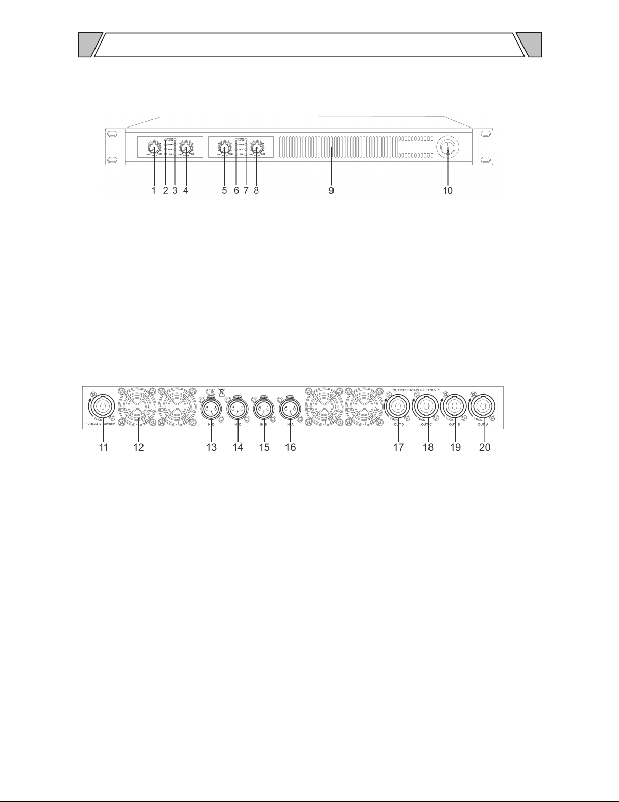
Fr ont Pan el
1. CH- A volum e control
2. CH-A out put level m ete r
3. C H-B output level meter
4. CH- B volume c ontrol
5. CH- C volum e contr ol
6. CH-C output le vel mete r
7. C H-D output level meter
8. CH- D volume c ontrol
9. Air inlet
10. Power switc h
Re ar Pane l
11. AC Power s ock et
12. S pee d c ontrol cooling fa n
13. CH- D signal XLR in put
14. C H-C si gna l X LR input
15. C H-B signal XLR input
16. CH- A signal X LR input
17. CH -D spe ake r outp ut
18. C H-C sp eak er out put
19. C H-B sp eaker output
20. C H-A sp eaker output
Page 8
8. O P E R A TI O
N
IN S T R UCT I O N
S
6 / 12
1. Power on
1. 1 According to introduction, mak e the setting and wir ing co rrectly.
1. 2 Ch eck short circ uit be twe en inpu t cabl e an d output cable.
1. 3 Ch eck wheth er the loc al p owe r grid are in conf orm ity wit h th is manu al.
1. 4 Make sure th e powe r is off , turn the vol ume to the minim um.
1. 5 Co nne ct the power sup ply, tur n on th e au dio source, po wer on this digital am p lif ier;
Adjus t the volume knob clock wis e to suita ble location.
1. 6 Turn on the eff ect device s an d the p rof ess ional amplif ier and make s ure th e ab ove
eq uipments w ork properly.
2. Power off
2. 1 Adjust the vol ume kno b coun terclockwise to the minimu m.
2. 2 Turn off the switch, set to OFF p osi tio n.
2. 3 Turn off the prof ess ional dig ita l am p lifier, set to OFF. T hen tur n off the effect equ ipm ents,
au dio sources.
9. T R O U BLE
SHO O T I N G
Fa ult phe nom eno n Th e cause of the pr oblem
Th ere is no s oun d outp ut
when the line co nne ction is g ood
1. No e lectricit y or plug con tac t undes ira ble
2.The fus e was b urn ou t
3.The vol ume is not open
4. No i npu t sign al
No rma l st art up, th e alarm trigg ere d
1. Loa d shor t circuit or damaged
2. Power sup ply voltage is no t stable, too high or
to o low
3. Ove rlo ad
In the normal us e of all of a sudden
no sou nd out put
1. Temp era tur e is to o hi gh, the m a chi ne in
temperature pro tec tio n
2. Loo se cable c onn ect ion
Page 9
7 / 12
10.
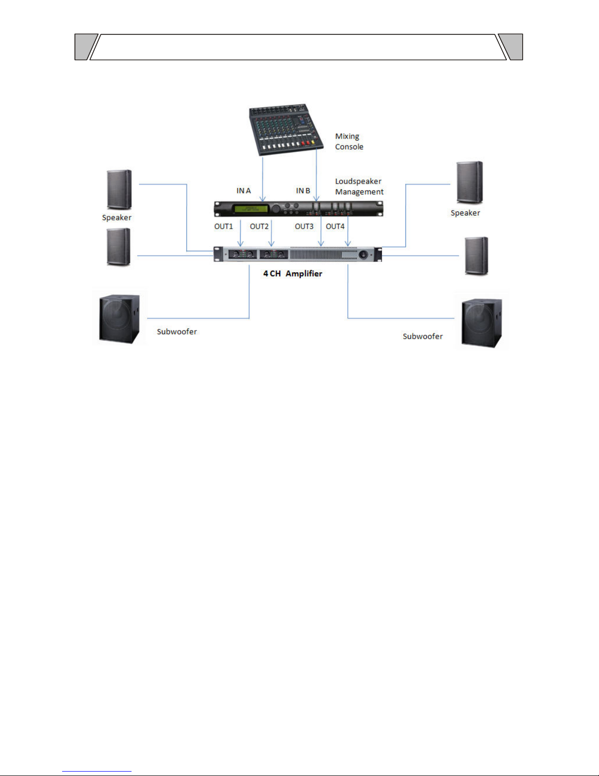
CONNECTION DIAGRAM
Page 10
8 / 12
11. BLOCK
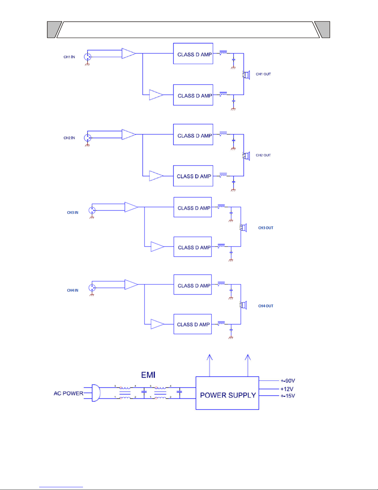
DIAGRAM
Page 11
9 / 12
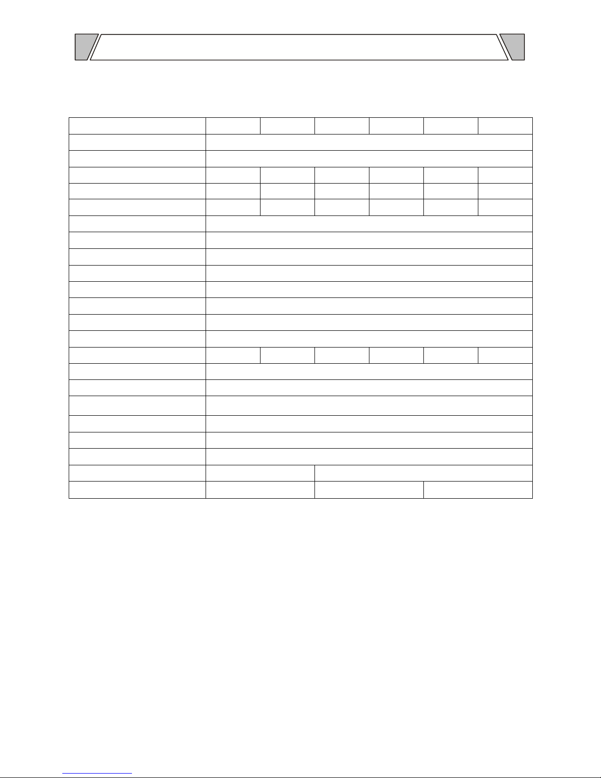
Model CX4.40 CX4.50 CX4.100 CX4.150 CX4.180 CX4.240
Description Professional Class-D Four Channel Power Amplifier
Amplifier Class D-Class
Rated Output 8Ω Four 250W 350W 600W 800W 1000W 1300W
Rated Output 4Ω Four 400W 500W 1000W 1500W 1800W 2400W
Rated Output 2Ω Four 500W 600W 1200W 1800W 2200W 2600W
Efficiency >85%
Frequency Response 20Hz~20KHz (at±0.3dB)
IMD-SMPTE <0.3%
THD @ 1kHz <0.3%, 1dB below clip
Damping Factor @ 8Ω >800
Slew Rate 50V/µs
Signal/Noise Ratio >105dB
Input Sensitivity 1V
Voltage Gain 32dB 35dB 36dB 38dB 39dB 40dB
Input Impedance 20KΩ (bal.), 10KΩ (unbal.)
Crosstalk >75dB
Connector Input by XLR male, link by XLR female, output by Speakon female.
Protection Clip, high temp, overload and short circuit
Cooling Temperature controlled fan
Power Supply AC 220~240V, 50/60Hz
Dimension (mm) 484(W)×375(D)×44(H) 484(W)×430(D)×44(H)
Net Weight 7.2kg 10.5kg 11.5kg
12.
SPECIFICATION
Page 12

10
Service
Procedures
Ensure the problem is not related to operator error, or system devices that are external to this unit. Information provided in
the troubleshooting portion of this manual may help with this process. Once it is certain that the problem is related to the
product contact your warranty provider as described in the warranty section of this manual.
Schematic
A Schematic is available by contacting your warranty provider.
Parts List
A Parts List is available by contacting your warranty provider.
Variations and Options
Variations
Products supplied through legitimate sources are compatible with local AC power requirements.
Warranty
Warranty terms of global three years. While the term and warranty may vary by country and may not be the same for all
products. Terms and conditions of warranty for a given product may be determined first by locating the appropriate country
which the product was purchased in, then by locating the product type.
Guangzhou CMX Audio Co., Limited
302RM 3#, Honghui Industrial Zone, Zhongyuan RD, Shibi Area, Panyu, Guangzhou, China 511497
Web: www.cmxaudio.com E-mail: [email protected] Tel: +0086-20-39125019
Specifications may change without pre-notice.
 Loading...