

Page 1

HT220
Operator’s
Manual
CMW
®
Issue 1.0
053- 1130
Page 2

HT220 Operator’s Manual Overview - 1
Overview
Chapter Contents
Serial Number Location . . . . . . . . . . . . . . . . . . . . . . 2
Intended Use . . . . . . . . . . . . . . . . . . . . . . . . . . . . . . . 3
Unit Components . . . . . . . . . . . . . . . . . . . . . . . . . . . 3
Operator Orientation. . . . . . . . . . . . . . . . . . . . . . . . . 4
About This Manual . . . . . . . . . . . . . . . . . . . . . . . . . . 4
• Bulleted Lists. . . . . . . . . . . . . . . . . . . . . . . . . . . . . . . . . . . . . . . . . . . . . . .4
• Numbered Lists. . . . . . . . . . . . . . . . . . . . . . . . . . . . . . . . . . . . . . . . . . . . .4
• “Continued” Indicators. . . . . . . . . . . . . . . . . . . . . . . . . . . . . . . . . . . . . . . .4
CMW
Page 3
Overview - 2 HT220 Operator’s Manual
Serial Number Location
Serial Number Location
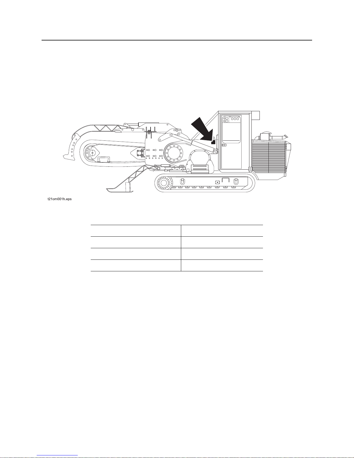
Record serial numbers and date of purchase in spaces provided. HT220 serial number is located as
shown.
Date of manufacture
Date of purchase
HT220 serial number
Engine serial number
CMW
Page 4
HT220 Operator’s Manual Overview - 3
Intended Use
Intended Use
The HT220 is a large track trencher designed dig tren ches up to 24” (609 mm) wide and 96” (2.44 m) deep.
The trencher’s hard metal teeth remove very hard, rocky ground and thinly crush it. T he resu lt is an even ,
rectangular-shaped trench ready fro laying pipes or cables.
The unit is designed for operation in temperatures typically experienced in earth moving and construction
work environments. Provisions may be required to operate in extreme temperatures. Contact your Ditch
Witch dealer.
The HT220 should be used with genuine Ditch Witch chain, teeth, and sprockets. It should be operated,
serviced, and repaired only by persons familiar with its particular characteristics and acquainted with the
relevant safety procedures.
Use in any other way is considered contrary to the intended use.
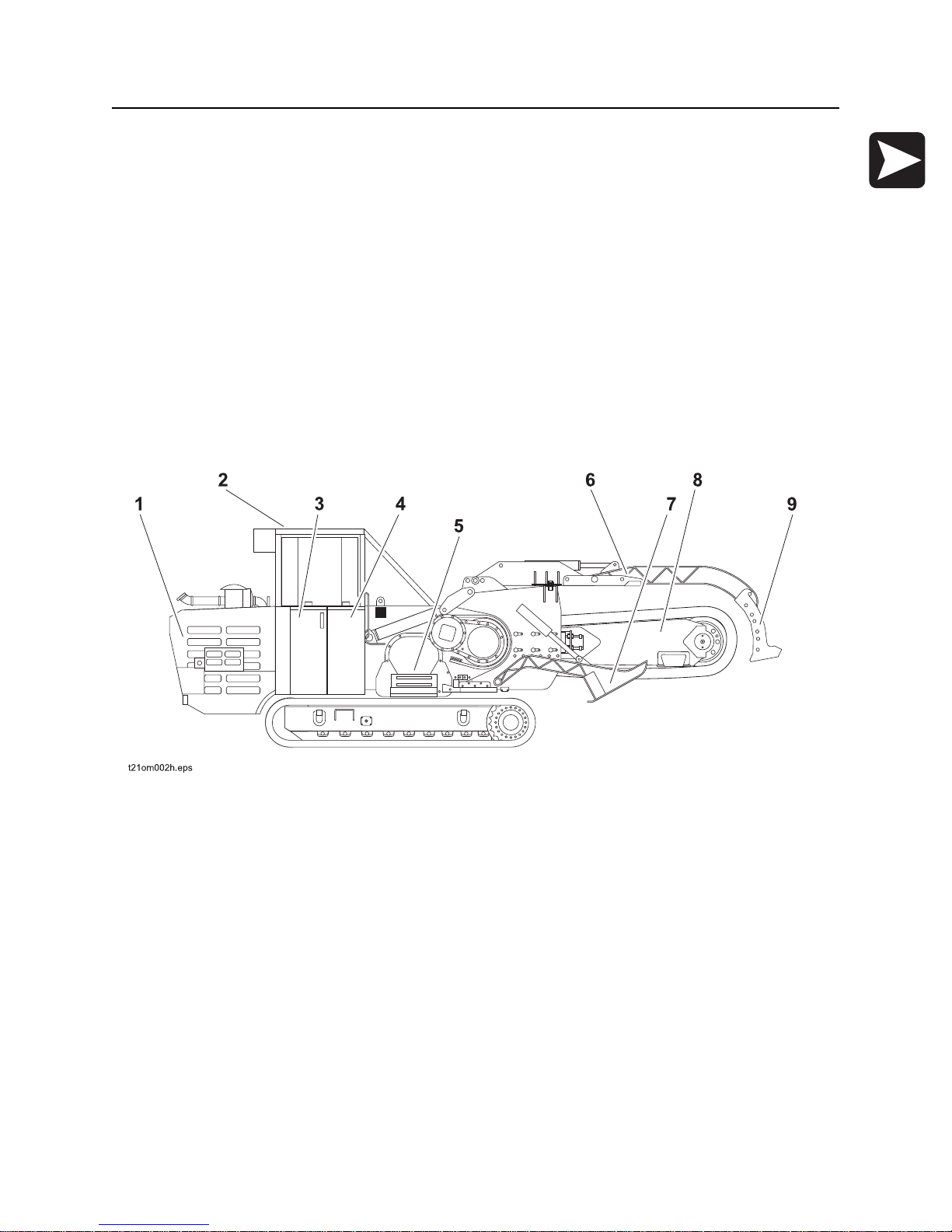
Unit Components
1. engine compartment
2. operator’s station
3. hydraulic reservoir
4. fuel tank
5. conveyor
6. trench cleaner
7. stabilizer
8. digging boom
9. trench cleaner shoe
CMW
Page 5
Overview - 4 HT220 Operator’s Manual
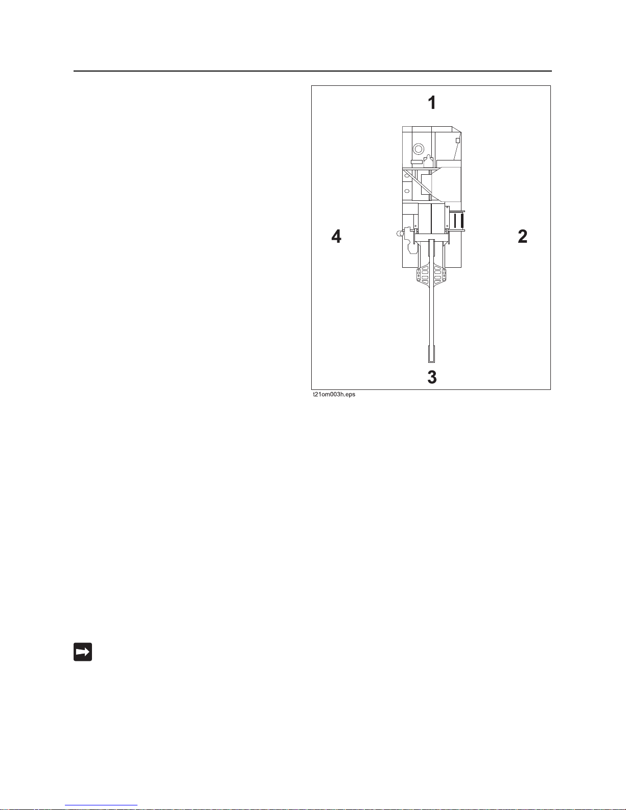
Operator Orientation
Operator Orientation
1. Front of unit
2. Right of unit
Right and left sides of machine are determined by
facing front of unit while seated at the controls.
3. Rear of unit
4. Left of unit
About This Manual
This manual contains information for the proper use of this machine. See Operation Overview for basic
operating procedures. Cross references such as “See page 50” will direct you to detailed procedures.
Bulleted Lists
Bulleted lists provide helpful or important information or contain procedures that do not have to be
performed in a specific order.
Numbered Lists
Numbered lists contain illustration callouts or list steps that must be performed in order.
“Continued” Indicators
indicates that a procedure is continued on the next page.
CMW
Page 6

HT220 Operator’s Manual Foreword - 5
Foreword
This manual is an important part of your equipment. It provides safety information and operation
instructions to help you use and maintain your Ditch Witch equipment.
Read this manual before using your equipment. Keep it with the equipmen t at all times for future reference.
If you sell your equipment, be sure to give this manual to the new owner.
If you need a replacement copy, contact your Ditch Witch dealer. If you need assistance in locating a
dealer, visit our website at www.ditchwitch.com or write to the following address:
The Charles Machine Works, Inc.
Attn: Marketing Department
PO Box 66
Perry, OK 73077-0066
USA
The descriptions and specifications in this manual are subject to change without notice. The Charles
Machine Works, Inc. reserves the right to improve equipment. Some product improvements may have
taken place after this manual was publishe d. For the latest information on Ditch Witch equipment, see your
Ditch Witch dealer.
Thank you for buying and using Ditch Witch equipment.
CMW
Page 7

Foreword - 6 HT220 Operator’s Manual
HT220
Operator’s Manual
Issue number 1.0/OM-4/07
Part number 053-1130
Copyright 2007
by The Charles Machine Works, Inc.
, Ditch Witch, CMW, AutoCrowd, Modularmatic, Jet Trac, Roto Witch, Subsite,
Fluid Miser, Perma-Soil, Power Pipe, Super Witch, Super Witch II, Pierce Airrow, The Underground, and
The Underground Authority Worldwide are r egistered trademarks of The Charles Machine Works, Inc.
CMW
Page 8
HT220 Operator’s Manual Contents - 7
Contents
Overview
machine serial number, information about the type of work this machine is designed
to perform, basic machine components, and how to use this manual
Foreword
part number, revision level, and publication date of this manual, and factory contact
information
Safety
machine safety alerts and emergency procedures
Controls
machine controls, gauges, and indicators and how to use them
Operation Overview
an overview for completing a job with this machine: planning, setting up, installing
product, and restoring the jobsite; with cross references to deta iled procedures
Prepare
procedures for inspecting and classifying the jobsite, planning the installation path,
and preparing the jobsite for work
Drive
procedures for startup, cold start, driving, and shutdown
1
5
9
21
19
41
53
Transport
procedures for lifting, hauling, and towing
Trench
procedures for trenching
Systems and Equipment
chain, teeth, sprockets, and optional equipment
Complete the Job
procedures for backfilling and restoring the jobsite and rinsing and storing
equipment
Service
service intervals and instructions for this machine including lubrication, replacement
of wear items, and basic maintenance
59
67
73
93
95
CMW
Page 9

Contents - 8 HT220 Operator’s Manual
Specifications
machine specifications including weights, measurements, power ratings, and fluid
capacities
Support
the warranty policy for this machine, and procedures for obtaining warranty
consideration and training
Service Record
a record of major service performed on the machine
117
139
143
CMW
Page 10

HT220 Operator’s Manual Safety - 9
Safety
Chapter Contents
Guidelines . . . . . . . . . . . . . . . . . . . . . . . . . . . . . . . . 10
Safety Alert Classifications . . . . . . . . . . . . . . . . . . 11
Safety Alerts . . . . . . . . . . . . . . . . . . . . . . . . . . . . . . 12
Emergency Procedures . . . . . . . . . . . . . . . . . . . . . 15
• Electric Strike Description. . . . . . . . . . . . . . . . . . . . . . . . . . . . . . . . . . . .15
• If an Electric Line is Damaged . . . . . . . . . . . . . . . . . . . . . . . . . . . . . . . .16
• If a Gas Line is Damaged . . . . . . . . . . . . . . . . . . . . . . . . . . . . . . . . . . . .17
• If a Fiber Optic Cable is Damaged . . . . . . . . . . . . . . . . . . . . . . . . . . . . .17
• If Machine Catches on Fire. . . . . . . . . . . . . . . . . . . . . . . . . . . . . . . . . . .17
CMW
Page 11

Safety - 10 HT220 Operator’s Manual
Guidelines
Guidelines
Follow these guidelines before operating any jobsite equipment:
• Complete proper training and read operator’s manual before using equipment.
• Contact your local One-Call service by dialing 811 (USA only) to have underground utilities located. A
One-Call referral number, 888-258-0808, is also available for both the USA and Canada. You should
also call any utility companies which do not participate in the One-Call service.
• Classify jobsite based on its hazards and use correct tools and machin ery, safety equipment, and work
methods for jobsite.
• Mark jobsite clearly and keep spectators away.
• Wear personal protective equipment.
• Review jobsite hazards, safety and emergency procedures, and individual responsibilities with all
personnel before work begins. Safety videos are available from your Ditch Witch dealer.
• Replace missing or damaged safety shields and safety signs.
• Use equipment carefully. Stop operation and investigate anything that does not look or feel right.
• Do not operate unit where flammable gas is present.
• Contact your Ditch Witch dealer if you have any question about operation, ma intenance, or equipmen t
use.
CMW
Page 12

HT220 Operator’s Manual Safety - 11
Safety Alert Classifications
Safety Alert Classifications
These classifications and the icons defined on the following pages work together to alert you to situations
which could be harmful to you, jobsite bystanders or your equipment. When you see these words and
icons in the book or on the machine, carefully read and follow all instructions. YOUR SAFETY IS AT
STAKE.
Watch for the three safety alert levels: DANGER, WARNING and CAUTION. Learn what each level
means.
indicates an imminently hazardous situation which, if not avoided, will result in death or
serious injury.
indicates a potentially hazardous situation which, if not avoided, could result in death or
serious injury.
indicates a potentially hazardous situation which, if not avoided, may result in minor or
moderate injury.
Watch for two other words: NOTICE and IMPORTANT.
NOTICE can keep you from doing something that might damage the machine or someone's property. It
can also alert you against unsafe practices.
IMPORTANT can help you do a better job or make your job easier in some way.
CMW
Page 13
Safety - 12 HT220 Operator’s Manual
Safety Alerts
Safety Alerts
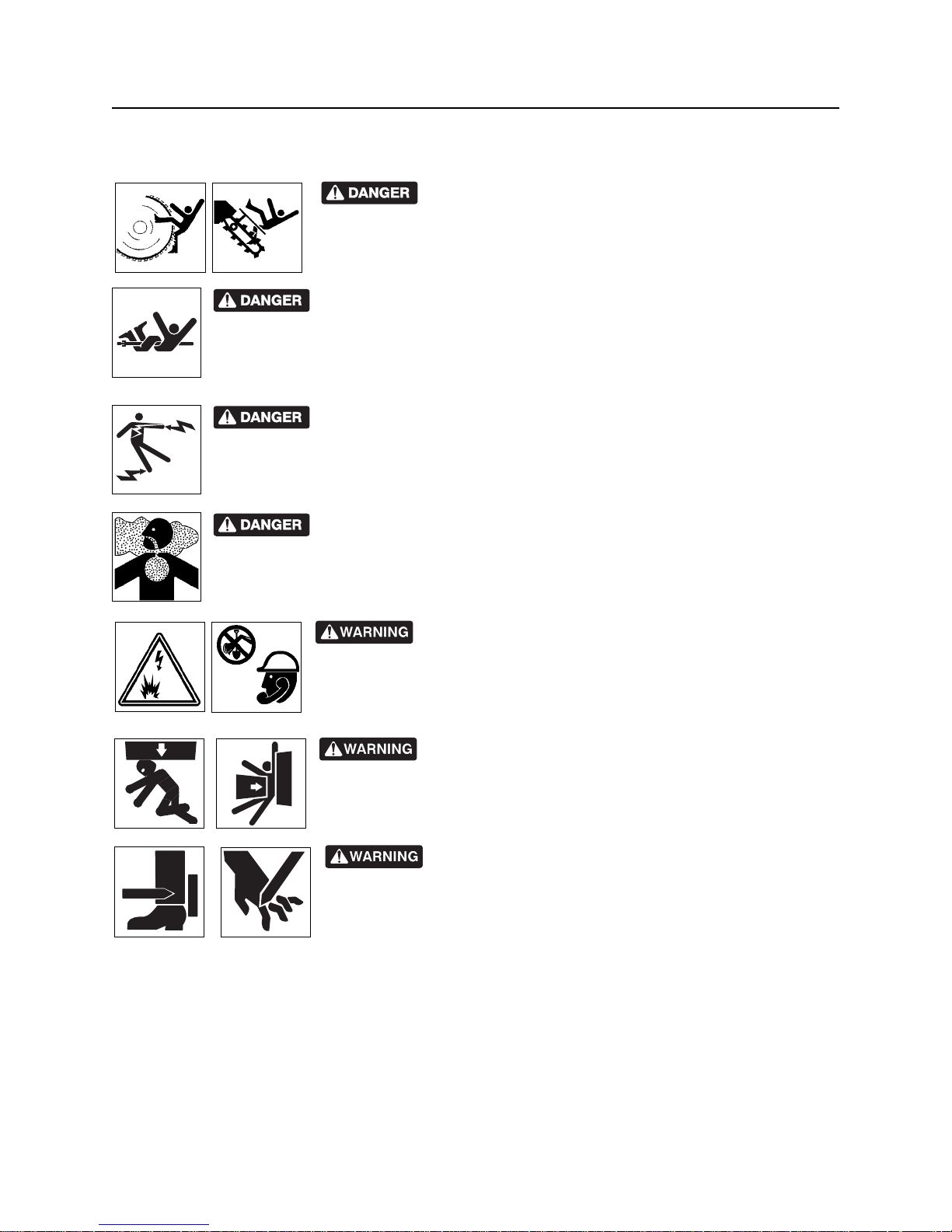
Moving digging teeth will kill you or cut off arm or leg. Stay
away .
Turning shaft will kill you or crush arm or leg. Stay away.
Electric shock. Contacting electric lines will cause death or serious injury.
Know location of lines and stay away.
Deadly gases. Lack of oxygen or presence of gas will cause sickness or
death. Provide ventilation.
correct equipment and work methods. Use and maintain proper safety
equipment.
proper procedures and equipment or stay away.
Jobsite hazards could cause death or serious injury. Use
Crushing weight could cause death or seriou s injur y. Use
Moving parts could cut off ha nd or foot. Stay away.
CMW
Page 14
HT220 Operator’s Manual Safety - 13
Safety Alerts
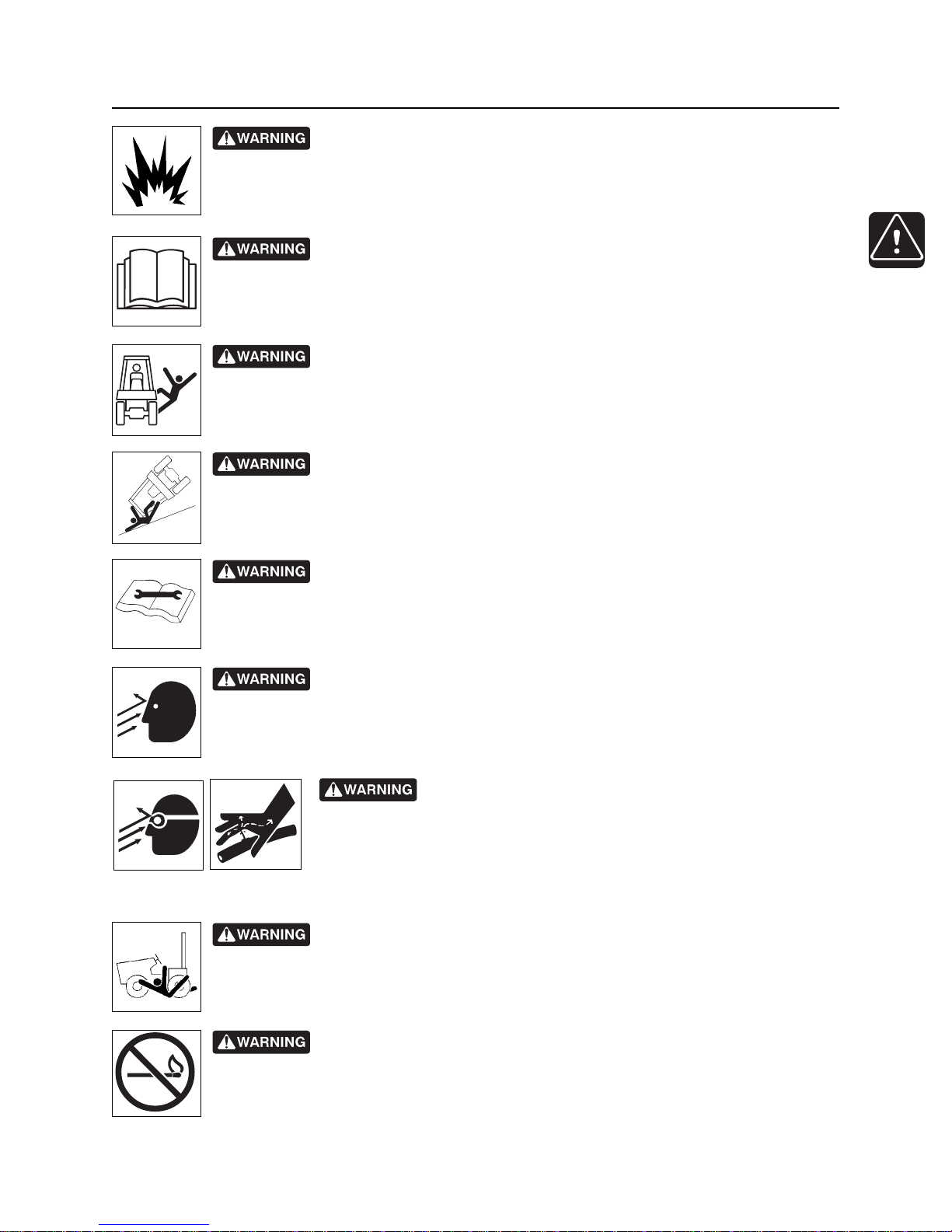
Explosion possible. Serious injury or equipment damage could occur.
Follow directions carefully.
Incorrect procedures could result in death, injury, or property damage.
Learn to use equipment correctly.
Fall possible. Riders can fall from machine and be injured or killed. Only
operator is allowed on machine.
Rollover possible. If machine rolls over, you could be thrown from seat and
killed or crushed. Wear seat belt.
Improper control function could cause death or serious injury. If control does
not work as described in instructions, stop machine and have it serviced.
Looking into fiber optic cable could result in permanent vision damage. Do
not look into ends of fiber optic or unidentified cable.
Pressurized fluid or air could pierce skin a nd cause injur y or
death. Stay away.
Runaway possible. Machine could run over you or others. Learn how to use
all controls. Start and operate only from operator’s position.
smoking, no flame, no spark.
Fire or explosion possible. Fumes could ignite and cause burns. No
CMW
Page 15
Safety - 14 HT220 Operator’s Manual
Safety Alerts
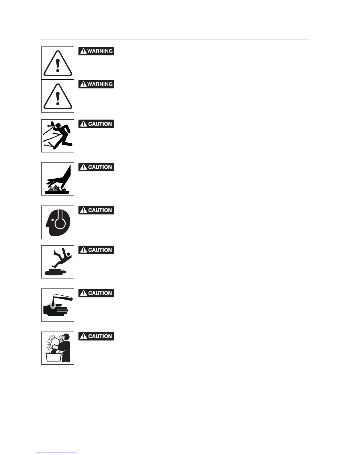
Moving traffic - hazardous situation. Death or serious injury could result.
Avoid moving vehicles, wear high visibility clothing, post appropriate warning signs.
Hot pressurized cooling system fluid could cause serious burns. Allow to
cool before servicing.
Flying objects may cause injury. Wear hard hat and safety glasses.
Hot parts may cause burns. Do not touch until cool.
Exposure to high noise levels may cause hearing loss. Wear hearing
protection.
Fall possible. Slips or trips may result in injury. Keep area clean.
Battery acid may cause burns. Avoid contact.
Improper handling or use of chemicals may result in illness, injury, or
equipment damage. Follow instructions on labels and in material safety da ta sheets
(MSDS).
CMW
Page 16
HT220 Operator’s Manual Safety - 15
Emergency Procedures
Emergency Procedures
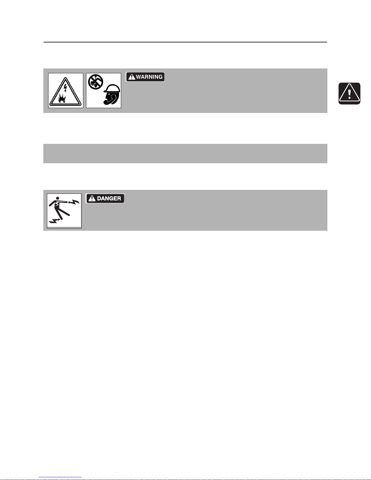
Jobsite hazards could cause death or serious injury. Use
correct equipment and work methods. Use and maintain proper safety
equipment.
Before operating any equipment, review emergency proc edures and check that all safety precau tions have
been taken.
EMERGENCY SHUTDOWN - Turn ignition switch to stop position or push remote e ngine stop button ( if
equipped).
Electric Strike Description
Electric shock. Contacting electric lines will cause death or serious injury.
Know location of lines and stay away.
When working near electric cables, remember the following:
• Electricity follows all paths to ground, not just path of least resistance.
• Pipes, hoses, and cables will conduct electricity back to all equipment.
• Low voltage current can injure or kill. Almost one-third of work-related electrocutions result from
contact with less than 440 volts.
Most electric strikes are not noticeable, but indications of a strike include:
• power outage
•smoke
•explosion
• popping noises
• arcing electricity
If any of these occur, assume an electric strike has occurred.
CMW
Page 17

Safety - 16 HT220 Operator’s Manual
Emergency Procedures
If an Electric Line is Damaged
If you suspect an electric line has been damaged and you are on tractor, DO NOT MOVE. Remain on
tractor and take the following actions. The order and degree of action will depend upon the situation.
• Warn people nearby that an electric strike has occurred. Instruct them to leave the area and contact
utility.
• Raise attachments and drive from immediate area.
• Contact utility company to shut off power.
• Do not return to jobsite or allow anyone into area until given permission by utility company.
If you suspect an electric line has been damaged and you are off tractor, DO NOT TOUCH TRACTOR.
Take the following actions. The order and degree of action will depend upon the situation.
• LEAVE AREA. The ground surface may be electrified, so take small steps with feet close together to
reduce the hazard of being shocked from one foot to the other. For more information, contact your
Ditch Witch dealer.
• Contact utility company to shut off power.
• Do not return to jobsite or allow anyone into area until given permission by utility company.
CMW
Page 18
HT220 Operator’s Manual Safety - 17
Emergency Procedures
If a Gas Line is Damaged
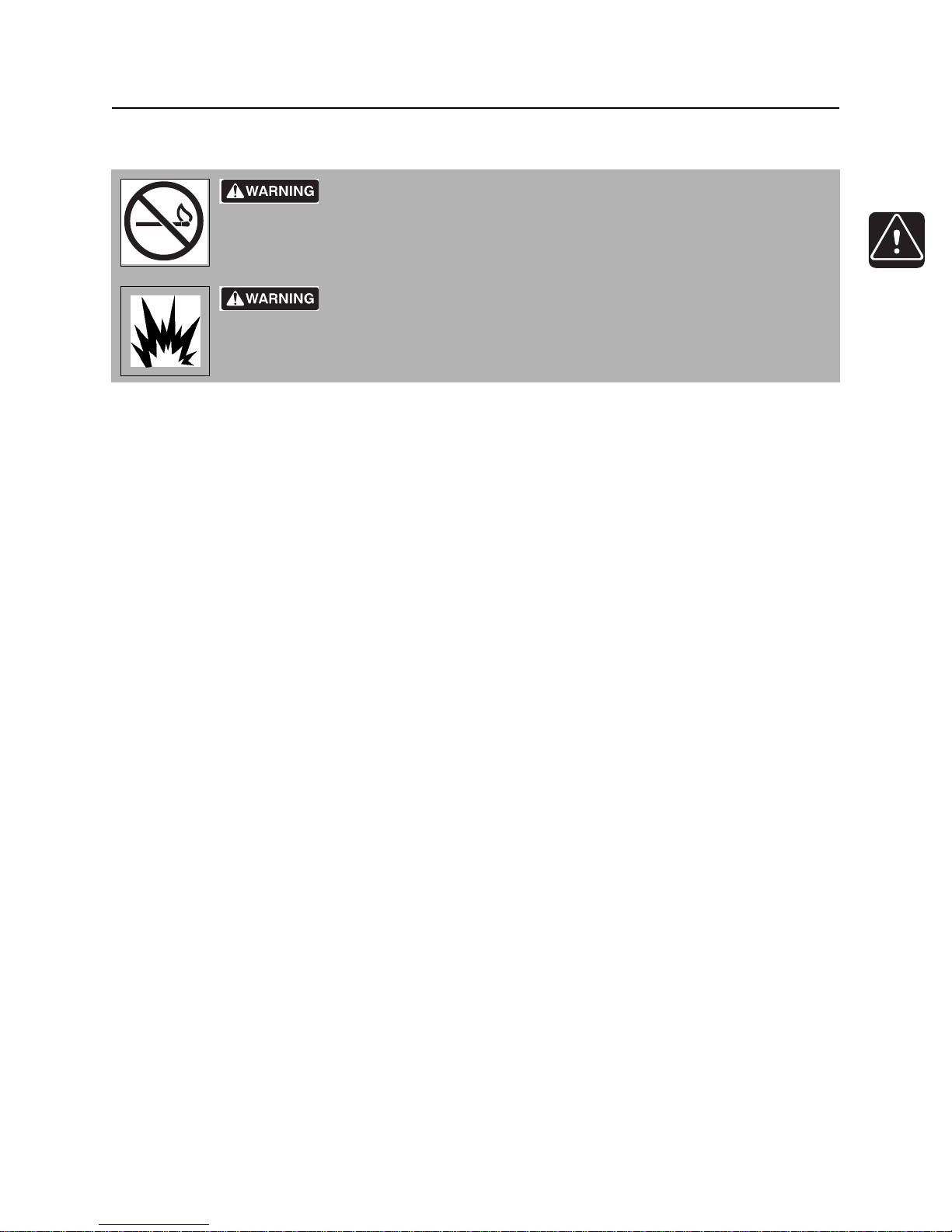
Fire or explosion possible. Fumes could ignite and cause burns. No
smoking, no flame, no spark.
Explosion possible. Serious injury or equipment damage could occur.
Follow directions carefully.
If you suspect a gas line has been damaged, take the following actions. The order and degree of action will
depend on the situation.
• Immediately shut off engine(s), if this can be done safely and quickly.
• Remove any ignition source(s), if this can be done safely and quickly.
• Warn others that a gas line has been cu t and that they sh ould leave the area.
• Leave jobsite as quickly as possible.
• Immediately call your local emergency phone number and utility company.
• If jobsite is along street, stop traffic from driving near jobsite .
• Do not return to jobsite until given permission by emergency personnel and utility company.
If a Fiber Optic Cable is Damaged
Do not look into cut ends of fiber optic or unidentified cable. Vision damage can occur.
If Machine Catches on Fire
Perform emergency shutdown procedure and then take the following actions. The order and degree of
action will depend on the situation.
• Immediately move battery disconnect switch (if equipped) to disconnect position.
• If fire is small and fire extinguisher is available, attempt to extinguish fire.
• If fire cannot be extinguished, leave area as quickly as possible and contact emergency personnel.
CMW
Page 19

Safety - 18 HT220 Operator’s Manual
Emergency Procedures
CMW
Page 20

HT220 Operator’s Manual Operation Overview - 19
Operation Overview
Chapter Contents
Planning. . . . . . . . . . . . . . . . . . . . . . . . . . . . . . . . . . 20
Trenching. . . . . . . . . . . . . . . . . . . . . . . . . . . . . . . . . 20
Leaving Jobsite. . . . . . . . . . . . . . . . . . . . . . . . . . . . 20
CMW
Page 21

Operation Overview - 20 HT220 Operator’s Manual
Planning
Planning
1. Gather information about jobsite. See page 42.
2. Inspect jobsite. See page 43.
3. Classify jobsite. See page 44.
4. Select chain and teeth to match your soil type, if necessary. See page 78.
5. Check supplies and prepare equipment. See page 46.
6. Haul equipment to jobsite. See page 54.
Trenching
1. Start unit. See page 48.
2. Position tractor and controls. See page 60.
3. Begin trenching. See page 61.
4. Complete the installation. See page 61.
5. Shut down tractor. See page 50.
Leaving Jobsite
1. Rinse equipment. See page 82.
2. Stow tools. See page 82.
3. Haul equipment away from jobsite. See page 54.
CMW
Page 22

HT220 Operator’s Manual Controls - 21
Controls
Chapter Contents
Center Console . . . . . . . . . . . . . . . . . . . . . . . . . . . 22
• Switches . . . . . . . . . . . . . . . . . . . . . . . . . . . . . . . . . . . . . . . . . . . . . . . . .22
• Indicators . . . . . . . . . . . . . . . . . . . . . . . . . . . . . . . . . . . . . . . . . . . . . . . .24
• Trenching Controls . . . . . . . . . . . . . . . . . . . . . . . . . . . . . . . . . . . . . . . . .28
• Gauges . . . . . . . . . . . . . . . . . . . . . . . . . . . . . . . . . . . . . . . . . . . . . . . . . .31
• Drive Controls . . . . . . . . . . . . . . . . . . . . . . . . . . . . . . . . . . . . . . . . . . . .34
Diagnostic Display . . . . . . . . . . . . . . . . . . . . . . . . . 37
Seat . . . . . . . . . . . . . . . . . . . . . . . . . . . . . . . . . . . . . 39
Top Console . . . . . . . . . . . . . . . . . . . . . . . . . . . . . . 40
Heater Controls . . . . . . . . . . . . . . . . . . . . . . . . . . . 42
Battery Disconnects . . . . . . . . . . . . . . . . . . . . . . . 43
Emergency Stop . . . . . . . . . . . . . . . . . . . . . . . . . . . 45
CMW
Page 23
Controls - 22 HT220 Operator’s Manual
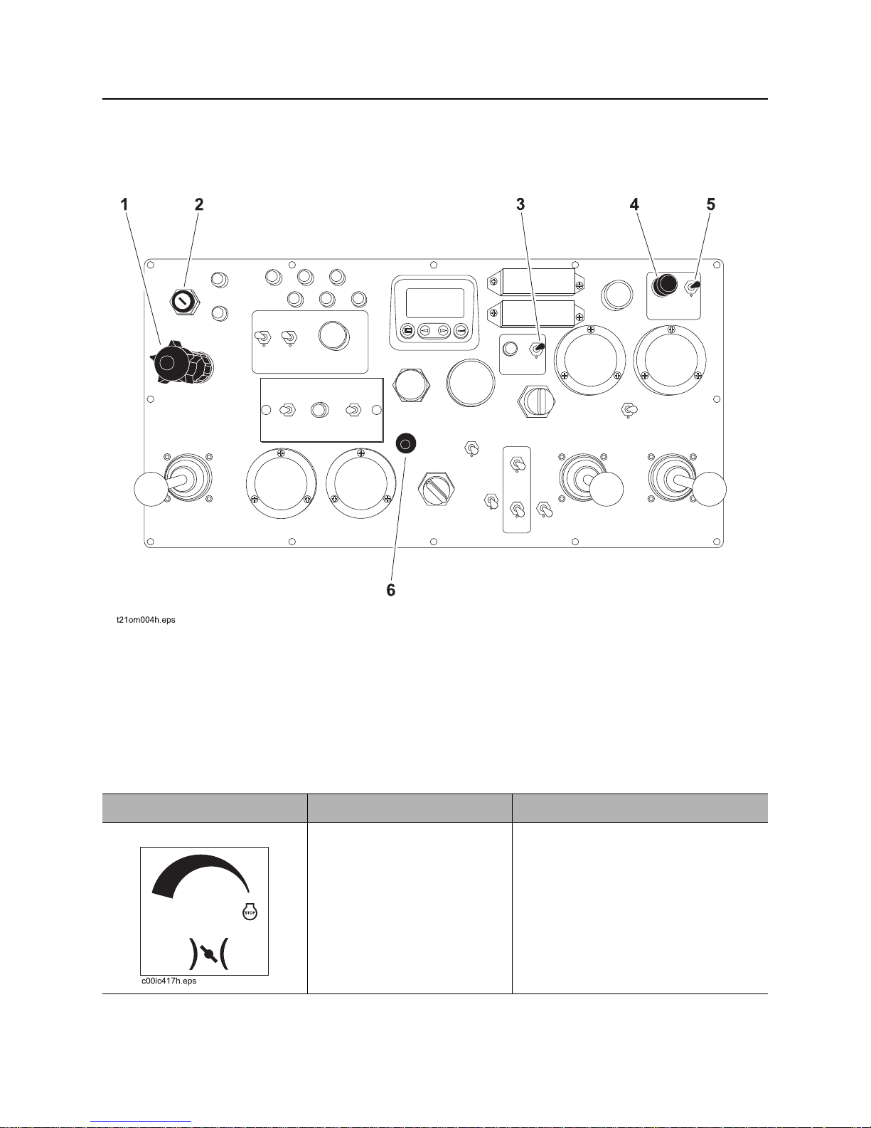
Center Console
Center Console
Switches
1. Throttle
2. Engine Ignition Switch
3. Low Hydraulic Fluid Test Switch
Item Description Notes
1. Throttle T o incr ease throttle, turn knob
counterclockwise.
To idle, push knob in.
CMW
4. Light Control
5. Light Switch
6. Horn
Page 24
HT220 Operator’s Manual Controls - 23
Center Console
Item Description Notes
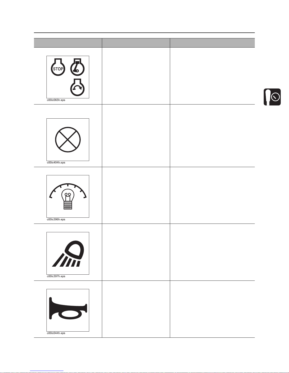
2. Engine Ignition Switch T o star t engine, insert key and
turn clockwise.
To stop engine, turn
counterclockwise.
3. Low Hydraulic Fluid
Test Switch
4. Light Control To adjust inside light level,
5. Light Switch To turn on lights, move to up
To check for low hydraulic
fluid, move to down position.
turn knob.
position.
To turn off lights, move to
down position.
Switch is normally centered.
6. Horn To sound horn, press.
CMW
Page 25
Controls - 24 HT220 Operator’s Manual
Center Console
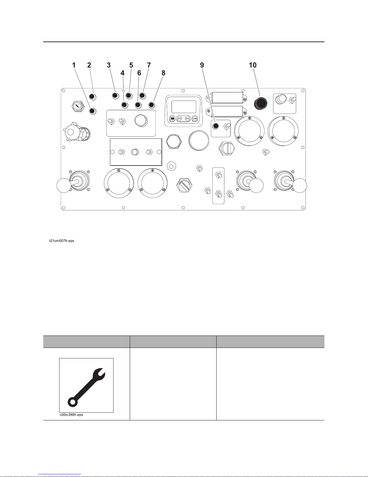
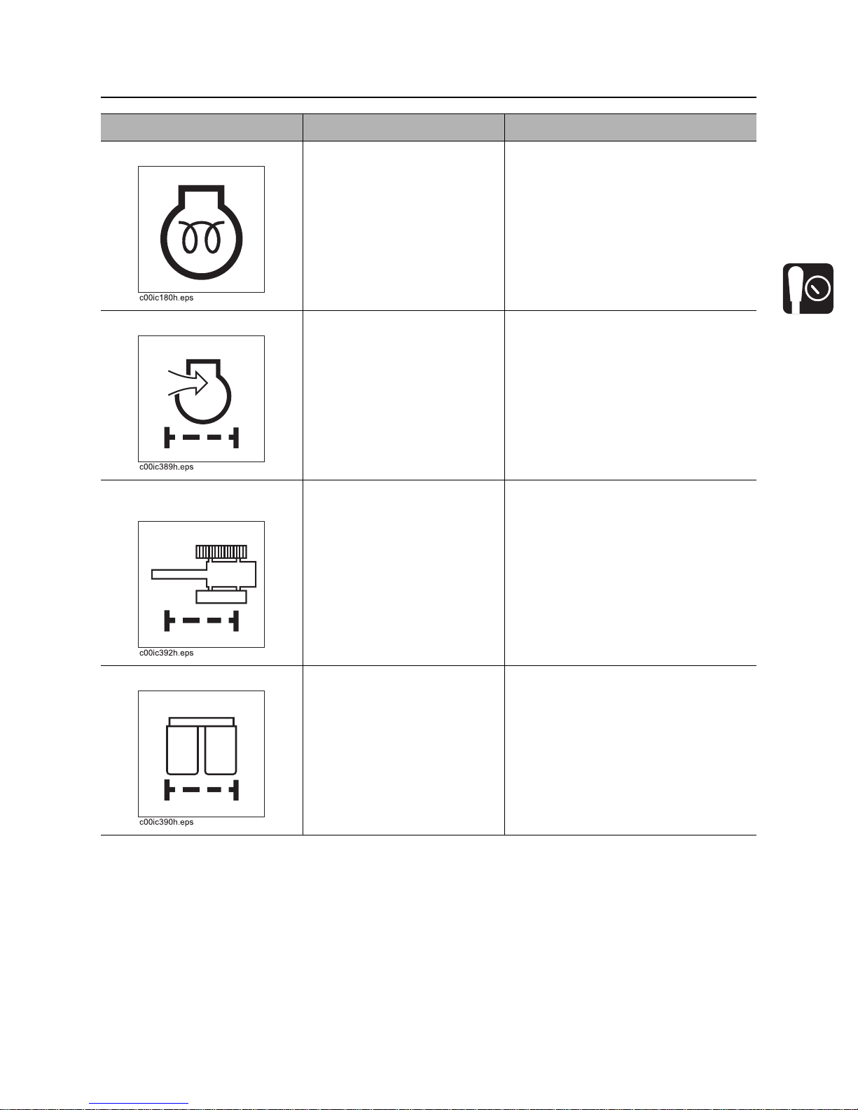
Indicators
1. Maintenance Indicator
2. Wait to Start Indicator
3. Air Filter Indicator
4. Left Track Filter Indicator
5. Double Filter Indicator
Item Description Notes
1. Maintenance Indicator Light will come on when the
engine needs maintenance.
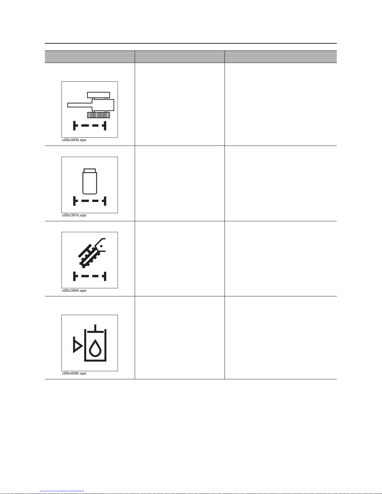
6. Right Track Filter Indicator
7. Single Filter Indicator
8. Digging Filter Indicator
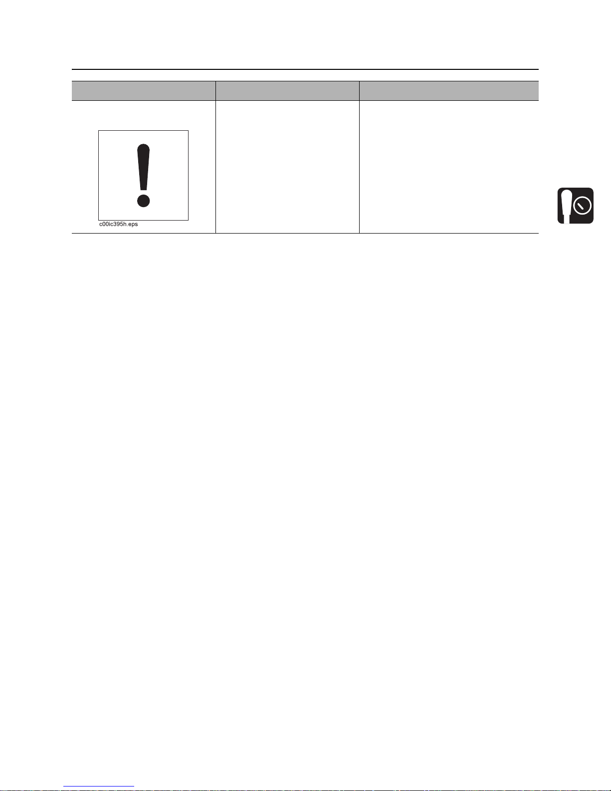
9. Low Hydraulic Fluid Indicator
10. Warning Ignition “ON” Indicator
CMW
Page 26
HT220 Operator’s Manual Controls - 25
Center Console
Item Description Notes
2. Wait to Start Indicator Light goes out when engine is
ready to start.
3. Air Filter Indicator Light comes on when the air
filter is dirty.
4. Left Track Filter
Indicator
5. Double Filter Indicator Comes on when the double
Light comes on when the left
track filter needs replacing.
filter needs replacing.
CMW
Page 27
Controls - 26 HT220 Operator’s Manual
Center Console
Item Description Notes
6. Right Track Filter
Indicator
7. Single Filter Indicator Light comes on when the
8. Digging Filter Indicator Light comes on when the
Light comes on when the right
track filter needs replacing.
single filter needs replacing.
digging filter needs replacing.
9. Low Hydraulic Fluid
Indicator
CMW
Illuminates when low fluid
switch is pressed and fluid is
low.
Page 28
HT220 Operator’s Manual Controls - 27
Center Console
Item Description Notes
10. War ning Ignition “On”
Indicator
Buzzer sounds when engine
is not running and the ignition
switch is on.
CMW
Page 29
Controls - 28 HT220 Operator’s Manual
Center Console
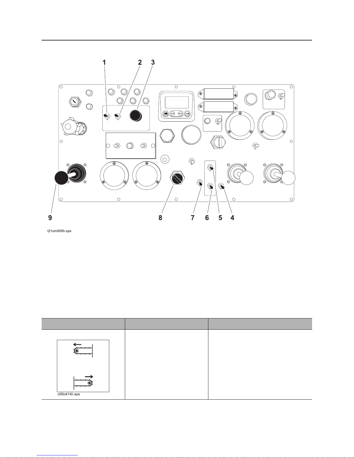
Trenching Controls
1. Conveyor Shift Control
2. Conveyor Direction Control
3. Conveyor Speed Control
4. Trench Cleaner Control
5. Stabilizer Control
Item Description Notes
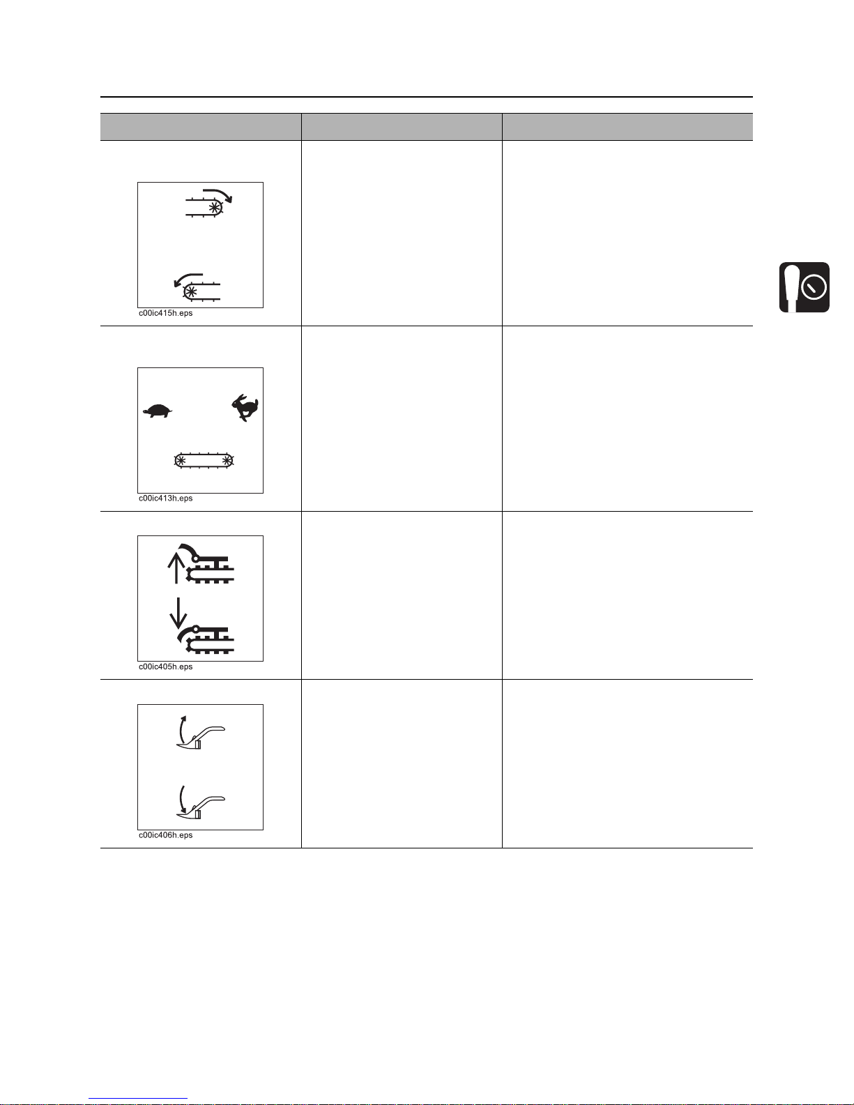
1. Conveyor Shift Control To shift left, move to up
position.
To shift right, move to down
position.
6. Auto Stabilizer Control
7. Boom Lift Control
8. Cruise Control Set Control
9. Trencher Drive Control
CMW
Page 30
HT220 Operator’s Manual Controls - 29
Center Console
Item Description Notes
2. Conveyor Direction
Control
3. Conveyor Speed
Control
4. Trench Clea ner Control To raise trench cleaner, press
To dump spoil to the left,
press down.
To dump spoil to the right,
press up.
To increase conveyor belt
speed, turn clockwise.
To decrease conveyor belt
speed, turn counterclockwise.
up.
T o lower trench cleaner, press
down.
5. Stabilizer Control To raise stabilizers, push up.
To lower stabilizers, pull
down.
CMW
Page 31
Controls - 30 HT220 Operator’s Manual
Center Console
Item Description Notes
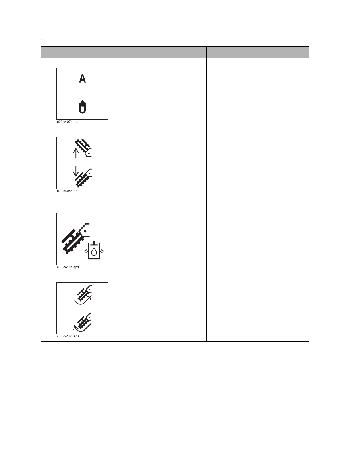
6. Auto Stabilizer Control For automatic stabilizers,
push up.
For manual stabilizers, pull
down.
7. Boom Lift Control To raise boom, push up.
To lower boom, pull down.
8. Cruise Control Set
Control
9. Trencher Drive Control To rotate trencher forward,
To set cruise control, turn
knob.
push up.
To rotate trencher backward,
pull down.
CMW
Page 32
HT220 Operator’s Manual Controls - 31
Center Console
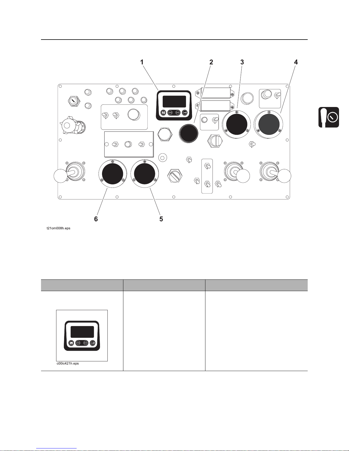
Gauges
1. Diagnostic Display Gauge
2. Hydraulic Fluid Temperature Gauge
3. Left Track Pressure Gauge
Item Description Notes
1. Diagnostic Display
Gauge
Digital display monitors
engine functions.
4. Right Track Pressure Gauge
5. Trencher Pressure Gauge
6. Equipment System Pressure Gauge
See “Top Console ” on page 40.
CMW
Page 33
Controls - 32 HT220 Operator’s Manual
Center Console
Item Description Notes
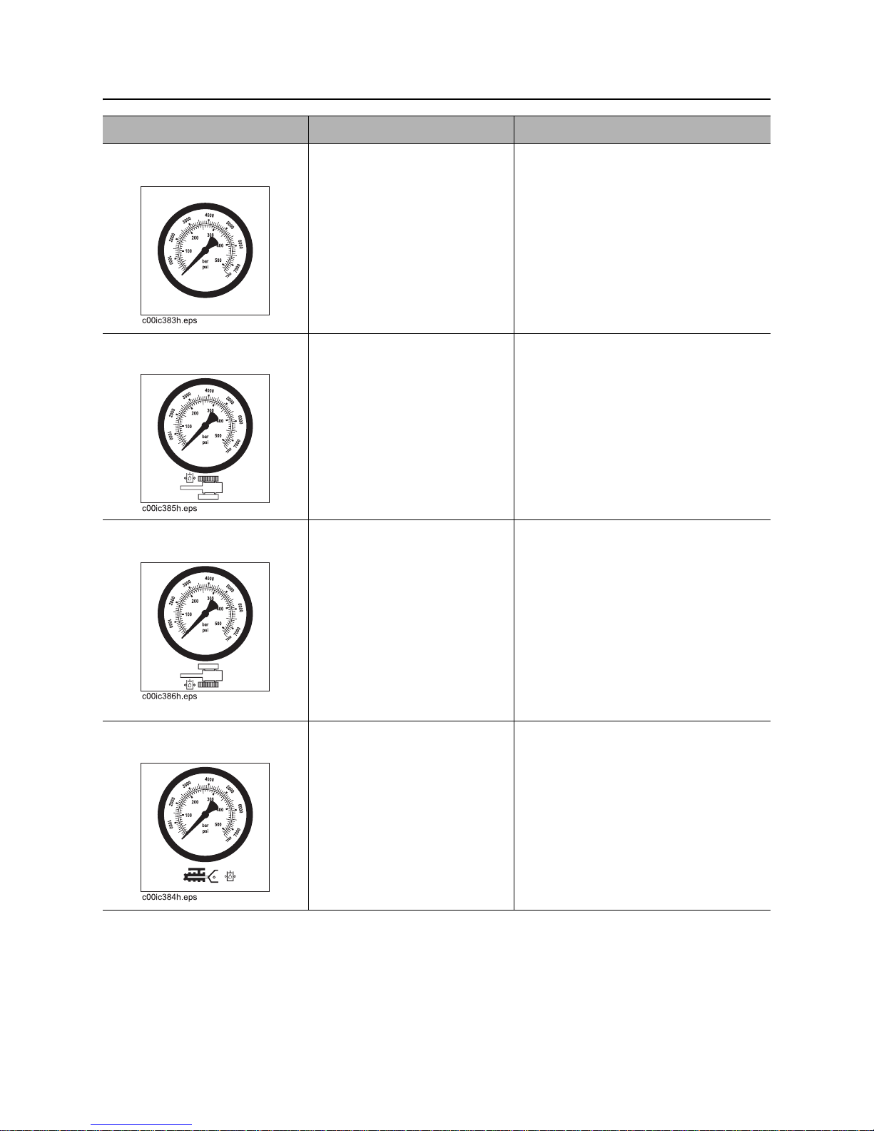
2. Hydraulic Fluid
Temperature Gauge
3. Left Track Pressure
Gauge
4. Right Track Pressure
Gauge
Displays hydraulic fluid
temperature.
Displays hydraulic fluid
pressure at the left track.
Displays hydraulic fluid
pressure at the right track.
Do not exceed 190° F (88° C).
Do not exceed 5,000 PSI (344 bar).
Do not exceed 5,000 PSI (344 bar).
5. Trencher Pressure
Gauge
CMW
Displays hydraulic fluid
pressure at the trencher.
Do not exceed 5,000 PSI (344 bar).
Page 34
HT220 Operator’s Manual Controls - 33
Center Console
Item Description Notes
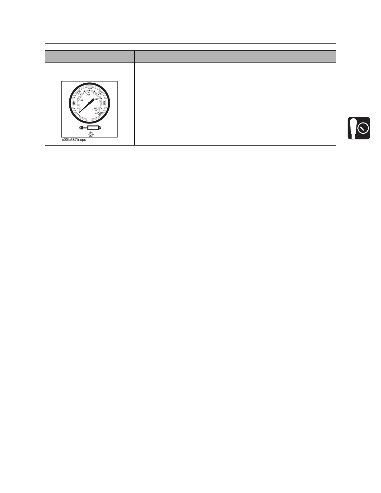
6. Equipment System
Pressure Gauge
Displays hydraulic system
pressure.
Do not exceed 2,500 PSI (172 bar)
CMW
Page 35
Controls - 34 HT220 Operator’s Manual
Center Console
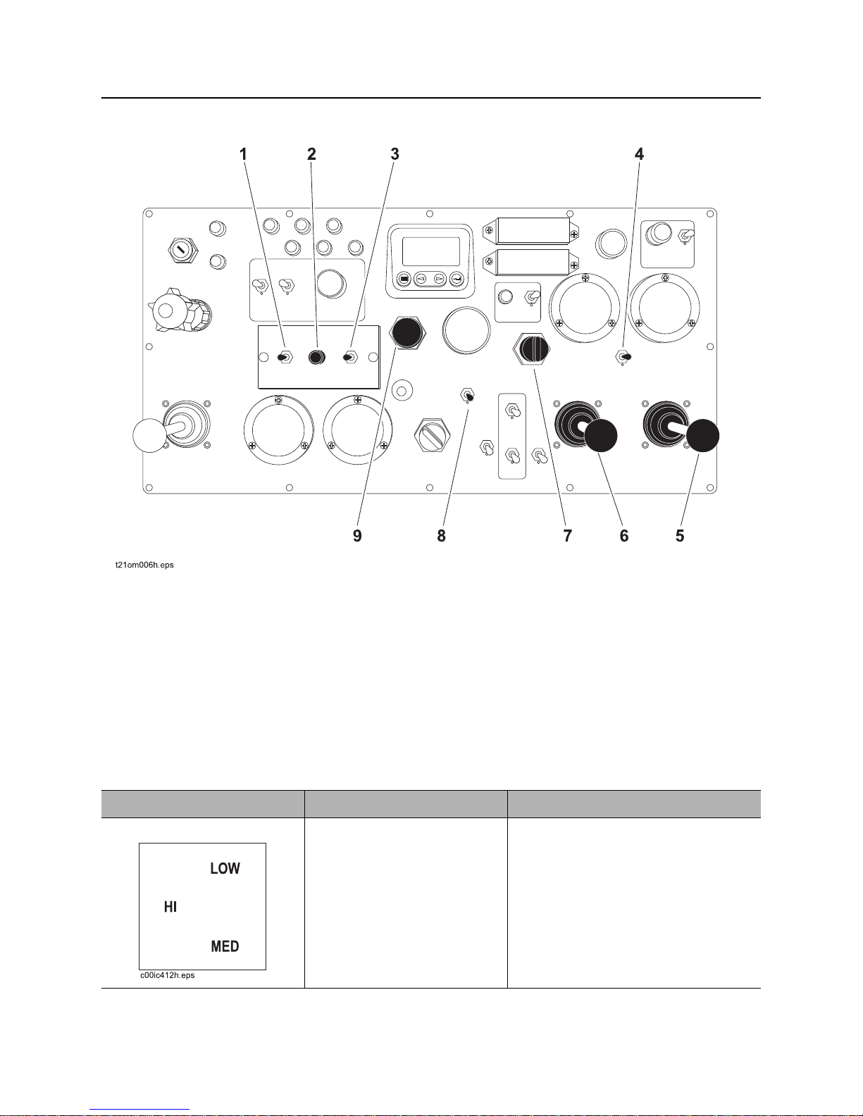
Drive Controls
1. Cruise Control Switch
2. Sensitivity Control
3. auto - manual switch
4. Ground Drive Speed
5. Steering Control
Item Description Notes
1. Cruise Control Switch To position cruise control to
low, push up.
To position cruise control to
medium, pull down.
To position cruise control to
high, place in center.
6. Direction Control
7. Radius Control
8. Parking Brake
9. Emergency Engine Stop
CMW
Page 36
HT220 Operator’s Manual Controls - 35
Center Console
Item Description Notes
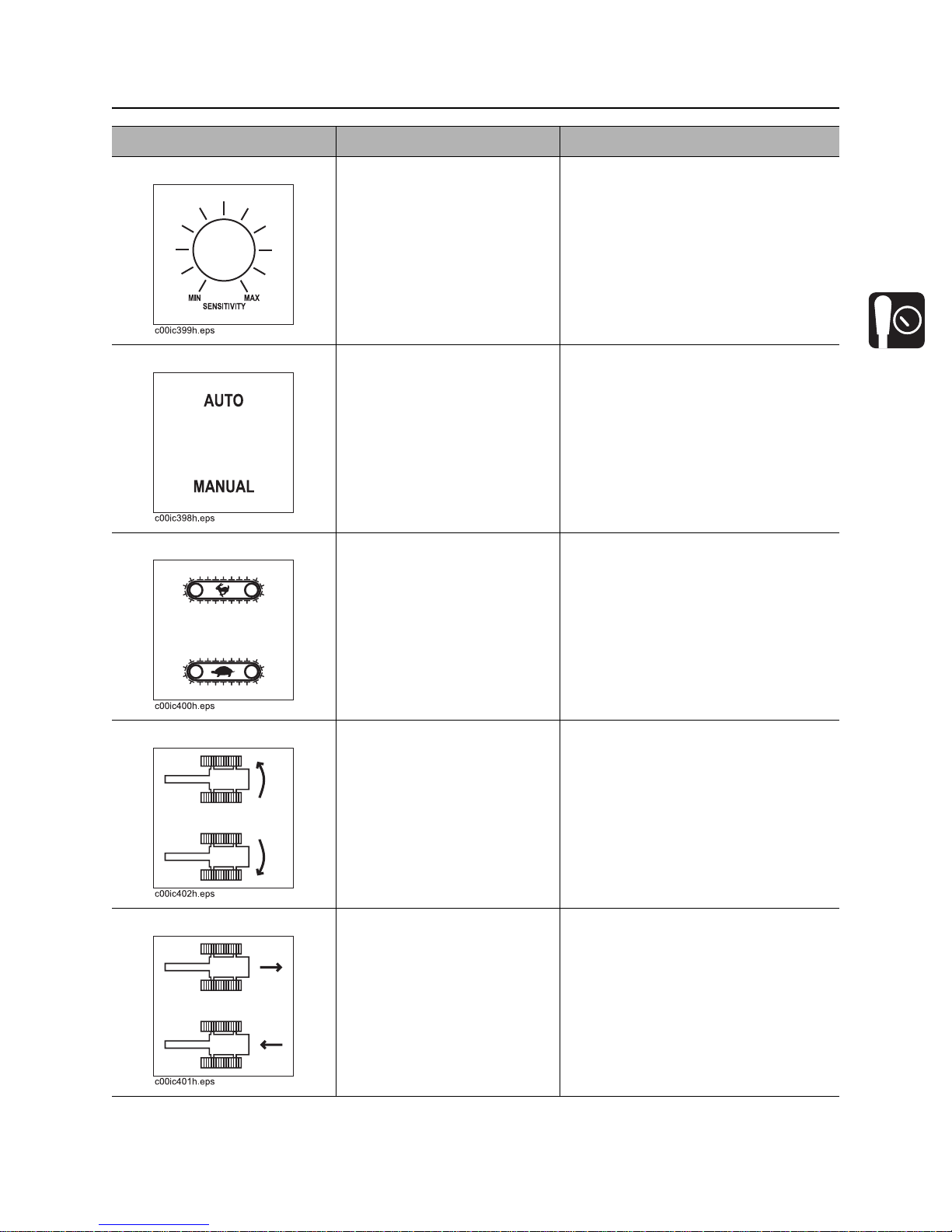
2. Sensitivity Control To decrease sensitivity, turn
left.
To increase sensitivity, turn
right.
3. Auto - Manual Switch To engage cruise control,
push up.
To disengage cruise control,
pull down.
4. Ground Drive Speed To drive in high range, push
up.
To drive in low range, pull
down.
5. Steering Control To steer machine left, move
up.
To steer machine right, move
down.
6. Direction Control To move machine forward,
move up.
To move machine ba ckward,
move down.
Detent lever is normally centered.
Detent lever is normally centered.
CMW
Page 37
Controls - 36 HT220 Operator’s Manual
Center Console
Item Description Notes
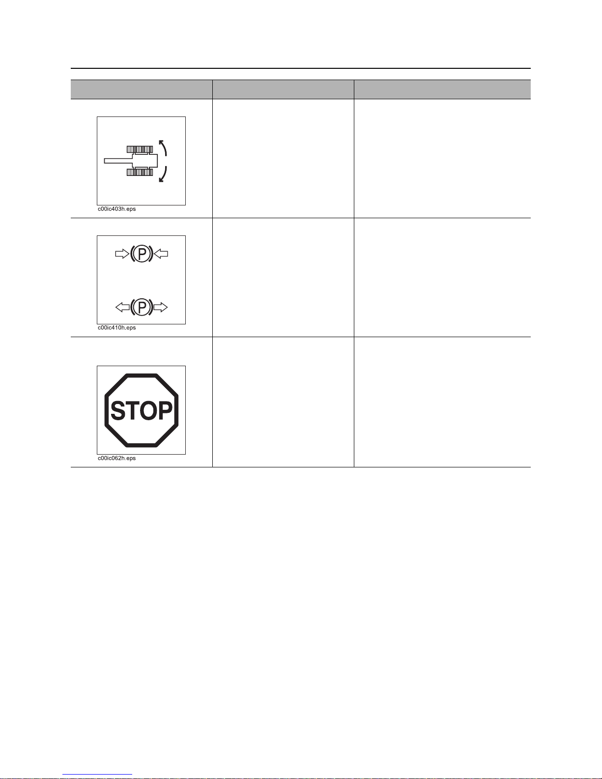
7. Radius Control To increase pressure on the
left track, turn knob to left.
To increase pressure on the
right track, turn knob to the
right.
To equalize pressure, turn
knob to center.
8. Parking Brake T o engage br ake, push switch
up.
To disengage brake, pull
switch down.
9. Emergency Engine
Stop
To stop engine, press button.
T o reset emergency stop, turn
switch to the right.
Do not use emergency engine stop to
stop engine on a regular basis.
CMW
Page 38
HT220 Operator’s Manual Controls - 37
Diagnostic Display
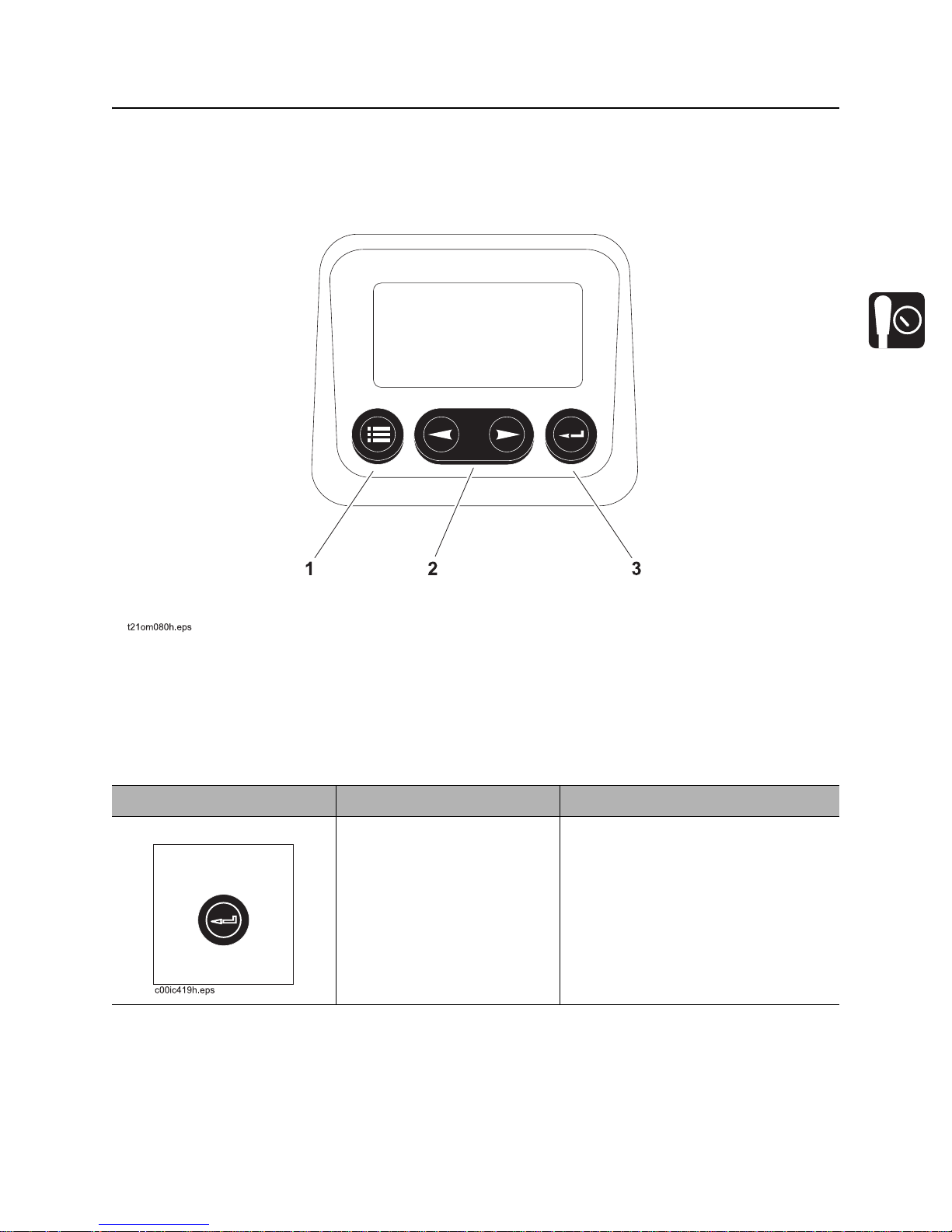
Diagnostic Display
1. Enter Key
2. Arrow Keys
Item Description Notes
1. Enter Key To select the highlighted
parameter on the screen,
touch the ENTER key.
3. Menu Key
CMW
Page 39
Controls - 38 HT220 Operator’s Manual
Diagnostic Display
Item Description Notes
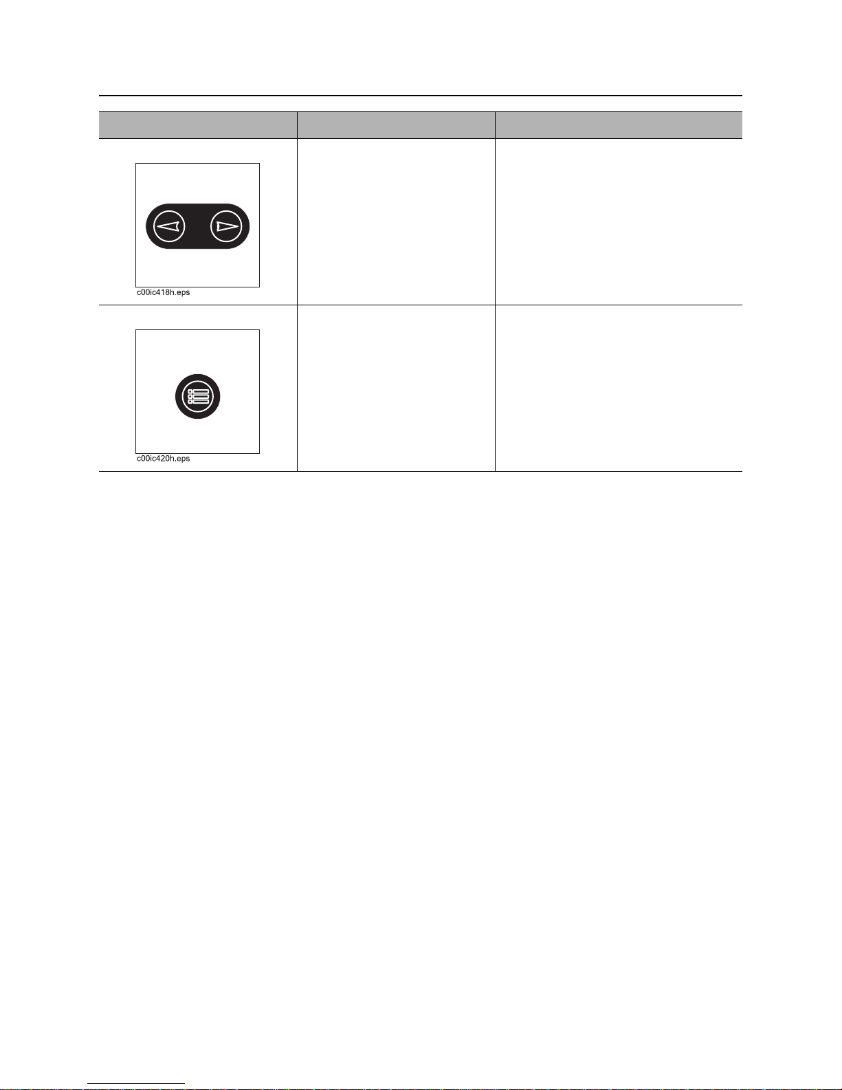
2. Arrow Keys To scroll through the screen
toward the right or downward,
press the Right Arrow key.
To scroll through the screen
toward the left or upward,
press the Left Arrow key.
3. Menu Key To enter or exit the menu
screens, press the Menu key.
CMW
Page 40
HT220 Operator’s Manual Controls - 39
Seat
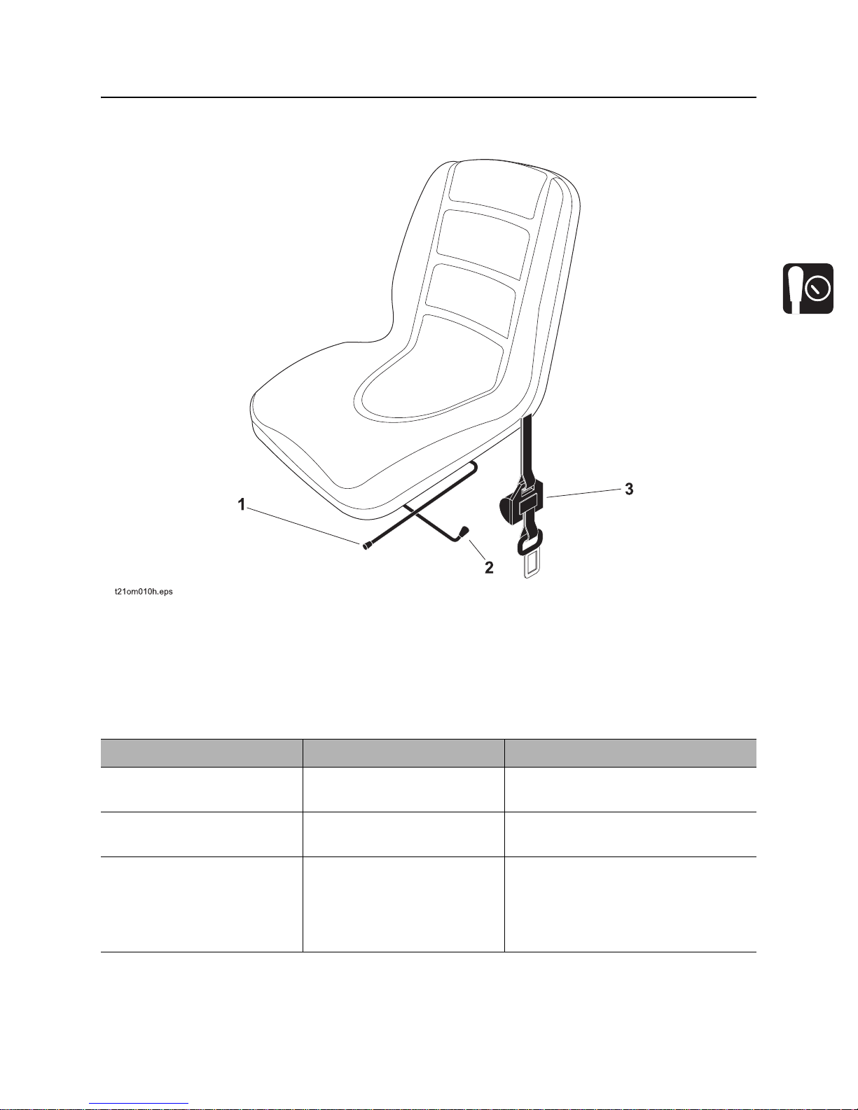
Seat
1. Seat Slide Control
2. Seat Swivel Control
Item Description Notes
1. Seat swivel control To slide seat, move control
away from seat.
2. Seat slide control To swivel seat, move control
toward back of seat.
3. Seat belt To fasten, insert latch into
buckle. Adjust until seat belt
is low and tight.
To release, lift top of buckle.
3. Seat Belt
CMW
Page 41
Controls - 40 HT220 Operator’s Manual
Top Console
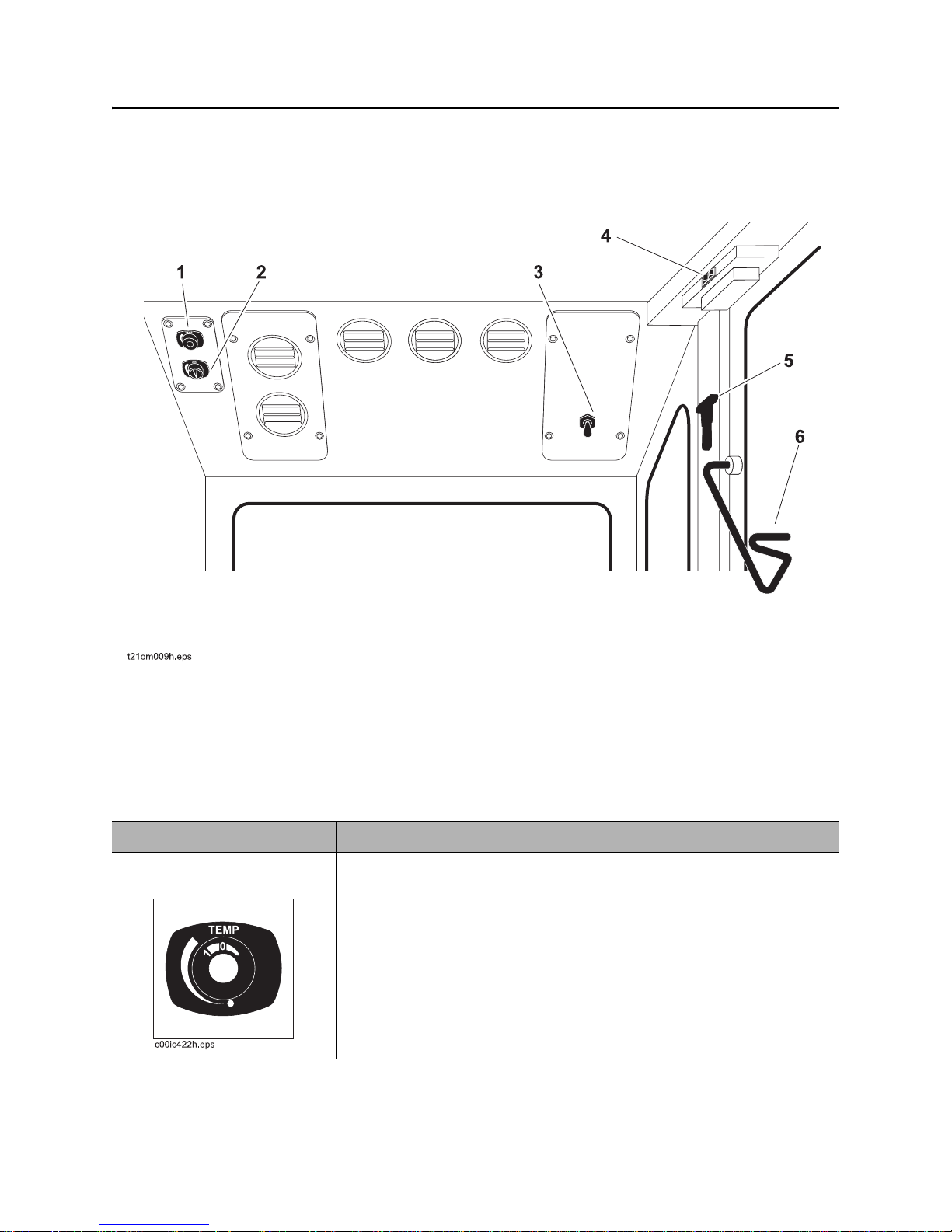
Top Console
1. Fan Power Control (three speed)
2. Air Conditioner Power Knob
3. Cab Pressurizer Switch
Item Description Notes
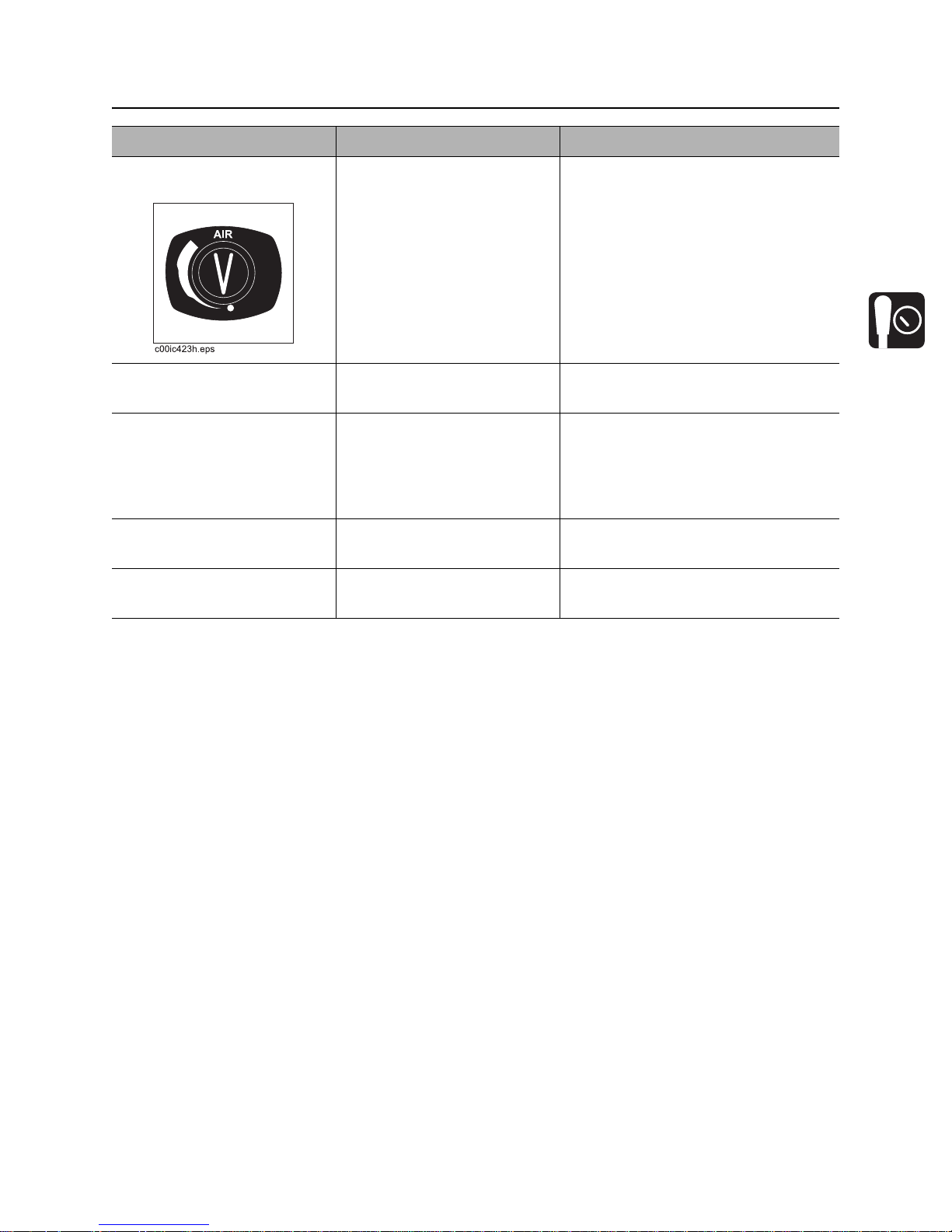
1. Air conditioner power
control
To adjust to desired cooling
intensity, turn control.
4. Cab Light Switch
5. Alternate Escape Method
6. Windshield Wiper Handle
Ensure that heater valves are turned
to the off position, See “Heater
Controls” on page 42.
CMW
Page 42
HT220 Operator’s Manual Controls - 41
Top Console
Item Description Notes
2. Ventilation (fan) power
control
3. Cab pressurizer switch To pressurize cab, press
4. Cab light switch To turn cab light on, turn
5. Alternate escape
method
6. Windshield wiper
handle
To adjust the rate of air flow,
turn control.
switch.
switch to the ON position.
To turn cab light off, turn
switch to the OFF position.
To escape cab in emergency,
use device to break glass.
To wipe windshield, move
lever.
CMW
Page 43
Controls - 42 HT220 Operator’s Manual
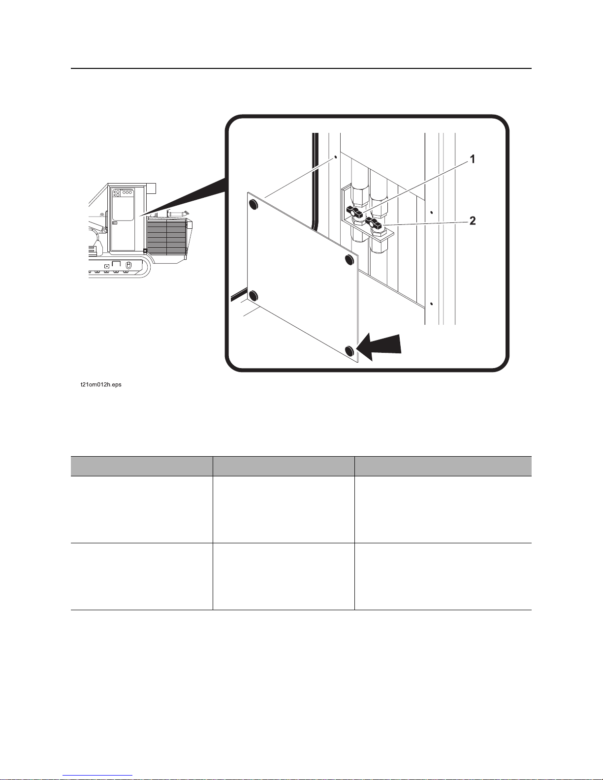
Heater Controls
Heater Controls
1. Coolant Return Valve 2. Coolant Delivery Valve
Item Description Notes
1. Coolant return valve To turn heater ON, turn valve
inline.
T o tur n heater OFF, turn valve
perpendicular.
2. Coolant delivery valve To turn heater ON, turn valve
inline.
T o tur n heater OFF, turn valve
perpendicular.
Ensure that air conditioner switch is in
the ‘OFF’ position before opening the
heater valves.
Ensure that air conditioner switch is in
the ‘OFF’ position before opening the
heater valves.
CMW
Page 44
HT220 Operator’s Manual Controls - 43
Battery Disconnects
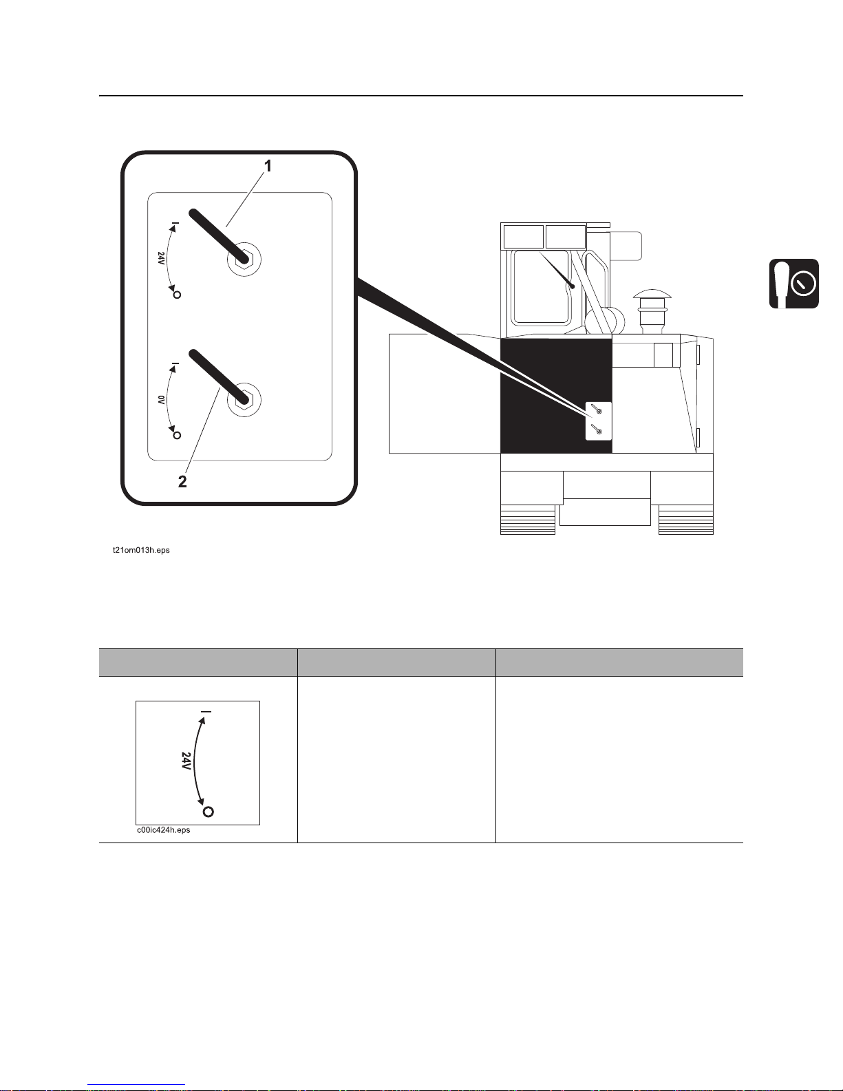
Battery Disconnects
1. Master disconnect (24V) 2. Master disconnect (0V)
Item Description Notes
1. Master Disconnect (0V) To connect the battery to the
electrical system, rotate
clockwise.
To disconnect the battery
from the electrical system,
rotate counterclockwise.
CMW
Page 45
Controls - 44 HT220 Operator’s Manual
Battery Disconnects
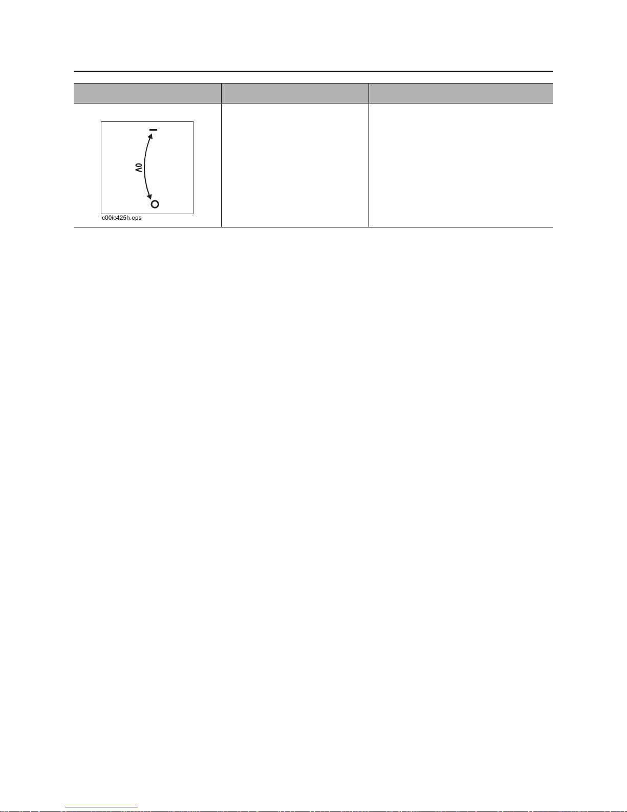
Item Description Notes
2. Circuit Breaker Lever To connect the battery to the
electrical system, rotate
clockwise.
To disconnect the battery
from the electrical system,
rotate counterclockwise.
CMW
Page 46
HT220 Operator’s Manual Controls - 45
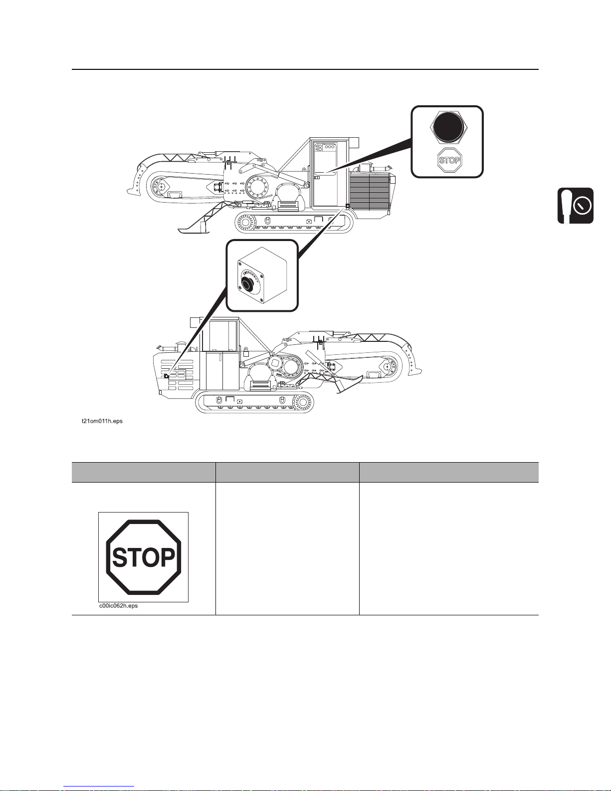
Emergency Stop
Emergency Stop
Item Description Notes
Emergency Engine Stop
Buttons
To stop machine immediately,
press button.
To release the stop function, the
button must be pulled “out” or twisted
clockwise to the “out” position. The
switches must be reset in order for the
engine to start.
Do not use emergency engine stop to
stop engine on a regular basis.
CMW
Page 47

Controls - 46 HT220 Operator’s Manual
Emergency Stop
CMW
Page 48

HT220 Operator’s Manual Prepare - 47
Prep are
Chapter Contents
Gather Information . . . . . . . . . . . . . . . . . . . . . . . . . 48
• Review Job Plan . . . . . . . . . . . . . . . . . . . . . . . . . . . . . . . . . . . . . . . . . . .48
• Notify One-Call Services. . . . . . . . . . . . . . . . . . . . . . . . . . . . . . . . . . . . .48
• Arrange for Traffic Control. . . . . . . . . . . . . . . . . . . . . . . . . . . . . . . . . . . .48
• Plan for Emergency Services . . . . . . . . . . . . . . . . . . . . . . . . . . . . . . . . .48
Inspect Site . . . . . . . . . . . . . . . . . . . . . . . . . . . . . . . 49
• Identify Hazards . . . . . . . . . . . . . . . . . . . . . . . . . . . . . . . . . . . . . . . . . . .49
Classify Jobsite. . . . . . . . . . . . . . . . . . . . . . . . . . . . 50
• Inspect Jobsite . . . . . . . . . . . . . . . . . . . . . . . . . . . . . . . . . . . . . . . . . . . .50
• Select a Classification. . . . . . . . . . . . . . . . . . . . . . . . . . . . . . . . . . . . . . .50
• Apply Precautions. . . . . . . . . . . . . . . . . . . . . . . . . . . . . . . . . . . . . . . . . .51
Check Supplies and Prepare Equipment . . . . . . . 52
• Supplies . . . . . . . . . . . . . . . . . . . . . . . . . . . . . . . . . . . . . . . . . . . . . . . . .52
• Fluid Levels. . . . . . . . . . . . . . . . . . . . . . . . . . . . . . . . . . . . . . . . . . . . . . .52
• Condition and Function. . . . . . . . . . . . . . . . . . . . . . . . . . . . . . . . . . . . . .52
• Accessories. . . . . . . . . . . . . . . . . . . . . . . . . . . . . . . . . . . . . . . . . . . . . . .52
CMW
Page 49

Prepare - 48 HT220 Operator’s Manual
Gather Information
Gather Information
A successful job begins before you dig. The first step in planning is reviewing info rmation already available
about the job and jobsite.
Review Job Plan
Review blueprints or other plans. Check for information about exi sting or planned stru ctures, elevations, or
proposed work that may be taking place at the same time.
Notify One-Call Services
Call area One-Call or similar services and have existing lines located and marked. Call any utilities in your
area that do not subscribe to One-Call.
Arrange for Traffic Control
If working near a road or other traffic area, contact local authorities about safety procedures and
regulations.
Plan for Emergency Services
Have the telephone numbers for local emergency and medical facilities on hand. Check that you will have
access to a telephone.
CMW
Page 50
HT220 Operator’s Manual Prepare - 49
Inspect Site
Inspect Site
Inspect jobsite before transporting equipment. Check for the following:
• changes in elevation such as hills or other open trenches
• obstacles such as buildings, railroad crossings, or streams
• signs of utilities (See “Inspect Jobsite” on page 50.)
•traffic
•access
• soil type and condition
Identify Hazards
Identify safety hazards and classify jobsite. See “Classify Jobsite” on page 50.
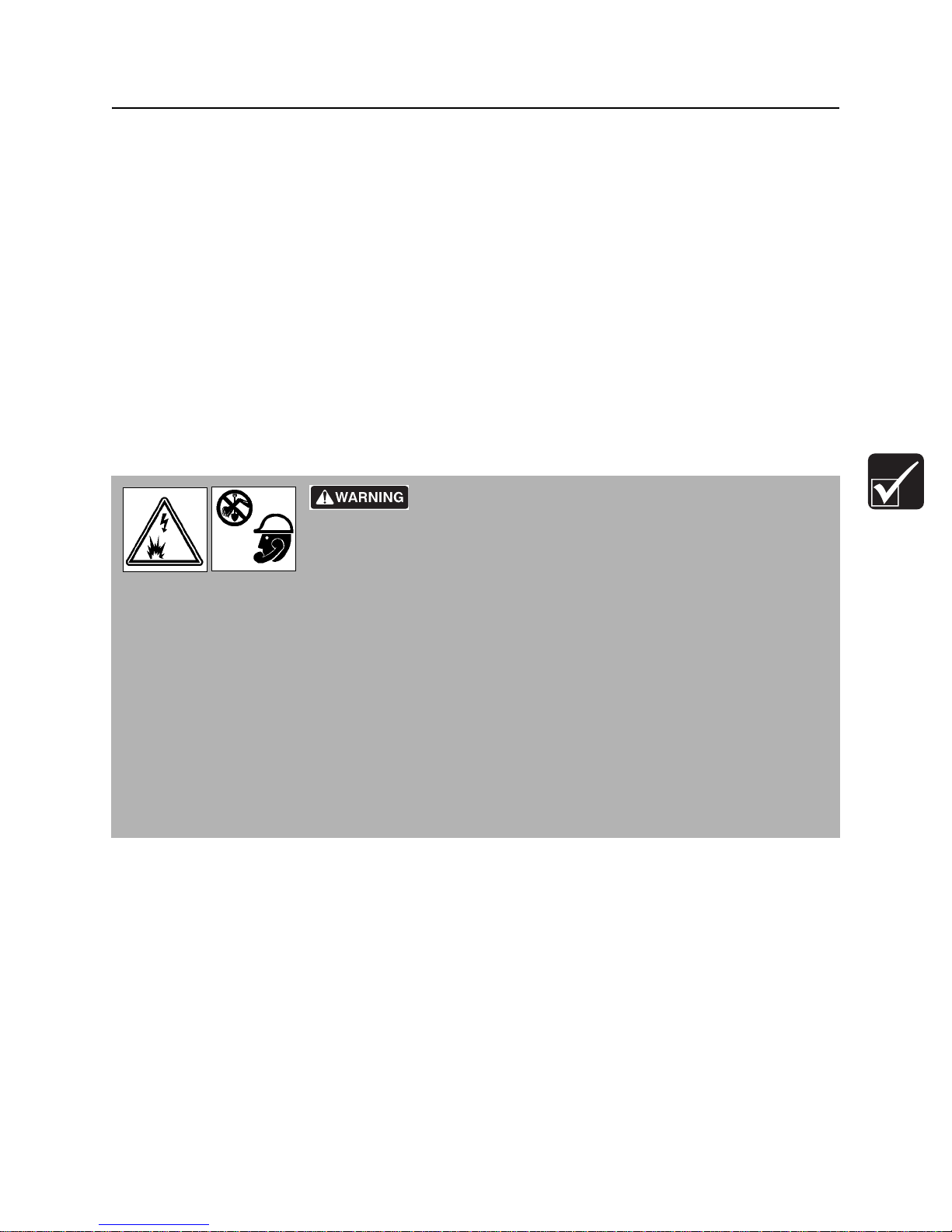
Jobsite hazards could cause death or serious injury. Use
correct equipment and work methods. Use and maintain proper safety
equipment.
NOTICE:
• Wear personal protective equipment including hard hat, safety eye wear, and hearing protection.
• Do not wear jewelry or loose clothing.
• Notify One-Call and companies which do not subscribe to One-Call.
• Comply with all utility notification regulations before digging or drilling.
• Verify location of previously marked underground hazards.
• Mark jobsite clearly and keep spectators away.
Remember, jobsite is classified by hazards in place -- not by line being installed.
CMW
Page 51

Prepare - 50 HT220 Operator’s Manual
Classify Jobsite
Classify Jobsite
Inspect Jobsite
• Follow U.S. Department of Labor regulations on excavating and trenching (Part 1926, Subpart P) and
other similar regulations.
• Contact your local One-Call service by dialing 811 (USA only) to have underground utilities located. A
One-Call referral number, 888-258-0808, is also available for both the USA and Canada. You should
also call any utility companies which do not participate in the One-Call service.
• Inspect jobsite and perimeter for evidence of underground hazards, such as:
– “buried utility” notices
– utility facilities without overhead lines
– gas or water meters
– junction boxes
– drop boxes
– light poles
– manhole covers
– sunken ground
• Have an experienced locating equipment operator sweep area within 20’ (6 m) to each side of trench
path. Verify previously marked line and cable locations.
• Mark location of all buried utilities and obstructions.
• Classify jobsite.
Select a Classification
Jobsites are classified according to underground hazards present.
If working . . . then classify jobsite as . . .
within 10’ (3 m) of a buried electric line electric
within 10’ (3 m) of a natural gas line natural gas
in sand, granite, or concrete which is capable of producing
crystalline silica (quartz) dust
within 10’ (3 m) of any other hazard other
NOTICE: If you have any doubt about jobsite classification, or if jobsite might contain unmarked
hazards, take steps outlined previously to identify hazards and classify jobsite before working.
crystalline silica (quartz) dust
CMW
Page 52

HT220 Operator’s Manual Prepare - 51
Classify Jobsite
Apply Precautions
Once classified, precautions appropriate for jobsite must be taken.
Electric Jobsite Precautions
Use one or both of these methods.
• Expose line by careful hand digging or soft excavation.
• Have service shut down while work is in progress. Have electric company test lines before returning
them to service.
Natural Gas Jobsite Precautions
In addition to positioning equipment upwind from gas lines, use one or both of these methods.
• Expose lines by careful hand digging or soft excavation.
• Have gas shut off while work is in progress. Have gas company test lines before returning them to
service.
Crystalline Silica (Quartz) Dust Precautions
Follow OSHA or other guidelines for exposure to crystalline silica when trenching, sawing or drilling
through material that might produce dust containing crystalline silica (quartz).
Other Jobsite Precautions
You may need to use different methods to safely avoid other underground hazards. Talk with those
knowledgeable about hazards present at each site to determine which precautions should be taken or if
job should be attempted.
CMW
Page 53

Prepare - 52 HT220 Operator’s Manual
Check Supplies and Prepare Equipment
Check Supplies and Prepare Equipment
Supplies
•fuel
•keys
• personal protective equipment, such as hard hat and safety glasses
• digging teeth
Fluid Levels
•fuel
• hydraulic fluid
•battery
• engine oil
• transmission fluid
Condition and Function
• digging chain and teeth
•fan belts
• light bulbs
• filters (air, oil, hydraulic)
•tracks
• pumps and motors
• hoses and valves
• signs, guards, and shields
Accessories
Fire Extinguisher
Check fire extinguisher charge regularly.
CMW
Page 54

HT220 Operator’s Manual Drive - 53
Drive
Chapter Contents
Start Unit . . . . . . . . . . . . . . . . . . . . . . . . . . . . . . . . . 54
Drive. . . . . . . . . . . . . . . . . . . . . . . . . . . . . . . . . . . . . 56
Shut Down. . . . . . . . . . . . . . . . . . . . . . . . . . . . . . . . 56
CMW
Page 55
Drive - 54 HT220 Operator’s Manual
Start Unit
Start Unit
Before operating tractor, read engine manufacturer’s starting and operating instructions. Follow
instructions for new engine break-in.
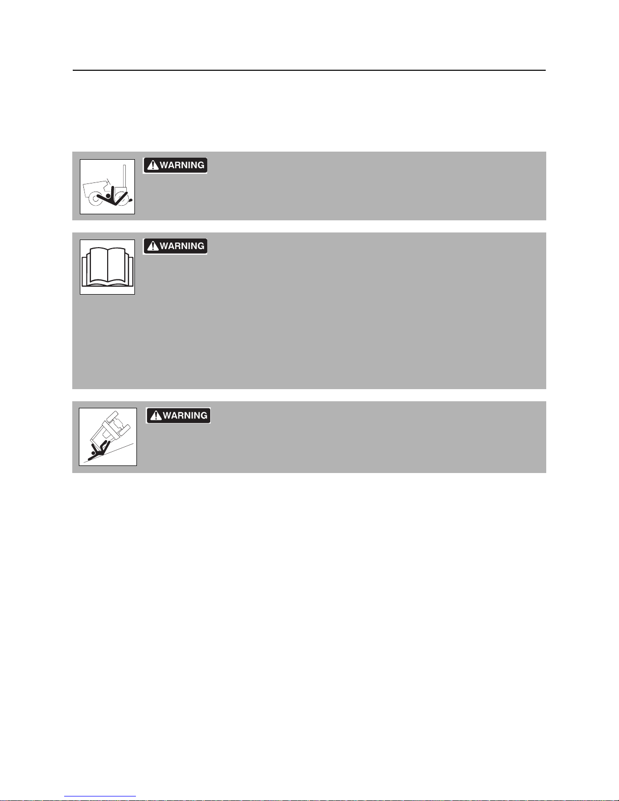
Runaway possible. Machine could run over you or others. Learn how to
use all controls. Start and operate only from operator’s position.
Incorrect procedures could result in death, injury, or property damage.
Learn to use equipment correctly.
NOTICE:
• Read operator’s manual before operating equipment. Follow instructions carefully. Contact your
Ditch Witch dealership for operation information or demonstration.
• Wear hard hat, safety glasses, and other protective eq uipm ent r equired by job. Do not wear jewelry
or loose clothing that can catch on controls.
Rollover possible. If machine rolls over, you could be thrown from seat
and killed or crushed. Wear seat belt.
1. Fasten and adjust seat belt.
2. Check that all controls are in neutral before starting.
3. Check that parking brake is engaged.
4. Move throttle to half open.
CMW
Page 56
HT220 Operator’s Manual Drive - 55
Start Unit
5. Turn ignition switch to the run position (key on, engine off). Cold start wait indicator will light.
NOTICE: If engine does not start within 20 seconds, release the ignition switch. Allow starter to cool
before attempting to start the unit again.
6. When cold start wait indicator goes off, turn ignition switch all the way clockwise to start tractor.
Warning alarm will sound. Indicators will light.
• If engine does not crank, check battery disconnect. See page 43 for battery disconnect
information.
• If engine turns but does not start within 20 seconds, allow starter to cool before trying to start
again.
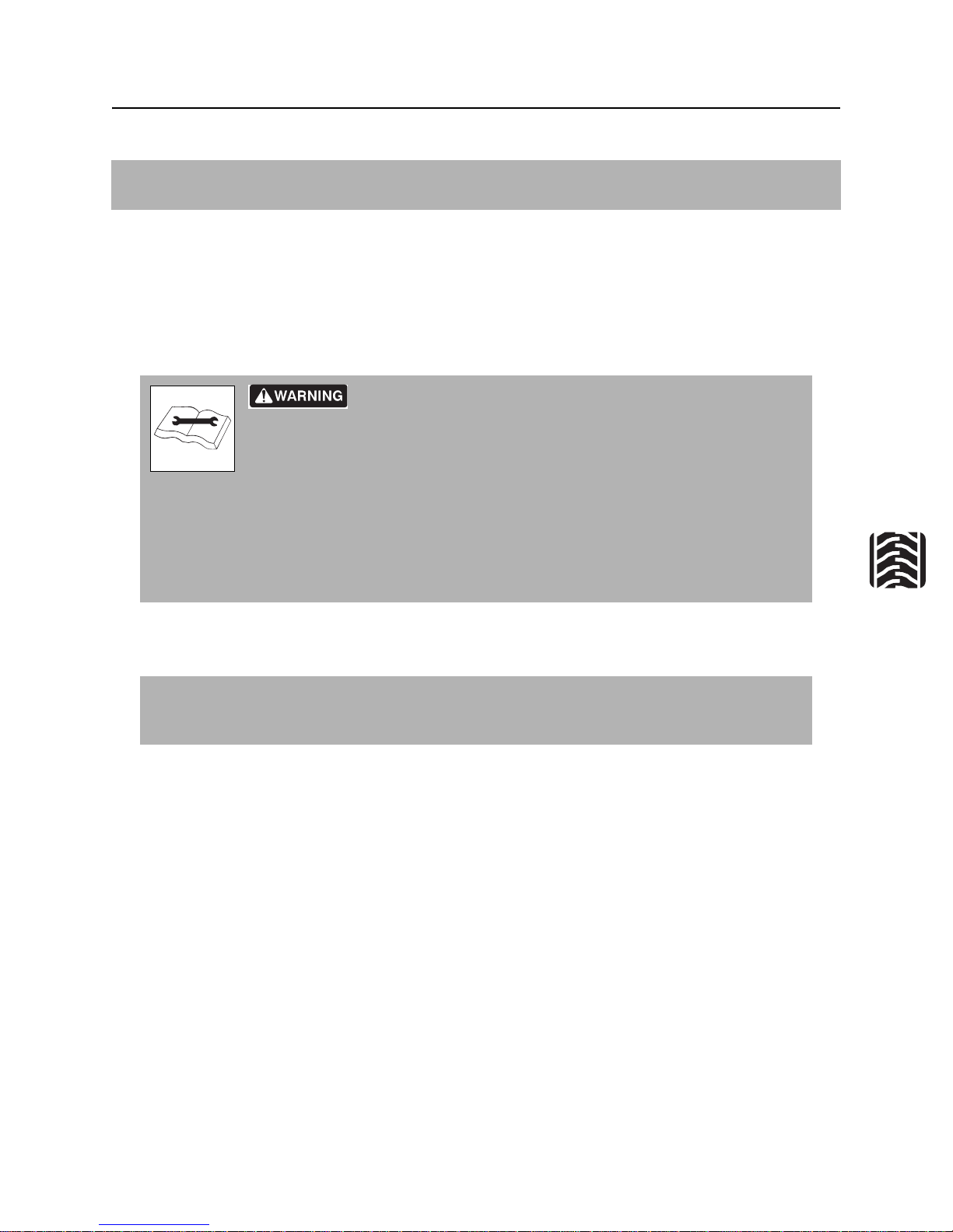
Improper control function could cause death or serious injury. If
control does not work as described in instructions, stop machine and have it
serviced.
NOTICE:
• If warning alarm does not sound, have machine repaired.
• Machine will not start if start batteries are disconnected. See page 43 for battery disconnect
information.
7. Run engine at half-throttle or less for five minutes before operating tractor. Du ring warm-up, check that
all controls work properly.
IMPORTANT: Some operations will not function if any controls are not in the neutral position
upon start up. If some functions do not work, turn ignition key to th e off position and ensure that
all controls are in the neutral position.
CMW
Page 57

Drive - 56 HT220 Operator’s Manual
Drive
Drive
EMERGENCY SHUTDOWN: Press the emergency stop button to stop.
1. Verify that parking brake is disengaged.
2. Adjust throttle to about half way.
3. Adjust boom lift switch to raise boom.
4. Adjust the direction control lever to move unit forward or backward.
5. Adjust steering control lever to adjust the direction.
6. Change engine speed with throttle.
Moving traffic – hazardous situation. Death or serious injury could result.
Avoid moving vehicles, wear high visibility clothing, post appropriate warning signs.
NOTICE:
• Drive carefully in congested areas. Know machine’s clearance and turning radius.
• Keep attachments low when operating on slope. Drive slowly and cautiously.
Shut Down
1. Move direction control levers to the neutral position.
2. Lower boom to ground.
3. Engage parking brake.
4. Reduce engine speed to a minimum.
5. Wait five minutes for engine to cool down.
6. Turn ignition switch to STOP.
7. Turn off the air conditioner and the lights, if on.
8. If leaving the machine unattended, remove key and lock the following: cab window, door, engine
compartment doors, tool compartment door and the tank locking caps.
CMW
Page 58

HT220 Operator’s Manual Drive - 57
Start After Emergency Stop
Start After Emergency Stop
1. Turn all panel controls in use at the moment of the emergency stop to the neutral position.
2. Turn the emergency stop push-button counterclockwise.
3. Turn the key to the start position.
4. Start the machine by following the standard procedure. See “Start Unit” on page 54..
CMW
Page 59

Drive - 58 HT220 Operator’s Manual
Start After Emergency Stop
CMW
Page 60

HT220 Operator’s Manual Transport - 59
Transport
Chapter Contents
Lift . . . . . . . . . . . . . . . . . . . . . . . . . . . . . . . . . . . . . . 60
• Points . . . . . . . . . . . . . . . . . . . . . . . . . . . . . . . . . . . . . . . . . . . . . . . . . . .60
• Procedure . . . . . . . . . . . . . . . . . . . . . . . . . . . . . . . . . . . . . . . . . . . . . . . .61
Tie Down . . . . . . . . . . . . . . . . . . . . . . . . . . . . . . . . . 62
• Points . . . . . . . . . . . . . . . . . . . . . . . . . . . . . . . . . . . . . . . . . . . . . . . . . . .62
• Procedure . . . . . . . . . . . . . . . . . . . . . . . . . . . . . . . . . . . . . . . . . . . . . . . .62
Haul . . . . . . . . . . . . . . . . . . . . . . . . . . . . . . . . . . . . . 63
• Procedure . . . . . . . . . . . . . . . . . . . . . . . . . . . . . . . . . . . . . . . . . . . . . . . .63
Tow . . . . . . . . . . . . . . . . . . . . . . . . . . . . . . . . . . . . . 65
• Procedure . . . . . . . . . . . . . . . . . . . . . . . . . . . . . . . . . . . . . . . . . . . . . . . .65
CMW
Page 61
Transport - 60 HT220 Operator’s Manual
Lift
Lift
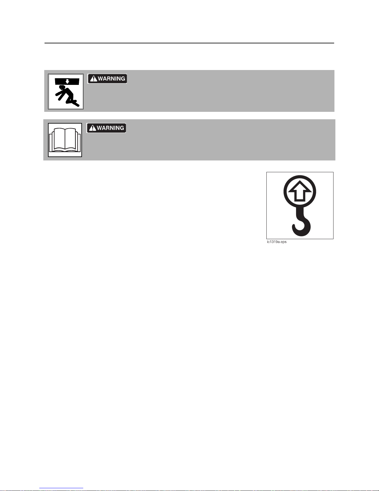
Crushing weight. If load falls or moves it could kill or crush you. Use
proper procedures and equipment or stay away.
Incorrect procedures could result in death, injury, or property damage.
Learn to use equipment correctly.
Points
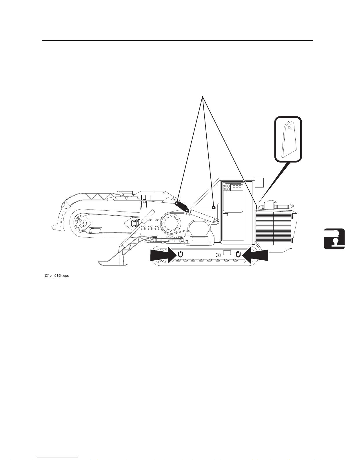
Lifting points are identified by lifting decals. Lifting at other points is unsafe
and can damage machinery.
CMW
Page 62
HT220 Operator’s Manual Transport - 61
Lift
Procedure
Tractor
Use a crane capable of supporting the equipment's size and weight. See “Specifications” on page 135.
Use indicated lift points (shown).
CMW
Page 63
Transport - 62 HT220 Operator’s Manual
Tie Do wn
Tie Down
Incorrect procedures could result in death, injury, or property damage.
Learn to use equipment correctly.
Points
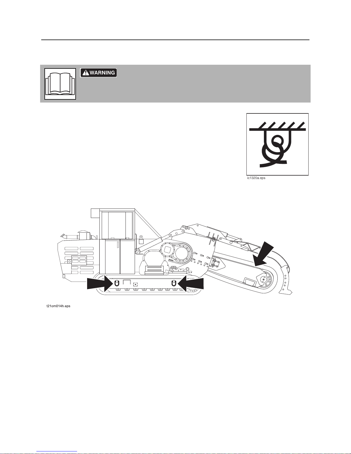
tie-down points are identified by tiedown decals. Securing to trailer at other
points is unsafe and can damage machinery.
Procedure
Attach chains at front and rear tiedown points. Make sure chains are tight before transporting unit. Lower
boom and tie down.
CMW
Page 64
HT220 Operator’s Manual Transport - 63
Haul
Haul
Incorrect procedures could result in death, injury, or property damage.
Learn to use equipment correctly.
NOTICE:
• Read trailer operator’s manual before loading or transporting your machine. Incorrectly loaded
machine can slip or cause trailer sway.
• Attach trailer to tow vehicle before loading or unloading.
• Park, load, and unload trailer on level ground.
• Check that unit and trailer do not exceed size or weight regulations.
• Ensure that tow vehicle has proper tow capacity rating.
Procedure
Refer to trailer owner’s manual and local and regional laws for correct hauling procedures.
Load
Crushing weight. If load falls or moves it could kill or crush you. Use
proper procedures and equipment or stay away.
NOTICE:
• Attach trailer to tow vehicle before loading or unloading.
• Load and unload trailer on level ground.
• Put manual transmission into first or reverse gear or automatic transmission into park. Turn off
ignition. Set parking brake.
• Block trailer wheels.
• Incorrect loading can cause trailer swaying.
and killed or crushed. Wear seat belt.
Rollover possible. If machine rolls over, you could be thrown from seat
CMW
Page 65
Transport - 64 HT220 Operator’s Manual
Haul
1. Fasten and adjust seat belt.
2. Start tractor. See page 56 for proper start-up procedures.
3. Raise trenching boom, but keep it low.
4. Release parking brake.
5. Use speed/direction control to slowly drive unit onto trailer until tiedown position is reached.
6. Engage parking brake.
7. Lower attachments to trailer bed and turn tractor off. See page 56 for proper shutdown procedures.
8. Attach chains to tractor and attachments where tiedown decals are located. See page 62.
Unload
Crushing weight. If load falls or moves it could kill or crush you. Use
proper procedures and equipment or stay away.
NOTICE:
• Attach trailer to tow vehicle before loading or unloading.
• Load and unload trailer on level ground.
• Put manual transmission into first or reverse gear or automatic transmission into park. Turn off
ignition. Set parking brake.
• Block trailer wheels.
• Incorrect loading can cause trailer swaying.
Rollover possible. If machine rolls over, you could be thrown from seat
and killed or crushed. Wear seat belt.
1. Lower trailer or ramps.
2. Remove chains from tiedowns.
3. Fasten and adjust seat belt.
4. Start tractor. See page 54 for proper start-up procedures.
5. Raise trencher boom, but keep it low.
6. Disengage parking brake.
7. Use speed/direction control to slowly back unit down trailer or ramps.
CMW
Page 66
HT220 Operator’s Manual Transport - 65
Tow
Tow
Incorrect procedures could result in death, injury, or property damage.
Learn to use equipment correctly.
Under normal conditions, tractor should not be towed. If tractor becomes disabled and towing is
necessary:
• Do not tow for more than 200 yd (180 m).
• Tow at less than 3 mph (4.8 km/h).
• Use maximum towing force of 1.5 times unit weight.
Procedure
Learn to use equipment correctly.
Connect Tow Cables
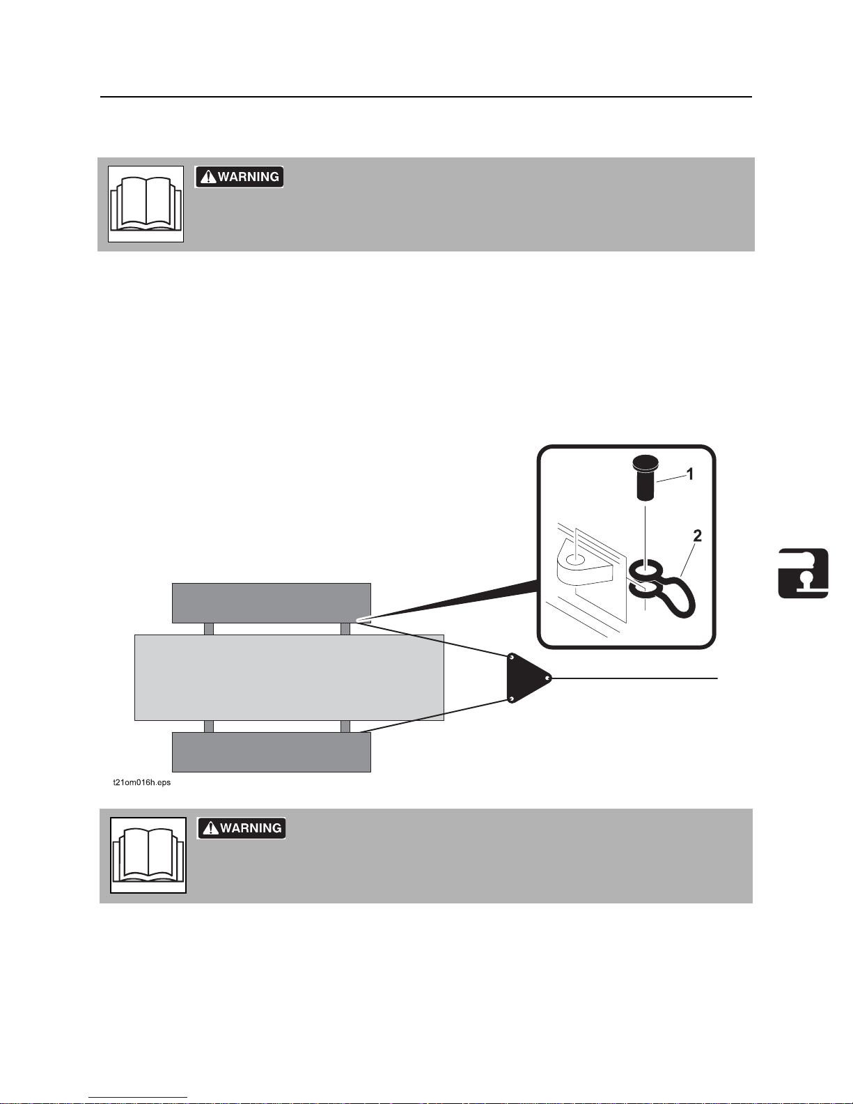
1. Connect the tow cables or chains to the eyes on the front of the undercarriage.
2. Clevis pins (1,2) may be added to the eyes to aid in the lining up of cables or chains.
Incorrect procedures could result in death, injury, or property damage.
CMW
Page 67

Transport - 66 HT220 Operator’s Manual
Tow
3. Wrap a chain or cable around the boom, chain and baseplates.
4. Hook one unit to tow in the front, and another in the back to aid in braking. Avoid towing over long
distances. Do not exceed 3 mph (4.8 km/hr).
Disconnect Brakes
1. Block tracks to immobilize unit.
2. Disconnect the hydraulic brake hoses and cap the valve to keep contaminants out.
3. Connect a tee between the two disconnected hoses to provide equal pressur e to each gearbox.
4. Connect a hand pump containing hydraulic fluid to the tee.
5. Pump to 500 psi but do not exceed 500 psi. This will release the brake.
Remove Ground Drive Motors
1. Remove the ground drive motor plates and unbolt the ground drive motor. Do not remove the hydraulic
hoses. Support the motors by placing them on the lower support or by tying them up. Do not let them
drag on the ground.
2. Tow machine slowly.
3. When towing is complete, reattach the brake line and motors so that the machine will not move after
disconnecting.
CMW
Page 68

HT220 Operator’s Manual Trench - 67
Trench
Chapter Contents
Setup . . . . . . . . . . . . . . . . . . . . . . . . . . . . . . . . . . . . 68
Operation. . . . . . . . . . . . . . . . . . . . . . . . . . . . . . . . . 69
Operating Tips . . . . . . . . . . . . . . . . . . . . . . . . . . . . 71
• Trenching . . . . . . . . . . . . . . . . . . . . . . . . . . . . . . . . . . . . . . . . . . . . . . . .71
CMW
Page 69
Trench - 68 HT220 Operator’s Manual
Setup
Setup
EMERGENCY SHUTDOWN: Press the emergency stop button to stop.
Crushing weight could cause death or serious injury. Use proper
procedures and equipment or stay away.
Jobsite hazards could cause death or serious injury. Use
correct equipment and work methods. Use and maintain proper safety
equipment.
NOTICE: Comply with all utility notification regulations before digging or drilling.
Incorrect procedures can result in death, injury, or property damage.
Learn to use equipment correctly.
1. Fasten and adjust seat belt.
2. Start tractor. See page 48 for start-up procedures.
3. Drive to starting point. Move in line with planned trench.
4. Push throttle to low.
5. Lower boom to just above ground.
6. Engage parking brake.
CMW
Page 70
HT220 Operator’s Manual Trench - 69
Operation
Operation
Jobsite hazards could cause death or seriou s injury. Use correct
equipment and work methods. Use and maintain proper safety equipment.
NOTICE: Cutting or drilling concrete containing sand or rock containing quartz may result in exposure to
silica dust. Use respirator, water spray or other means to control dust. Silica dust can cause lung
disease and is known to the State of California to cause cancer.
Electrical shock. Contacting electrical lines will cause death or serious
injury . Know location of lines and stay away.
NOTICE: Cutting high voltage cable can cause electrocu tion. Expose lines by hand befo re
digging.
Incorrect procedures could result in death, injury, or property damage.
Learn to use equipment correctly.
NOTICE:
• Comply with all utility notification regulations before digging or drilling.
• Notify companies that do not subscribe to One-Call.
Flying objects thrown by machine may strike people. Wear hard hat and
safety glasses.
Moving digging teeth will cause death or serious injury. Stay away.
NOTICE:
• Ensure parking brake is engaged.
• Machine might jerk when digging starts. Allow 3’ (1 m) between digging teeth and obstacle.
• Keep everyone at least 15’ (5 m) from machine, at tachments, and thei r ra ng e of mov eme nt .
CMW
Page 71

Trench - 70 HT220 Operator’s Manual
Operation
1. Select the desired direction and position for conveyors to run and operate them at a moderate speed.
2. Lift the trench cleaner completely.
IMPORTANT: The only function of the trench cleaner is keeping the trench bottom clean. It must
not be used for pushing or pulling anything. Make sure it does not get caught in the trench for any
reason and the shoe is free to slide on its support.
3. Place the chain operation control in the forward direction (or digging direction) at the desired speed.
4. Slowly lower the digging boom taking care not to stall the digging chain.
5. Release the parking brake.
6. Adjust the direction control lever to move the machine forward.
7. Ensure that the pressure values on the chain and track circuit pressure gauges do not exceed the
maximum values. See “Gauges” on page 31.
8. After digging enough space for the trench cleaner, lower it.
Note: When digging on slopes, it might be necessary to set the parking brake until the trencher
reaches the desired digging depth. Under such circumstances, release the parking brake before
operating the direction control.
CMW
Page 72

HT220 Operator’s Manual Trench - 71
Operating Tips
Operating Tips
Trenching
• Operate engine at full throttle under load for most productive trenching. If soil conditions permit,
operating in this range gives longer engine life and more efficient use of available engine power.
• A shorter turn may be made with the digging boom at full depth. Take care to prevent excessive side
load.
• If an object becomes lodged in the digging chain:
• Move speed/direction control to neutral.
• Raise boom slightly to clear bottom of trench.
• Move transmission lever to reverse.
• Chain should reverse and release object.
• When cutting across asphalt roads, start trench in soil at the edge of the road and dig trench with
shortest possible boom at full depth.
CMW
Page 73

Trench - 72 HT220 Operator’s Manual
Operating Tips
CMW
Page 74

HT220 Operator’s Manual Systems and Equipment - 73
Systems and Equipment
Chapter Contents
Chain, Teeth, and Sprockets . . . . . . . . . . . . . . . . . 74
• Chain and Tooth Maintenance . . . . . . . . . . . . . . . . . . . . . . . . . . . . . . . .74
• Chain Types . . . . . . . . . . . . . . . . . . . . . . . . . . . . . . . . . . . . . . . . . . . . . .74
• Chain Selection. . . . . . . . . . . . . . . . . . . . . . . . . . . . . . . . . . . . . . . . . . . .75
Optional Equipment . . . . . . . . . . . . . . . . . . . . . . . . 76
• Tractor. . . . . . . . . . . . . . . . . . . . . . . . . . . . . . . . . . . . . . . . . . . . . . . . . . .76
• Trencher . . . . . . . . . . . . . . . . . . . . . . . . . . . . . . . . . . . . . . . . . . . . . . . . .76
Diagnostics . . . . . . . . . . . . . . . . . . . . . . . . . . . . . . . 77
• Display of Failure . . . . . . . . . . . . . . . . . . . . . . . . . . . . . . . . . . . . . . . . . .77
• Reading Error Messages . . . . . . . . . . . . . . . . . . . . . . . . . . . . . . . . . . . .77
• Error Message List . . . . . . . . . . . . . . . . . . . . . . . . . . . . . . . . . . . . . . . . .77
• Engine Failure Code List. . . . . . . . . . . . . . . . . . . . . . . . . . . . . . . . . . . . .80
• Determining Error Codes . . . . . . . . . . . . . . . . . . . . . . . . . . . . . . . . . . . .88
• Irregular Functions . . . . . . . . . . . . . . . . . . . . . . . . . . . . . . . . . . . . . . . . .90
Page 75

Systems and Equipment - 74 HT220 Operator’s Manual
Chain, Teeth, and Sprockets
Chain, Teeth, and Sprockets
Chain and Tooth Maintenance
• Always replace sprockets at the same time you replace the digging chain. Sprockets and chain are
designed to work together. Replacing one without the other will cause premature wear of the new part.
• Keep digging teeth sharp. Using dull, worn teeth will decrease production and increase shock load to
other trencher components. It can also cause chain stretch, which leads to premature chain wear and
failure.
• Maintain the proper amount of tension on the digging chain. Overtightening will cause chain stretch
and loss of machine performance. For correct tightening procedure, see page 112.
• Use the tooth pattern most appropriate for your digging conditions. If you move to a different soil type,
contact your Ditch Witch dealer for information about the most effective chain type and tooth pattern.
Chain Types
Chain type Features
4-pitch standard chain
2-pitch more teeth for smoother cuttin g
alternating side bar prevents spoil compaction on chain
bolt-on adapters allow easy configuration changes
Shark Chain II versatile, virtually maintenance-fr ee
combination provides pick and shovel effect
Page 76
HT220 Operator’s Manual Systems and Equipment - 75
Chain, Teeth, and Sprockets
Chain Selection
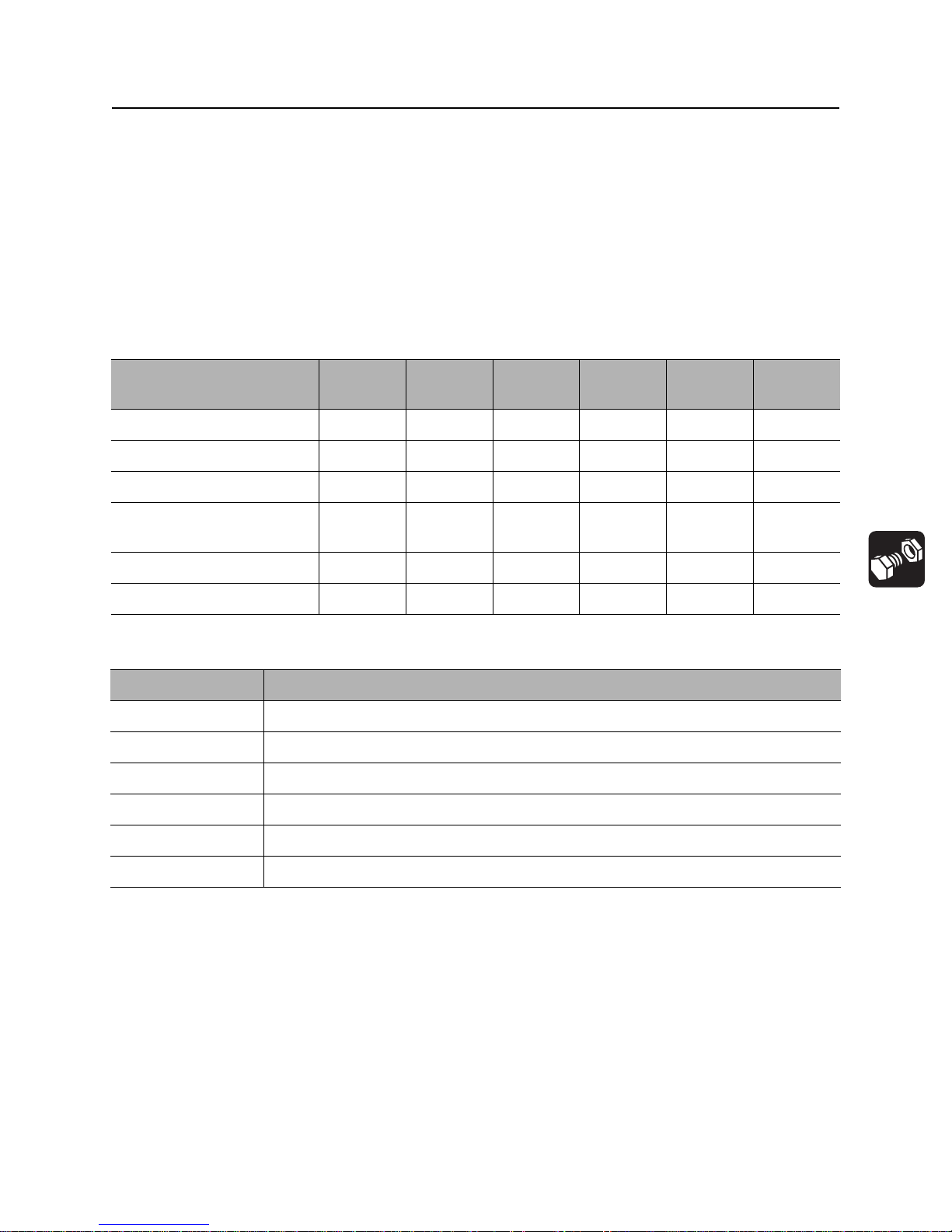
These charts are meant as a guideline only. No one chain type works well in all conditions. See your Ditch
Witch dealer for soil conditions and chain recommendations for your area. Ask for the latest Chain, Teeth,
and Sprockets Parts Catalog.
• 1 = best
• 2 = better
• 3 = good
• 4 = not recommended
Chain Sandy
Soil
4-pitch cup tooth 3 1 2 3 4 1
2-pitch cup tooth 2 3 1 1 3 4
bolt-on adaptor, 2-pitch 4 4 3 2 1 4
bolt-on adaptor/cup tooth
combo
Shark Chain II 432114
alternating side bar 4 4 4 4 4 1
Soil Description
sandy soil sugar sand, blow sand, or other soils where sand is the predominant component
soft soil sandy loam
medium soil loams, loamy clays
hard soil packed clays, gumbo, all compacted soils
432124
Soft Soil Medium
Soil
Hard Soil Rocky
Soil
Sticky
Soil
rocky soil chunk rock, glacial till, cobble, rip rap, gravel
sticky soil gumbo, sticky clays
Page 77

Systems and Equipment - 76 HT220 Operator’s Manual
Optional Equipment
Optional Equipment
See your Ditch Witch dealer for more information about the following optional equipment.
Tractor
Equipment Description
light kit p/n 215-1191
window cover kit p/n 190-1174
Trencher
Equipment Description
truck conveyor p/n 140-1081
carbide bit p/n 135-1015
spade bit p/n 135-1016
trench cleaners
restraint bar p/n 140-1073
4’, 6’ (1.2, 1.8 m) depth p/n 140-1074
8’ (2.4 m) depth p/n 140-1075
4’ (1.2 m) double chain p/n 140-1069
6’ (1.8 m) double chain p/n 140-1071
truck conveyor p/n 140-1081
trench cleaner shoes
shoe cleaner (12”) p/n 140-1076
shoe cleaner (14”) p/n 140-1077
shoe cleaner (16”) p/n 140-1078
shoe cleaner (18”) p/n 140-1079
shoe cleaner (24”) p/n 140-1080
Page 78

HT220 Operator’s Manual Systems and Equipment - 77
Diagnostics
Diagnostics
Display of Failure
The red error warning light signals the presence of a possible failure.
Reading Error Messages
Press <F3> on the BB3 diagnostic instrument. The latest error is shown on the upper corner of the display.
If there are no messages, then “No errors” will be displayed. To go back to the main menu, press the
<ESC> key.
Error Message List
Error
Message
List
Sol. Lft. Forw Short circuit/
Sol. Lft.
Backw
Sol. Rgt.
Forw
Sol. Rgt.
Backw
Failure Type Function Affect ed Error
interrupted cable or
solenoid
Short circuit/
interrupted cable or
solenoid
Short circuit/
interrupted cable or
solenoid
Short circuit/
interrupted cable or
solenoid
Left track pump
solenoid forward
Left track pump
solenoid backward
Right track pump
solenoid forward
Right track pump
solenoid backward
Effect
Warning
Light
Yes The forward drive is blocked.
The brakes are set. (Reset by
positioning the steering and
direction levers in central
position)
Y es The backward drive is blocked.
The brakes are set. (Reset by
positioning the steering and
direction levers in central
position)
Yes The forward drive is blocked.
The brakes are set. (Reset by
positioning the steering and
direction levers in central
position)
Y es The backward drive is blocked.
The brakes are set. (Reset by
positioning the steering and
direction levers in central
position)
Sol. Motor
Lft.
Short circuit/
interrupted cable or
solenoid
Left track motor
solenoid
Yes Slow speed selected. Drive
and digging possible. (Reset
by positioning the steering and
direction levers in central
position)
Page 79

Systems and Equipment - 78 HT220 Operator’s Manual
Diagnostics
Error
Message
List
Sol. Motor
Rgt
Sol. chain
forw
Sol. chain
backw
Steer. Pot.
joys
Driv. Pot.
Joys
Failure Type Function Affect ed Error
Warning
Light
Short circuit/
interrupted cable or
solenoid
Short circuit/
interrupted cable or
solenoid
Short circuit/
interrupted cable or
solenoid
Short circuit/
interrupted cable or
potentiometer
short circuit /
interrupted cable or
potentiometer
Chain pump solenoid
forward
Chain pump solenoid
forward
Chain pump solenoid
backward
Steering lever
potentiometer
Direction lever
potentiometer
Y es Slow speed inserted Drive and
Y es Forward chain rotation locked.
Yes Backward chain rotation
Yes Drive locked. The brakes are
Yes Drive locked. The brakes are
Effect
digging possible. (Reset by
positioning the steering and
direction levers in central
position)
(Reset by positioning the chain
lever in central position)
locked. (Reset by positioning
the chain lever in central
position)
inserted (Reset by positioning
the steering and direction
levers in central position)
inserted (Reset by positioning
the steering and direction
levers in central position)
Driving Sw. Both selectors ‘on’ /
Both selectors ‘off’
with the lever not in
zero position
Steering Sw. Both selectors ‘on’ /
Both selectors ‘off’
with the lever not in
zero position
Chain Pot.
Joyst
Chain Sw. Both selectors ‘on’ /
Sensitiv.
Press.
Short circuit/
interrupted cable or
potentiometer
both selectors ‘off’
with the lever not in
zero position
Short circuit /
interrupted cable or
potentiometer
Direction lever
selectors
Steering lever
selectors
Chain lever
potentiometer
Chain lever selectors Yes Chain rotation is locked.
‘Automatic steering
sensitivity’
potentiometer
Yes Drive locked. The brakes are
inserted. (Reset by positioning
the steering and direction
levers in central position)
Yes Drive locked. The brakes are
inserted. (Reset by positioning
the steering and direction
levers in central position)
Yes Chain rotation locked. (Reset
by positioning the chain lever
in central position)
(Reset by positioning the chain
lever in central position)
Y es Automatic steering set on 300
bar pressure. (Reset by
positioning the chain lever in
central position)
Page 80

HT220 Operator’s Manual Systems and Equipment - 79
Diagnostics
Error
Message
List
Fine Steer.
Pot.
Fine Steer.
Off
Engine
Speed
Mot Speed
Right
Failure Type Function Affect ed Error
Warning
Light
Short circuit /
interrupted cable or
potentiometer
Short circuit /
interrupted cable or
potentiometer
Diesel engine off /
short circuit - cable
or sensor
interrupted / sensor
out-of-adjustment
+24V failure / short
circuit - cable or
sensor interrupted /
sensor out-ofadjustment
‘Fine steering’
potentiometer
‘Fine steering’
potentiometer
Diesel speed sensor Yes Engine load control system
Speed sensor of rig ht
track motor speed
Y es Drive locked. After bringin g the
Yes System for straight running
Effect
direction lever back to centre:
the warning light blinks; driving
is possible; the potentiometer
is cut off. (Reset by positioning
the steering and direction
levers in central position)
This message appears to
indicate the cutting off of the
fine steering potentiometer
after a failure and the ensuing
reset (See previous point)
disconnected Driving and
digging possible. (Reset by
positioning the steering and
direction levers in central
position)
control disconnected. Driving
and digging possible (Reset
when the signal is OK)
Mot Speed
Left
Standard
condition
Master/
Slave int
Low Voltage <24 Volt current: Battery or generator
Parking
brake
+24V failure / short
circuit - cable or
sensor interrupted /
sensor out-ofadjustment
On panel switching
on, direction or
steering or chain
lever not centered
A52 or B52
interrupted. Internal
connection to
Microcontroller
faulty
Selector open or
cable interrupted
Speed sensor of left
track motor speed
Condition of levers
centered from start
failure
Brake selector
inserted.
Yes System for straight running
control disconnected. Driving
and digging possible (Reset
when the signal is OK)
Y es Chain and track drives locked.
(Reset by repositioning all
levers in central position)
Check that the A52 cable is
connected to ground and that
the B52 cable is connected to
+24. Replace the
Microcontroller.
No Error displayed on BB3 only.
Yes Driving blocked. Brakes
inserted.
Page 81

Systems and Equipment - 80 HT220 Operator’s Manual
Diagnostics
Error
Message
List
Seat Switch Operator not
Oil Press.
Eng.
Temperat.
Eng.
Oil Level
Hydrau
Suction
Pressure
Failure Type Function Affect ed Error
seated / seat switch
faulty or cable
interrupted
Engine oil pressure
insufficient / cable
or sensor short
circuit
Engine water
overheating / cable
or sensor short
circuit
Hydraulic oil level
low / cable or
sensor short circuit
Cock proximity
sensors faulty /
cocks closed /
cable short circuit
Effect
Warning
Light
Seat switch open Yes The diesel engine stalls in 5
seconds. The starter does not
run.
Diesel engine oil
pressure gauge
Diesel engine coolant
thermocouple
Hydraulic oil level
float
Hydraulic circuit
cocks
Yes The diesel engine stalls in 10
seconds.
Yes Hydraulic drives
disconnected. If this lasts for
more than 20 seconds, the
diesel engine stalls. The
starter does not run.
Yes The diesel engine stalls in 10
seconds.
Yes The diesel engine stalls. The
starter does not run.
Time Limit
Rental
Bus Error Signal interruption
Rental scheduled
time expired
Display can-bus
Digging chain drive Yes Digging chain drive
No signalling on
display
Engine Failure Code List
Failure Code
Warning
Light
111 Yellow Internal error of the controller
115 Yellow No positio ning sign al or en gine r pm
122 Yellow High voltage from the turbo pressure
Cause Effect (only when the failure code is active)
hardware
signal has been detected.
sensor signal has been detected on
pin 45 of the engine connector
disconnected. (Reset by
bringing the chain lever back in
central position and insert a
new time limit via the BB3)
Check FUS13, resistor RR1
and connections A26 - A27
Probably no effect or irregular working or engine
ignition failure.
Reduced engine output or white smoke.
The engine output will be reduced to a nonsupercharging rpm.
Page 82

HT220 Operator’s Manual Systems and Equipment - 81
Diagnostics
Failure Code
Warning
Light
123 Y ellow Low voltage from the turbo pressure
131 Y ellow Low voltage from the turbo pressure
132 Yellow Low voltage from the accelerator
133 Yellow High voltage on the accelerator
134 Yellow Low voltage on the accelerator
135 Yellow High voltage from the oil pressure
Cause Effect (only when the failure code is active)
sensor signal has been detected on
pin 45 of the engine connector
sensor signal has been detected on
pin 45 of the engine connector
position signal has been detected on
pin 30 of the OEM connector.
signal has been detected. Remote
on pin 9 of the OEM connector.
signal has been detected. Remote
on pin 9 of the OEM connector.
sensor signal has been detected on
pin 33 of the engine connector.
The engine output will be reduced to a nonsupercharging rpm.
The engine will remain idle when the pedal is
released; the engine will keep a stable rpm when
the accelerator is pressed.
The engine will remain idle when the pedal is
released; the engine will keep a stable rpm when
the accelerator is pressed.
The engine will not respond to the remote
accelerator impulses.
The engine will not respond to the remote
accelerator impulses.
The controller will use a default pressure value
and the oil pressure engine protection will be
missing.
141 Yellow Low voltage from the oil pressure
sensor signal has been detected on
pin 33 of the engine connector.
143 Yellow The signal of low oil pressure
indicates that the oil pressure is
lower than the minimum level for
engine protection.
144 Yellow High voltage from the coolant
temperature signal has been
detected in pin 23 of the engine
connector.
145 Yellow Low voltage from the temperature
signal has been detected in pin 23 of
the engine connector.
146 Yellow The signal of coolant temperature
indicates that the minimum level for
engine protection has been reached.
151 Red The signal of coolant temperature
indicates that the maximum level for
engine protection has been reached.
The controller will use a default pressure value
and the oil pressure engine protection will be
missing.
Possibility of output reduction or engine stall if
this has been enabled while programming the
controller.
The controller will use a default temperature
value and the coolant temperature engine
protection will be missing.
The controller will use a default temperature
value and the coolant temperature engine
protection will be missing.
Possibility of output reduction or engine stall if
this has been enabled while programming the
controller.
Possibility of output reduction or engine stall if
this has been enabled while programming the
controller.
Page 83

Systems and Equipment - 82 HT220 Operator’s Manual
Diagnostics
Failure Code
Warning
Light
153 Yellow High voltage from the suction
154 Yellow Low voltage from the suction
155 Red The suction manifold temperature
191 The activation signal of th e air
234 Red The overspeed signal indicates that
Cause Effect (only when the failure code is active)
manifold temperature signal has
been detected on pin 34 of the
engine connector.
manifold temperature signal has
been detected on pin 34 of the
engine connector.
signal indicates that the temperature
is above the maximum temperature
for engine protection
conditioning clutch indicates a short
circuit when on.
the maximum speed allowed for the
engine has been reached.
The controller will use a default temperature
value and the manifold temper at ur e en gine
protection will be missing.
The controller will use a default temperature
value and the manifold temper at ur e en gine
protection will be missing.
Possibility of output reduction or engine stall if
this has been enabled while programming the
controller.
Air conditioning cannot be turned on.
Gas oil will be cut off to injectors until speed is
reduced.
235
Maintenance
241 Yellow The machine speed signals have
242 Yellow Invalid or inadequate signal on pins
243 Error detected in the engine brake
245 Error detected in the fan clutch
261 Yellow The VP44 pump control module
264 Yellow Low or high voltage detected in the
A low coolant level signal has been
detected on pin 37 of the engine
connector.
been lost on pins 8 and 18 of the
OEM connector.
8 and 18 of the OEM connector
indicating connections or tampering.
enabling circuit relay on pin 42 of the
engine connector.
enabling circuit relay on pin 31 of the
engine connector.
indicates that the gas oil temperature
has reached the maximum
protection level.
gas oil temperature signal of the
VP44 pump control module.
Possibility of output reduction or engine stall if
this has been enabled while programming the
controller.
Engine rpm is limited to the maximum without the
machine speed sensor.
Engine rpm is limited to the maximum speed
without the machine speed sensor.
The engine brake does not work.
The engine controller cannot control the fan
working. The fan will remain on or off.
The engine output will be reduced.
Default value for the gas oil temperature and
possible low output.
Page 84

HT220 Operator’s Manual Systems and Equipment - 83
Diagnostics
Failure Code
Warning
Light
278 Yellow Error detected in the AC pump circuit
283 Yellow High voltage from the engine speed
284 Yellow Low voltage from the engine speed
297 Yellow High voltage from the OEM pressure
298 Yellow Low voltage from the OEM pressure
319 M Voltage to the real timer has been cut
Cause Effect (only when the failure code is active)
on pin 11 of the engine connector.
and position sensor has been
detected on pin 8 of the engine
connector.
and position sensor has been
detected on pin 8 of the engine
connector.
signal has been detected on pin 48
of the engine connector.
signal has been detected on pin 48
of the engine connector.
off and its settings are no longer
valid.
Possible low output; the engine might stall,
malfunction or start with difficulty.
The controller will use the VP44 pump speed
signal as back-up. Possibility of white smoke and
output drop.
The controller will use the VP44 pump speed
signal as back-up. Possibility of white smoke and
output drop.
Default value for the OEM pressure. Loss of OEM
pressure control.
Default value for the OEM pressure. Loss of OEM
pressure control.
The controller time values are no longer reliable.
349 Yellow The auxiliary device speed signal on
pins 8 and 18 is excessive with
respect to the controller limits.
352 Yellow Low voltage from the engine position
sensor has been detected on pin 10
of +5 VDC power supply of the
engine connector (engine harness).
361 Red High voltage detected in the VP44
pump control valve.
362 Yellow Low or no voltage is detected on the
VP44 pump control valve.
363 Yellow No valve movement has been
detected by the VP44 pump
controller.
364 Yellow No communication between the
pump collector and the motor
controller has been detected.
365 Yellow Low voltage in the supply circuit of
the VP44 pump controller is
overrange between 6 and 24 VDC.
Speed control loss of auxiliary device.
Default values for the sensors connected to this
power supply. The engine will drop to a nonsupercharged rpm with consequent protection
loss due to low oil pressure, low suction manifold
pressure and ambient pressure.
Gas oil supply to the engine is cut off and the
engine stalls.
The engine will loose power and tend to stall.
Possibility of output drop.
The engine will turn at a stable rpm when the
pedal is released.
The engine will lose power and tend to stall.
Page 85

Systems and Equipment - 84 HT220 Operator’s Manual
Diagnostics
Failure Code
Warning
Light
368 Yellow The VP44 pump is not timed as
369 Yellow The VP44 pump is not timed as
372 Yellow The VP44 pump controller detects a
373 Red High voltage on the VP44 pump
374 Yellow The VP44 pump controller has
375 Yellow The controller is controlling some
Cause Effect (only when the failure code is active)
requested by the engine controller.
requested by the engine controller.
continuous voltage on the minimum
selection pin 16 of the engine
connector or the control ler detects
an open circuit or an grounded short
circuit on the minimum selection pin
16 of the engine connector.
electrostop has been detected on pin
6 of the engine connector.
detected an internal error.
gas oil metering and timing values
but the pump controller does not
input them.
Serious output drop.
Serious output drop and possible white smoke.
If communication is lost between the pump
controller and the engine controller, the engine
will run at an rpm slightly above the minimum
rpm, independently of the pedal position.
The injectors do not receive gas oil and the
engine stalls.
Possibilities vary from power loss to engine stall.
No effects possible or the engin e will drop a little
output.
376 Red No calibration in the VP44 pump
controller.
377 Yellow The pump controller does not stop
after turning off the ignition key that
switches off the engine controller.
381 Yellow Error detected in pre-heater 1 circuit
on pin 41 of the engine connector.
382 Yellow Error detected in pre-heater 2 circuit
on pin 41 of the OEM connector.
385 Yellow High voltage has been detected on
the +5 VDC signal OEM sensor of
the OEM connector.
386 Yellow High voltage on the position sensor
circuit has been detected on pin 10
of the engine connector.
The injectors do not receive gas oil and the
engine stalls.
Batteries run down if the machine is not opera ted
for long periods.
The pre-heater cannot be operated by the
controller; possibility of white smoke and starting
difficulty.
The pre-heater cannot be operated by the
controller; possibility of white smoke and starting
difficulty.
Sensors connected to this pin will not work.
A default value is used for sensors connected to
this pin. The engine will drop to a nonsupercharging rpm with consequent protection
loss due to low oil pressure, low suction manifold
pressure and ambient pressure.
Page 86

HT220 Operator’s Manual Systems and Equipment - 85
Diagnostics
Failure Code
Warning
Light
387 Yellow High voltage has been detected on
391 Yellow Error detected in the power supply
415 Red The low oil level signal indicates that
418 WIF The gas oil water sensor indicates
422 Yellow Voltage has been simultaneously
Cause Effect (only when the failure code is active)
the accelerator position circuit on +5
VDC power supply pin 10 of the
engine connector.
enabling circuit on pin 42 of the
engine connector.
the level is below the engine
protection limit.
that the filter needs to be purged.
detected on both pin 27 and 37 of
high and low refrigeration level on
the engine connector, or no voltage
has been detected on either pins.
No signal of engine performance or the engine
might not be running.
No signal of engine performance or the engine
might not be running.
Speed reduction and possibility of engine stall.
Excess of water quantity in gas oil may damage
the injection system seriously . Protection loss for
low refrigeration level.
Excess of water quantity in the gas oil may
damage the injection system seriously.
Protection loss for low refrigeration level.
429 Yellow Low voltage from the WIF sensor
signal has been detected on pin 40
of the OEM connector.
431 Yellow The minimum validity signal on pins
25 and 26 of the OEM connector
indicates that concurrent voltage has
been detected on both pins (open
circuit).
432 Yellow The minimum validity signal on pins
25 and 26 of the OEM connector
indicates that concurrent voltage has
been detected on both pins (open
circuit).
433 Yellow The turbo-charge pressure signal
indicates that pressure is high while
the other parameters (e.g. rpm and
load) indicate that pressure should
be low.
434 Yellow The controller power supply is below
6 VDC for a split second or the
controller has not been
disconnected (keep the batteries
connected for at least 30 seconds
before disconnecting them).
Protection loss due to water in gas oil.
No effect on performance but minimum signal
loss.
No effect on performance but minimum signal
loss.
Possible error of excessive gas oil metering,
therefore excessive black smoke.
No output drop or the engine might tend to stall
or difficulty in starting. Traveling, maintenance
and time information might not be accurate.
Page 87

Systems and Equipment - 86 HT220 Operator’s Manual
Diagnostics
Failure Code
Warning
Light
441 Yellow Voltage has been detected on the
442 Yellow Voltage has been detected on the
443 Y ellow Low voltage from the pedal position
444 Yellow Low voltage on the OEM +5 VDC
Cause Effect (only when the failure code is active)
controller power supply on pins 38,
39 and 40 of the engine connector;
this indicates that the power supply
voltage has gone below 5 VDC.
controller power supply on pins 38,
39 and 40 of the engine connector;
this indicates that the power supply
voltage has risen above the system
voltage.
sensor has been detected on +5
VDC pin 29 of the OEM connector.
sensor connector has been detected
that supplies pin 10 on the OEM
connector.
The engine stalls or runs irregularly.
No effect on performance.
The engine runs idle when the switch indicates
the minimum rpm and revs up (preset value by
default) when the minimum switch displays an
off-minimum signal.
Sensors connected to this +5 VDC power supply
will not work.
488 Yellow The suction manifold temperature
signal indicates that temperature is
above the minimum limit for engine
protection.
489 Yellow The speed signal of the auxiliary
device connected to pins 8 and 18 of
OEM connector are out of scale with
respect to the engine controller
scale.
515 Yellow High voltage has been detected on
the coolant level signal +5 VDC
power supply pin 49 of the engine
connector.
516 Yellow Low voltage has been detected on
the coolant level signal +5 VDC
power supply pin 49 of the engine
connector.
517 Yellow The VP44 pump controller has
detected a jammed gas oil metering
valve.
524 Yellow An error has been detected in the
High Speed Droop switch on pin 24
of the engine connector.
Possibility of output reduction or engine stall if
this has been enabled while programming the
controller.
Speed control loss of the auxiliary device.
No engine protection for coolant level.
No engine protection for coolant level.
The engine might stall.
The operator cannot select the H.S.D.
alternatives. The standard droop will be used.
Page 88

HT220 Operator’s Manual Systems and Equipment - 87
Diagnostics
Failure Code
Warning
Light
527 Yellow An error has been detected in the
528 Yellow An error has been detected in the
529 Yellow An error has been detected in the
551 Yellow The validity signals on engine
599 Yellow The need to turn the engine off has
661 The controller has found that the
Cause Effect (only when the failure code is active)
Dual Output Driver “A” pin 5 circuit of
the OEM connector.
torque curve selection switch pin 39
of the OEM connector.
Dual Output Driver “B” pin 21 circuit
of the OEM connector.
minimum on pins 25 and 26 indicate
that there is no voltage on either pins.
been detected in the customized
calibration Dual Output option,
owing to sensor readings or OEM
signals.
engine is going to stall due to
protection or that it has been turned
off when under load.
The Dual Output Driver “A” - controlled device will
not work properly.
The operator cannot select the torque alternative
curves. The standard curve will be used.
The Dual Output Driver “B” - controlled device will
not work properly.
The engine will run in idle mode.
The engine will be turned off.
No Effect.
768 Yellow Error detected in modulation signal
on pin 41 transmission of the OEM
connector
Transmission cannot be controlled.
Page 89

Systems and Equipment - 88 HT220 Operator’s Manual
Diagnostics
Determining Error Codes
The failure codes can be read during the engine operation or when the engine instrument panel is on.
The diagnostic panel typically includes:
1. A “WARNING”, a “STOP” and a “MAINTENANCE” warning light.
2. The warning light indicates a precaution or situation that does not seriously affect engine safety. This
warning light is orange or yellow.
3. The STOP warning light indicates a problem that may ap pear ser i ous; in th is ca se th e en gin e must be
stopped immediately. This warning light is red.
4. The MAINTENANCE warning light signals that the engine needs maintenance (change of filters or oil,
etc.). This warning light is typically blue. NB.
When the ignition key is turned (instrument panel on) all warning lights light up, and then go off one by one.
In case there is an active code, the (yellow) warning light will or the (red) engine stop light or both will
remain on, owing to the current code typology.
To understand what error code is currently being dealt with, the diagnosis switch must be on the “ON”
position (with the engine off and the instrument panel on).
At this point, the (yellow and red) diagnostic lights will send out a series of blinks.
For instance: the 244 error code is active.
The diagnostic lights will blink like this:
WARNING-STOP-STOP-PAUSE--STOP-STOP-STOP-STOP-PAUSE-STOP-STOP-STOP-STOP-WARNING
1 2 4 4 1
To define the failure code count how many times the (STOP) red warning light blinks.
To pass a subsequent code you must:
1. Press the accelerator pedal completely down or
2. Press the switch that increases and decreases the engine idle rpm, typically identified by a pushbutton with the following coding “+/-” SELECTOR F.
The maintenance warning light usually lights up every 250 engine running hours. When resetting the
warning light after completing the maintenance the procedure described hereunder must be followed in
order to put out the warning light.
With stalled engine and energized instrument panel:
1. Diagnostic switch on “ON” SELECTOR G
2. Press the accelerator pedal down for three seconds, then release it.
3. Press the accelerator pedal quickly and then release it twice.
4. Press the pedal down for more than three seconds and then release.
Page 90

HT220 Operator’s Manual Systems and Equipment - 89
Diagnostics
5. At this point the warning light related to maintenance should blink three times and the maintenance
interval should reset.
IMPORTANT: Complete maintenance before resetting the maintenance interval. Correct maintenance is
essential for the engine reliability and durability.
Page 91

Systems and Equipment - 90 HT220 Operator’s Manual
Diagnostics
Irregular Functions
Retroactive System for Straight Running Control
The straight running control system compares the lev er-controlled steering or the fine steering knob with
the signals emitted by the sensors placed on both hydr aulic motors of the tr acks. Retroaction is carri ed out
by adjusting the piston displacement of the track pumps. This enables th e unit to follow straight line
trajectories as well as constant-radius steering accurately.
If one of the two tracks starts skidding, the system is unable to work correctly.
If one of the two track sensors is faulty, one of the following error messages is displayed: "Mot. Speed Left"
or "Mot. Speed Right" and the retroactive system for straight running control halts automatically, thus
enabling the machine operation in 'manual' mode.
Activation or deactivation of such system can be carried out by means of proper panel selector.
Steering Warning Lights
Green warning light: centering of fine steering knob.
It lights up if the fine steering knob is not in central position. It is useful for initial adjustment and knob
operating test.
Such lighting up is standard while the machine is in operation.
Signalling does not vary, independently of the connection or disconnection of the ("Manual"/"Automatic")
digging function or of the activation or deactivation of the track drive.
Yellow warning light: steering adjustment.
Lighting up of this warning light signals the intervention of the steering control retroactive system for
adjusting the track speeds according to the settings given by operating the lever or the steering
potentiometer.
Such lighting up is standard when the machine is in operation.
As shifting the forward running control is necessary for moving the tracks, such a warning light does not
light up if the steering lever is not shifted from the central position.
If the digging switch is in 'manual' position, the fine steering potentiometer is disabled. Therefore operating
the knob does not cause the warning light to light up. On the contrary, the stee ring lever is active and
therefore it controls both the machine steering and the warning light (peculiar cases excepted).
If the digging switch is in 'automatic' position, the fine steering potentiometer is enabled. Therefore
operating the steering potentiometer controls both the machine steering and the warning light (peculiar
cases excepted). The steering lever is active too but, contrary to the potentiometer, operating it causes the
temporary disconnection of the steering control retroactive system. For such reason it does not cause the
warning light to light up.
Page 92

HT220 Operator’s Manual Systems and Equipment - 91
Diagnostics
Engine Load Control
The load control is able to sense the output overload through the r pm decrease , due to a sensor placed on
the engine flywheel bell. The system can be activated by turning the digging selector on the track drive,
thus slowing down the machine forward speed in case of overload.
When automatic digging is selected, the diesel engine speed must be over 2000 rpm for the tracks to
move.
If the engine rpm sensor is broken, the error message 'Engine Speed' appears on the display and the
engine load control is disconnected automatically, thus enabling the machine operation in 'manual' mode.
Load Control on Digging Chain Circuit Pressure
If a pressure transducer is connected to the closed circuit of the digging chain, the system is able to sense
the resistance put up by the excavated ground through the circuit pressure increase. Such a system can
be activated by turning the automatic digging selecto r and intervenes on th e track drive, thus slowing down
the machine forward speed in case of overload.
The sensitivity control potentiometer enables to increase or decrease the reference pressure value (this
variable can be displayed by using the "F4 Status\L2\Set Press" function) and therefore the operating
pressure.
In case of failure of the sensitivity potentiometer, the error message "Sensitiv. Press" appears on the
display and the circuit pressure load control of the digging chain is automatically set at 300 bar.
Page 93

Systems and Equipment - 92 HT220 Operator’s Manual
Diagnostics
Page 94

HT220 Operator’s Manual Complete the Job - 93
Complete the Job
Chapter Contents
Rinse Equipment . . . . . . . . . . . . . . . . . . . . . . . . . . 94
Stow Tools . . . . . . . . . . . . . . . . . . . . . . . . . . . . . . . 94
CMW
Page 95

Complete the Job - 94 HT220 Operator’s Manual
Rinse Equipment
Rinse Equipment
Spray water onto equipment to remove dirt and mud.
NOTICE: Do not spray water into the cab. Electrical components could be damaged. Wipe down
instead.
Stow Tools
Make sure all tools and accessories are loaded on trailer.
CMW
Page 96

HT220 Operator’s Manual Service - 95
Service
Chapter Contents
Service Precautions . . . . . . . . . . . . . . . . . . . . . . . . 96
Lubrication Overview . . . . . . . . . . . . . . . . . . . . . . . 97
Recommended Lubricants/Service Key . . . . . . . . 99
• Engine Oil Selection Chart . . . . . . . . . . . . . . . . . . . . . . . . . . . . . . . . . .100
4 Hour . . . . . . . . . . . . . . . . . . . . . . . . . . . . . . . . . . 101
10 Hour . . . . . . . . . . . . . . . . . . . . . . . . . . . . . . . . . 101
50 Hour . . . . . . . . . . . . . . . . . . . . . . . . . . . . . . . . . 115
100 Hour . . . . . . . . . . . . . . . . . . . . . . . . . . . . . . . . 117
250 Hour . . . . . . . . . . . . . . . . . . . . . . . . . . . . . . . . 124
500 Hour . . . . . . . . . . . . . . . . . . . . . . . . . . . . . . . . 124
1000 Hour . . . . . . . . . . . . . . . . . . . . . . . . . . . . . . . 128
1500 Hour . . . . . . . . . . . . . . . . . . . . . . . . . . . . . . . 130
As Needed . . . . . . . . . . . . . . . . . . . . . . . . . . . . . . 131
Page 97

Service - 96 HT220 Operator’s Manual
Service Precautions
Service Precautions
Incorrect procedures could result in death, injury, or property damage.
Learn to use equipment correctly.
NOTICES:
• Unless otherwise instructed, all service should be performed with engine off.
• Refer to engine manufacturer’s manual for engine maintenance instructions.
• Before servicing equipment, lower unstowed attachments to ground.
Welding Precaution
NOTICE: Welding can damage electronics.
• Disconnect battery at battery disconnect switch before welding to prevent damage to battery.
Do not turn off battery disconnect switch with engi ne run n i ng or alternator and other electronic
devices may be damaged.
• Connect welder ground clamp close to welding point and make sure no electronic components
are in the ground path.
• Always disconnect the ECU ground connection from the frame, harness connections to the ECU,
and other electronic components prior to welding on machine or attachments.
Cleaning Precaution
NOTICE: When cleaning equipment, do not spray electrical components with water.
Page 98
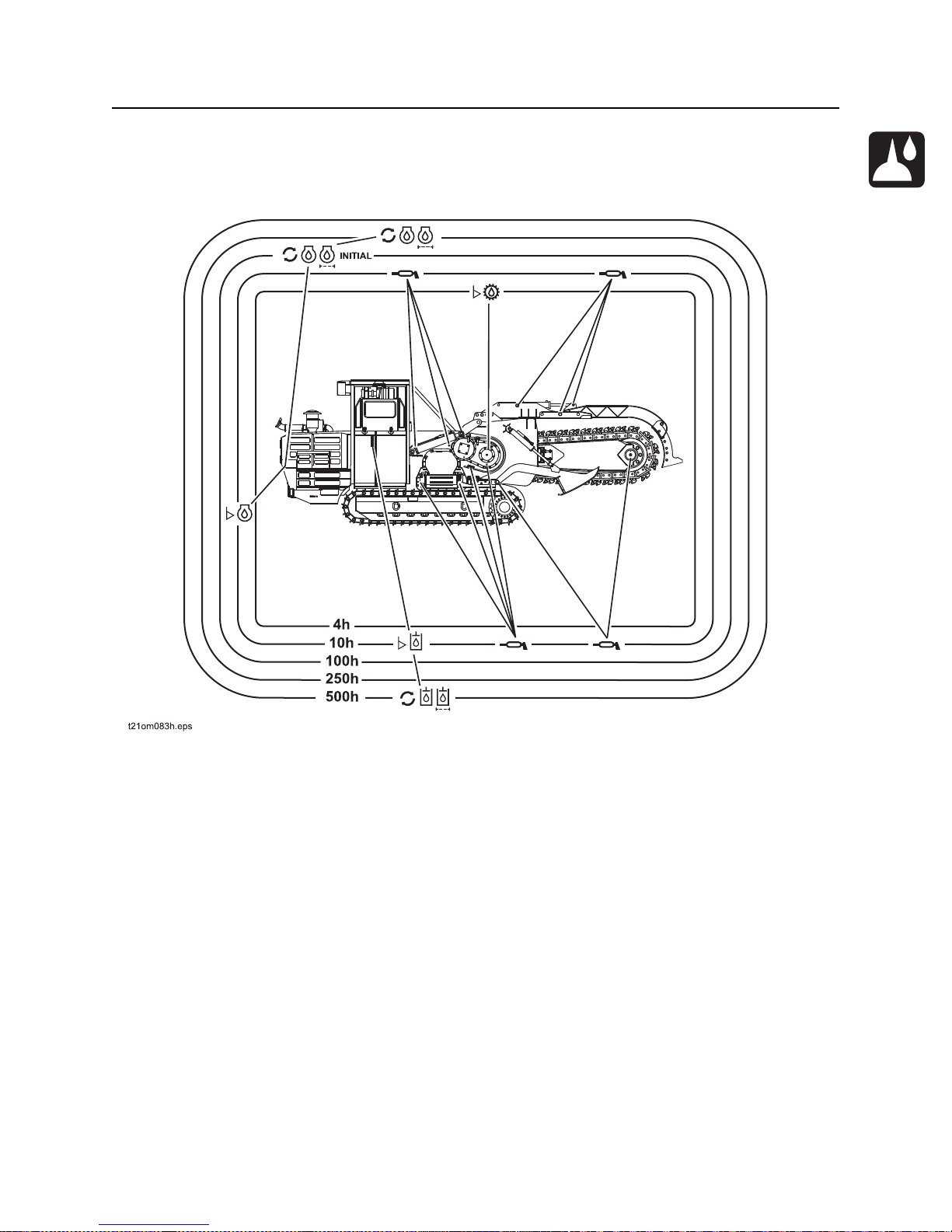
HT220 Operator’s Manual Service - 97
Lubrication Overview
Lubrication Overview
Lubrication Overview (left)
Page 99
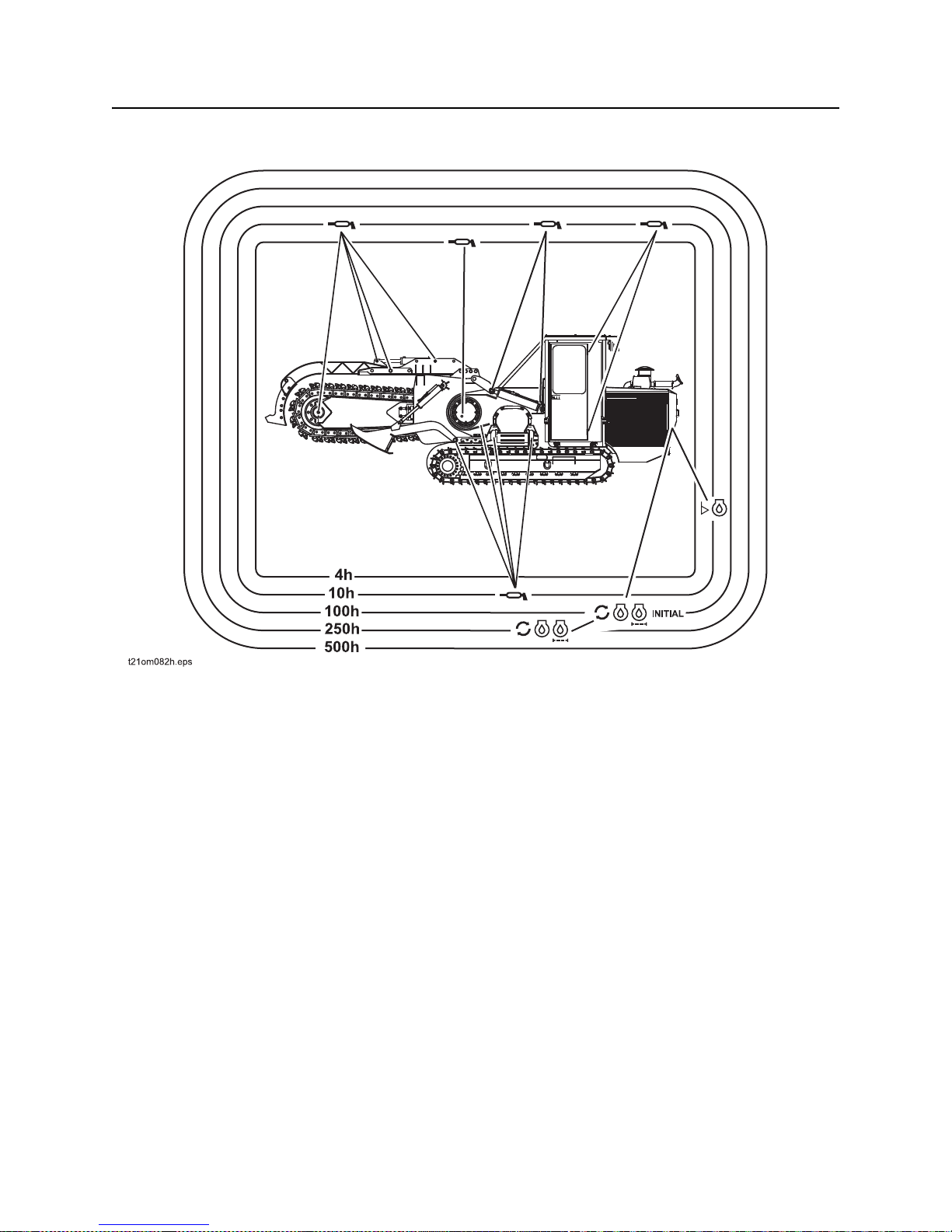
Service - 98 HT220 Operator’s Manual
Lubrication Overview
Lubrication Overview (right)
Page 100
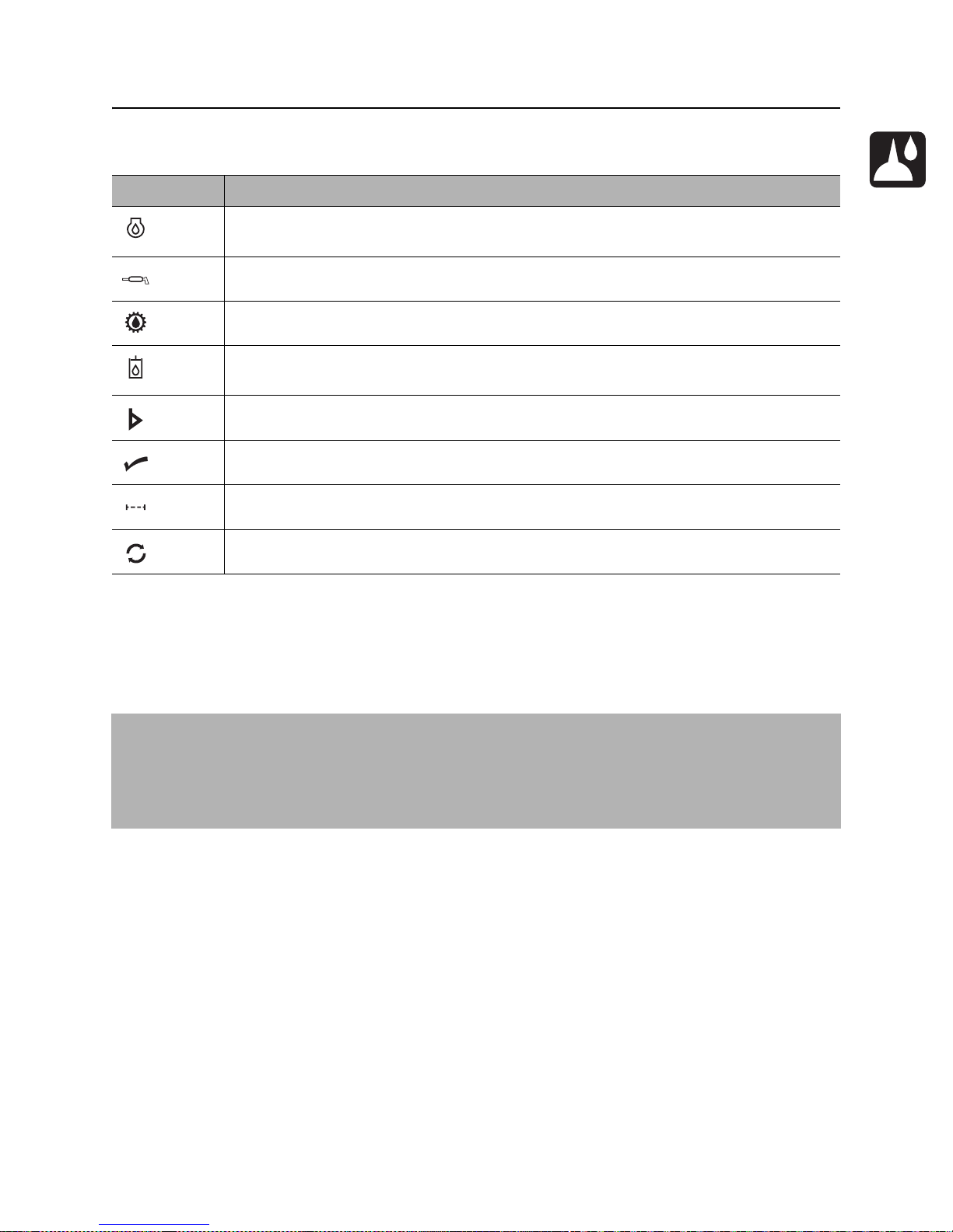
HT220 Operator’s Manual Service - 99
Recommended Lubricants/Service Key
Recommended Lubricants/Service Key
Item Description
DEO Diesel engine oil meeting API service classification CF-4 or E1-96 and SAE viscosity
recommended by engine manufacturer (SAE 15W40)
MPG Multipurpose grease meeting ASTM D217 and NLGI 5
MPL Multipurpose gear oil meeting API service classification GL-5 (SAE 80W90)
THF Tractor hydraulic fluid, similar to Phillips 66 HG, Mobilfluid 423, Chevron Tractor
Hydraulic Fluid, Texaco TDH Oil, or equivalent
Check level of fluid or lubricant
Check condition
Filter
Change, replace, adjust, service, or test
Proper lubrication and maintenance protects Ditch Witch equipment from damage and failure. Service
intervals listed are for minimum requirement s. In extreme conditions, service machine more frequently.
Use only recommended lubricants. Fill to capacities listed in “Specifications” on page 117.
®
For more information on engine lubrication and maintenance, see your Cummins
NOTICE:
• Use only genuine Ditch Witch parts, filters, approved lubricants, TJC, and approved coolants to
maintain warranty.
• Use the “Service Record” on page 143 to record all required service to your machine.
engine manual.
 Loading...