

CM Truck Beds SS Bed, TM Bed, WD Bed, RD Bed, PL Bed Owner's Manual
...

2
CM Truck Beds Owner’s Manual
Table of Contents
Welcome 4
SS Truck Bed
Bed Installation 6
Wiring 7
Fuel Filler Assembly Installation 9
RD Truck Bed
Bed Installation 10
Wiring 11
Fuel Filler Assembly Installation 13
SK Truck Bed
Bed Installation 14
Wiring 15
Fuel Filler Assembly Installation 17
ER Truck Bed
Bed Installation 18
Wiring 19
Fuel Filler Assembly Installation 21
TM Truck Bed
Bed Installation 22
Wiring 23
Fuel Filler Assembly Installation 25
WD Truck Bed
Bed Installation 26
Wiring 27
Fuel Filler Assembly Installation 29
GP Truck Bed
Bed Installation 30
Wiring 31
Fuel Filler Assembly Installation 33
PL Truck Bed
Bed Installation 34
Wiring 35

3
Fuel Filler Assembly Installation 37
RD-AL Truck Bed
Bed Installation 38
Wiring 39
Fuel Filler Assembly Installation 41
Technica l Information 42
CM.02.15.06

4
WELCOME TO THE CM TRUCK BEDS TEAM
Thank you for purchasing your new CM truck bed. You have
now joined an ever-growing team of quality conscious truck
equipment buyers.
CM Truck Beds is a wholly owned subs id ia r y of Contract
Manufacturer, L.L.C. manufacturing under the name of “CM
Truck Beds.” Our beds ar e des igned and manufactured to
give you many years of reliable service. The combina tion of
quality materials and top crafts m a nship continues to put CM
Truck Beds above the r es t.
The safety an d c om fort of your cargo is the highest priority in
every CM design and ma nufacturing phase. However, as a
responsible tr uck bed owner, it is your responsibility to be
familiar with your new truck bed an d to follow safety
guidelines and the r ec omm ended maintenance instruc tions to
ensure you have many years of safe hauling.
As you begin to use your new CM truck bed, th is Owner’ s
Manual will allow you to become more f amiliar with the
operation, m a intenance, and care of your truck bed. This
manual will reference excerpts from other manufacturer’s
manuals which have components on CM Truck Beds products.
Disclaimer
All truck beds manuf a c tured by CM Truck Beds are designed
to be used within the specific engineering guidelines. It is
suggested that all truc k beds are to be used as designated by
the manufacturer.
CM Truck Beds reserv es the right to make any change in
paint, design or construction a s necessary for engineering. All
visual representati on, specification and guidelin es a r e based
on the latest product information available at the time of this
publication. All truck beds manufactured by Contract
Manufacturer, L . L.C ., d.b.a. “CM Truck Beds” are covered in
this publicat ion, with minor exceptions. For more information,
call us at 580-795-9999 or, you ca n write us at 1102 North
Industria l Road, Madill, OK 73446, e-mail:
customerservice@cmtrailers.com, web site:
www.cmtruckbeds.com.
5
6
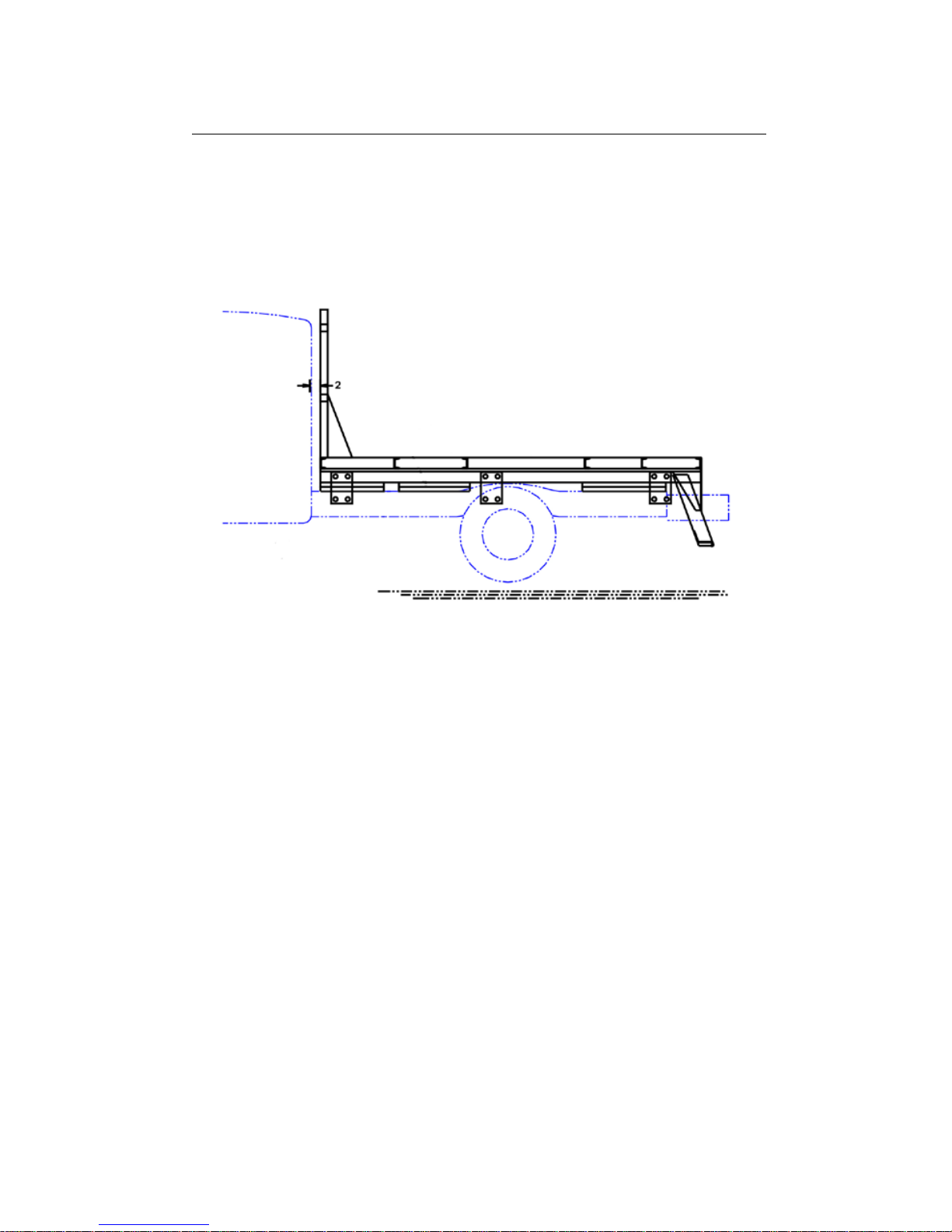
SS Bed
BED INSTALLATION
Schematic
Explanation
Measure frame on tr uck and runners on bed to make sure you
have the right bed for th e application. Then, using a spacer
between the runn er s and the frame, position the bed s o that
the headache rack does not stick up over the cab of the truck
more than 1 ½”. Ther e should be 2” of s pa c e between the cab
and the headach e ra ck on the bed.
Attach fastener on each side of the front, middle, and r ea r ;
bolt to the fram e, and then either b olt the fastener to your
bed runners or weld th em up solid. *
* NOTE: Attachm e nt com ponents are not supplied. Please use
adequate material to fasten the frame and bed togethe r . For any
questions concerning materials, please contact the manufacturer.
* CAUTION: Observe safety precautions w he n using a welde r o n
your vehicle. These are only reco mmend ations and installation design
is the responsibility of the ins taller . Fo ll o w vehic le ma nuf a c turer
specifications when attac hing plates to the truck frame.

7
WIRING DIAGRAM: FORD, 2000 OR OLDER
CHEVY, 2002 OR OLDER DODGE
Wiring Schematic
Explanation
* NOTE: Observe all vehicle manufacturer recommend ati ons w he n
working with or connecting to vehic le elec tr ic a l sys te ms. These wiri ng
instructions were create d for truck s usi ng comb ined bra ke and turn
signal lights. Keep all lights turne d off w he n making conne c tions .
The wiring is installed starting on the right side of the
headache rack, running through it and picking up the left
side. It then tr avels back to the center of the bed w here there
is a 6 pin connection. The center harness is connected h er e
and runs bac k to the tail skirt wher e there is another 6 pin
connection for the rear skirt h a r ness. Before the rea r
connection is a 6 wire pig tail to tie direc tly into the truc k
functions.

8
WIRING DIAGRAM: 2003 DODGE TO PRESENT
AND 2001 CHEVY TO PRESENT
Wiring Schematic
Explanation
* NOTE: Observe all vehicle manufacturer recommend ati ons w he n
working with or connecting to vehic le elec tr ic a l sys te ms. These wiring
instructions were create d for truck s usi ng separate br ak e and turn
signal lights. Keep all lights turne d off w he n making conne c tions .
The wiring is installed starting on the right side of the
headache rack, running through it and picking up the left
side. It then travels ba c k to the center of the bed where there
is a 6 pin connection. The center harness is connected h er e
and runs bac k to the tail skirt wher e there is another 6 pin
connection for the rear skirt h a r ness. Before the rea r

9
connection is a 6 wire pig tail to tie directly into the truck
functions.
* NOTE: Wire s that ar e not used from harness need to have a scotch
lock put on the end so they don’t short out against the steel of the
truck bed.
FUEL FILLER ASS EM B LY INSTALLATION
* WARNING: Ins talla tio n requires cutting and grinding. Keep all
ignition sources away when working with fuel tank filler pipe, or
serious injury or death can occur.
* CAUTION: Fuel tank filler pipe must be installed ac cording to
vehicle requirements. Please read Owner’s Manual. F ollow fuel tank
pipe manufacturer’s instr uc ti on or ser i o us injury c an occur .
The fuel filler door has been pre-determined to best suit the
tank location on your vehicle.
Fuel filler door has been tacked shut and welds will eith er
need to be cut or grinded off . Af ter gr inding welds, you should
be able to open spring loaded f ill er door.
Filler tube (not supplie d by CM Truck Beds) should be routed
to fuel tank of your vehicle, per instructions supp lied with
filler tube.
10
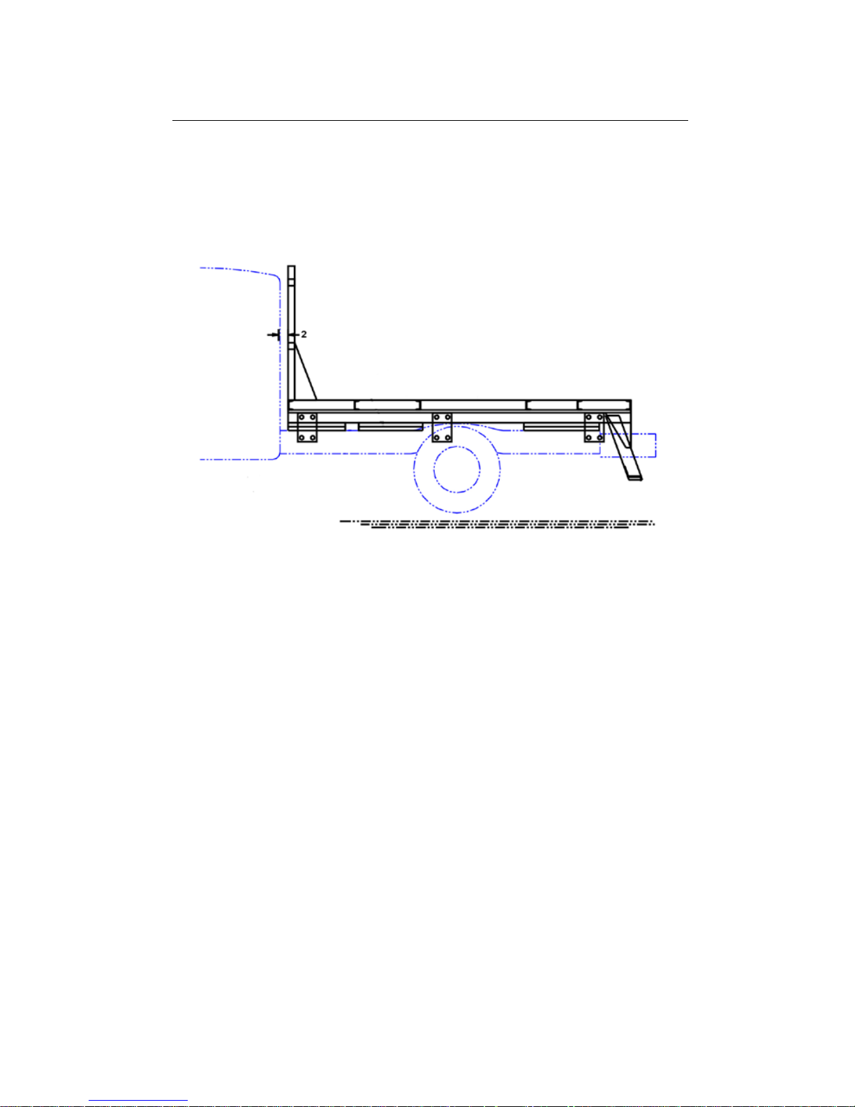
RD Bed
BED INSTALLATION
Schematic
Explanation
Measure frame on tr uck and runners on bed to make sure you
have the right bed for th e application. Then, using a spacer
between the runn er s and the frame, position the bed so that
the headache rack does not stick up over the cab of the truck
more than 1 ½”. Ther e should be 2” of s pa c e between the cab
and the headach e ra ck on the bed.
Attach fastener on each side of the front, middle, and r ea r ;
bolt to the fram e, and then either bolt the fastener to y our
bed runners or weld them up solid. *
* NOTE: Attachm e nt com ponents are not supplied. Please use
adequate material to fasten the frame and bed togethe r . For any
questions concerning materials, please contact the manufacturer.
* CAUTION: Observe safety pr ecautio ns when using a welder on
your vehicle. These are only reco mmend ations and installation design
is the responsibility of the ins taller . Fo ll o w vehic le ma nuf a c turer
specifications when attac hing plates to the truck frame.

11
WIRING DIAGRAM: FORD, 2000 OR OLDER
CHEVY, 2002 OR OLDER DODGE
Wiring Schematic
Explanation
* NOTE: Observe all vehicle manufacturer recommend ati ons w he n
working with or connecting to vehic le elec tr ic a l sys te ms. These wiri ng
instructions were create d for truck s usi ng comb ined bra ke and turn
signal lights. Keep all lights turne d off w he n making conne c tions .
The wiring is installed starting on the right side of the
headache rack, running through it and picking up the left
side. It then travels ba c k to the center of the bed where there
is a 6 pin connection. Th e center harness is connected here
and runs bac k to the tail skirt wher e there is another 6 pin
connection for the rear skirt h a r ness. Before the rea r
connection is a 6 wire pig tail to tie direc tly into the truc k
functions.

12
WIRING DIAGRAM: 2003 DODGE TO PRESENT
AND 2001 CHEVY TO PRESENT
Wiring Schematic
Explanation
* NOTE: Observe all vehicle manufacturer recommend ati ons w he n
working with or connecting to vehic le elec tr ic a l sys te ms. These wiri ng
instructions were create d for truck s usi ng separate br ak e and turn
signal lights. Keep all lights turne d off w he n making conne c tions .
The wiring is installed starting on the right side of the
headache rack, running through it and picking up the left
side. It then travels ba c k to the center of the bed where there
is a 6 pin connection. The center harness is connected h er e
and runs bac k to the tail skirt wher e there is another 6 pin
connection for the rear skirt h a r ness. Before the rea r

13
connection is a 6 wire pig tail to tie direc tly into the truck
functions.
* NOTE: Wire s that ar e not used from harness need to have a scotch
lock put on the end so they don’t short out against the steel of the
truck bed.
FUEL FILLER ASS EM B LY INSTALLATION
*WARNING: Installation requires c utting and grinding. Keep all
ignition sources away when working with fuel tank filler pipe, or
serious injury or death can occur.
*CAUTION: Fuel tank filler pipe mus t be installe d accor ding to
vehicle requirements. Please read Owner’s Manual. Follow fuel tank
pipe manufactur er’ s instruction or serious injury can occur.
The fuel filler door has been pre-determined to best suit the
tank location on your vehicle.
There is a knoc k out plug where your fuel fill nozzle is to be
located. It is tack welded in place. To remove it, use a
hammer and punch and knock it out of the bed.
Filler tube (not supplie d by CM Truck Beds) should be routed
to fuel tank of your vehicle, per instructions supp lied with
filler tube.
14
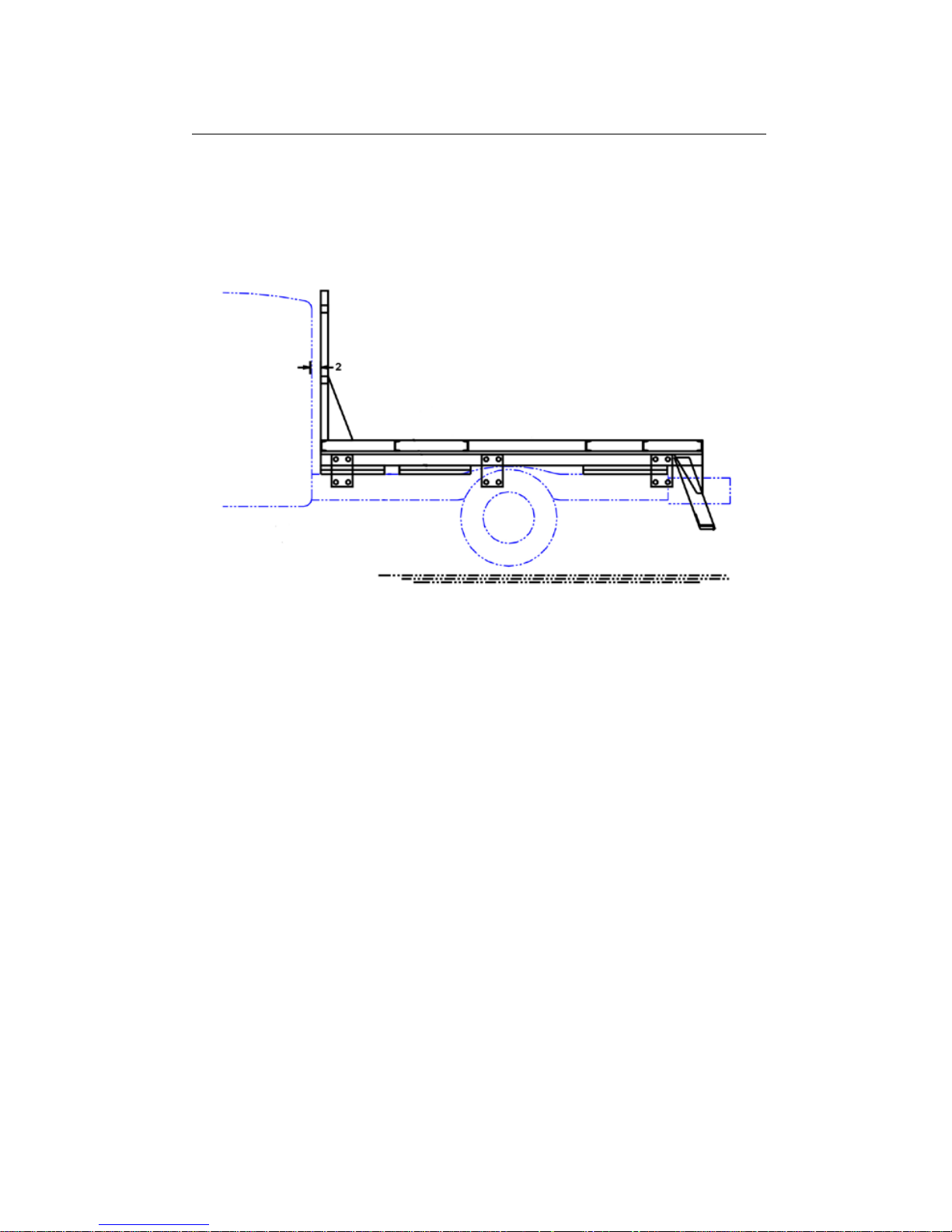
SK Bed
BED INSTALLATION
Schematic
Explanation
Measure frame on truck and runners on bed to make sure you
have the right bed for th e application. Then, using a spacer
between the runn er s and the frame, position the bed so that
the headache rack does not stick up over the cab of the truck
more than 1 ½”. There should be 2” of space between the c a b
and the headach e ra ck on the bed.
Attach fastener on each side of the front, middle, and r ea r ;
bolt to the fram e, and then either bolt the fastener to y our
bed runners or weld th em up solid. *
* NOTE: Attachm e nt com ponents a r e no t supplied. Please use
adequate material to fasten the frame and bed togethe r . For any
questions concerning materials, please contact the manufacturer.
* CAUTION: Observe safety pr ecautio ns when using a welder on
your vehicle. These are only reco mmend ations and installation design
is the responsibility of the ins taller . Fo ll o w vehic le ma nuf a c turer
specifications when attac hing plates to the truck frame.
 Loading...