

CMT ORANGE TOOLS CMT792 Instruction Manual
CMT792
Set of 2 magnetic knife setting jigs
Juego de 2 reguladores magnéticos para cuchillas de cepilladoras
Jeu de 2 régulateurs magnétiques de couteaux de rabotage
Set di 2 allineatori magnetici per coltelli da pialla
Set mit 2 magnetischen Reglern für Hobelmesser
High precision adjustment for perfect knife alignment
Fast knife setup and adjustment
TWO SETUP POSSIBILITIES
Instruction Manual
Manual de instrucciones - Manuel d’instructions
Manuale di istruzioni - Gebrauchsanweisungen
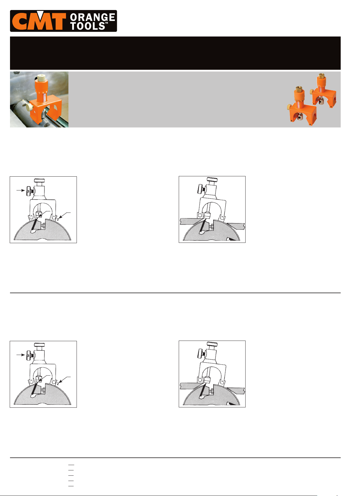
A) Positioning on the tool holder body: plan-
3
1
1. Magnetic stop
2. Joints with magnetic connectors
3. Lock screw
ers, thickness planers, combined machines,
etc., with detection of the knife position.
Detection of the knife position.
2
Remark: place the first jig’s magnetic head
onto the knife at one end. Record the figures
on the scale. Position the second jig on the
tool holder body with its magnetic head onto
the knife at the opposite end by setting up the
magnetic head with the previously-recorded
figures. You will then obtain a perfect knife
alignment.
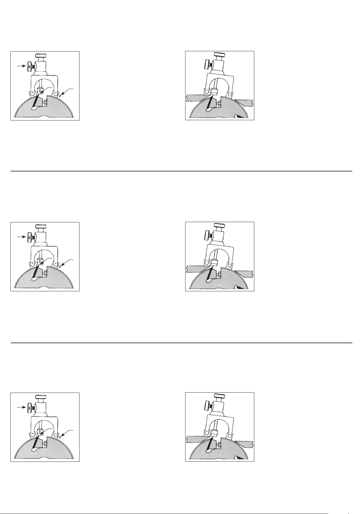
holder body. Position the magnetic head on the knife at one end. Record the figures
on the scale. Place the second jig with the magnetic head onto the knife at its opposite end and adjust it by setting up the magnetic head with the previously-recorded
figures. You will then obtain a perfect knife alignment.
Alta precisión de ajuste que permite una perfecta alineación de las cuchillas
Rapidez de montaje y de alineación
DOS POSIBILIDADES DE MONTAJE
A) Colocación sobre el cuerpo de la por-
3
1
1. Tope magnético
2. Rótulas con bornes magnéticos
3. Tornillo de bloqueo
tacuchilla: cepilladoras, regruesadoras, máquinas combinadas, etc., y detección de la
posición de la cuchilla.
2
Detección de la posición de la cuchilla.
Nota: coloque el cabezal magnético del primer regulador sobre la cuchilla, en su extremo.
Registre las cifras de su escala. Posicione el
segundo regulador sobre el portacuchillas con
su cabezal magnético sobre la cuchilla, en su
extremo opuesto, y ajuste el cabezal con las
mismas cifras registradas en el primer regulador. Obtendrá así una alineación perfecta.
rótula sobre el portacuchillas. Coloque el cabezal magnético sobre la cuchilla, en
su extremo. Registre las cifras de su escala. Posicione el segundo regulador con su
cabezal magnético sobre la cuchilla, en su extremo opuesto, y ajuste el cabezal con
las mismas cifras registradas en el primer regulador. Obtendrá así una alineación
perfecta.
B) Direct positioning on both the planer
table and the tool holder body: detection
of the knife position (allowing for a perfect
alignment, even if the planer table is worn
out).
Detection of the knife position (allowing for
a perfect alignment, even if the planer table
is worn out).
Remark: place one joint of the first jig on the
planer table and the other joint on the tool
B) Colocación sobre ambos, mesa de ce-
pidallora y portacuchillas: detección de la
posición de la cuchilla (que permite una
alineación perfecta, aunque la mesa de cepilladora esté desgastada).
Detección de la posición de la cuchilla (permite una alineación perfecta, aunque la mesa
de cepilladora esté desgastada).
Nota: posicione una rótula del primer regulador sobre la mesa de cepidallora y la otra
© C.M.T. UTENSILI S.P.A. TM: CMT, the CMT logos, CMT ORANGE TOOLS and the orange color applied to the tool surfaces are trademarks of C.M.T. UTENSILI S.p.A.
TM: CMT, los logotipos CMT, CMT ORANGE TOOLS y el color anaranjado del revestimiento de la superficie de las herramientas son marcas registradas de C.M.T. UTENSILI S.p.A.
TM: CMT, les logos CMT, CMT ORANGE TOOLS et la couleur orange du revêtement de la surface des outils sont des marques déposées de la société C.M.T. Utensili S.p.A.
TM: CMT, i loghi CMT, CMT ORANGE TOOLS e il colore arancio del rivestimento della superficie degli utensili sono marchi registrati di C.M.T. UTENSILI S.p.A.
TM: CMT, die CMT Logos, CMT ORANGE TOOLS und die orangene Farbe der Werkzeugflächen sind eingetragene Warenzeichen von C.M.T. Utensili S.p.A.
03.60.0216
Réglage de haute précision pour un parfait alignement des couteaux
Rapide Montage et réglage des couteaux
DEUX OPTIONS DE MONTAGE
A) Placement sur le corps du porte-outil:
3
1
1. Arrêt magnétique
2. Joints avec connecteurs magnétiques
3. Vis d’arrêt
raboteuses, raboteuses bois, machines combinées, etc., et détection de la position du
couteau.
2
Détection de la position du couteau.
Remarques : placez la tête magnétique du
premier régulateur sur le couteau, à une extrémité. enregistrez les chiffres de l’échelle. Positionnez le deuxième régulateur sur le corps du
porte-outil avec la tête magnétique sur le couteau à l’extrémité opposée, en réglant la tête
magnétique avec les chiffres précédemment
enregistrés. Vous obtiendrez un parfait alignement du couteau !
porte-outil. Positionnez la tête magnétique sur le couteau, à une extrémité. Enregistrez les chiffres de l’échelle. Placez le deuxième régulateur sur le corps du porteoutil avec la tête magnétique sur le couteau à l’extrémité opposée, en réglant la tête
magnétique avec les chiffres précédemment enregistrés. Vous obtiendrez un parfait
alignement du couteau !
Perfetto allineamento dei coltelli grazie alla regolazione di precisione
Rapidità nel montaggio e nella regolazione dei coltelli
DUE POSSIBILITÀ DI MONTAGGIO
CMT792
B) Placement sur l’établi de raboteuse
et le corps du porte-outil: détection de la
position du couteau (pour un alignement
parfait, même si l’établi de la raboteuse
est usé).
Détection de la position du couteau (pour un
alignement parfait, quand même l’établi de
raboteuse est épuisé). Remarques : placez
un joint du premier régulateur sur l’établi
de raboteuse et l’autre joint sur le corps du
A) Posizionamento sul corpo dell’utensile:
3
1
1. Arresto magnetico
2. Articolazioni con morsetti magnetici
3. Vite d’arresto
piallatrici, piallatrici a spessore, macchine
combinate, ecc., con rilevamento della posizione del coltello.
2
Rilevamento della posizione del coltello.
Nota: posizionare la testina magnetica del primo allineatore sopra un’estremità del coltello.
Registrare i valori riportati sulla scala. Utilizzare
il secondo allineatore appoggiandolo sul corpo
dell’utensile e posizionando la testina magnetica sopra l’altra estremità del coltello, regolandola con gli stessi valori registrati su scala
dal primo allineatore. Otterrete così il perfetto
allineamento del coltello.
tavolo della piallatrice e l’altra sul corpo dell’utensile. Collocare la testina magnetica
sopra un’estremità del coltello per rilevarne la posizione registrando i valori riportati
sulla scala. Posizionare il secondo allineatore con la testina magnetica sopra l’altra
estremità del coltello, regolandola con gli stessi valori registrati su scala dal primo
allineatore. Otterrete così il perfetto allineamento del coltello.
Hochpräzisions-Einstellungen zur richtigen Ausrichtung der Messer
Schnelle Montage und Einstellung
ZWEI MONTAGEMÖGLICHKEITEN
A) Positionierung auf dem Gehäuse der Werk-
3
zeughalter: Hobelmaschinen, große Hobelmaschinen, kombinierte Maschinen, usw., und
Erfassung der Messerposition.
B) Posizionamento sul tavolo della pial-
latrice e corpo dell’utensile: rilevamento
della posizione del coltello (garantisce un
allineamento perfetto anche in caso il tavolo della fresatrice fosse usurato).
Rilevamento della posizione del coltello (garantisce un allineamento perfetto anche in
caso il tavolo della fresatrice fosse usurato).
Nota: per la regolazione dei coltelli posizionare un’articolazione del primo allineatore sul
B) Positionierung auf beiden Hobeltisch und
Gehäuse der Werkzeughalter: Erfassung der
Messerposition (zur richtigen Ausrichtung,
auch wenn der Hobeltisch abgenutzt ist).
1
1. Magnetischer Halt
2. Gelenke mit magnetischen Verbindern
3. Fixierschraube
Erfassung der Messerposition. Bitte achten Sie
2
darauf: Stellen Sie den magnetischen Kopf des
ersten Reglers auf das Messer, an einem Ende
ein. Vermerken Sie die aufgezeichneten Zahlen
auf der Skala, wenn der Kopf in Berührung mit
dem Messer gekommen ist. Setzen Sie den zweiten Regler auf das Gehäuse der Werkzeughalter
mit dem magnetischen Kopf auf das Messer, an
dem gegenüberliegenden Ende. Stellen Sie den
magnetischen Kopf mit den vorher aufgezeichneten Zahlen ein, wenn er auch in Kontakt mit dem
Messer gekommen ist. Schließlich werden Sie
eine richtige Ausrichtung der Messer erhalten.
Erfassung der Messerposition (zur richtigen Ausrichtung, auch wenn der Hobeltisch abgenutzt
ist). Bitte achten Sie darauf: Stellen Sie ein
Gelenk des ersten Reglers auf den Hobeltisch
und das andere Gelenk auf das Gehäuse der
Werkzeughalter ein. Setzen Sie den magneti-
schen Kopf auf das Messer, an einem Ende. Vermerken Sie die aufgezeichneten Zahlen auf der Skala, wenn den Kopf in Berührung mit
dem Messer gekommen ist. Stellen Sie den zweiten Regler auf das Gehäuse der Werkzeughalter mit dem magnetischen Kopf, an dem gegenüberliegenden Ende ein. Setzen
Sie den magnetischen Kopf mit den vorher aufgezeichneten Zahlen ein, wenn er auch in
Kontakt mit dem Messer gekommen ist. Schließlich werden Sie eine richtige Ausrichtung
der Messer erhalten.
 Loading...