

Page 1

DP Series
LOUDSPEAKER MANAGEMENT
User Manual
Page 2
Introduction
1. Re ad these instructions.
2. Ke ep these instructions.
3. Heed all war nin gs.
4. Follow all instructions.
5. Do not use this apparatus near wat er.
6. Clean only with dry clo th.
7. Do not block any ven tilati on openi ngs . Instal l i n accordanc e with t he manufacture’s instruction s.
8. Do not install near any heat sources such as radiators, heat registers, stoves, or other a ppa ratus (i ncludi ng ampli fie rs)
that produce heat.
9. Do not defeat the safety purpose of the polarized or grounding- typ e plug. A polarized plug has two blades with one
wider than the other. A g rou nding-type plu g has two blades and a third grounding pro ng. The wid e blade or the third
prong are provided for you r safety. If the provided plug does not fit into your outlet, consult an electricia n for
replacement of the obsolete outlet.
10. Protect the power co rd from being walked on or pinched particularly at plugs, convenience receptacles, and the
point where they exit from the appara tus .
11. Use only attachments/accessories specified by the man ufacturer.
12. Use only with the cart, stand, tripod, bracket, or table specified by the man ufa cturer, or so ld with the apparatus.
When a cart is used, use caution when moving the cart/apparatus combination to avoid injury from tip-o ver.
13. Unplug this apparatus during lighting storms or when unuse d for long periods of time.
14. Refer all servicing to qualified service personal. Sevicin g is required when the apparatus has been dam age d in any
way, such as power supply cord or plug is damaged, liquid has been spilled or objects have fallen into the apparatus,
the apparatus has been exposed to rain or moisture, does not operate normally, or has been dropped.
15. The apparatus shall be c onnected to a MAINS socket out let with a protective earthing connection.
16. Where the MAINS plug or an appliance coupler is used as the dis con nect device , the disconnect device shall remain
readily operable.
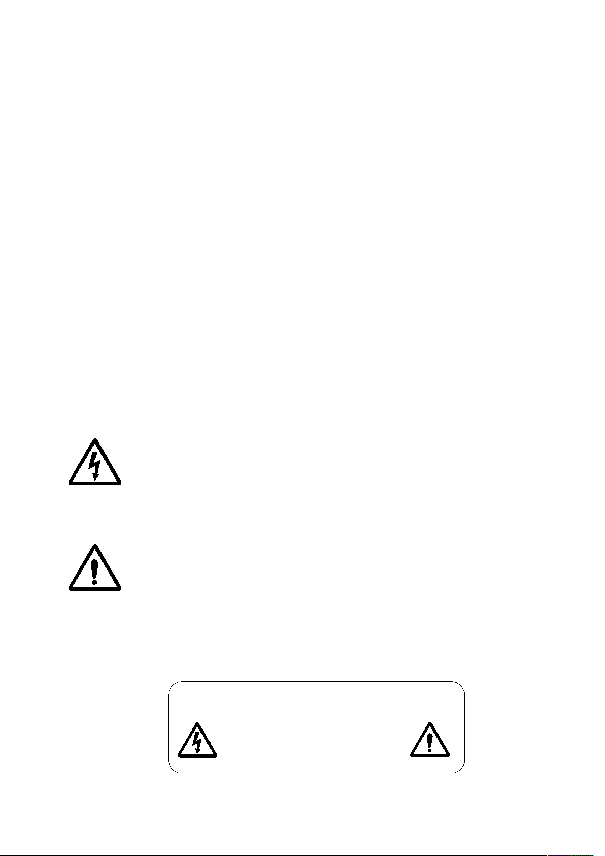
The symbol, wherever is appears, ale rts you to the presense of uninsul ate d dangerous voltage inside the
enclosure-voltage that may be sufficient to constitute a risk of shock.
The symbol, wherever is appears, ale rts you to important operating and maintenance instructions
in the accompanying literature. Please read the manual.
To reduce the risk of electric shock, do not remove the top cover ( or the r ear section ). No user serviceable
parts inside. Refer servicing to qualified personnel.
To reduce the risk of fire to electric shock, do not exp ose this ap pliance to rain and moisture. The apparatus
shall not be ex posed to dripping o r splashing liquids and no objects fi lled with l iquids, suc h as vases, shall b e
placed on the apparatus.
These service instructions are for use by qualified service personal only.
To reduce the risk of electric shock do n ot perform any servicing other than that contained in th e operation
instructions. Repairs have to be performed by qualified service personal.
CAUTION
RISK OF ELECTRIC SHOCK
DO NOT OPEN
DO NOT EXPOSE TO RAIN, MOISTURE,
DRIPPING OR SPLA SHI NG
Page 3

Introduction
The DP Series are powerfu l DSP based loudspe ake r processor s, ideally suited for install application, w her e they
combine the functions of a multitude of conventional produc ts in a compact 1U unit with exten siv e rem ote control
capabilities. To achieve this, the D P Series devices have two inputs, three inputs, and f our inputs and up to e ight
outputs.
Base crossover modes:
8 Outputs have 2x2 way, 2x3 way, 2x4 way, 4 +4 way, 5+3 way and 6+2 way.
6 Outputs have 2x2 way, 2x3 way, 4+2 way, 5+1 way a nd 6 way.
4 Outputs have 2x2 way, 3+1 way, 4 way and 2 MonoSub.
Units also offer “Source” for free assign signal, which allows completely flexible routing of any output from any
combination of inputs.
Each input has a gain c ont rol, variab le delay line, mult i-t ype filters. Filter types included parametric equa lisation,
high & low shelving, notch, band-pass, all-pass, variableQ highpass & lowpass.
Each output has a gain con trol, va ria ble delay line, highpass and lowpass crossover filters , seven band multi-type filters,
polarity, input signal source, a limiter. The crossover filters offer slopes of up to 48dB/Octave.
Security lock-out is avaiable for each parts.
Supply external d evi ce re mot e controls.
Remote port is and RS485.
RS232
Page 4
Front Panel
3
5
1
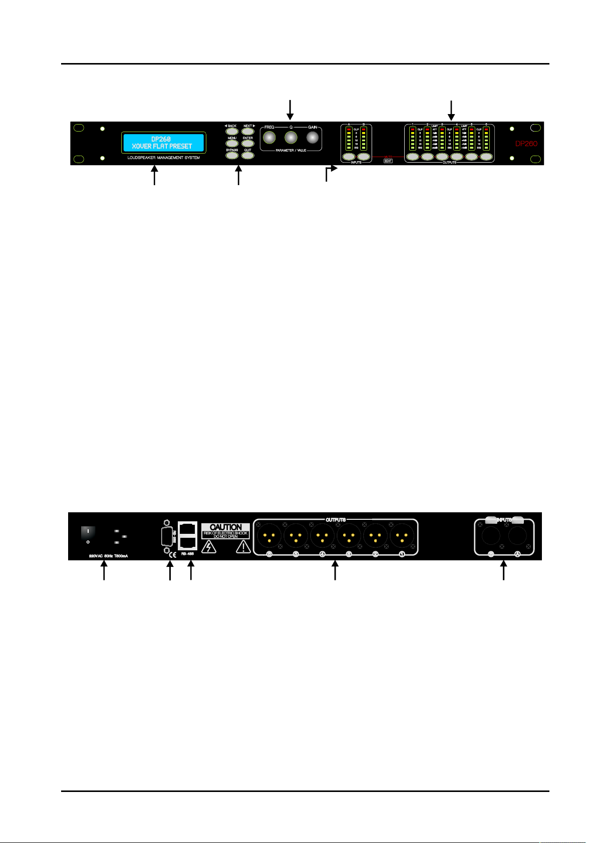
1. LCD Sreeen: Show, the name of last re cal led memory on the b ott om line of the screen, and current device mod el
name on the top line. Also used to show all parameters as they ar e edited, a nd all m enu selections .
2. BACK/ NEXT: Moves backwar ds or forward through list of parameters.
MENU: Activates the main menu.
BYPASS: Bypass filter.
QUIT: Quit key.
ENTER: Enter k ey.
3. Ro tary Encode rs: Three velocity encoders adjust parameters.
4. MUTE: These buttons illuminate when pressed and mute aud io for that channel.
(Press and Hold 3 seconds) Access current channel parameters.
5. Meters: Input and Output meters show dB fr om clipping point. Red CLIP LED sho w signal overflow, Yellow LED
show signal near -3dB.
2
4
Rear Panel
~
2
1
1. Power Switch: turns the device’s mains supply off and on.
2. RS232: RS232 st andard via a 9 p in D-type connector, for connection to PC.
3. RS485: RJ45 style sockets. Used for transmission of remote control data over long distance or multiply d evice
applications.
4. Audio Inputs: 3 pin XLR sockets are provided for each channel. Al l a re fully balanced, pin 2 hot, 3 cold, 1 screen.
5. Audio Outputs: 3 pin XLR sockets are provided for eac h channel. All are fully balanced, pin 2 hot, 3 cold, 1 screen.
3
5
4
Page 5
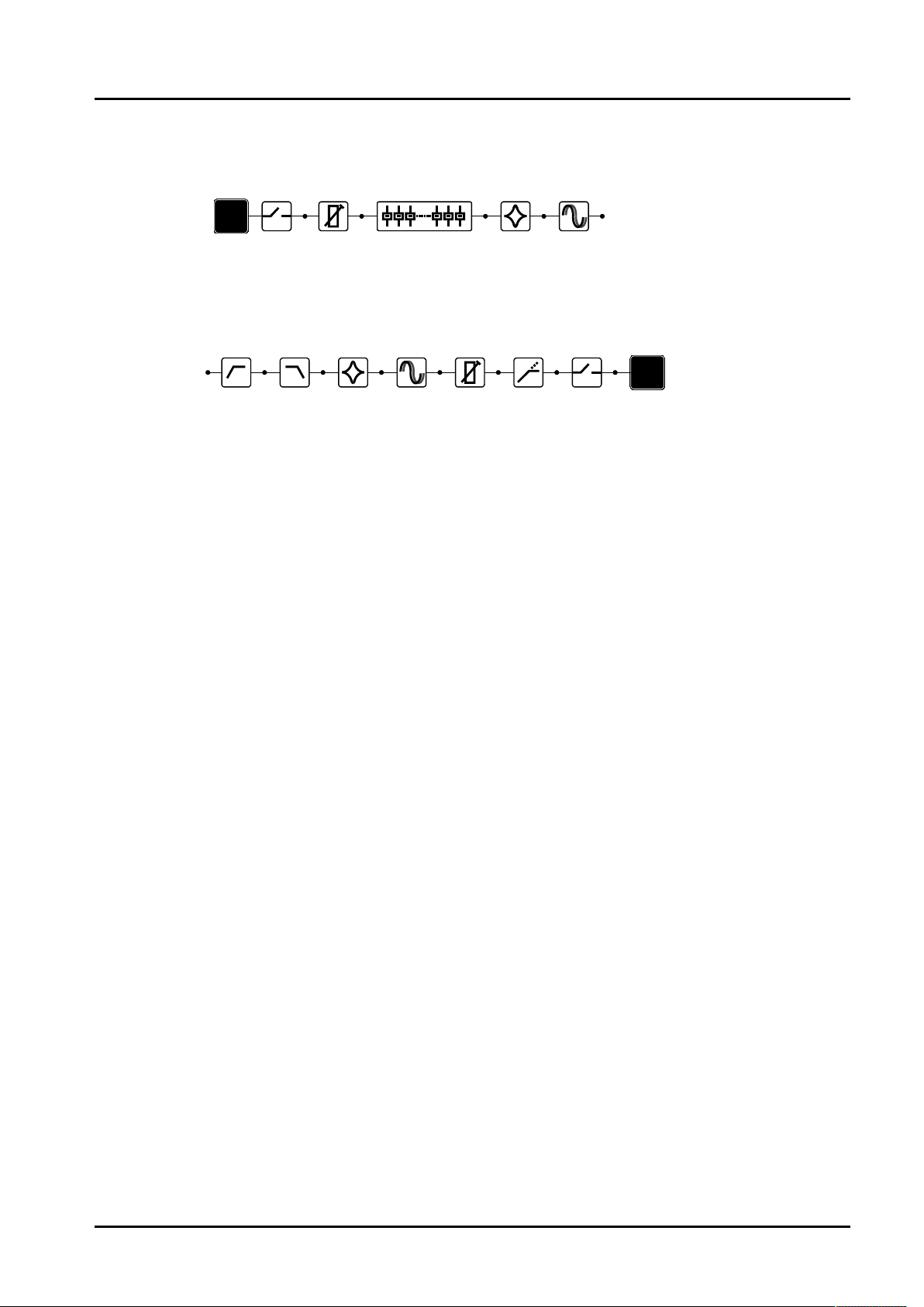
Diagram of input channels
INP UT
MUT E
GAI N
Gra phic EQ
A
Diagram of output channels
HPF LPF LIM ITER
PEQ
DEL AY
PEQ
GAI N MUT E
DEL AY
OUT PUT
1
Page 6
Input Gain
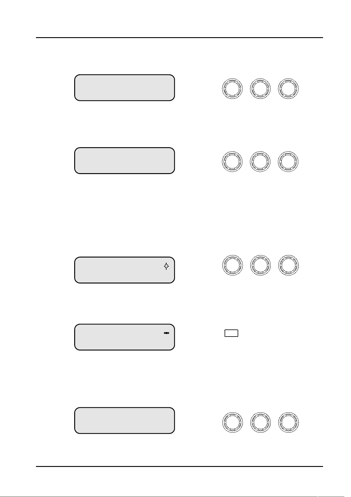
The range of the control over the inp ut gain is -40dB to +6dB in 0.1dB s teps.
InputA Gain
Gain = + 0 0dB.
Input Delay
The maximum avaiable delay depend on different devices.
InputA Delay
Delay = 0 000mS.
Gain
x10mS
3.43 m
Input Graphic EQ
The Graphic EQ only avaiable some devices.
The equaliser can be 1/3 or 2/3 Octave, and a gain ra nge of -12d B ~ +12d B i n 0.1dB steps.
InputA GEQ 1
1k00Hz ----- +0 0dB
Pressing BYPASS will bypass the entire Graphic EQ.
InputA GEQ 1
1k00Hz ----- +0 0dB
:
.
Frequen cy
:
.
Bypass
x1mS
343mm
x10uS
4mm
Gain
Input Link
Set link value for channel, while modify parameters, the channel of have same link value will mo dify togeth er.
InputA Link
Link = None
Link
Page 7
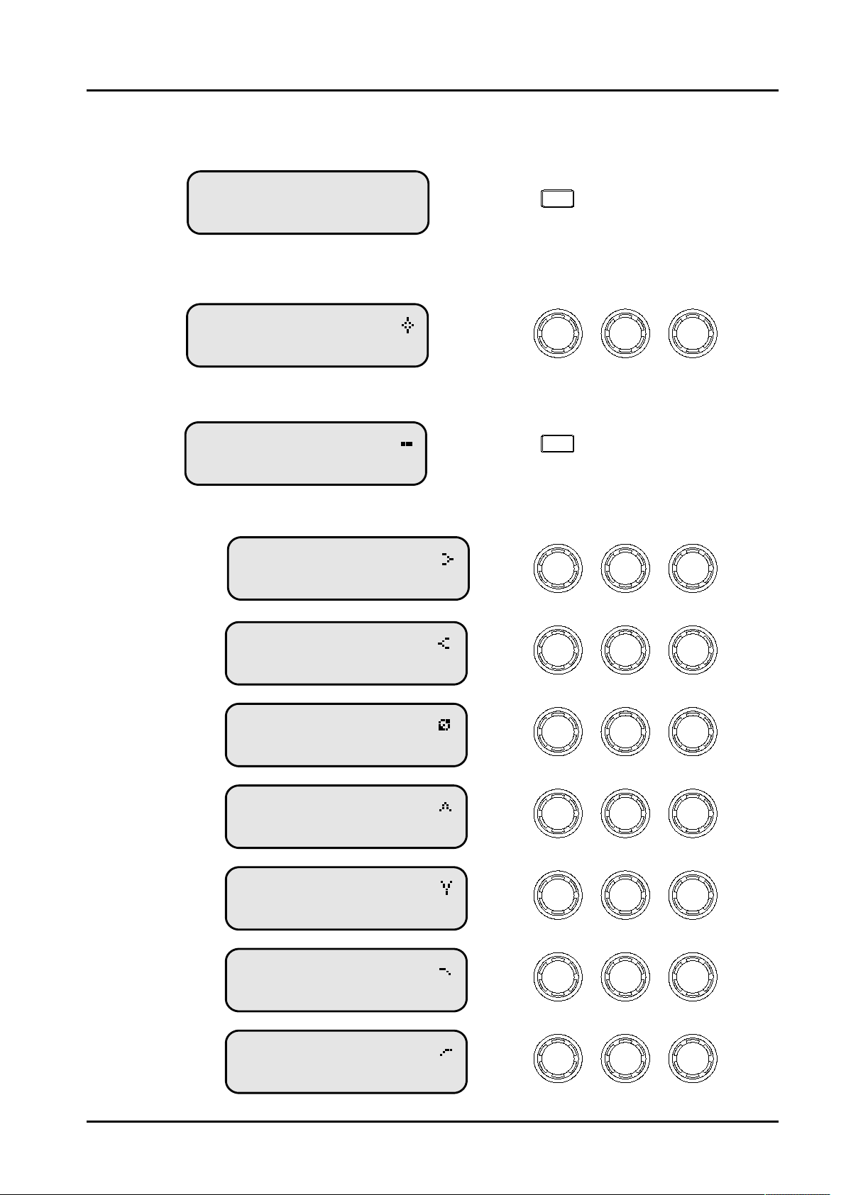
Input Parametric EQ
Pressing BYPASS will bypass the All bands EQ.
InputA All-EQ
Bypass = Off
The range of frequency is 20Hz to 20kHz in 1 /36 Octave. The range of Q is 0.4 to 128. The rang e of gain is -30dB to
+15dB in 0.1dB steps.
Bypass
InputA PEQ 01
1k00Hz Q=3 0 +0 0dB
Pressing BYPASS will bypass the current band EQ.
. .
InputA PEQ 01
1k00Hz Q=3 0 +0 0dB
While filter was in BYPASS ON, Changing the filter type is achieved by pressing E NTE R.
( )LoShelf
( )HiShelf
( )Allpass
InputA LSF 01
1k00Hz Q= 71 +0 0dB
InputA HSF 01
1k00Hz Q= 71 +0 0dB
InputA APF 01
1k00Hz Q= 71
. .
:
Frequen cy ‘Q’
:
Bypass
:
. .
Frequen cy ‘Q’
:
. .
Frequen cy ‘Q’
:
. -----
Gain
Gain
Gain
( )Bandpass
( )Notch
( )Lowpass
( )Highpass
InputA BPS 01
1k00Hz Q= 71
. -----
InputA NOT 01
1k00Hz Q= 71
. -----
InputA LPF 01
1k00Hz Q= 71
. -----
InputA HPF 01
1k00Hz Q= 71
. -----
:
:
:
:
Frequen cy ‘Q’
Frequen cy ‘Q’
Frequen cy ‘Q’
Frequen cy ‘Q’
Frequen cy ‘Q’
Page 8
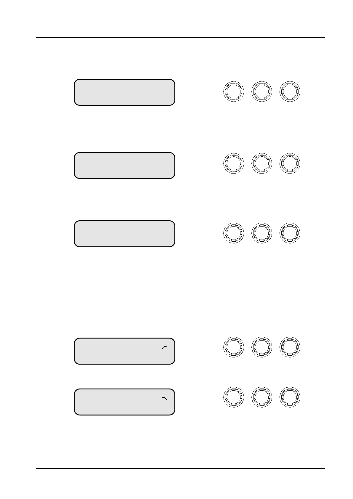
Output Gain
The range of the control over the inp ut gain is -40dB to +15dB in 0 .1dB steps.
Out1 Output1 Gain
Output Gain = + 0 0dB.
Output Polarity
The polarity ( or phase) o f each o utp ut may be s witched ind ividually.
Out1 Output1 Polarity
Polarity = [+]
Output Delay
The maximum avaiable delay depend on different devices.
Out1 Output1 Delay
Delay = 0 000mS.
Output Highpass/Lowpass Filter
x10mS
3.43 m
x1mS
343mm
Gain
- or +
x10uS
4mm
The highpass/lowp ass filter on each output has a fr equency range of 20Hz to 20kHz in 1/36 Octave steps.
Crossover slope c an be 6dB, 12dB, 18dB, 24dB, 36dB and 48dB/Octave.
Filter type can be Butterworth, Linkwitz-Riley, Bessel.
Out1 Output1 HPF
20 5Hz Butwrth 24dB.
Frequen cy
Slope
Out1 Output1 LPF
20k2Hz Lnk/Ril 48dB
Frequen cy
Slope
Page 9
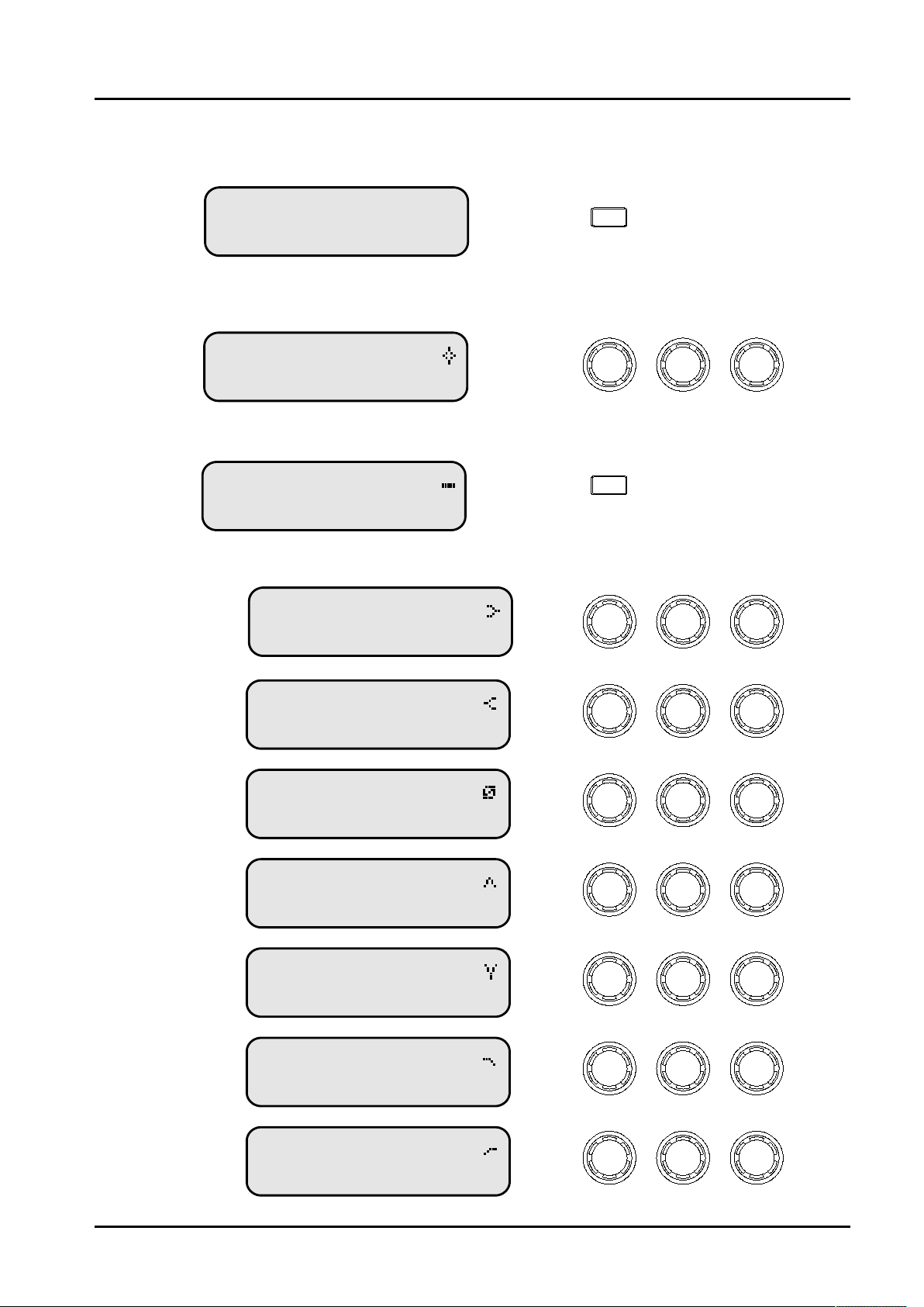
Output Parametric EQ
Pressing BYPASS will bypass the All bands EQ.
Out1 Output1 All-EQ
Bypass = Off
The range of frequency is 20Hz to 20kHz in 1 /36 Octave. The range of Q is 0.4 to 128. The rang e of gain is
-30dB to +15dB in 0.1dB s tep s.
Bypass
Out1 Output1 PEQ 01
1k00Hz Q=3 0 +0 0dB
Pressing BYPASS will bypass the current band EQ.
. .
Out1 Output1 PEQ 01
1k00Hz Q=3 0 +0 0dB
While filter was in BYPASS ON, Changing the filter type is achieved by pressing E NTE R.
( )LoShelf
( )HiShelf
( )Allpass
Out1 Output1 LSF 01
1k00Hz Q= 71 +0 0dB
Out1 Output1 HSF 01
1k00Hz Q= 71 +0 0dB
Out1 Output1 APF 01
1k00Hz Q= 71
. .
:
Frequen cy ‘Q’
:
Bypass
:
. .
Frequen cy ‘Q’
:
. .
Frequen cy ‘Q’
:
. -----
Gain
Gain
Gain
( )Bandpass
( )Notch
( )Lowpass
( )Highpass
Out1 Output1 BPS 01
1k00Hz Q= 71
. -----
Out1 Output1 NOT 01
1k00Hz Q= 71
. -----
Out1 Output1 LPF 01
1k00Hz Q= 71
. -----
Out1 Output1 HPF 01
1k00Hz Q= 71
. -----
:
:
:
:
Frequen cy
Frequen cy
Frequen cy
Frequen cy
Frequen cy
‘Q’
‘Q’
‘Q’
‘Q’
‘Q’
Page 10
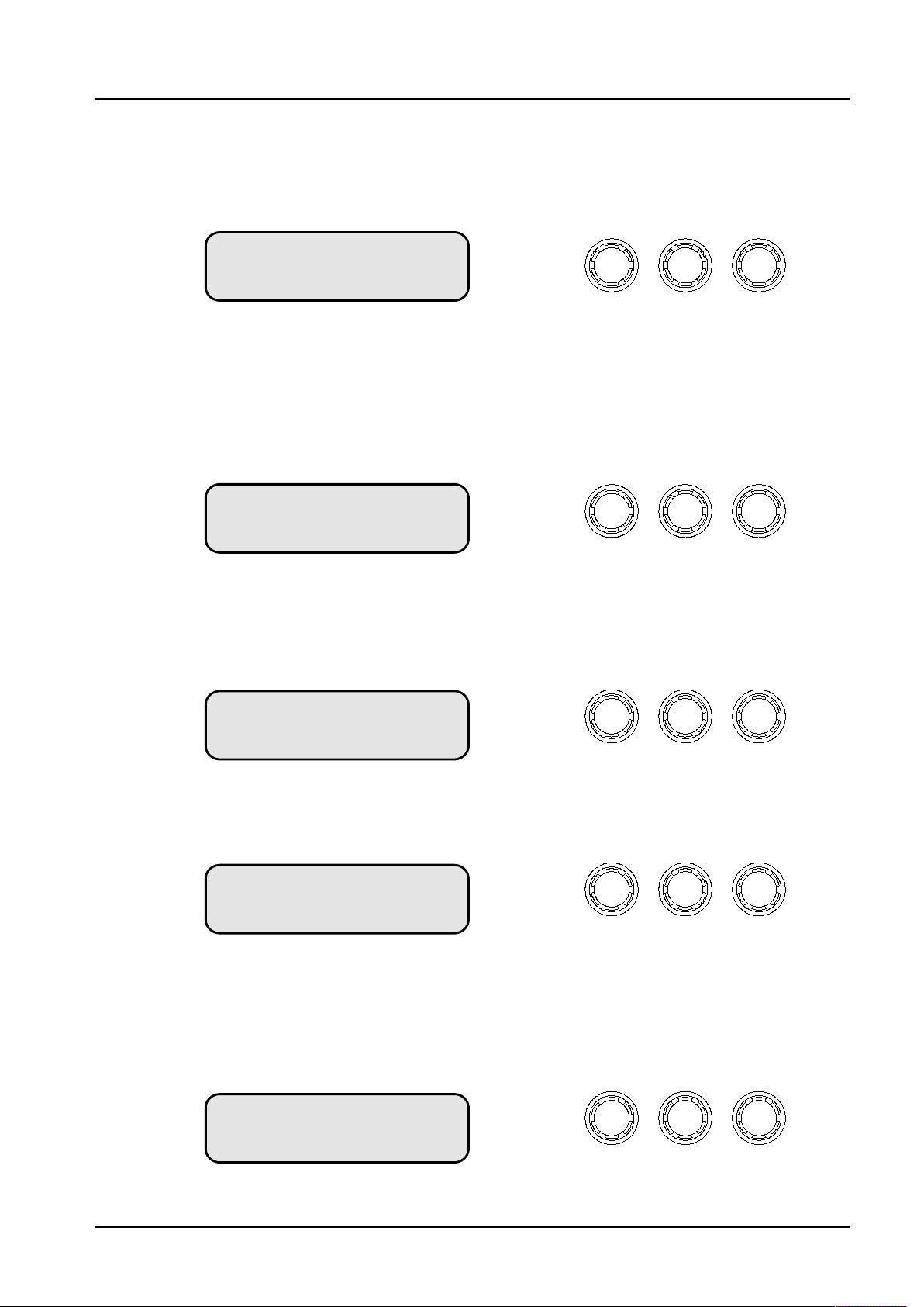
Output Limiter
The limiter on each output has adjustable attack time, release time an d t hreshold.
The range of attack time 0.3 to 90 mS, the range of release time 0.1 to 2.0 seco nd, the range of threshold -10dB to
+15dB in 0.1dB steps.
Out1 Output1 Limiter
A:1 4mS R:2 0S +15dB. .
Attack Release Threshold
Output Channel Name
For edit channel name by pressing ENTER. Cursor will blink on first c haracter po sition .
Turn rotary encoder and modify character, move cursor position by p res sin g BACK or NEXT.
Pressing ENTER again for confirm and store channel name.
Out1 Output1 Name
Name = Output1
Char
Source
The source on each output, can assign signal rounting from input channel, create free Xover combination.
Out1 Output1 Source
Source = A
Pressing ENTER will switch eac h input channel mix gain.
Out1 Output1 InputA
Mix Gain = +0 0dB.
Output Link
Set link value for channel, while modify parameters, the channel of have same link value will mo dify togeth er.
Source
MixGain
Out1 Output1 Link
Link = None
Link
Page 11
Menu System
Pressing MENU will enter menu system. Pr ess ing ENTER w ill enter sub-menu.
MAIN MENU
Program Sub M enu
:.. .. ..
-
MAIN MENU
Interf ace Su b Menu
Program Sub-menu
Load Factory Pro gra m.
Load User Progra m.
Design a Xover.
Save User Pro gra m.
Delete User Program.
PROGRAM MENU
Load User Program
Load User Program
01 2x3 Way Xover:
:...
MAIN MENU
CopyTool s Sub M enu
:.. .. ..
-
Pressing ENTER will enter Load User Program sub-menu.
Turn rotary encoder to ch ange progra m index,
Pressing ENTER
:.. .. ..
-
MAIN MENU
Security Sub Me nu
:.. .. ..
-
MAIN MENU
System Su b Menu
:.. .. ..
-
[ ] .
ENTER for Recall
:
01 2x3 Way Xover
Loading New Program
01 2x3 Way Xover:
PROGRAM MENU
:...
Design a Xover
Design a Xover
Type 2x2 WAY XOVER:
New Xover
ENTER to Confirm[ ]
About Xover mode details, see Appendix I.
Pressing ENTER for confirm and load pr ogr am.
Pressing ENTER will enter Design a Xov er sub-menu .
Turn rotary encoder to ch ange Xov er mode,
Pressing ENTER
Pressing ENTER for confirm and change Xover mode.
Page 12
PROGRAM MENU
Save User Program
:...
Pressing ENTER will enter Save User Program sub-menu.
Save User Program
01 2x3 Way Xover: ?
[ ]
ENTER to Overwrite
: ?
01 2x3 Way Xover
Set Program Name
01 2x3 Way Xover: ?
[ ]
ENTER to Save
: ?
01 2x3 Way Xover
Saving to Memory
01 2x3 Way Xover: ?
Turn rotary encoder to ch ange progra m index,
Pressing ENTER.
Pressing ENTER for confirm and overwrite program.
Pressing QUIT for e xit.
Program name len gth is 1 6 c haracter.
Turn rotary encoder and modify character, move cursor position
by pressing BACK or NEXT.
Pressing ENTER again for confirm and store program name.
Pressing QUIT for e xit.
Pressing ENTER for confirm and Save pr ogram.
PROGRAM MENU
Delete User Program
Delete User Program
01 2x3 Way Xover:
[ ] .
ENTER to Delete
:
01 2x3 Way Xover
Deleting Memory
01 2x3 Way Xover
:
:...
Pressing ENTER will enter Delete User Program sub-men u.
Turn rotary encoder to ch ange progra m index,
Pressing ENTER.
Pressing ENTER for confirm and delete program.
...
Page 13
CopyTools Sub-menu
Copy Input Section
Copy Output Section
COPYTOOLS MENU
:...
Copy Input Section
On Copy Input Section screen, Turn r ota ry “FREQ ”en coder change s ource ch ann el,
Turn rotary “Q” encoder change target channel.
Pressing ENTER to confirm and copy int put channel parameters.
COPYTOOLS MENU
:...
Copy Output Section
On Copy Output Sec tion scr een , Turn rotary “FREQ”encoder change source channel,
Turn rotary “Q” encoder changetarget channel.
Pressing ENTER to confirm and copy out put channel parameters.
Copy Input Section
Source A Target B: :
Copy Output Section
Source 1 Target 2: :
System Sub-menu
SYSTEM MENU
LCD Contrast
:......
Turn rotary encoder to ch ange LCD contrast,
Pressing ENTER to confirm and save.
SYSTEM MENU
LED Brightness
SYSTEM MENU
Wake up Time
-
SYSTEM MENU
Filter Q or BW
:......
:......
:......
Turn rotary encoder to ch ange LED brightness,
Pressing ENTER to confirm and save.
Device startup wake up time.
Mute Hold, set to keep mutes on when powered up.
0 secs......60 secs, set wait time before the audio fades in.
Turn rotary encoder to ch ange parame ter,
Pressing ENTER to confirm and save.
Select filter Q or Bandwidth display uni t.
Turn rotary encoder to ch ange parame ter,
Pressing ENTER to confirm and save.
Page 14
SYSTEM MENU
DelayTime Distance
:......
/
Select delay t ime or d ist ance.
Turn rotary encoder to ch ange parame ter,
Pressing ENTER to confirm and save.
SYSTEM MENU
:......
Output LED Meter
SYSTEM MENU
:......
Load Program Option
SYSTEM MENU
:......
Device Name Title
[ ]
ENTER to Editing
:
Tit Speaker Processor
Select output meter indicate style.
output Level o r attenute on limiter.
Turn rotary encoder to ch ange parame ter,
Pressing ENTER to confirm and save.
Select load program option.
AutoMute: Forc e all output mute on af ter loading program.
LoadMute: Load output MUTE status in program stored.
Turn rotary encoder to ch ange parame ter,
Pressing ENTER to confirm and save.
Change device title name on LCD screen top line.
Pressing ENTER to edit.
Device name length is 16 character.
Turn encoder and modify character.
move cursor position by p res sing BACK or NEXT.
Set Device NameTitle
Tit Speaker Processor:
[ ]
ENTER to Store
:
Tit Speaker Processor
Pressing ENTER for confirm.
Pressing QUIT for e xit.
Pressing ENTER again for confirm and store.
Page 15
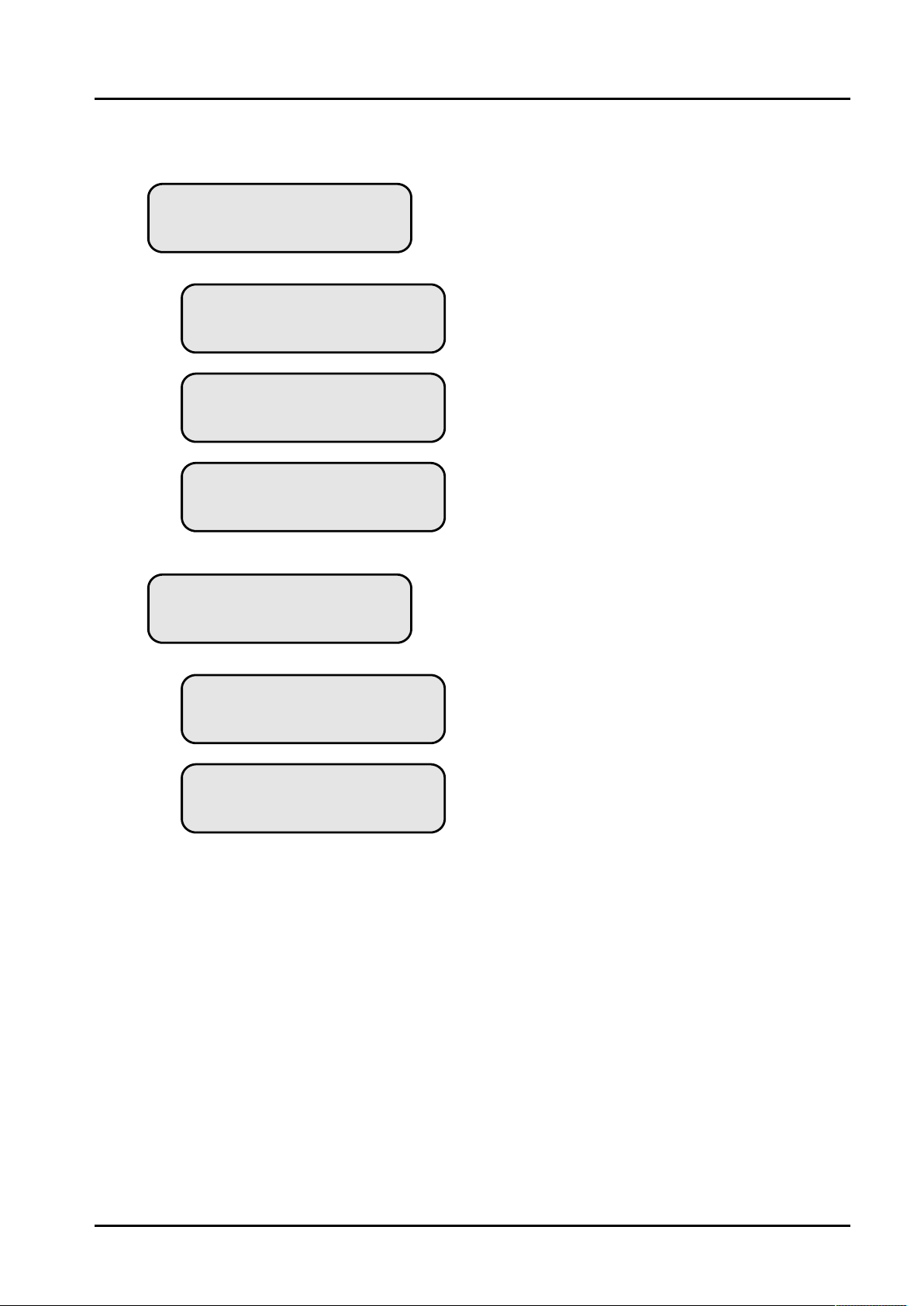
Interface Sub-menu
INTERFACE MENU
Interface Setup
Interface Setup
Master Source: RS232
Interface Setup
Master Source: RS485
Interface Setup
Remote ID Num: 1
INTERFACE MENU
Protocol Setup
:....
Select communicat ion port: RS232 or RS485.
While select RS485.
Need assign a remote ID nu mbe r(1-32).
:....
Protocol Setup
Select: PCsw Ctrl
Protocol Setup
Select: ESRP Ctrl
Select control protocol.
PCsw: select PC co ntr ol.
ESRP: select external s imp le control device.
Page 16
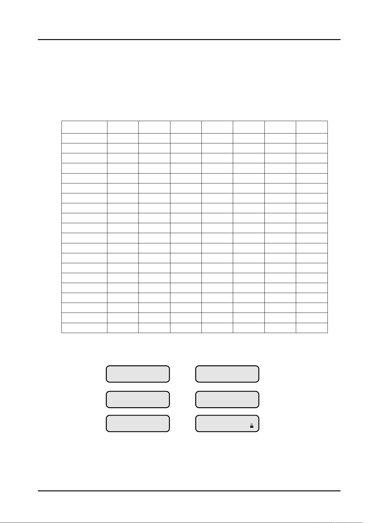
Security Sub-menu
Pressing ENTER will enter Security sub-menu.
Lock status setting:
No Lock: without lock out.
Control: cannot change.
Display: cannot view.
Input Gain
Input Delay
Input PEQs
In GraphEQ
Input Links
Output Gain
Output Delay
Output PEQs
HPFs & LPFs
Output Links
Output Phase
Limiters
Matrix Gains
Input Mutes
Output Mutes
Output Name
Menu System
Memory Store
Memory Load
File Operation
Xover Only
No Lock
No Lock
No Lock
No Lock
No Lock
No Lock
Display
Display
Display
Display
Display
Display
Display
No Lock
No Lock
Control
No Lock
No Lock
No Lock
No Lock
Xover + Trim
No Lock
No Lock
No Lock
No Lock
No Lock
Display
Display
Display
Display
Display
Display
Display
Display
No Lock
No Lock
Control
No Lock
No Lock
No Lock
No Lock
Xover + Trim
+ Mute
No Lock
No Lock
No Lock
No Lock
No Lock
Display
Display
Display
Display
Display
Display
Display
Display
No Lock
Control
Control
No Lock
No Lock
No Lock
No Lock
Cha nges O nly Ch anges + Mut esCha nges + View
Control
Control
Control
Control
Control
Control
Control
Control
Control
Control
Control
Control
Control
No Lock
No Lock
Control
No Lock
No Lock
No Lock
No Lock
Display
Display
Display
Display
Display
Display
Display
Display
Display
Display
Display
Display
Display
No Lock
No Lock
Control
No Lock
No Lock
No Lock
No Lock
Control
Control
Control
Control
Control
Control
Control
Control
Control
Control
Control
Control
Control
Control
Control
Control
No Lock
No Lock
No Lock
No Lock
EVE RYTHING
Display
Display
Display
Display
Display
Display
Display
Display
Display
Display
Display
Display
Display
Control
Control
Control
Control
Control
Control
Control
In “User Specific” setting, you can free set up lock status depend on each function part.
Enter Passwo rd
[** ** ** ]
Confirm Passw ord
[** ** ** ]
Locking U nit
[** ** ** ]
Enter Passwo rd
[** ** ** ]
UnLock ing Un it
[** ** ** ]
Speake r Pro cessor
2 X 3 Way Xo ver
Pressing ENTER will enter password.
Turn rotary encoder and modify character, move cursor position by p res sin g BACK or NEXT.
Pressing ENTER for enter passw ord again.
while twice time password match, system will lock unit.
Page 17

Specifications
Inputs: 2/3/4 electronically balanced.
Impedance: > 10k ohms.
CMRR: > 75dB 50 Hz ~ 10kHz.
Outputs: 4/6/8 electronicall y b alanced.
Source Imp: < 60ohms
Min. Load: 600ohm
Max. Level: +15dBm
Digital Audio Sample Rate: 96kHz
Frequency Response: +/- 0.5dB, 20Hz ~ 2 0kH z
Distortion: < 0.006% @1kHz, +15dBm
ADC Dynamic Range: > 110dB, 20Hz ~ 20kHz (A-Weig ht)
DAC Dynamic Range: > 110dB, 20Hz ~ 20kHz (A-Weight)
Propagation Delay: 0.41mS (DP240 / DP260 / DP440)
0.34mS (DP280AL / DP360)
Delay: 1000mS(Inp ut) , 1000mS(Ou tpu t)
Min Step Size: 0.010mS(4mm)
Input Gain: -40dB to + 6dB in 0.1d B s teps
Output Gain: -40d B to +15dB in 0.1dB steps
Multi-Type F ilters
10 per Input, 7 per Out put .
Freq. Range: 20Hz ~ 20kHz, 1/36 Octave steps.
Filter Q/BW: 0.4 to 128.
Filter Type: Parametric Equaliser
HiShelf, LoShelf
Variable Q Highpass, Lowpass
Bandpass, Notch, Allpass.
High and Lowpass Filters
Freq. Range: 20Hz ~ 20kHz, 1/36 Octave steps.
Slope: 6/12/18/24 /36 /48 dB/Octa ve.
Type: Butterworth, Linkwitz-Riley, Bessel.
Limiters
Threshold: -10 ~ +15dB, 1dB steps.
Attack time: 0.3 ~ 90mS.
Release time: 0. 1 ~ 2.0 second.
Display: 2x20 Character LCD
Connectors
Inputs: 3 pin female XLR
Output: 3 pin male XLR
RS232: 9 pin DEE connector
RS485: RJ45 style connector
Power: 3 pin IEC
Power Voltage: ~220V @50/60Hz
Power Consumption: < 17 watts
Weight: 2.7kg. Net (4.0kg. Shipping)
Size: 1.75”(1U) x 19” x 8. 0” (44 x 482 x 205 mm)
Page 18
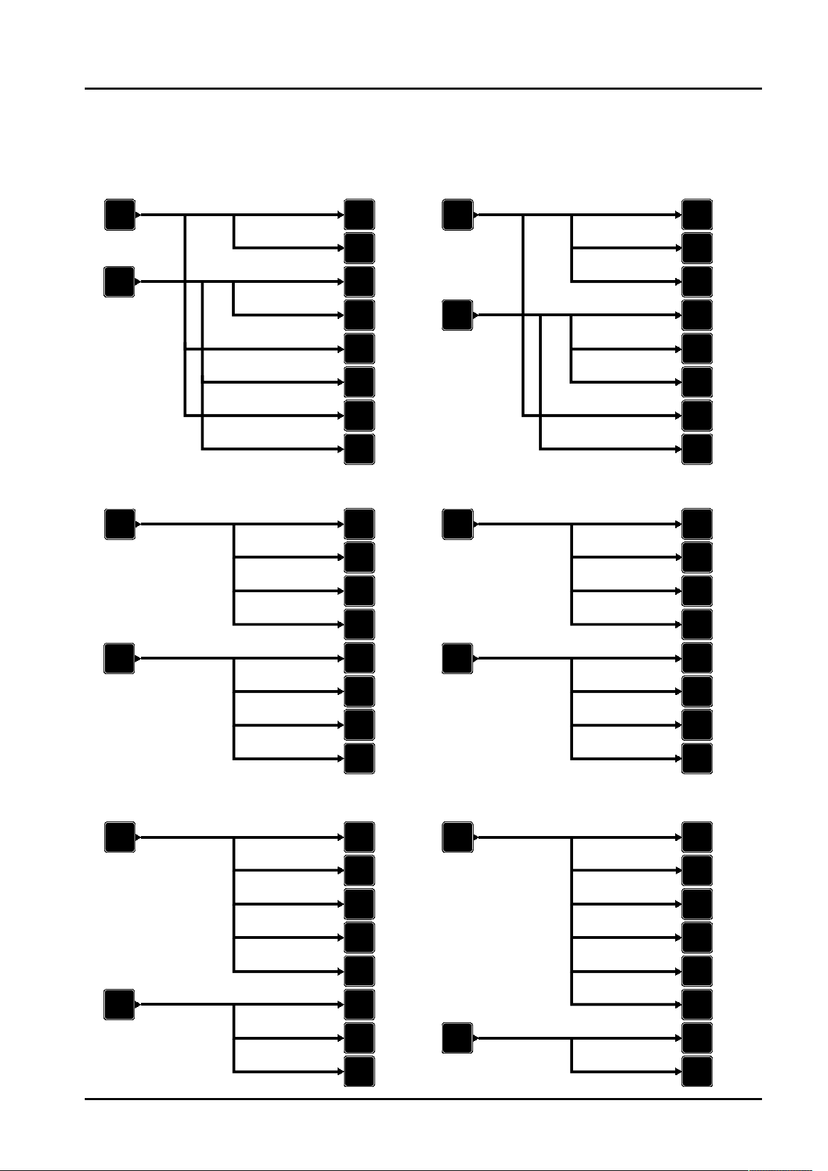
Appendix I - Crossover Configurations
2x2 Way DP280( ) 2x3 Way DP280( )
INP UT
A
OUT PUT
1
OUT PUT
INP UT
A
2
INP UT
B
OUT PUT
3
OUT PUT
4
OUT PUT
INP UT
B
5
OUT PUT
6
OUT PUT
7
OUT PUT
8
2x4 Way DP280( ) 4+4 Way DP280( )
INP UT
A
INP UT
B
OUT PUT
1
OUT PUT
2
OUT PUT
3
OUT PUT
4
OUT PUT
5
OUT PUT
6
OUT PUT
7
OUT PUT
8
INP UT
A
INP UT
B
OUT PUT
1
OUT PUT
2
OUT PUT
3
OUT PUT
4
OUT PUT
5
OUT PUT
6
OUT PUT
7
OUT PUT
8
OUT PUT
1
OUT PUT
2
OUT PUT
3
OUT PUT
4
OUT PUT
5
OUT PUT
6
OUT PUT
7
OUT PUT
8
5+3 Way DP280( )
INP UT
A
INP UT
B
OUT PUT
1
OUT PUT
2
OUT PUT
3
OUT PUT
4
OUT PUT
5
OUT PUT
6
OUT PUT
7
OUT PUT
8
6+2 Way DP280( )
INP UT
A
INP UT
B
OUT PUT
1
OUT PUT
2
OUT PUT
3
OUT PUT
4
OUT PUT
5
OUT PUT
6
OUT PUT
7
OUT PUT
8
Page 19
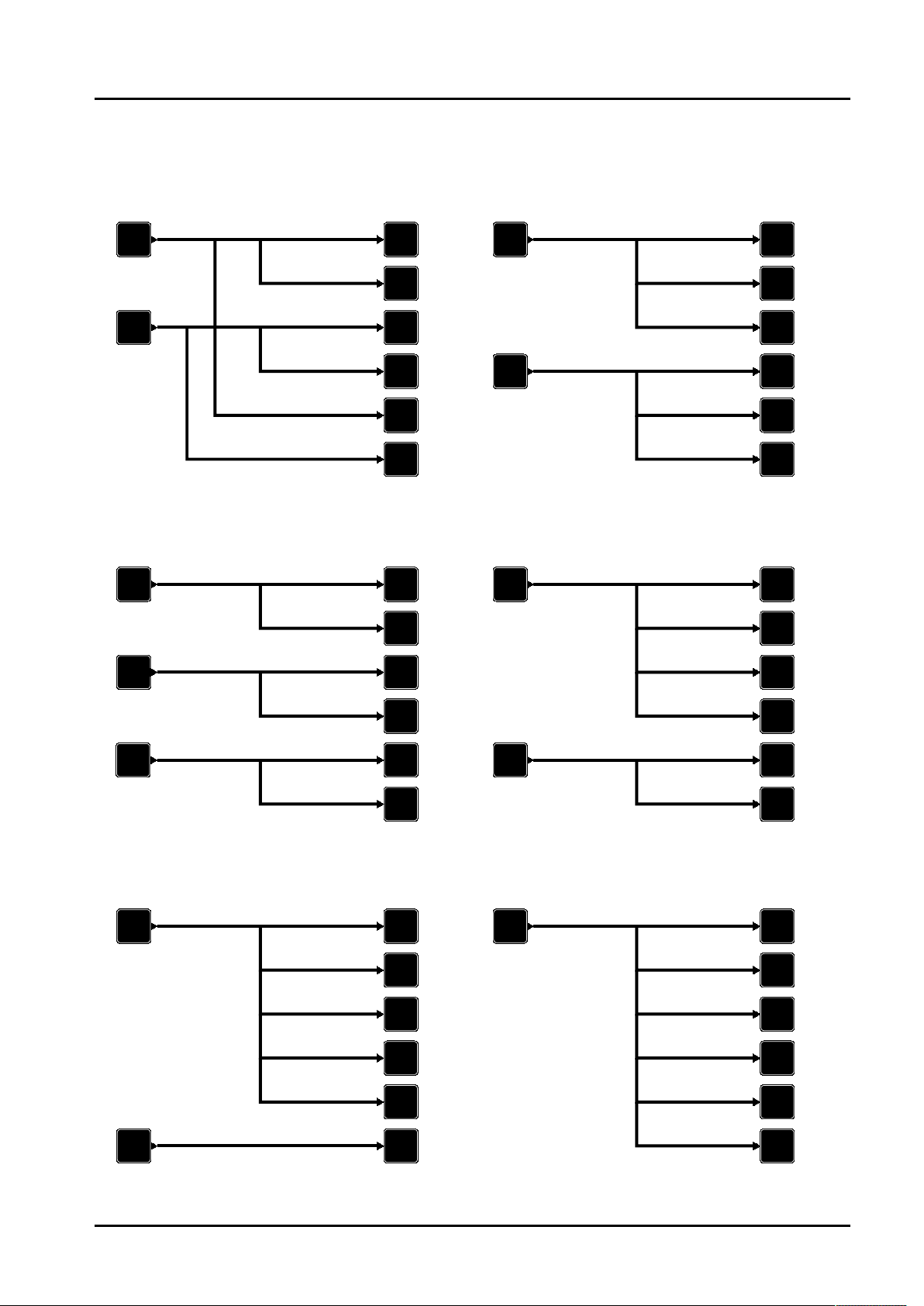
2x2 Way /DP260( )DP360 2x3 Way /DP260( )DP360
INP UT
A
INP UT
B
3x2 Way DP360( )
INP UT
A
INP UT
B
OUT PUT
1
OUT PUT
2
OUT PUT
3
OUT PUT
4
OUT PUT
5
OUT PUT
6
OUT PUT
1
OUT PUT
2
OUT PUT
3
INP UT
A
INP UT
B
4+2 Way /DP260( )DP360
INP UT
A
OUT PUT
1
OUT PUT
2
OUT PUT
3
OUT PUT
4
OUT PUT
5
OUT PUT
6
OUT PUT
1
OUT PUT
2
OUT PUT
3
OUT PUT
4
INP UT
C
OUT PUT
5
OUT PUT
INP UT
B
6
5+1 Way /DP260( )DP360 6 Way /DP260( )DP360
INP UT
A
INP UT
B
OUT PUT
1
OUT PUT
2
OUT PUT
3
OUT PUT
4
OUT PUT
5
OUT PUT
6
INP UT
A
OUT PUT
4
OUT PUT
5
OUT PUT
6
OUT PUT
1
OUT PUT
2
OUT PUT
3
OUT PUT
4
OUT PUT
5
OUT PUT
6
Page 20
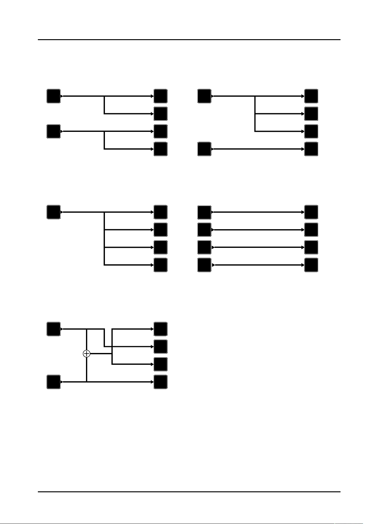
2x2 Way DP440/DP240( ) 3+1 Way DP440/DP240( )
INP UT
A
OUT PUT
1
OUT PUT
INP UT
A
2
INP UT
B
OUT PUT
3
OUT PUT
4
INP UT
B
4 Way DP440/DP240( ) 4x1 Way DP440( )
INP UT
A
OUT PUT
1
OUT PUT
2
OUT PUT
3
OUT PUT
4
INP UT
A
INP UT
B
INP UT
C
INP UT
D
OUT PUT
1
OUT PUT
2
OUT PUT
3
OUT PUT
4
OUT PUT
1
OUT PUT
2
OUT PUT
3
OUT PUT
4
2 Mono Sub DP240( )
INP UT
A
INP UT
B
OUT PUT
1
OUT PUT
2
OUT PUT
3
OUT PUT
4
Page 21
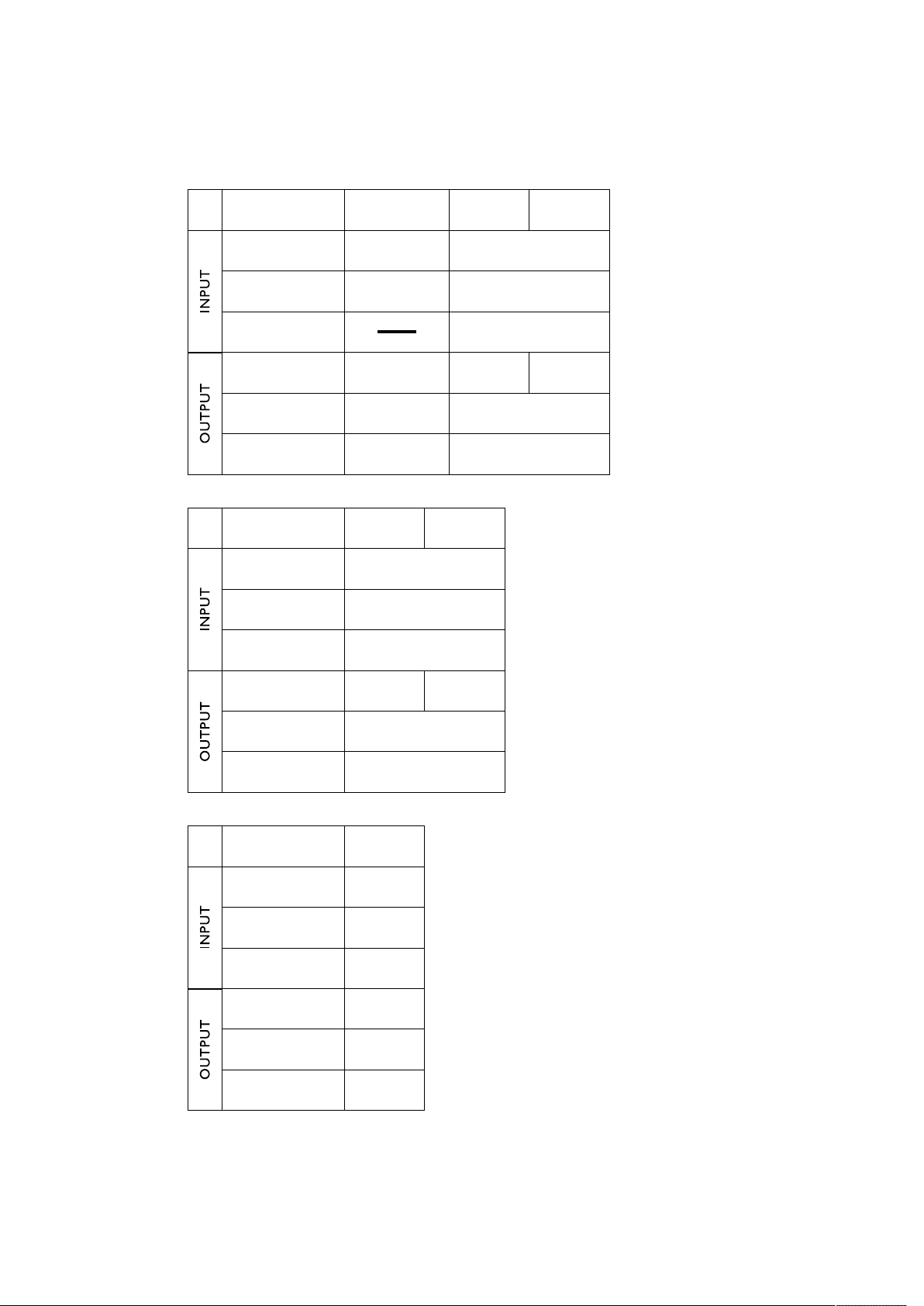
Appendix II - Different Device Comparision
Model
Channel
Delay
Filter
Channel
Filter
Delay
Model
Channel
Delay
Filter
DP280AL
2 2
1000mS
8 6
7
1000mS 1000mS
DP340DP360
3
1000mS
7
1000mS
10
7
DP240DP260
4
Channel
Filter
Delay
Model
Channel
Delay
Filter
Channel
Filter
Delay
6
DP440
4
1000mS
10
4
7
1000mS
4
7
1000mS
 Loading...