

Page 1
CMR Electrical Ltd
BoltonHouse
Five Chimneys Lane
Hadlow Down
East Sussex
TN22 4DX
Tel: 01825 733600
RWM
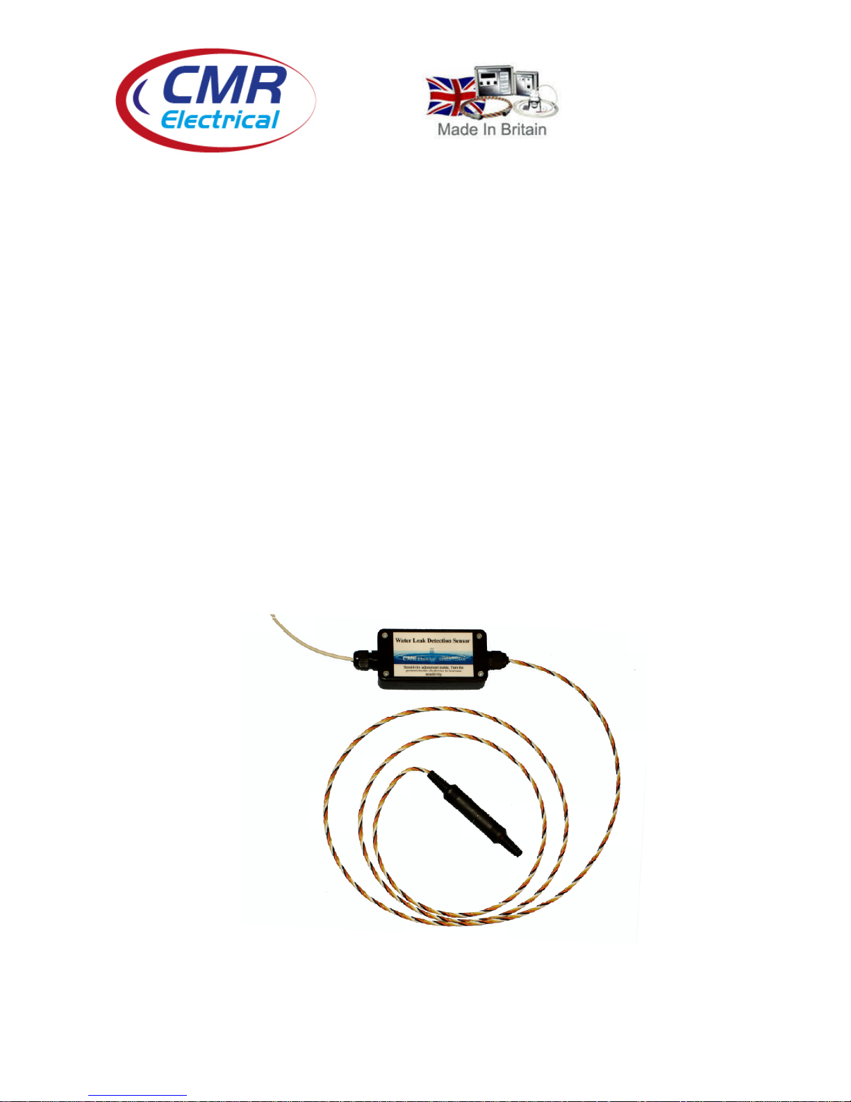
Water Leak Detection Sensor
Installation and Operation
Manual
Page 2
2
Installation
The detection sensor is susceptible to damage and should not be fitted to areas where it is likely to be
damaged or walked on.
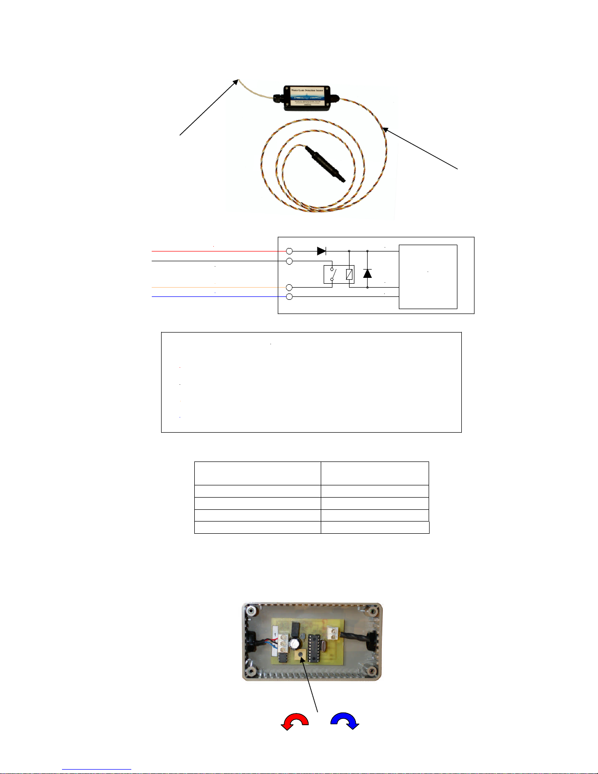
Sensor wiring
Sensor
Red
Green
Blue
Red
Black
Yellow
Blue
RedWire=12-24VACliveor13-24VDC+
BlueWire = 12- 24VACNeutralor13- 24VDCnegative
BlackWire=Volt freeContactcommon
YellowWire =Volt FreeContactNormallyOpen,Closeinalarm
Connections
The signal cable should be terminated between the sensor and the main Alarm/BMS in the following
manner.
Main Controller terminal
number
Signal wire colour
+VDC/AC Red
0VDC/AC Blue
Contact N/O Yellow
Contact N/O Black
Sensitivity adjustment
To increase the sensitivity of the cable turn the potentiometer CLOCKWISE, to de-crease the sensitivity
turn ANTICLOCKWISE.
Signal Cable
Detection Cable
Signal Cable
Detection Cable
Increase Sensitivity
Decrease Sensitivity
 Loading...